EP2584230A1 - Valve, hydraulic assembly with such a valve and use of a button or switch for a valve - Google Patents

Valve, hydraulic assembly with such a valve and use of a button or switch for a valve Download PDF

Info

Publication number
EP2584230A1
EP2584230A1 EP12185588.6A EP12185588A EP2584230A1 EP 2584230 A1 EP2584230 A1 EP 2584230A1 EP 12185588 A EP12185588 A EP 12185588A EP 2584230 A1 EP2584230 A1 EP 2584230A1
Authority
EP
European Patent Office
Prior art keywords
valve
spring
sensor
pressure
spool
Prior art date
Legal status (The legal status is an assumption and is not a legal conclusion. Google has not performed a legal analysis and makes no representation as to the accuracy of the status listed.)
Granted
Application number
EP12185588.6A
Other languages
German (de)
French (fr)
Other versions
EP2584230B1 (en
Inventor
Davide Pingani
Andrea Tamelli
Current Assignee (The listed assignees may be inaccurate. Google has not performed a legal analysis and makes no representation or warranty as to the accuracy of the list.)
Robert Bosch GmbH
Original Assignee
Robert Bosch GmbH
Priority date (The priority date is an assumption and is not a legal conclusion. Google has not performed a legal analysis and makes no representation as to the accuracy of the date listed.)
Filing date
Publication date
Application filed by Robert Bosch GmbH filed Critical Robert Bosch GmbH
Publication of EP2584230A1 publication Critical patent/EP2584230A1/en
Application granted granted Critical
Publication of EP2584230B1 publication Critical patent/EP2584230B1/en
Not-in-force legal-status Critical Current
Anticipated expiration legal-status Critical

Links

Images

Classifications

    • FMECHANICAL ENGINEERING; LIGHTING; HEATING; WEAPONS; BLASTING
    • F15FLUID-PRESSURE ACTUATORS; HYDRAULICS OR PNEUMATICS IN GENERAL
    • F15BSYSTEMS ACTING BY MEANS OF FLUIDS IN GENERAL; FLUID-PRESSURE ACTUATORS, e.g. SERVOMOTORS; DETAILS OF FLUID-PRESSURE SYSTEMS, NOT OTHERWISE PROVIDED FOR
    • F15B13/00Details of servomotor systems ; Valves for servomotor systems
    • F15B13/02Fluid distribution or supply devices characterised by their adaptation to the control of servomotors
    • F15B13/04Fluid distribution or supply devices characterised by their adaptation to the control of servomotors for use with a single servomotor
    • F15B13/0401Valve members; Fluid interconnections therefor
    • F15B13/0402Valve members; Fluid interconnections therefor for linearly sliding valves, e.g. spool valves
    • FMECHANICAL ENGINEERING; LIGHTING; HEATING; WEAPONS; BLASTING
    • F15FLUID-PRESSURE ACTUATORS; HYDRAULICS OR PNEUMATICS IN GENERAL
    • F15BSYSTEMS ACTING BY MEANS OF FLUIDS IN GENERAL; FLUID-PRESSURE ACTUATORS, e.g. SERVOMOTORS; DETAILS OF FLUID-PRESSURE SYSTEMS, NOT OTHERWISE PROVIDED FOR
    • F15B2211/00Circuits for servomotor systems
    • F15B2211/30Directional control
    • F15B2211/305Directional control characterised by the type of valves
    • F15B2211/30505Non-return valves, i.e. check valves
    • F15B2211/30515Load holding valves
    • FMECHANICAL ENGINEERING; LIGHTING; HEATING; WEAPONS; BLASTING
    • F15FLUID-PRESSURE ACTUATORS; HYDRAULICS OR PNEUMATICS IN GENERAL
    • F15BSYSTEMS ACTING BY MEANS OF FLUIDS IN GENERAL; FLUID-PRESSURE ACTUATORS, e.g. SERVOMOTORS; DETAILS OF FLUID-PRESSURE SYSTEMS, NOT OTHERWISE PROVIDED FOR
    • F15B2211/00Circuits for servomotor systems
    • F15B2211/40Flow control
    • F15B2211/405Flow control characterised by the type of flow control means or valve
    • F15B2211/40523Flow control characterised by the type of flow control means or valve with flow dividers
    • F15B2211/4053Flow control characterised by the type of flow control means or valve with flow dividers using valves
    • FMECHANICAL ENGINEERING; LIGHTING; HEATING; WEAPONS; BLASTING
    • F15FLUID-PRESSURE ACTUATORS; HYDRAULICS OR PNEUMATICS IN GENERAL
    • F15BSYSTEMS ACTING BY MEANS OF FLUIDS IN GENERAL; FLUID-PRESSURE ACTUATORS, e.g. SERVOMOTORS; DETAILS OF FLUID-PRESSURE SYSTEMS, NOT OTHERWISE PROVIDED FOR
    • F15B2211/00Circuits for servomotor systems
    • F15B2211/40Flow control
    • F15B2211/41Flow control characterised by the positions of the valve element
    • F15B2211/413Flow control characterised by the positions of the valve element the positions being continuously variable, e.g. as realised by proportional valves
    • FMECHANICAL ENGINEERING; LIGHTING; HEATING; WEAPONS; BLASTING
    • F15FLUID-PRESSURE ACTUATORS; HYDRAULICS OR PNEUMATICS IN GENERAL
    • F15BSYSTEMS ACTING BY MEANS OF FLUIDS IN GENERAL; FLUID-PRESSURE ACTUATORS, e.g. SERVOMOTORS; DETAILS OF FLUID-PRESSURE SYSTEMS, NOT OTHERWISE PROVIDED FOR
    • F15B2211/00Circuits for servomotor systems
    • F15B2211/40Flow control
    • F15B2211/415Flow control characterised by the connections of the flow control means in the circuit
    • F15B2211/41572Flow control characterised by the connections of the flow control means in the circuit being connected to a pressure source and an output member
    • FMECHANICAL ENGINEERING; LIGHTING; HEATING; WEAPONS; BLASTING
    • F15FLUID-PRESSURE ACTUATORS; HYDRAULICS OR PNEUMATICS IN GENERAL
    • F15BSYSTEMS ACTING BY MEANS OF FLUIDS IN GENERAL; FLUID-PRESSURE ACTUATORS, e.g. SERVOMOTORS; DETAILS OF FLUID-PRESSURE SYSTEMS, NOT OTHERWISE PROVIDED FOR
    • F15B2211/00Circuits for servomotor systems
    • F15B2211/40Flow control
    • F15B2211/42Flow control characterised by the type of actuation
    • F15B2211/426Flow control characterised by the type of actuation electrically or electronically
    • FMECHANICAL ENGINEERING; LIGHTING; HEATING; WEAPONS; BLASTING
    • F15FLUID-PRESSURE ACTUATORS; HYDRAULICS OR PNEUMATICS IN GENERAL
    • F15BSYSTEMS ACTING BY MEANS OF FLUIDS IN GENERAL; FLUID-PRESSURE ACTUATORS, e.g. SERVOMOTORS; DETAILS OF FLUID-PRESSURE SYSTEMS, NOT OTHERWISE PROVIDED FOR
    • F15B2211/00Circuits for servomotor systems
    • F15B2211/50Pressure control
    • F15B2211/505Pressure control characterised by the type of pressure control means
    • F15B2211/50563Pressure control characterised by the type of pressure control means the pressure control means controlling a differential pressure
    • F15B2211/50581Pressure control characterised by the type of pressure control means the pressure control means controlling a differential pressure using counterbalance valves
    • F15B2211/5059Pressure control characterised by the type of pressure control means the pressure control means controlling a differential pressure using counterbalance valves using double counterbalance valves
    • FMECHANICAL ENGINEERING; LIGHTING; HEATING; WEAPONS; BLASTING
    • F15FLUID-PRESSURE ACTUATORS; HYDRAULICS OR PNEUMATICS IN GENERAL
    • F15BSYSTEMS ACTING BY MEANS OF FLUIDS IN GENERAL; FLUID-PRESSURE ACTUATORS, e.g. SERVOMOTORS; DETAILS OF FLUID-PRESSURE SYSTEMS, NOT OTHERWISE PROVIDED FOR
    • F15B2211/00Circuits for servomotor systems
    • F15B2211/60Circuit components or control therefor
    • F15B2211/63Electronic controllers
    • F15B2211/6303Electronic controllers using input signals
    • F15B2211/634Electronic controllers using input signals representing a state of a valve
    • FMECHANICAL ENGINEERING; LIGHTING; HEATING; WEAPONS; BLASTING
    • F15FLUID-PRESSURE ACTUATORS; HYDRAULICS OR PNEUMATICS IN GENERAL
    • F15BSYSTEMS ACTING BY MEANS OF FLUIDS IN GENERAL; FLUID-PRESSURE ACTUATORS, e.g. SERVOMOTORS; DETAILS OF FLUID-PRESSURE SYSTEMS, NOT OTHERWISE PROVIDED FOR
    • F15B2211/00Circuits for servomotor systems
    • F15B2211/70Output members, e.g. hydraulic motors or cylinders or control therefor
    • F15B2211/705Output members, e.g. hydraulic motors or cylinders or control therefor characterised by the type of output members or actuators
    • F15B2211/7058Rotary output members

Abstract

The valve has a valve body which is movable in two switching positions. A sensor (44) is provided which is activated in one of the switching position of the valve body and is deactivated in another switching position. The sensor is designed as a push button or a switch. A detection piston is provided, over which the sensor activated through the valve body. The detection piston is clamped in its end position by a spring force of a spring. An independent claim is included for a hydraulic arrangement with a locking valve.

Description

Die Erfindung geht aus von einem Ventil, das eine Positionserkennung aufweist, von einer hydraulischen Anordnung mit einem derartigen Ventil und von einer Verwendung eines Tasters oder Schalters für ein Ventil.The invention is based on a valve which has a position detection, a hydraulic arrangement with such a valve and a use of a button or switch for a valve.

In der DE 10 2006 049 724 A1 ist ein Ventil mit einer Positionserkennung eines Ventilelements vorgesehen. Das Ventil hat ein Ventilgehäuse in dem das Ventilelement verschiebbar geführt ist. An dem Ventilelement ist ein Permanentmagnet angeordnet, der mit einem Magnetfeldsensor zur Positionserkennung des Ventilelements zusammenwirkt. Nachteilig bei dieser Lösung ist, dass eine derartige Positionserfassung vorrichtungstechnisch äußerst aufwendig ist.In the DE 10 2006 049 724 A1 a valve is provided with a position detection of a valve element. The valve has a valve housing in which the valve element is slidably guided. On the valve element, a permanent magnet is arranged, which cooperates with a magnetic field sensor for detecting the position of the valve element. A disadvantage of this solution is that such a position detection device technology is extremely expensive.

Aus dem Stand der Technik sind des Weiteren Schieberventile bekannt, bei denen eine Vorrichtung zur Positionserkennung direkt auf einem Ventilschieber angeordnet ist, oder mit einem Schaltmagneten des Ventilschiebers zusammenwirkt. Eine direkte Montage auf einem Ventilschieber erfordert Sensoren mit einer äußerst hohen Messgenauigkeit aufgrund der geringe Toleranzen aufweisenden Neutralstellung des Ventilschiebers. Die Vorrichtung zur Positionserkennung muss hierbei aufwendig kalibriert werden, was zu hohen Kosten führt.Furthermore, slide valves are known from the prior art, in which a device for position detection is arranged directly on a valve slide, or cooperates with a switching magnet of the valve slide. Direct mounting on a valve spool requires sensors with a very high accuracy due to the low tolerances neutral position of the valve spool. The device for position detection must be calibrated consuming, which leads to high costs.

Demgegenüber liegt der Erfindung die Aufgabe zugrunde, ein Ventil und eine hydraulische Anordnung mit einem derartigen Ventil zu schaffen, bei denen die Position eines Ventilkörpers des Ventils vorrichtungstechnisch einfach und kostengünstig erfassbar ist. Diese Aufgabe wird hinsichtlich des Ventils mit den Merkmalen des Patentanspruchs 1 und hinsichtlich der hydraulischen Anordnung mit den Merkmalen des Patentanspruchs 12 gelöst.In contrast, the invention has for its object to provide a valve and a hydraulic arrangement with such a valve, in which the position of a valve body of the valve device is simple and inexpensive detectable. This object is achieved with regard to the valve having the features of patent claim 1 and with regard to the hydraulic arrangement having the features of patent claim 12.

Erfindungsgemäß hat ein Ventil, insbesondere ein Schieberventil oder ein Sitzventil, beispielsweise ein Kegel-, Kugel- oder Teller-Sitzventil, einen Ventilkörper, der in zumindest zwei Schaltpositionen verschiebbar ist. Hierbei ist ein Sensor vorgesehen, der bei einer Anordnung des Ventilkörpers in einer der Schaltstellungen aktiviert und bei der Anordnung des Ventilkörpers in der anderen Schaltstellung deaktiviert ist.According to the invention, a valve, in particular a slide valve or a seat valve, for example a conical, ball or seat valve seat, a valve body which is displaceable in at least two switching positions. In this case, a sensor is provided which is activated in an arrangement of the valve body in one of the switching positions and deactivated in the arrangement of the valve body in the other switching position.

Diese Lösung hat den Vorteil, dass zumindest zwei Positionen des Ventilkörpers mit einem vorrichtungstechnisch äußerst einfach aufgebauten Sensor bestimmt werden können.This solution has the advantage that at least two positions of the valve body can be determined with a sensor device of extremely simple construction.

Mit Vorteil ist der Sensor als elektrischer Taster oder elektrischer Schalter ausgebildet. Ein derartiger Sensor kann bei den unterschiedlichsten Ventiltypen eingesetzt werden und muss im Unterschied zum Stand der Technik nicht individuell für ein jeweiliges Ventil kalibriert werden. Dies führt zu einem geringem Herstellungs- und Montageaufwand und ist somit äußerst kostengünstig.Advantageously, the sensor is designed as an electrical button or electrical switch. Such a sensor can be used in a wide variety of valve types and, unlike the prior art, does not have to be individually calibrated for a respective valve. This leads to a low production and assembly costs and is thus extremely cost-effective.

In weiterer Ausgestaltung der Erfindung kann zusätzlich zum Ventilkörper ein Detektionskolben vorgesehen sein, über den der Sensor vom Ventilkörper aktivierbar ist. Der Ventilkörper ist somit nicht direkt in Wirkverbindung mit dem Sensor und kann in herkömmlicher Weise ausgestaltet sein.In a further embodiment of the invention, in addition to the valve body, a detection piston may be provided, via which the sensor can be activated by the valve body. The valve body is thus not directly in operative connection with the sensor and can be configured in a conventional manner.

Bevorzugter Weise ist das Ventil ein Schieberventil und der Ventilkörper ein Ventilschieber. Eine Schaltstellung des Ventilschiebers kann dann die Neutralstellung sein, in der der Ventilschieber beispielsweise federzentriert ist. Der Ventilschieber kann dann von der Neutralstellung aus in Richtung der weiteren Schaltstellungen verschiebbar sein, in denen der Sensor durch den Ventilschieber aktiviert ist.Preferably, the valve is a spool valve and the valve body is a valve spool. A switching position of the valve spool can then be the neutral position, in which the valve spool, for example, is spring-centered. The valve spool can then be displaced from the neutral position in the direction of the further switching positions, in which the sensor is activated by the valve spool.

Es ist denkbar, dass der Ventilschieber von einer Neutralstellung in entgegengesetzte Richtungen in eine jeweilige Schaltstellung verschiebbar ist. Hierbei können zwei Sensoren vorgesehen sein. Einer der Sensoren ist dann bei einer Verschiebung des Ventilschiebers von der Neutralstellung in die eine Richtung aktiviert und der andere Sensor ist bei einer Verschiebung der Ventilschiebers von der Neutralstellung in die andere Richtung aktiviert. Damit ist zum Einen auf einfache Weise die Anordnung des Ventilschiebers in seiner Neutralstellung feststellbar und zum Anderen ist die Verschieberichtung des Ventilschiebers außerhalb seiner Neutralstellung feststellbar.It is conceivable that the valve spool is displaceable from a neutral position in opposite directions in a respective switching position. In this case, two sensors can be provided. One of the sensors is then activated when the valve spool is displaced from the neutral position in one direction and the other sensor is activated when the valve spool is displaced from the neutral position in the other direction. This is on the one hand in a simple way, the arrangement of the valve spool Detectable in its neutral position and on the other hand, the direction of displacement of the valve spool is detected outside its neutral position.

Mit Vorteil ist für jeden Sensor ein Detektionskolben vorgesehen, der sich jeweils vorrichtungstechnisch einfach koaxial zum Ventilschieber erstreckt und in eine Endposition in Richtung des Ventilschiebers verfahrbar ist. Ein jeweiliger Detektionskolben kann dann aus seiner Endposition durch den Ventilschieber herausbewegt werden, wodurch dann der dem jeweiligen Detektionskolben zugeordnete Sensor von dem Detektionskolben aktiviert ist.Advantageously, a detection piston is provided for each sensor, which each device-wise simply coaxial with the valve spool and is movable in an end position in the direction of the valve spool. A respective detection piston can then be moved out of its end position by the valve slide, whereby then the sensor associated with the respective detection piston is activated by the detection piston.

Zum Verschieben eines jeweiligen Detektionskolbens in seine Endposition kann einfach eine Feder eingesetzt werden, die den Detektionskolben in Richtung seiner Endposition mit einer Federkraft beaufschlagt.For moving a respective detection piston into its end position, a spring can be simply used, which acts on the detection piston in the direction of its end position with a spring force.

Vorteilhafterweise wird der Ventilschieber dann über die Feder des jeweiligen Detektionskolbens ebenfalls mit der Federkraft beaufschlagbar, wodurch er in seiner Neutralstellung federzentriert ist. In der Neutralstellung sind dann beide Detektionskolben im Wesentlichen in ihren Endpositionen.Advantageously, the valve spool is then acted upon by the spring of the respective detection piston also with the spring force, whereby it is spring-centered in its neutral position. In the neutral position, then, both detection pistons are essentially in their end positions.

Das Ventil kann einen ersten Druckmittelströmungspfad und einen zweiten unabhängigen Druckmittelströmungspfad steuern. Der Ventilschieber hat dann eine erste und zweite Steuerfläche, die voneinander weg weisen. Bei einer Druckbeaufschlagung einer jeweiligen Steuerfläche ist der Ventilschieber in seine Schaltstellungen verschiebbar. Die erste Steuerfläche ist dabei vom Druck im ersten Druckmittelströmungspfad und die zweite Steuerfläche vom Druck im zweiten Druckmittelströmungspfad beaufschlagbar.The valve may control a first pressure medium flow path and a second independent pressure medium flow path. The valve spool then has first and second control surfaces facing away from each other. When pressurizing a respective control surface of the valve spool is displaced in its switching positions. The first control surface is acted upon by the pressure in the first pressure medium flow path and the second control surface by the pressure in the second pressure medium flow path.

Jede der Steuerflächen des Ventilschiebers kann hierbei einen Druckraum begrenzen, in dem dann auch ein jeweiliger Detektionskolben mündet und mit dem Ventilschieber mechanisch in Wirkverbindung bringbar ist. Eine Druckangriffsfläche eines jeweiligen Detektionskolbens, auf die ein jeweiliger Druck in dem jeweiligen Druckraum in einer Verschieberichtung des Detektionskolbens weg von seiner Endposition und entgegen der Federkraft der Feder wirkt, ist dabei derart gewählt, dass der Detektionskolben nicht entgegen der Federkraft der Feder aufgrund dieses Drucks im Druckraum verschiebbar ist. Hierdurch wird vermieden, dass der durch den jeweiligen Detektionskolben aktivierte Schalter durch einen Druck und nicht durch den Ventilschieber aktiviert wird. Die Druckangriffsfläche eines jeweiligen Detektionskolbens kann dabei kleiner als die jeweilige Steuerfläche des Ventilschiebers sein.Each of the control surfaces of the valve slide can in this case limit a pressure chamber, in which then also a respective detection piston opens and can be mechanically brought into operative connection with the valve slide. A pressure application surface of a respective detection piston, to which a respective pressure in the respective pressure chamber in a direction of displacement of the detection piston acts away from its end position and against the spring force of the spring, is selected such that the detection piston does not counteract the spring force of the spring due to this pressure in Displaceable pressure chamber is. This avoids that the activated by the respective detection piston switch is activated by a pressure and not by the valve spool. The pressure application surface of a respective detection piston may be smaller than the respective control surface of the valve spool.

Der Detektionskolben kann zweiteilig ausgestaltet sein und einen im Wesentlichen kreiszylindrischen Stift zur mechanischen Kontaktierung des Ventilschiebers und einen Federteller, insbesondere einen Abschnitt mit einem Federteller, aufweisen, der zum einen den Sensor aktivieren kann und zum anderen mit der Federkraft der dem Detektionskolben zugeordneten Feder beaufschlagbar ist. Eine Detektionskolben ist dabei des Weiteren über seinen Federteller in seiner Endposition haltbar, insbesondere, indem dieser an einem Sitz anliegt.The detection piston can be designed in two parts and have a substantially circular cylindrical pin for mechanical contacting of the valve slide and a spring plate, in particular a section with a spring plate, which can activate the sensor on the one hand and on the other with the spring force of the detection piston associated spring is acted upon , A detection piston is further preserved in its end position via its spring plate, in particular, by this rests against a seat.

Erfindungsgemäß hat eine hydraulische Anordnung ein erfindungsgemäßes Ventil, das als Sperrventil in einen Strömungspfad zwischen einer Druckmittelquelle und einem Verbrauchers angeordnet ist. Das Sperrventil ist dabei derart ausgestaltet, dass es nur über den Druck der Druckmittelquelle steuerbar ist und im geschlossenen Zustand ein Abströmen von Druckmittel vom Verbraucher verhindert.According to the invention, a hydraulic arrangement has a valve according to the invention, which is arranged as a check valve in a flow path between a pressure medium source and a consumer. The check valve is designed such that it is controllable only by the pressure of the pressure medium source and prevents in the closed state, a discharge of pressure medium from the consumer.

Des Weiteren kann ein Stromregelventil im Druckmittelströmungspfad zwischen der Druckmittelquelle und dem Sperrventil angeordnet sein.Furthermore, a flow control valve may be arranged in the pressure medium flow path between the pressure medium source and the check valve.

Erfindungsgemäß kann ein elektrischer Taster oder ein elektrischer Schalter zur Überwachung einer Neutralstellung und/oder einer Schaltstellung eines Ventilkörpers eines Ventils eingesetzt werden.According to the invention, an electrical switch or an electrical switch for monitoring a neutral position and / or a switching position of a valve body of a valve can be used.

Sonstige vorteilhafte Weiterbildungen der Erfindung sind Gegenstand weiterer Unteransprüche.Other advantageous developments of the invention are the subject of further subclaims.

Im Folgenden wird die Erfindung anhand schematischer Zeichnungen näher erläutert. Es zeigen:

  • Figur 1 einen hydraulischen Schaltplan mit einem erfindungsgemäßen Sperrventil gemäß einem ersten Ausführungsbeispiel;
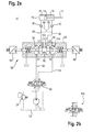
  • Figur 2a einen hydraulischen Schaltplan mit einem Sperrventil gemäß einem zweiten Ausführungsbeispiel;
  • Figur 2b einen Ausschnitt des hydraulischen Schaltplans auf Figur 2a mit einem abgewandelten Stromregelventil;
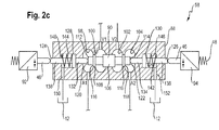
  • Figur 2c in einer vergrößerten schematischen Darstellung das Sperrventil aus Figur 2a;
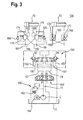
  • Figur 3 einen hydraulischen Schaltplan mit dem Sperrventil gemäß einem dritten Ausführungsbeispiel;
  • Figur 4 in einer Draufsicht das Sperrventil gemäß dem dritten Ausführungsbeispiel;
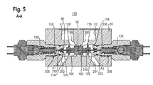
  • Figur 5 in einer Längsschnittansicht das Sperrventil gemäß dem dritten Ausführungsbeispiel;
  • Figur 6 in einer Längsschnittansicht das Sperrventil gemäß dem dritten Ausführungsbeispiel;
  • Figur 7 einen hydraulischen Schaltplan mit dem Sperrventil gemäß einem vierten Ausführungsbeispiel;
  • Figur 8 in einer Längsschnittansicht das Sperrventil gemäß dem vierten Ausführungsbeispiel;
  • Figur 9 einen hydraulischen Schaltplan mit einem Sperrventil gemäß dem dritten Ausführungsbeispiel;
  • Figur 10 in einer Längsschnittansicht das Sperrventil gemäß dem vierten Ausführungsbeispiel.
In the following the invention will be explained in more detail with reference to schematic drawings. Show it:
  • FIG. 1 a hydraulic circuit diagram with a check valve according to the invention according to a first embodiment;
  • FIG. 2a a hydraulic circuit diagram with a check valve according to a second embodiment;
  • FIG. 2b a section of the hydraulic circuit diagram FIG. 2a with a modified flow control valve;
  • Figure 2c in an enlarged schematic representation of the check valve FIG. 2a ;
  • FIG. 3 a hydraulic circuit diagram with the check valve according to a third embodiment;
  • FIG. 4 in a plan view of the check valve according to the third embodiment;
  • FIG. 5 in a longitudinal sectional view of the check valve according to the third embodiment;
  • FIG. 6 in a longitudinal sectional view of the check valve according to the third embodiment;
  • FIG. 7 a hydraulic circuit diagram with the check valve according to a fourth embodiment;
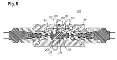
  • FIG. 8 in a longitudinal sectional view of the check valve according to the fourth embodiment;
  • FIG. 9 a hydraulic circuit diagram with a check valve according to the third embodiment;
  • FIG. 10 in a longitudinal sectional view of the check valve according to the fourth embodiment.

Gemäß Figur 1 hat eine hydraulische Anordnung 1 eine Druckmittelquelle in Form einer Hydropumpe 2 und einen von dieser antreibbaren Verbrauchers in Form eines Hydromotors 4. Im Druckmittelströmungspfad zwischen der Hydropumpe 2 und dem Hydromotor 4 ist ein Stromregelventil 6 und ein erfindungsgemäßes Ventil in Form eines Sperrventils 8 angeordnet.According to FIG. 1 a hydraulic arrangement 1 has a pressure medium source in the form of a hydraulic pump 2 and a loadable by this consumer in the form of a hydraulic motor 4. In the pressure fluid flow path between the hydraulic pump 2 and the hydraulic motor 4, a flow control valve 6 and a valve according to the invention in the form of a check valve 8 is arranged.

Die Pumpe 2 fördert über eine Tankleitung 10 Druckmittel von einem Tank 12 in eine Speiseleitung 14. Diese ist an einem Druckanschluss P des Stromregelventils 6 angeschlossen. Bei diesem handelt es sich um ein proportional verstellbares 2/2-Wegeventil, das neben dem Druckanschluss P einen Arbeitsanschluss A aufweist, an den eine Druckmittelleitung 16 angeschlossen ist, die wiederum mit einem Druckanschluss P des Sperrventils 8 verbunden ist. Ein Ventilschieber des Stromregelventils 6 ist über eine Feder 18 in Richtung einer Schließstellung mit einer Federkraft beaufschlagt, wobei in der Schließstellung eine Druckmittelverbindung zwischen den Anschlüssen P und A unterbrochen ist. Über einen Aktuator 20 ist der Ventilschieber dann in seine Schaltstellungen entgegen der Federkraft der Feder 18 bewegbar, bei denen die Druckmittelverbindung zwischen dem Druckanschluss P und den Arbeitsanschluss A geöffnet ist. Mit dem Stromregelventil 6 ist somit ein Druckmittelvolumenstrom des von der Hydropumpe 2 geförderten Druckmittels einstellbar. Zur Druckbegrenzung zweigt von der Speiseleitung 14 zwischen der Hydropumpe 2 und dem Stromregelventil 6 eine Leitung 22 ab, in der ein Druckbegrenzungsventil 24 angeordnet ist, das ab einem vorbestimmten Druck eine Verbindung zum Tank 12 aufsteuert.The pump 2 delivers via a tank line 10 pressure fluid from a tank 12 into a feed line 14. This is connected to a pressure port P of the flow control valve 6. This is a proportional adjustable 2/2-way valve, which in addition to the pressure port P has a working port A, to which a pressure medium line 16 is connected, which in turn is connected to a pressure port P of the check valve 8. A valve spool of the flow control valve 6 is acted upon by a spring 18 in the direction of a closed position with a spring force, wherein in the closed position, a pressure medium connection between the terminals P and A is interrupted. Via an actuator 20, the valve spool is then movable in its switching positions against the spring force of the spring 18, in which the pressure medium connection between the pressure port P and the working port A is opened. With the flow control valve 6 is thus a pressure medium flow rate of the funded by the hydraulic pump 2 pressure medium adjustable. To limit the pressure branches off from the feed line 14 between the hydraulic pump 2 and the flow control valve 6 from a line 22, in which a pressure relief valve 24 is arranged, which opens a connection to the tank 12 from a predetermined pressure.

Das schematisch dargestellte Sperrventil 8 hat einen Ventilkörper in Form eines Ventilschiebers 26, der in einer Ventilbohrung 27 eines Ventilgehäuses 28 gleitend geführt ist. Mit dem Ventilschieber 26 ist eine Druckmittelverbindung zwischen dem Druckanschluss P und einem weiteren Arbeitsanschluss A auf- und zusteuerbar. An den Arbeitsanschluss A ist eine mit dem Hydromotor 4 verbundene Arbeitsleitung 30 angeschlossen, in der ein sich in Strömungsrichtung hin zum Hydromotor 4 öffnendes Rückschlagventil 32 angeordnet ist. Der Ventilschieber 26 ist über eine Federkraft einer Ventilfeder 34 in einer Schließposition, bei der die Druckmittelverbindung zwischen dem Druckanschluss P und dem Arbeitsanschluss A unterbrochen ist, vorgespannt, wobei eine von der Ventilfeder 34 weg weisende Stirnseite 36 des Ventilschiebers 26 an einem Bohrungsgrund der Ventilbohrung 27 im Wesentlichen anliegt. Der Druckanschluss P und der Arbeitsanschluss A münden etwa radial in der Ventilbohrung 27 und sind in der Figur 1 etwa in einer gleichen Ebene etwa senkrecht zu einer Längsachse des Ventilschiebers 26 ausgebildet. In der in der Figur 1 dargestellten Schließposition des Ventilschiebers 26 verschließt dessen Außenmantelfläche den Arbeitsanschluss A und Druckmittelanschluss P. Die Stirnseite 36 ist über einen im Ventilgehäuse 28 eingebrachten Steuerkanal 38 mit Druckmittel vom Druckanschlusses P beaufschlagbar, wobei sich der Ventilschieber 26 dann bei einen die Federkraft der Ventilfeder 34 übersteigenden auf die Stirnfläche 36 wirkenden Steuerdruck sich in eine Öffnungsrichtung entgegen der auf ihn wirkenden Federkraft bewegt. Hierbei wird dann eine Druckmittelverbindung zwischen dem Druckanschluss P und dem Arbeitsanschluss A aufgesteuert. Das Sperrventil 8 kann somit nur vom Druckmittel stromaufwärts des Ventilschiebers 26 beaufschlagt werden.The schematically illustrated check valve 8 has a valve body in the form of a valve spool 26 which is slidably guided in a valve bore 27 of a valve housing 28. With the valve spool 26 is a pressure fluid connection between the pressure port P and another working port A up and zusteuerbar. To the working port A connected to the hydraulic motor 4 working line 30 is connected, in which a in the flow direction to the hydraulic motor 4 opening check valve 32 is arranged. The valve spool 26 is biased via a spring force of a valve spring 34 in a closed position in which the pressure medium connection between the pressure port P and the working port A is interrupted, wherein one of the valve spring 34 facing away end face 36 of the valve spool 26 at a bore bottom of the valve bore 27 is substantially present. The pressure port P and the working port A open approximately radially in the valve bore 27 and are in the FIG. 1 formed approximately in a same plane approximately perpendicular to a longitudinal axis of the valve spool 26. In the in the FIG. 1 The outer side surface closes the working port A and the pressure medium connection P. The end 36 is acted upon by a pressure in the valve housing 28 pressure medium from the pressure port P, wherein the valve spool 26 then at a spring force of the valve spring 34 on the over End face 36 acting control pressure moves in an opening direction against the spring force acting on it. Here then a pressure fluid connection between the pressure port P and the working port A is opened. The check valve 8 can thus be acted upon only by the pressure medium upstream of the valve spool 26.

Der Ventilschieber 26 hat einen von seiner Stirnfläche 36 weg weisenden radial zurückgestuften Ventilschieberabschnitt 40, der durch das Ventilgehäuse 28 nach außen geführt ist. Der Ventilschieber 26 begrenzt mit seiner Stirnseite 36 im Ventilgehäuse 28 einen Zylinderraum und mit seinem Ventilschieberabschnitt 40 einen die Ventilfeder 34 aufweisenden Ringraum 42. Mit dem Ventilschieberabschnitt 40 ist ein außerhalb des Ventilgehäuses 28 angeordneter Sensor 44 betätigbar. Bei diesem handelt es sich um einen herkömmlichen vorrichtungstechnisch einfach aufgebauten elektrischen Taster oder elektrischen Schalter.The valve spool 26 has a radially back-stepped valve spool portion 40 facing away from its end surface 36, which is guided through the valve housing 28 to the outside. The valve spool 26 defines with its end face 36 in the valve housing 28 a cylinder space and with its valve spool portion 40 a valve spring 34 having annular space 42. With the valve spool portion 40 is arranged outside the valve housing 28 sensor 44 can be actuated. This is a conventional device constructed simple electrical button or electrical switch.

Durch den Sensor 44 kann auf äußerst einfache Weise die Neutralstellung bzw. die Schließstellung des Ventilschiebers 26 festgestellt werden, in der der Druckanschluss P vom Arbeitsanschluss A fluidisch getrennt ist. Der Sensor 44 hat ein stabförmig aufgebautes Betätigungselement 46, das in der in Figur 1 gezeigten Position im Kontakt oder nahezu im Kontakt mit einer Stirnseite des Ventilschieberabschnitts 40 und somit mit dem Ventilschieber 26 mechanisch in Kontakt bringbar ist. Bei einer Verschiebung des Ventilschiebers 26 aus seiner in der Figur 1 gezeigten Neutralstellung in Richtung seiner Öffnungs- beziehungsweise Schaltstellungen wird das Betätigungselement 46 über den Ventilschieberabschnitt 40 ebenfalls in diese Richtung bewegt, wodurch der Sensor 44 betätigt wird und ein Schaltsignal beispielsweise an eine Electronic Control Unit meldet. Wird der Ventilschieber 26 in Richtung seiner Neutral- beziehungsweise Schließstellung bewegt, so wird das Betätigungselement 46 durch eine Sensorfeder 48 des Sensors 44 ebenfalls in diese Richtung verschoben. Ist der Ventilschieber 26 in der in Figur 1 gezeigten Schließstellung, dann ist das Betätigungselement 46 in einer Position, in der der Sensor 44 ausgeschaltet ist.By the sensor 44, the neutral position or the closed position of the valve spool 26 can be determined in an extremely simple manner, in which the pressure port P is fluidly separated from the working port A. The sensor 44 has a rod-shaped actuator 46, which in the in FIG. 1 shown position in contact or almost in contact with an end face of the valve spool portion 40 and thus mechanically engageable with the valve spool 26. Upon a displacement of the valve spool 26 from its in the FIG. 1 shown neutral position in the direction of its opening or switching positions, the actuating element 46 is also moved via the valve spool portion 40 in this direction, whereby the sensor 44 is actuated and reports a switching signal, for example, to an electronic control unit. If the valve spool 26 is moved in the direction of its neutral or closed position, the actuating element 46 is likewise displaced in this direction by a sensor spring 48 of the sensor 44. Is the valve spool 26 in the in FIG. 1 shown closed position, then the actuator 46 is in a position in which the sensor 44 is turned off.

Im Ventilgehäuse 28 des Sperrventils 8 ist des Weiteren ein Leckageanschluss 50 vorgesehen, der mit der Ventilbohrung 27 im Bereich des von dem Ventilschieber 26 begrenzten Ringraums 42 verbunden ist und über eine Tankleitung 52 an den Tank 12 angeschlossen ist. Der Hydromotor 4 ist ausgangsseitig über eine Ablaufleitung 54 ebenfalls mit dem Tank 12 verbunden.In the valve housing 28 of the check valve 8, a leakage connection 50 is further provided, which is connected to the valve bore 27 in the region of the valve slide 26 limited annular space 42 and is connected via a tank line 52 to the tank 12. The hydraulic motor 4 is also connected on the output side via a drain line 54 to the tank 12.

Figur 2a zeigt eine weitere hydraulische Anordnung 56 mit einem erfindungsgemäßen Ventil 58. Im Unterschied zur Figur 1 ist das Stromregelventil 60 als proportional verstellbares 4/3-Wegeventil ausgebildet, das einen Druckanschluss P, einen Tankanschluss T und zwei Arbeitsanschlüsse A, B aufweist. An den Arbeitsanschluss A des Stromregelventils 60 ist eine erste Verbindungsleitung 62 angeschlossen, die mit einem Anschluss A1 des unterschiedlich zur Figur 1 ausgebildeten Sperrventils 58 verbunden ist und an den Arbeitsanschluss B ist eine zweite Verbindungsleitung 64 angeschlossen, die mit einem Anschluss A2 des Sperrventils 58 verbunden ist. Des Weiteren hat das Sperrventil 58 einen ersten Verbraucheranschluss V1, an dem eine erste Verbraucherleitung 66 angeschlossen ist, und einen zweiten Verbraucheranschluss V2, an dem eine zweite Verbraucherleitung 68 angeschlossen ist. Als Verbraucher ist ein Differentialzylinder 70 mit einem einseitig eine Kolbenstange 72 aufweisenden Kolben 74 vorgesehen. Der Kolben 74 trennt somit einen Zylinderraum 76 von einem Ringraum 78. In einer jeweiligen Verbraucherleitung 66 und 68 ist ein in Druckmittelströmungsrichtung hin zum Differentialzylinder 70 sich öffnendes Rückschlagventil 80 beziehungsweise 82 angeordnet. Zum Entsperren ist das Rückschlagventil 80 über eine Steuerleitung 84 mit der Verbraucherleitung zwischen dem Sperrventil 58 und dem Rückschlagventil 82 verbunden. Zum Entsperren des Rückschlagventils 82 ist wiederum eine Steuerleitung 86 vorgesehen, die an die Verbraucherleitung 66 zwischen dem Rückschlagventil 80 und dem Sperrventil 58 abzweigt. FIG. 2a shows a further hydraulic arrangement 56 with a valve 58 according to the invention. In contrast to FIG. 1 the flow control valve 60 is designed as a proportionally adjustable 4/3-way valve having a pressure port P, a tank port T and two working ports A, B. To the working port A of the flow control valve 60, a first connecting line 62 is connected to a port A1 of the different FIG. 1 trained blocking valve 58 is connected and to the working port B, a second connecting line 64 is connected, which is connected to a port A2 of the check valve 58. Furthermore, the check valve 58 has a first consumer port V1, to which a first consumer line 66 is connected, and a second consumer port V2, to which a second consumer line 68 is connected. As a consumer, a differential cylinder 70 is provided with a one-sided piston rod 72 having a piston 74. The piston 74 thus separates a cylinder chamber 76 from an annular space 78. In a respective consumer line 66 and 68, a check valve 80 or 82 opening in the direction of the pressure medium flow toward the differential cylinder 70 is arranged. To unlock the check valve 80 is connected via a control line 84 to the consumer line between the check valve 58 and the check valve 82. To unlock the check valve 82, in turn, a control line 86 is provided, which branches off to the consumer line 66 between the check valve 80 and the check valve 58.

An den Druckanschluss P des Stromregelventils 60 ist entsprechend der hydraulischen Anordnung 1 aus Figur 1 die Hydropumpe 2 angeschlossen und es ist auch das Druckbegrenzungsventil 24 vorgesehen, mit dem eine Verbindung zum Tank12 aufsteuerbar ist.To the pressure port P of the flow control valve 60 is corresponding to the hydraulic arrangement 1 off FIG. 1 connected to the hydraulic pump 2 and it is also the pressure relief valve 24 is provided, with a connection to the tank 12 can be opened.

Das Stromregelventil 60 hat einen Ventilschieber, der aus seiner Neutralstellung, bei der eine Druckmittelverbindung zwischen den Anschlüssen A, B, P und T unterbrochen ist, über Aktuatoren in Richtung von ersten und in Richtung von zweiten Schaltstellungen verschiebbar ist, wobei die Richtungen einander entgegengesetzt sind. In Richtung der ersten Schaltstellungen a ist die Druckmittelverbindung zwischen dem Druckanschluss P und dem Arbeitsanschluss A und zwischen dem Tankanschluss T und dem Arbeitsanschluss B aufgesteuert, während in der zweiten Schaltstellung b eine Druckmittelverbindung zwischen dem Druckanschluss P und dem Arbeitsanschluss B und zwischen dem Arbeitsanschluss A und dem Tankanschluss T aufgesteuert ist. Des Weiteren ist der Ventilschieber in seiner Neutralstellung 0 federzentriert.The flow control valve 60 has a valve spool, which is displaceable from its neutral position, in which a pressure medium connection between the terminals A, B, P and T is interrupted, via actuators in the direction of first and in the direction of second switching positions, wherein the directions are opposite to each other , In the direction of the first switching positions a, the pressure medium connection between the pressure port P and the working port A and between the tank port T and the working port B is opened, while in the second switching position b a pressure medium connection between the pressure port P and the working port B and between the working port A and the tank connection T is turned on. Furthermore, the valve spool is spring-centered in its neutral position 0.

Das Sperrventil 58 hat im Unterschied zum Sperrventil 8 aus Figur 1 einen in einem Ventilgehäuse 88 geführten Ventilschieber 90, der aus einer in der Figur 2a dargestellten Neutralstellung in Richtung von ersten und zweiten Schaltstellungen verschiebbar ist, wobei die Richtungen entgegengesetzt sind. Zum Erfassen der Neutralstellung des Ventilschiebers 90 und zum Erfassen seiner Verschieberichtung aus der Neutralstellung sind Sensoren 92 und 94 vorgesehen, die entsprechend dem Sensor aus der Figur 1 als vorrichtungstechnisch äußerst einfach aufgebaute elektrische Taster oder elektrische Schalter ausgestaltet sind. Der Ventilschieber 90 ist hierbei in einer Ventilbohrung 92 gleitend geführt, in der vier in Längsrichtung der Ventilbohrung 92 zueinander beabstandete Ringkammern 98, 100, 102 und 104 ausgebildet sind. Zur besseren Erläuterung des Sperrventils 58 ist dieses in der Figur 2c vergrößert dargestellt.The check valve 58 has in contrast to the check valve 8 FIG. 1 a guided in a valve housing 88 valve spool 90, which consists of a in the FIG. 2a shown neutral position in the direction of first and second switching positions is displaceable, the directions are opposite. For detecting the neutral position of the valve spool 90 and for detecting its direction of displacement from the neutral position, sensors 92 and 94 are provided, which correspond to the sensor from the FIG. 1 are designed as a device extremely simple design electrical button or electrical switch. The valve spool 90 is in this case slidably guided in a valve bore 92 in which four in the longitudinal direction of the valve bore 92 to each other spaced annular chambers 98, 100, 102 and 104 are formed. For a better explanation of the check valve 58, this is in the Figure 2c shown enlarged.

Die Ringkammer 98 in Figur 2c ist hierbei mit dem Anschluss A1, die von ihr benachbarte Ringkammer 100 mit dem Anschluss V1, die nächste Kammer 102 mit dem Anschluss V2 und die äußere Kammer 104 mit dem Anschluss A2 verbunden. Die beiden mittleren Kammern 100 und 102 sind in jeder Stellung des Ventilschiebers 90 durch dessen mittleren Radialbund 106 voneinander getrennt. Des Weiteren hat der Ventilschieber 90 einen, in der Figur 2c vom mittleren Radialbund 106 aus gesehen, linken Radialbund 108 und einen rechten Radialbund 110. Mit dem linken Radialbund 108 ist dabei in der Neutralstellung des Ventilschiebers 90 eine Druckmittelverbindung zwischen den Ringkammern 98 und 100 zugesteuert, während sowohl in den ersten als auch in den zweiten Schaltstellungen des Ventilschiebers 90 eine Druckmittelverbindung zwischen den Ringkammern 98 und 100 aufgesteuert ist. Mit dem rechten Radialbund 110 ist dagegen in der Neutralstellung des Ventilschiebers 90 eine Druckmittelverbindung zwischen den Ringkammern 102 und 104 zugesteuert und in den Schaltstellungen des Ventilschiebers 90 aufgesteuert.The annular chamber 98 in Figure 2c In this case, it is connected to the connection A1, the annular chamber 100 adjacent to it to the connection V1, the next chamber 102 to the connection V2, and the outer chamber 104 to the connection A2. The two middle chambers 100 and 102 are in each position of the valve spool 90 through its central radial collar 106 separated from each other. Furthermore, the valve spool 90 has a, in the Figure 2c seen from the central radial collar 106, left radial collar 108 and a right radial collar 110. With the left radial collar 108 is in the neutral position of the valve spool 90 a pressure medium connection between the annular chambers 98 and 100 controlled, while both in the first and in the second switching positions the valve spool 90, a pressure medium connection between the annular chambers 98 and 100 is opened. With the right radial collar 110, however, in the neutral position of the valve slide 90, a pressure medium connection between the annular chambers 102 and 104 is controlled and opened in the switching positions of the valve slide 90.

Der Ventilschieber 90 ist an seinen Endabschnitten 112 und 114 radial zurückgestuft und weist jeweils eine durch den Radialbund 108 und dem Endabschnitt 112 und dem Radialbund 110 und dem Endabschnitt 114 gebildete Ringstirnfläche 116 beziehungsweise 118 auf. Des Weiteren hat der Ventilschieber 90 jeweils an seinem Endabschnitt 112 und 114 ausgebildete Stirnfläche 120 beziehungsweise 122.The valve spool 90 is radially stepped back at its end portions 112 and 114 and each has an annular end surface 116 and 118 formed by the radial collar 108 and the end portion 112 and the radial collar 110 and the end portion 114, respectively. Furthermore, the valve slide 90 has end faces 120 and 122 respectively formed on its end section 112 and 114.

Der Ventilschieber 90 betätigt bei einer Verschiebung aus seiner in der Figur 2c gezeigten Neutralstellung nach links über einen koaxial zum ihm angeordnete Detektionskolben 124 den Sensor 92 und bei einer Verschiebung nach rechts über einen weiter Detektionskolben 126 den Sensor 94. Ein jeweiliger Detektionskolben 124 und 126 weist einen Radialbund 128 beziehungsweise 130 auf, der jeweils etwa im mittleren Bereich des Detektionskolbens 124 beziehungsweise 126 ausgebildet ist. Vom Radialbund 128 und 130 eines jeweiligen Detektionskolbens 124 beziehungsweise 126 erstreckt sich jeweils zum Ventilschieber 90 ein Kolbenabschnitt 132 beziehungsweise 134. Eine jeweilige zum Ventilschieber 90 weisende Stirnfläche des Kolbenabschnitts 132 beziehungsweise 134 ist im Wesentlichen kuppelförmig ausgebildet und stützt sich in der Neutralstellung des Ventilschiebers 90 an dessen jeweiliger Stirnfläche 120 beziehungsweise 122 ab. Die Kolbenabschnitte 132 und 134 kragen dabei in die Ringkammer 98 beziehungsweise 104 ein. Des Weiteren erstreckt sich von einem jeweiligen Radialbund 128 und 130 aus, weg von dem Ventilschieber 90, ein weiterer Kolbenabschnitt 136 beziehungsweise 138. Diese begrenzen dabei jeweils im Ventilgehäuse 88 einen ringförmigen Federraum 140 beziehungsweise 142 und erstrecken sich durch das Ventilgehäuse 88 nach außen zum Betätigen eines jeweiligen Betätigungselements 46 des Sensors 92 beziehungsweise 94. In dem jeweiligen Federraum 140 und 142 ist eine Ventilfeder 144 beziehungsweise 146 angeordnet, die den jeweiligen Kolbenabschnitt 136 beziehungsweise 138 umgreift, sich jeweils am Ventilgehäuse 88 abstützt und den jeweiligen Radialbund 128 beziehungsweise 130 mit einer Federkraft in Richtung des Ventilschiebers 90 beaufschlagt. Der Ventilschieber 90 wird dann über die Ventilfeder 144 beziehungsweise 146 in seiner Neutralstellung federzentriert. Die Federräume 140 und 142 sind jeweils über einen Leckagekanal 150 beziehungsweise 152 mit dem Tank 12 verbunden.The valve spool 90 is actuated at a shift from his in the Figure 2c shown neutral position to the left via a coaxially to the detection piston 124 arranged thereon the sensor 92 and a shift to the right via a further detection piston 126, the sensor 94. A respective detection piston 124 and 126 has a radial collar 128 and 130, each about in the central region the detection piston 124 or 126 is formed. A respective piston section 132 or 134 extends from the radial collar 128 and 130 of a respective detection piston 124 or 126 to the valve spool 90. A respective end face of the piston section 132 or 134 facing the valve spool 90 has a substantially dome-shaped configuration and rests in the neutral position of the valve spool 90 its respective end face 120 and 122 from. The piston portions 132 and 134 thereby collar into the annular chamber 98 and 104, respectively. Furthermore, extending from a respective radial collar 128 and 130, away from the valve spool 90, another piston portion 136 and 138. These limit each case in the valve housing 88 an annular spring chamber 140 and 142 and extend through the Valve housing 88 outwardly for actuating a respective actuating element 46 of the sensor 92 and 94. In the respective spring chamber 140 and 142, a valve spring 144 and 146 is arranged, which surrounds the respective piston portion 136 and 138, respectively supported on the valve housing 88 and the respective radial collar 128 and 130 acted upon by a spring force in the direction of the valve spool 90. The valve spool 90 is then spring-centered via the valve spring 144 or 146 in its neutral position. The spring chambers 140 and 142 are each connected to the tank 12 via a leakage channel 150 or 152.

Die Funktionsweise des Sperrventils 58 wird nun anhand der Figuren 2a und 2c erläutert. Durch das Stromregelventil 60 ist entweder der Anschluss A1 oder A2 mit der Hydropumpe 2 verbindbar, während der jeweils andere mit dem Tank 12 verbunden ist. Wird der Anschluss A1 mit der Hydropumpe 2 verbunden, das heißt das Stromregelventil 60 befindet sich in seinen Schaltstelllungen a, dann baut sich in der Ringkammer 98 des Sperrventils 58 durch ein darin hinein befördertes Druckmittel ein Druck auf, wodurch auf den Ventilschieber 90 über seine zur Ringkammer 98 weisende Ringstirnfläche 116 und Stirnfläche 120 eine Druckkraft wirkt. Die andere Ringkammer 104 ist dagegen zum Tank 12 entlastet. Übersteigt die auf den Ventilschieber 90 wirkende Druckkraft die Federkraft der Ventilfeder 146, dann verschiebt sich der Ventilschieber 90 in seine Schaltstellungen, in denen eine Druckmittelverbindung zwischen den Anschlüssen A1 und V1 und zwischen den Anschlüssen V2 und A2 aufgesteuert ist. Stromabwärts des Anschlusses V1 des Sperrventils 58 werden dann die Rückschlagventile 80 und 82 geöffnet, wobei dann der Zylinderraum 76 mit der Hydropumpe 2 und der Ringraum 78 mit dem Tank 12 in Druckmittelverbindung stehen. Beim Verschieben des Ventilschiebers 90 des Sperrventils 58 in die beschriebene Schaltstellung wird der Detektionskolben 126 ebenfalls bewegt, indem die Stirnfläche 122 des Ventilschiebers 90 an die Stirnfläche des Kolbenabschnitts 134 anliegt. Die Verschiebung des Detektionskolbens 126 erfolgt dabei ebenfalls entgegen der Federkraft der Ventilfeder 146 in Richtung zum Betätigungselement 46. Da dieses an einer Stirnfläche des Kolbenabschnitts 138 anliegt wird es in Richtung des Sensors 94 bewegt, wodurch dieser betätigt ist. Der andere Sensor 92 bleibt unbetätigt, da der Detektionskolben 124 durch dem ihm zugeordnete Ventilfeder 144 in seiner Endposition verbleibt, in der der Radialbund 128 an einer Ringfläche des Ventilgehäuses 58 im Wesentlichen anliegt. Da nur der Sensor 94 betätigt ist, kann daraus geschlossen werden, dass der Ventilschieber 90 in dessen Richtung aus seiner Neutralstellung verschoben ist.The operation of the check valve 58 will now be described with reference to FIGS. 2a and 2c explained. By the flow control valve 60 either the port A1 or A2 with the hydraulic pump 2 is connectable, while the other is connected to the tank 12. If the port A1 connected to the hydraulic pump 2, that is, the flow control valve 60 is in its switching positions a, then builds up in the annular chamber 98 of the check valve 58 by a therein conveyed pressure fluid pressure, causing the valve spool 90 via his to Ring chamber 98 facing annular end face 116 and end face 120 acts a compressive force. The other annular chamber 104, however, is relieved to the tank 12. If the pressure force acting on the valve spool 90 exceeds the spring force of the valve spring 146, the valve spool 90 shifts into its switching positions in which a pressure medium connection between the ports A1 and V1 and between the ports V2 and A2 is opened. Downstream of the connection V1 of the check valve 58 then the check valves 80 and 82 are opened, in which case the cylinder chamber 76 with the hydraulic pump 2 and the annular space 78 with the tank 12 are in fluid communication. When moving the valve spool 90 of the check valve 58 in the switching position described, the detection piston 126 is also moved by the end face 122 of the valve spool 90 abuts the end face of the piston portion 134. The displacement of the detection piston 126 also takes place counter to the spring force of the valve spring 146 in the direction of the actuating element 46. Since this rests against an end face of the piston portion 138, it is moved in the direction of the sensor 94, whereby it is actuated. The other sensor 92 remains unconfirmed because the detection piston 124 remains in its end position by the valve spring 144 assigned to it, in which the radial collar 128 abuts an annular surface of the valve housing 58 substantially abuts. Since only the sensor 94 is actuated, it can be concluded that the valve spool 90 is displaced in its direction from its neutral position.

Wird die Druckmittelverbindung zwischen dem Sperrventil 58 und der Hydropumpe 2 durch eine Verstellung des Ventilschiebers des Stromregelventils 60 in seine Neutralstellung unterbrochen, dann fließt Druckmittel aus der Ringkammer 98 als Leckage zum Tank 12 ab, wodurch sich ein Druck in dieser Kammer 98 verringert. Die Rückschlagventile 80 und 82 werden verschlossen, wodurch der Differentialzylinder 70 in seiner Position im Wesentlichen verbleibt. Sinkt der Druck im Ringraum 98 so weit ab, dass die auf den Ventilschieber 90 entgegen der Federkraft der Ventilfeder 146 wirkende Druckkraft kleiner als die Federkraft ist, dann wird der Ventilschieber 90 durch die Ventilfeder 146 und dem Detektionskolben 126 in seine Neutralstellung verschoben. Erreicht der Ventilschieber 90 seine Neutralstellung dann ist das Betätigungselement 46 des Sensors 94 durch die Sensorfeder 48 ebenfalls wieder in seiner Ausgangsposition, in der der Sensor 94 unbetätigt ist. Da der Sensor 92 in der Neutralstellung des Ventilschiebers 90 ebenfalls unbestätigt ist, ist somit auf einfache Weise daraus schließbar, dass sich der Ventilschieber 90 ebenfalls in seiner Neutralstellung befindet.If the fluid connection between the check valve 58 and the hydraulic pump 2 is interrupted by an adjustment of the valve spool of the flow control valve 60 in its neutral position, then pressure fluid flows from the annular chamber 98 as leakage to the tank 12, whereby a pressure in this chamber 98 is reduced. The check valves 80 and 82 are closed, leaving the differential cylinder 70 in position substantially. If the pressure in the annular space 98 decreases to such an extent that the pressure force acting on the valve spool 90 against the spring force of the valve spring 146 is smaller than the spring force, then the valve spool 90 is displaced by the valve spring 146 and the detection piston 126 into its neutral position. When the valve spool 90 reaches its neutral position, the actuating element 46 of the sensor 94 is likewise returned to its initial position by the sensor spring 48, in which the sensor 94 is unactuated. Since the sensor 92 is also unconfirmed in the neutral position of the valve spool 90, it can thus be concluded in a simple manner that the valve spool 90 is also in its neutral position.

Bei einer Verschiebung des Ventilschiebers des Stromregelventils 60 in die Schaltstellungen b ist die Ringkammer 104 mit der Hydropumpe 2 und die Ringkammer 98 mit dem Tank 12 verbunden. Hierbei wird der Ventilschieber 90 bei entsprechenden Druckverhältnissen in seine Schaltstellungen in den Figuren nach links verschoben, wodurch wiederum der Sensor 92 über den Detektionskolben 132 betätigt ist. Der Sensor 94 bleibt unbetätigt. In den Schaltstellungen des Ventilschiebers 90 ist der Anschluss A2 mit dem Anschluss V1 und der Anschluss A1 mit dem Anschluss V1 verbunden. Sinkt der Druck in der Ringkammer 104 ab, nachdem der Ventilschieber des Stromregelventils 60 in seine Neutralstellung 0 verschoben ist, so wird der Ventilschieber 90 wieder in seine Neutralstellung federzentriert, und der Sensor 92 ist wieder unbetätigt.Upon a displacement of the valve spool of the flow control valve 60 in the switching positions b, the annular chamber 104 is connected to the hydraulic pump 2 and the annular chamber 98 to the tank 12. Here, the valve spool 90 is shifted at appropriate pressure ratios in its switching positions in the figures to the left, which in turn the sensor 92 is actuated via the detection piston 132. The sensor 94 remains unconfirmed. In the switching positions of the valve spool 90, the port A2 is connected to the port V1 and the port A1 to the port V1. If the pressure in the annular chamber 104 decreases after the valve spool of the flow control valve 60 has been shifted to its neutral position 0, the valve spool 90 is spring-centered again into its neutral position, and the sensor 92 is again inactive.

Ein Durchmesser der zum Ventilschieber 90 weisenden Kolbenabschnitte 132 und 134 des Detektionskolbens 124 beziehungsweise 126 ist dabei derart gewählt, dass eine auf ihn wirkende Druckkraft aufgrund eines Drucks in der Ringkammer 98 beziehungsweise 104 kleiner als die Federkraft der Ventilfeder 144 beziehungsweise 146 ist, damit der Detektionskolben 124 beziehungsweise 126 nur durch den Ventilschieber 90 verschiebbar ist.A diameter of the valve spool 90 facing piston portions 132 and 134 of the detection piston 124 and 126 is selected such that a pressure force acting on it due to a pressure in the annular chamber 98 and 104 is smaller than the spring force of the valve spring 144 or 146, so that the detection piston 124 or 126 is displaceable only by the valve spool 90.

Zur Bestimmung der Neutralstellung des Ventilschiebers 90 können die Sensoren 92 und 94 vorteilhafter Weise eine vergleichsweise geringe Präzision aufweisen, wodurch einfache Schalter als Vorrichtung zur Positionserfassung ausreichend sind, was zu einem äußerst kostengünstigen Ventil mit Positionsüberwachung führt.To determine the neutral position of the valve spool 90, the sensors 92 and 94 advantageously have a comparatively low precision, whereby simple switches are sufficient as a device for position detection, resulting in a very cost-effective valve with position monitoring.

In der Figur 2b ist ein Stromregelventil 154 als Variante zum Stromregelventil 60 aus Figur 2a gezeigt. Dieses hat im Unterschied zum Stromregelventil 60 eine Neutralstellung 0, bei der die Arbeitsanschlüsse A und B jeweils gedrosselt mit dem Tankanschluss T verbunden sind. Hierdurch kann in der Neutralstellung des Stromregelventils 154 Druckmittel insbesondere aus den Ringkammern 98 und 104 des Sperrventils 58 zum Tank 12 fließen.In the FIG. 2b is a flow control valve 154 as a variant of the flow control valve 60 FIG. 2a shown. This has, in contrast to the flow control valve 60, a neutral position 0, in which the working ports A and B are each throttled connected to the tank port T. As a result, in the neutral position of the flow control valve 154, pressure medium, in particular from the annular chambers 98 and 104 of the check valve 58, can flow to the tank 12.

Gemäß Figur 3 hat die hydraulische Anordnung 156 ein sich von der Figur 2b unterscheidendes Stromregelventil 158. Die Verbindungen zwischen dem Druckanschluss P und dem Arbeitsanschluss A oder B sind hierbei jeweils gedrosselt. Des Weiteren zweigt von der Speiseleitung 14 ein Kanal mit einem Druckbegrenzungsventil 160 ab, deren Federkraft der Ventilfeder 162 im Unterschied zu den vorhergehenden Ausführungsformen einstellbar ist. In der Figur 3 ist zusätzlich ein die Hydropumpe 2 antreibender Motor 164 dargestellt.According to FIG. 3 the hydraulic assembly 156 is separate from the FIG. 2b differing flow control valve 158. The connections between the pressure port P and the working port A or B are in each case throttled. Furthermore, branches off from the feed line 14, a channel with a pressure relief valve 160, the spring force of the valve spring 162 is adjustable in contrast to the previous embodiments. In the FIG. 3 In addition, a hydraulic pump 2 driving motor 164 is shown.

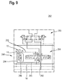
Das Sperrventil 193 ist gemäß einem weiteren Ausführungsbeispiel als Blockschaltbild in der Figur 3 dargestellt. Stromabwärts des Sperrventils 58 sind in der Figur 3 zwei unterschiedliche Variationen zum Anschluss des Differenzialzylinders 70 vorgesehen. Die rechte Variation weist im Unterschied zur Ausführungsform in der Figur 2a Rückschlagventile 166 und 168 auf, deren Ventilkörper jeweils über eine Feder 170 beziehungsweise 172 mit einer Federkraft in Richtung ihrer Schließrichtung beaufschlagt sind. In der zweiten Variante, links in der Figur 3 ist parallel zu einem jeweiligen Rückschlagventil 166 und 168 ein Ventil 174 beziehungsweise 176 vorgesehen. Hierbei handelt es sich jeweils um ein proportional 2/2-Wegeventil. Ein Ventilschieber des jeweiligen Ventils 174 und 176 ist dabei über eine Federkraft einer Feder in Schließrichtung beaufschlagt. Auf den jeweiligen Ventilschieber des Ventils 174 beziehungsweise 176 wirkt zusätzlich in Schließrichtung der Druck der ihm zugeordneten Verbraucherleitung 66 beziehungsweise 68 zwischen Sperrventil 193 und dem jeweiligen Ventil 174 beziehungsweise 176, wofür jeweils eine von der Verbraucherleitung 66 beziehungsweise 68 abzweigende Steuerleitung 178 beziehungsweise 180 vorgesehen ist. In Öffnungsrichtung wird ein jeweiliger Ventilschieber des Ventils 174 beziehungsweise 176 über eine Steuerleitung 182 beziehungsweise 184 vom Druck zwischen einem jeweiligen Ventil 174 beziehungsweise 176 und dem Differentialzylinder 70 beaufschlagt. Des Weiteren wird der Ventilschieber des rechten Ventils 176 in seiner Öffnungsrichtung über eine Steuerleitung 186 vom Druck der Verbraucherleitung 66 zwischen Sperrventil 193 und dem linken Ventil 174 und der Ventilschieber des linken Ventils 174 in seiner Öffnungsrichtung über die Steuerleitung 188 vom Druck der Verbraucherleitung 68 zwischen Sperrventil 193 und dem rechten Ventil 176 beaufschlagt.The check valve 193 is according to another embodiment as a block diagram in the FIG. 3 shown. Downstream of the check valve 58 are in the FIG. 3 two different variations for connection of the differential cylinder 70 is provided. The right variation, unlike the embodiment in the FIG. 2a Check valves 166 and 168, the valve body are each acted upon by a spring 170 and 172 with a spring force in the direction of its closing direction. In the second variant, left in the FIG. 3 is provided in parallel to a respective check valve 166 and 168, a valve 174 and 176, respectively. These are each a proportional 2/2-way valve. A valve spool of the respective valve 174 and 176 is acted upon via a spring force of a spring in the closing direction. On the respective valve spool of the valve 174 or 176 additionally acts in the closing direction, the pressure of its associated consumer line 66 or 68 between the check valve 193 and the respective valve 174 and 176, respectively, for each of which a branch of the consumer line 66 and 68 control line 178 and 180 is provided. In the opening direction, a respective valve slide of the valve 174 or 176 is acted upon by a pressure between a respective valve 174 or 176 and the differential cylinder 70 via a control line 182 or 184. Further, the valve spool of the right valve 176 in its opening direction via a control line 186 from the pressure of the consumer line 66 between check valve 193 and the left valve 174 and the valve spool of the left valve 174 in its opening direction via the control line 188 from the pressure of the consumer line 68 between check valve 193 and the right valve 176 acted upon.

Das Blockschaltbild des Sperrventils 193 zeigt schematisch die Sensoren 92 und 94 die vom Ventilschieber des Sperrventils 193 betätigbar sind. Des Weiteren sind die im Tank 12 mündenden Leckagekanäle 150, 152 dargestellt. Eine Druckbeaufschlagung des Ventilschiebers des Sperrventils 193 erfolgt durch die Steuerleitungen 190 beziehungsweise 192, die jeweils von der Verbindungsleitung 62 beziehungsweise 64 abzweigen.The block diagram of the check valve 193 schematically shows the sensors 92 and 94 which are actuated by the valve spool of the check valve 193. Furthermore, the leakage channels 150, 152 opening in the tank 12 are shown. A pressurization of the valve spool of the check valve 193 takes place through the control lines 190 and 192, which branch off respectively from the connecting line 62 and 64 respectively.

In der Darstellung gemäß Figur 4 hat das Sperrventil 193 aus Figur 3 im Ventilgehäuse 88 ausgebildete Arbeitsanschlüsse V1 und V2. Die Sensoren 92 und 94 sind seitlich in das Ventilgehäuse 88 eingeschraubt und weisen jeweils zwei elektrische Kontakte 194 und 196 zur elektrischen Kontaktierung auf.In the illustration according to FIG. 4 has the check valve 193 off FIG. 3 formed in the valve housing 88 working ports V1 and V2. The sensors 92 and 94 are laterally screwed into the valve housing 88 and each have two electrical contacts 194 and 196 for electrical contacting.

Figur 5 zeigt in einer Längsschnittansicht entlang einer Schnittebene A-A aus Figur 4 das Sperrventil 193. Die Arbeitsanschlüsse V1 und V2 sind hierbei als Sacklochbohrungen in das Ventilgehäuse 88 eingebracht. Am Bohrungsgrund eines jeweiligen Anschlusses V1 und V2 führt ein Schrägkanal 198 beziehungsweise 200 zur Ringkammer 100 beziehungsweise 102. Die Anschlüsse A1 und A2 sind als Schrägkanäle 202 beziehungsweise 204 in das Ventilgehäuse 88 eingebracht und münden jeweils im Ringkanal 98 beziehungsweise 104. Im Unterschied zum Sperrventil 58 aus der Figur 2c ist ein jeweiliger Detektionskolben 206 beziehungsweise 208 zweiteilig ausgestaltet. Hier ist jeweils der vom Radialbund 128 beziehungsweise 130 zum Ventilschieber 90 führende Kolbenabschnitt 210 beziehungsweise 212 einstückig und stabförmig ausgestaltet. Der jeweilige Kolbenabschnitt 210 und 212 kann sich dann mit seiner von dem Ventilschieber 90 weg weisenden Stirnfläche an dem Kolbenabschnitt 136 beziehungsweise 138 abstützen. Jeweils mit seiner zum Ventilschieber 90 weisenden Stirnfläche kann sich der Kolbenabschnitt 210 beziehungsweise 212 an dem Ventilschieber 90 abstützen. Dieser hat im Unterschied zum Sperrventil 58 aus der Figur 2c von seiner jeweiligen Stirnseite 120 beziehungsweise 122 her eingebrachte, sich etwa koaxial zur Längsachse des Ventilschiebers 90 erstreckende Sacklochbohrungen 214 beziehungsweise 216. Eine jeweilige Sacklochbohrung 214 beziehungsweise 216 erstreckt sich dabei etwa bis zum Radialbund 108 beziehungsweise 110 des Ventilschiebers 90 und weist einen größeren Durchmesser als der jeweilige stabförmige Kolbenabschnitt 210 beziehungsweise 212 auf. Durch den zweitteilig aufgebauten Detektionskolben 206 und 208 wird eine statisch überbestimmte Führung vermieden, so dass eine Klemmung des jeweiligen Detektionskolben 206 beziehungsweise 208 im Wesentlichen vermieden ist. FIG. 5 shows in a longitudinal sectional view along a sectional plane AA FIG. 4 the check valve 193. The working ports V1 and V2 are here introduced as blind holes in the valve housing 88. At the bottom of the hole of a respective port V1 and V2 leads a slant channel 198 or 200 to the annular chamber 100 and 102. The ports A1 and A2 are introduced as slanted channels 202 and 204 in the valve housing 88 and open respectively in the annular channel 98 and 104. In contrast to the check valve 58th from the Figure 2c is a respective detection piston 206 or 208 designed in two parts. Here each of the radial collar 128 or 130 leading to the valve spool 90 piston portion 210 and 212 is configured in one piece and rod-shaped. The respective piston section 210 and 212 can then be supported on the piston section 136 or 138 with its end face facing away from the valve slide 90. Each with its facing the valve spool 90 face the piston portion 210 and 212 may be supported on the valve spool 90. This has in contrast to the check valve 58 from the Figure 2c A respective blind bore 214 or 216 extends approximately to the radial collar 108 or 110 of the valve slide 90 and has a larger diameter than that of its respective end face 120 and 122 ago introduced, approximately coaxially to the longitudinal axis of the valve spool 90 extending blind holes respective rod-shaped piston portion 210 and 212, respectively. By means of the detection pistons 206 and 208 constructed in two parts, a statically overdetermined guidance is avoided so that a clamping of the respective detection piston 206 or 208 is substantially avoided.

Figur 6 zeigt das Sperrventil 193 in einer Längsschnittansicht, wobei die Schnittebene etwa senkrecht zur Schnittebene A-A aus Figur 4 verläuft. In dieser Ansicht sind Leckagekanäle 150 und 152 erkennbar, die die Federräume 140 beziehungsweise 142 mit dem Tank 12 aus Figur 3 fluidisch verbinden. Die Federräume 140 und 142 sind jeweils in einer in das Ventilgehäuse 88 eingeschraubten Gehäusepatrone 218 beziehungsweise 220 aufgenommen. Diese sind dabei gleich ausgestaltet, weswegen der Einfachheit halber nur die in der Figur 6 linke Gehäusepatrone 218 im Folgenden beschrieben ist. Die Gehäusepatrone 218 hat einen in das Ventilgehäuse 88 eingetauchten Innenabschnitt 222 und eine einen größeren Durchmesser aufweisenden Außenabschnitt 224. Der Außenabschnitt 224 hat, siehe Figur 4 eine kantenförmige Außenmantelfläche, die zum Angreifen eines Werkzeugs entsprechend einer Mutter ausgestaltet ist. Das Ventilgehäuse 88 hat eine durchgehende Ventilbohrung 226 mit zwei unterschiedlichen Durchmessern. In ihrem mittleren Bereich, in der der Ventilschieber 90 in der Ventilbohrung 226 gleitend geführt ist, ist der Durchmesser geringer, als in ihren Endbereichen 228 beziehungsweise 230 in denen jeweils die Gehäusepatrone 218 beziehungsweise 220 eingetaucht ist. In einem jeweiligen Endbereich 228 und 230 der Ventilbohrung 226 ist ein Innengewinde 232 eingebracht in das die jeweilige Gehäusepatrone 218 beziehungsweise 220 mit einem Außengewinde 234 eingeschraubt ist. Eine Einschraubtiefe der Gehäusepatrone 218 wird dabei durch eine zwischen dem Innen- und Außenabschnitt 222, 224 gebildeten Ringstirnfläche 238 begrenzt, die im eingeschraubten Zustand am Ventilgehäuse 88 im Wesentlichen anliegt. FIG. 6 shows the check valve 193 in a longitudinal sectional view, wherein the sectional plane approximately perpendicular to the sectional plane AA FIG. 4 runs. In this view, leakage channels 150 and 152 can be seen, the spring chambers 140 and 142 with the tank 12 from FIG. 3 connect fluidly. The spring chambers 140 and 142 are each accommodated in a housing cartridge 218 or 220 screwed into the valve housing 88. These are the same design, so for the sake of simplicity only in the FIG. 6 left housing cartridge 218 is described below. The housing cartridge 218 has an inner portion 222 immersed in the valve housing 88 and a larger diameter outer portion 224. The outer portion 224 has, see FIG. 4 an edge-shaped outer circumferential surface, which is configured for engaging a tool corresponding to a nut. The valve housing 88 has a continuous valve bore 226 with two different diameters. In its middle region, in which the valve slide 90 in the valve bore 226 is slidably guided, the diameter is smaller than in their end regions 228 and 230, respectively, in which the housing cartridge 218 or 220 is immersed. In a respective end region 228 and 230 of the valve bore 226th an internal thread 232 is introduced into which the respective housing cartridge 218 or 220 is screwed with an external thread 234. A screw-in depth of the housing cartridge 218 is limited by an annular end face 238 formed between the inner and outer sections 222, 224, which essentially abuts the valve housing 88 in the screwed-in state.

Der Federraum 140 ist als Sacklochbohrung in die Gehäusepatrone 218 eingebracht, wobei dann der Radialbund 128 des Detektionskolbens 206 aus Figur 5 als Federteller gleitend in dem Federraum 140 geführt ist. Eine Endposition des Federtellers 128 ist durch den Bohrungsgrund der Sacklochbohrung des Federraums 140 gebildet, wobei der Bohrungsgrund von dem Ventilschieber 90 weg weist. Zum Verschließen des Federraums 140 ist ein ringförmiges Schließelement 240 vorgesehen, durch dessen Innenmantelfläche der von dem Ventilschieber 90 weg weisende Kolbenabschnitt 136 dichtend und gleitend aufgenommen ist und das mit seiner Außenmantelfläche an einer Innenmantelfläche einer Bohrung in der Gehäusepatrone 218 anliegt, die einen etwas größeren Durchmesser als der Federraum 140 aufweist. In Längsrichtung gesehen nach dem Schließelement 240 hat die Gehäusepatrone 218 ein Innengewinde 242, in das dann ein Sensorgehäuse 244 des Sensors 92 eingeschraubt ist. Das Schließelement 240 stützt sich dann an einer Stirnfläche des Sensorgehäuses 244 ab und die Ventilfeder 144 wiederum stützt sich an einer Ringstirnfläche des Schließelements 240 ab und beaufschlagt den Radialbund 128 des Detektionskolbens 206, siehe Figur 5, mit der Federkraft in Richtung des Ventilschiebers 90. Das Schließelement 240 weist einen inneren und äußeren Dichtring auf, wobei der äußere Dichtring an der Gehäusepatrone 218 und der innere Dichtring am Kolbenabschnitt 136 anliegt und den Federraum 140 im Wesentlichen nach außen abdichtet. Der Federraum 140 ist über einen in der Gehäusepatrone 218 eingebrachten Radialkanal 246 mit einem die Gehäusepatrone 218 umgreifenden in das Ventilgehäuse 88 eingebrachten Ringraum 248 verbunden, der wiederum mit dem Leckagekanal 150 verbunden ist. Der Radialkanal 246 ist dabei vom Bohrungsgrund des Federraums 140 beabstandet, so dass in der gezeigten Anordnung des Radialbunds 128 in seiner am Bohrungsgrund anliegenden Endposition der Radialkanal 246 nicht durch diesen verdeckt ist.The spring chamber 140 is introduced as a blind hole in the housing cartridge 218, in which case the radial collar 128 of the detection piston 206 from FIG. 5 as spring plate is slidably guided in the spring chamber 140. An end position of the spring plate 128 is formed by the bore bottom of the blind hole of the spring chamber 140, wherein the bottom of the bore points away from the valve slide 90. For closing the spring chamber 140, an annular closing element 240 is provided, by the inner circumferential surface of which the valve spool 90 facing away piston portion 136 is sealingly and slidably received and abuts with its outer lateral surface on an inner circumferential surface of a bore in the housing cartridge 218, which has a slightly larger diameter as the spring chamber 140 has. Seen in the longitudinal direction after the closing element 240, the housing cartridge 218 has an internal thread 242 into which a sensor housing 244 of the sensor 92 is then screwed. The closing element 240 is then supported on an end face of the sensor housing 244 and the valve spring 144 in turn is supported on an annular end face of the closing element 240 and acts on the radial collar 128 of the detection piston 206, see FIG. 5 with the spring force in the direction of the valve spool 90. The closing element 240 has an inner and outer sealing ring, wherein the outer sealing ring on the housing cartridge 218 and the inner sealing ring on the piston portion 136 abuts and the spring chamber 140 seals substantially to the outside. The spring chamber 140 is connected via a radial channel 246 introduced in the housing cartridge 218 with an annular space 248, which surrounds the housing cartridge 218 and is inserted into the valve housing 88, which in turn is connected to the leakage channel 150. The radial channel 246 is spaced from the bore base of the spring chamber 140 so that in the illustrated arrangement of the radial collar 128 in its voltage applied to the bottom of the hole end position of the radial channel 246 is not covered by this.

Der als zylindrischer Stift ausgebildete Kolbenabschnitt 210 ist gleitend in einer Stiftbohrung 250 der Gehäusepatrone 218 geführt, wobei die Gehäusepatrone 218 im Bereich des Kolbenabschnitts 210 an ihrem Außenumfang und im Bereich der Stiftbohrung Dichtmittel aufweist, um den Ringraum 98 nach außen abzudichten.The formed as a cylindrical pin piston portion 210 is slidably guided in a pin bore 250 of the housing cartridge 218, wherein the housing cartridge 218 has in the region of the piston portion 210 at its outer periphery and in the region of the pin bore sealant to seal the annular space 98 to the outside.

Der Aufbau der Sensoren 92 und 94 wird anhand des in der Figur 6 rechten Sensors 94 näher erläutert. Als Betätigungselement weist der Sensor 94 eine Betätigungskugel 252 auf, die stirnseitig in einem Sensorgehäuse 254 gelagert ist. Im nicht betätigten Zustand liegt die Betätigungskugel 252 an einem Kegelsitz 256 des Schließelements 240 an und der Kolbenabschnitt 138 ist dabei mit seiner Stirnfläche von der Betätigungskugel 252 etwas beabstandet. Das Sensorgehäuse 254 ist gestuft ausgestaltet und hat einen Gewindeabschnitt 256 mit einem Außengewinde, der in das Innengewinde 242 der Gehäusepatrone 220 eingeschraubt ist.The construction of the sensors 92 and 94 is based on the in the FIG. 6 right sensor 94 explained in more detail. As an actuating element, the sensor 94 has an actuating ball 252, which is mounted on the end side in a sensor housing 254. In the non-actuated state, the actuating ball 252 bears against a conical seat 256 of the closing element 240 and the piston section 138 is somewhat spaced with its end face from the actuating ball 252. The sensor housing 254 is stepped and has a threaded portion 256 with an external thread, which is screwed into the internal thread 242 of the housing cartridge 220.

Figur 7 zeigt eine hydraulische Anordnung 258 in einer weiteren Ausführungsform, die im Unterschied zur Ausführungsform aus Figur 3 ein anders ausgestaltetes Sperrventil 260 aufweist. Hierbei sind die Arbeitsanschlüsse V1 und V2 in der Neutralstellung des Ventilschiebers des Sperrventils 260 über einen Leckagekanal 262 und einer Tankleitung 264, an die auch die Leckagekanäle 150 und 152 angeschlossen sind, mit dem Tank 12 verbunden. Hiermit wird ein unbeabsichtigtes Verschieben des Ventilschiebers des Sperrventils 260 aus seiner Neutralstellung aufgrund eines hohen verbraucherseitigen Drucks zusätzlich vermieden. FIG. 7 shows a hydraulic arrangement 258 in a further embodiment, in contrast to the embodiment of FIG. 3 a differently designed check valve 260 has. Here, the working ports V1 and V2 in the neutral position of the valve spool of the check valve 260 via a leakage channel 262 and a tank line 264, to which the leakage channels 150 and 152 are connected, connected to the tank 12. Hereby an unintentional displacement of the valve spool of the check valve 260 from its neutral position due to a high consumer-side pressure is additionally avoided.

In der Figur 8 ist das Sperrventil 258 dargestellt, bei der der Ventilschieber 266 zusätzlich zwei Ventilschieberkanäle 268 und 270 aufweist, um in der Neutralstellung des Ventilschiebers 260 die Ringräume 100, 102 zum Tank 12 aus Figur 7 über den im Ventilgehäuse 88 eingebrachten Tankkanal 262 zu verbinden. Die Ventilschieberkanäle 268 und 270 sind dabei jeweils von einer durch den Radialbund 106 des Ventilschiebers 90 gebildeten Ringstirnfläche 272 beziehungsweise 274 her schräg und parallel zueinander in den Ventilschieber 90 im Bereich dessen Radialbunds 106 als Sacklochbohrung eingebracht. Die Ventilschieberkanäle 268 und 270 enden dann jeweils etwa mittig des Ventilschiebers 90 in Längsrichtung gesehen und sind jeweils mit einer mittig in den Radialbund 106 eingebrachten Radialbohrung 276 beziehungsweise 278 verbunden. In der gezeigten Neutralstellung des Ventilschiebers 90 sind die Radialbohrungen mit einem in Ventilgehäuse 88 zwischen den Ringkammern 100 und 102 eingebrachten weiteren Ringkammer 280 fluidisch verbunden, in die wiederum der Leckagekanal 262 mündet. Bei einer Verschiebung des Ventilschiebers 90 aus seiner Neutralstellung in Richtung der ersten oder zweiten Schaltstellungen werden die Radialbohrungen 276 und 278 weg von der Ringkammer 280 verschoben, wodurch die fluidische Verbindung zwischen der Ringkammer 280 und den Radialbohrungen 276 und 278 und somit zu den Ringkammern 100 und 102 über die schrägen Ventilschieberkanäle 268 beziehungsweise 270 unterbrochen ist.In the FIG. 8 is the check valve 258 shown, in which the valve spool 266 additionally has two valve spool channels 268 and 270, in the neutral position of the valve spool 260, the annular spaces 100, 102 to the tank 12 from FIG. 7 to connect via the introduced in the valve housing 88 tank channel 262. The valve spool channels 268 and 270 are each introduced obliquely and parallel to each other in the valve spool 90 in the region of the radial collar 106 as a blind hole from a formed by the radial collar 106 of the valve spool 90 end face 272 and 274 ago. The valve slide channels 268 and 270 then each end approximately in the center of the valve slide 90 seen in the longitudinal direction and are each connected to a centrally introduced into the radial collar 106 radial bore 276 and 278. In The illustrated neutral position of the valve spool 90, the radial bores are fluidly connected to a valve housing 88 between the annular chambers 100 and 102 introduced further annular chamber 280, in turn, the leakage channel 262 opens. Upon a displacement of the valve spool 90 from its neutral position in the direction of the first or second switching positions, the radial bores 276 and 278 are displaced away from the annular chamber 280, whereby the fluidic connection between the annular chamber 280 and the radial bores 276 and 278 and thus to the annular chambers 100 and 102 is interrupted via the oblique valve slide channels 268 and 270, respectively.

Figur 9 zeigt eine hydraulische Anordnung 282 gemäß einer weiteren Ausführungsform, bei der das Sperrventil 283 im Wesentlichen entsprechend der hydraulischen Anordnung aus Figur 3 ausgebildet ist und im Unterschied zur Figur 3 das Stromregelventil 284 eine andere Ausgestaltung aufweist. Dieses ist als7/3-Wegeventil ausgebildet. Neben den Arbeitsanschlüssen A und B, dem Druckanschluss P und dem Tankanschluss T hat das Stromregelventil 284 zwei Ausgangsanschlüsse Y1 und Y2 und einen Eingangsanschluss X, die jeweils mit einem weiteren proportional verstellbaren 3/3-Wegeventil 286 verbunden sind. Mit diesen wird ein Druckmittelvolumenstrom zum Druckanschluss P des Stromregelventils 284 zusätzlich gesteuert. FIG. 9 shows a hydraulic arrangement 282 according to another embodiment, in which the check valve 283 substantially in accordance with the hydraulic arrangement of FIG. 3 is educated and unlike FIG. 3 the flow control valve 284 has another configuration. This is designed as 7/3-way valve. In addition to the working ports A and B, the pressure port P and the tank port T, the flow control valve 284 has two output ports Y1 and Y2 and an input port X, which are each connected to a further proportionally adjustable 3/3-way valve 286. With these, a pressure medium volume flow to the pressure port P of the flow control valve 284 is additionally controlled.

Der Anschluss X des Stromregelventils 284 ist mit der Speiseleitung 14 verbunden, und die Ausgangsanschlüsse Y1 und Y2 sind an eine gemeinsame Zulaufleitung 288 angeschlossen, die mit einem Eingangsanschluss X des Wegeventils 286 verbunden ist. Über einen ersten Ausgangsanschluss Y1 ist das Wegeventil 286 mit einer Druckleitung 290 verbunden, die über ein hin zum Stromregelventil 284 öffnendes Rückschlagventil 292 mit dem Druckanschluss P des Stromregelventils 284 verbunden ist. Über einen weiteren Ausgangsanschluss Y2 ist das Wegeventil 286 mit einer Steuerleitung 294 verbunden über die ein Ventilschieber des Wegeventils 286 in Richtung einer Schließstellung mit Druckmittel beaufschlagbar ist. In der Schließstellung sind dabei der Eingangsanschluss X und die Ausgangsanschlüsse Y1 und Y2 voneinander getrennt. In Richtung einer ersten Schaltstellung ist der Ventilschieber des Wegeventils 286 über eine Steuerleitung 296 mit Druckmittel der Zulaufleitung 288 zwischen dem Stromregelventils 284 und dem Wegeventil 286 beaufschlagbar, wobei in den ersten Schaltstellungen a der Eingangsanschluss X mit dem Ausgangsanschluss Y1 gedrosselt verbunden ist. Bei einer weiteren Verschiebung des Ventilschiebers des Wegeventils 286 nach den ersten Schaltstellungen zu zweiten Schaltstellungen b wird zusätzlich eine Verbindung zwischen dem Eingangsanschluss X und dem Ausgangsanschluss Y2 aufgesteuert.The port X of the flow control valve 284 is connected to the feed line 14, and the output ports Y1 and Y2 are connected to a common supply line 288 which is connected to an input port X of the directional control valve 286. Via a first output connection Y1, the directional control valve 286 is connected to a pressure line 290, which is connected to the pressure connection P of the flow control valve 284 via a check valve 292 which opens toward the flow control valve 284. Via a further output port Y2, the directional control valve 286 is connected to a control line 294 via which a valve spool of the directional control valve 286 can be acted upon with pressure medium in the direction of a closed position. In the closed position, the input terminal X and the output terminals Y1 and Y2 are separated from each other. In the direction of a first switching position of the valve spool of the directional control valve 286 via a control line 296 with pressure medium of the supply line 288 between the flow control valve 284 and the directional control valve 286 can be acted upon, wherein in the first switching positions a, the input terminal X is connected in a throttled manner to the output terminal Y1. In a further displacement of the valve spool of the directional control valve 286 after the first switching positions to second switching positions b in addition a connection between the input terminal X and the output terminal Y2 is opened.

In der in der Figur 9 gezeigten Neutralstellung 0 des Ventilschiebers des Stromregelventils 284 sind die Arbeitsanschlüsse A und B mit dem Tankanschluss gedrosselt verbunden, während die anderen Anschlüsse X, P, Y1 und Y2 voneinander getrennt sind. Bei einer Verschiebung des Ventilschiebers des Stromregelventils 284 in Richtung der Schaltstellungen a wird der Eingangsanschluss X, der mit der Speiseleitung 14 verbunden ist, gedrosselt mit dem Ausgangsanschluss Y1 verbunden, der Druckanschluss P mit dem Arbeitsanschluss A und der Arbeitsanschluss B mit dem Tankanschluss T. Bei einer Verschiebung des Ventilschiebers des Stromregelventils 284 in seine Schaltstellungen b ist wiederum der Eingangsanschluss X mit dem Ausgangsanschluss Y2, der Arbeitsanschluss A mit dem Tankanschluss T und der Druckanschluss P mit dem Arbeitsanschluss B verbunden. Ist der Ventilschieber des Wegeventils 286 dann in den Schaltstellungen a oder b, so ist der Druckanschluss P des Stromregelventils 284 mit der Speiseleitung 14 über den Eingangesanschluss X und den Ausgangsanschluss Y1 beziehungsweise Y2 des Stromregelventils 284, über die Zulaufleitung 288, über das Wegeventil 286 und über die Druckleitung 290 verbunden.In the in the FIG. 9 shown neutral position 0 of the valve spool of the flow control valve 284, the working ports A and B are throttled connected to the tank port, while the other ports X, P, Y1 and Y2 are separated from each other. In a displacement of the valve spool of the flow control valve 284 in the direction of the switching positions a, the input terminal X, which is connected to the feed line 14, throttled connected to the output terminal Y1, the pressure port P to the working port A and the working port B to the tank port T. Bei a shift of the valve spool of the flow control valve 284 in its switching positions b, in turn, the input terminal X to the output terminal Y2, the working port A to the tank port T and the pressure port P to the working port B is connected. If the valve spool of the directional valve 286 then in the switching positions a or b, the pressure port P of the flow control valve 284 with the feed line 14 via the input terminal X and the output terminal Y1 or Y2 of the flow control valve 284, via the supply line 288, via the directional valve 286 and connected via the pressure line 290.

In der Figur 10 ist das Sperrventil 283 aus Figur 9 in einer Längsschnittansicht dargestellt. Dies entspricht dabei im Wesentlichen dem Sperrventil 193 aus der Figur 6. Der Einfachheit halber ist in der Figur 10 nur der linke Sensor 92 dargestellt. Der Ventilschieber 90 ist in der Figur 10 in einer Schaltstellung dargestellt, bei der zum einen die Ringkammer 98 mit der Ringkammer 100 und die Ringkammer 104 mit der Ringkammer 102 verbunden ist. Der Verschiebeweg der Ventilschiebers 90 wird dadurch begrenzt, dass dessen Stirnfläche 120 an eine Stirnfläche der Gehäusepatrone 218 anliegt. Der stiftförmige Kolbenabschnitt 210 des Detektionskolbens 206 ist in der Schaltstellung in den Federraum 140 eingetaucht, wodurch dieser den Kolbenabschnitt 136 entgegen der Federkraft in Richtung des Sensors 92 verschiebt, wodurch wiederum die Betätigungskugel 252 in eine in der Figur 10 nicht dargestellten Betätigungsposition verschoben ist, bei der der Sensor 92 betätigt beziehungsweise eingeschaltet ist. Übersteigt die Federkraft der Ventilfeder 144 die auf den Ventilschieber 90 wirkenden Druckkräfte, so wird der Ventilschieber 90 durch die Federkraft der Ventilfeder 144 in seine Neutralstellung verschoben.In the FIG. 10 the check valve 283 is off FIG. 9 shown in a longitudinal sectional view. This corresponds essentially to the check valve 193 from the FIG. 6 , For the sake of simplicity, in the FIG. 10 only the left sensor 92 is shown. The valve spool 90 is in the FIG. 10 shown in a switching position, in which on the one hand, the annular chamber 98 is connected to the annular chamber 100 and the annular chamber 104 with the annular chamber 102. The displacement of the valve spool 90 is limited by the fact that its end face 120 rests against an end face of the housing cartridge 218. The pin-shaped piston portion 210 of the detection piston 206 is immersed in the switching position in the spring chamber 140, whereby this displaces the piston portion 136 against the spring force in the direction of the sensor 92, which in turn the actuating ball 252 in a in the FIG. 10 not shown actuating position is shifted, in which the sensor 92 is actuated or turned on. exceeds the spring force of the valve spring 144 acting on the valve spool 90 compressive forces, the valve spool 90 is moved by the spring force of the valve spring 144 in its neutral position.

Offenbart ist ein Ventil, insbesondere ein Schieberventil oder ein Sitzventil, das einen Ventilkörper aufweist. Dieser ist zumindest in zwei Schaltstellungen bewegbar. Um die Position des Ventilkörpers in einer der Schaltstellungen zu erfassen, ist ein Sensor vorgesehen, der in einer Schaltstellung aktiviert und in der anderen Schaltstellung deaktiviert ist.Disclosed is a valve, in particular a slide valve or a seat valve, which has a valve body. This is movable at least in two switching positions. In order to detect the position of the valve body in one of the switching positions, a sensor is provided which is activated in a switching position and deactivated in the other switching position.

Bezugszeichenliste:LIST OF REFERENCE NUMBERS

11
hydraulische Anordnunghydraulic arrangement
22
Hydropumpehydraulic pump
44
Hydromotorhydraulic motor
66
StromregelventilFlow control valve
88th
Sperrventilcheck valve
1010
Tankleitungtank line
1212
Tanktank
1414
Speiseleitungfeeder
1616
DruckmittelleitungPressure medium line
1818
Federfeather
2020
Aktuatoractuator
2222
Leitungmanagement
2424
DruckbegrenzungsventilPressure relief valve
2626
Ventilschiebervalve slide
2727
Ventilbohrungvalve bore
2828
Ventilgehäusevalve housing
3030
Arbeitsleitungworking line
3232
Rückschlagventilcheck valve
3434
Ventilfedervalve spring
3636
Stirnseitefront
3838
Druckmittellever
4040
VentilschieberabschnittSpool section
4242
Ringraumannulus
4444
Sensorsensor
4646
Betätigungselementactuator
4848
Sensorfedersensor spring
5050
Leckageleitungleakage line
5252
Tankleitungtank line
5454
Ablaufleitungdrain line
5656
hydraulische Anordnunghydraulic arrangement
5858
Sperrventilcheck valve
6060
StromregelventilFlow control valve
6262
erste Verbindungsleitungfirst connection line
6464
zweite Verbindungsleitungsecond connection line
6666
Verbraucherleitungconsumer line
6868
Verbraucherleitungconsumer line
7070
Differentialzylinderdifferential cylinder
7272
Kolbenstangepiston rod
7474
Kolbenpiston
7676
Zylinderraumcylinder space
7878
Ringraumannulus
8080
Rückschlagventilcheck valve
8282
Rückschlagventilcheck valve
8484
Steuerleitungcontrol line
8686
Steuerleitungcontrol line
8888
Ventilgehäusevalve housing
9090
Ventilschiebervalve slide
9292
Sensorsensor
9494
Sensorsensor
9696
Ventilbohrungvalve bore
9898
Ringkammerannular chamber
100100
Ringkammerannular chamber
102102
Ringkammerannular chamber
104104
Ringkammerannular chamber
106106
Radialbundradial collar
108108
Radialbundradial collar
110110
Radialbundradial collar
112112
Endabschnittend
114114
Endabschnittend
116116
RingstirnflächeAnnular face
118118
RingstirnflächeAnnular face
120120
Stirnflächeface
122122
Stirnflächeface
124124
Detektionskolbendetection piston
126126
Detektionskolbendetection piston
128128
Radialbundradial collar
130130
Radialbundradial collar
132132
Kolbenabschnittpiston section
134134
Kolbenabschnittpiston section
136136
Kolbenabschnittpiston section
138138
Kolbenabschnittpiston section
140140
Federraumspring chamber
142142
Federraumspring chamber
144144
Ventilfedervalve spring
146146
Ventilfedervalve spring
150150
Leckagekanalleakage channel
152152
Leckagekanalleakage channel
154154
StromregelventilFlow control valve
156156
hydraulische Anordnunghydraulic arrangement
158158
StromregelventilFlow control valve
160160
DruckbegrenzungsventilPressure relief valve
162162
Federfeather
164164
Motorengine
166166
Rückschlagventilcheck valve
168168
Rückschlagventilcheck valve
170170
Federfeather
172172
Federfeather
174174
VentilValve
176176
VentilValve
178178
Steuerleitungcontrol line
180180
Steuerleitungcontrol line
182182
Steuerleitungcontrol line
184184
Steuerleitungcontrol line
186186
Steuerleitungcontrol line
188188
Steuerleitungcontrol line
190190
Steuerleitungcontrol line
192192
Steuerleitungcontrol line
193193
Sperrventilcheck valve
194194
elektrischer Kontaktelectric contact
196196
elektrischer Kontaktelectric contact
198198
Schrägkanaloblique channel
200200
Schrägkanaloblique channel
202202
Schrägkanaloblique channel
204204
Schrägkanaloblique channel
206206
Detektionskolbendetection piston
208208
Detektionskolbendetection piston
210210
Kolbenabschnittpiston section
212212
Kolbenabschnittpiston section
214214
SacklochbohrungBlind hole
216216
SacklochbohrungBlind hole
218218
Gehäusepatronehousing cartridge
220220
Gehäusepatronehousing cartridge
222222
Innenabschnittinner portion
224224
Außenabschnittouter portion
226226
Ventilbohrungvalve bore
228228
Endbereichend
230230
Endbereichend
232232
Innengewindeinner thread
234234
Innengewindeinner thread
236236
Außengewindeexternal thread
238238
RingstirnflächeAnnular face
240240
Schließelementclosing element
242242
Innengewindeinner thread
244244
Sensorgehäusesensor housing
246246
Radialkanalradial channel
248248
Ringraumannulus
250250
Stiftbohrungpin hole
252252
Betätigungskugelactuating ball
254254
Sensorgehäusesensor housing
256256
Ventilsitzvalve seat
258258
hydraulische Anordnunghydraulic arrangement
260260
Sperrventilcheck valve
262262
Leckagekanalleakage channel
264264
Leckageleitungleakage line
266266
Ventilschiebervalve slide
268268
VentilschieberkanalValve slide channel
270270
VentilschieberkanalValve slide channel
272272
RingstirnflächeAnnular face
274274
RingstirnflächeAnnular face
276276
Radialbohrungradial bore
278278
Radialbohrungradial bore
280280
Ringkammerannular chamber
282282
hydraulische Anordnunghydraulic arrangement
283283
Sperrventilcheck valve
284284
StromregelventilFlow control valve
286286
Wegeventilway valve
288288
Zulaufleitungsupply line
290290
Druckleitungpressure line
292292
Rückschlagventilcheck valve
294294
Steuerleitungcontrol line

Claims (15)

Ventil, insbesondere ein Schieberventil oder ein Sitzventil, mit einem Ventilkörper (26; 90), der in zumindest zwei Schaltstellungen bewegbar ist, dadurch gekennzeichnet, dass ein Sensor (44; 92, 94) vorgesehen ist, der in einer der Schaltstellungen des Ventilkörpers (26; 90) akiviert und in der anderen Schaltstellung deaktiviert ist.Valve, in particular a slide valve or a seat valve, having a valve body (26; 90) which is movable into at least two switching positions, characterized in that a sensor (44; 92, 94) is provided which is in one of the switching positions of the valve body ( 26; 90) is activated and deactivated in the other switching position. Ventil nach Anspruch 1, wobei der Sensor (44; 92, 94) als Taster oder als Schalter ausgebildet ist.Valve according to claim 1, wherein the sensor (44; 92, 94) is designed as a button or as a switch. Ventil nach Anspruch 1 oder 2, wobei ein Detektionskolben (124, 126) vorgesehen ist, über den der Sensor (92, 94) durch den Ventilkörper (90) aktivierbar ist.Valve according to claim 1 or 2, wherein a detection piston (124, 126) is provided, via which the sensor (92, 94) can be activated by the valve body (90). Ventil nach einem der Ansprüche 1 bis 3, wobei dieses ein Schieberventil (58) und der Ventilkörper ein Ventilschieber (90) ist, wobei eine Schaltstellung des Ventilschiebers (90) eine Neutralstellung ist, von der aus der Ventilschieber (90) in Richtung der weiteren Schaltstellung verschiebbar ist, in der der Sensor (92, 94) durch den Ventilschieber (90) aktiviert ist.Valve according to one of claims 1 to 3, wherein this is a slide valve (58) and the valve body is a valve spool (90), wherein a switching position of the valve spool (90) is a neutral position, from which the valve spool (90) in the direction of the other Switching position is displaced, in which the sensor (92, 94) is activated by the valve spool (90). Ventil nach Anspruch 4, wobei der Ventilschieber (90) von der Neutralstellung aus in entgegengesetzte Richtungen jeweils in eine Schaltstellung verschiebbar ist, wobei zwei Sensoren (92, 94) vorgesehen sind, wobei der eine Sensor (92) in den ersten Schaltstellungen des Ventilschiebers (90) und der andere Sensor (94) in den zweiten Schaltstellungen des Ventilschiebers (90) aktivierbar ist.Valve according to claim 4, wherein the valve slide (90) from the neutral position in opposite directions in each case in a switching position is displaceable, wherein two sensors (92, 94) are provided, wherein the one sensor (92) in the first switching positions of the valve spool ( 90) and the other sensor (94) in the second switching positions of the valve spool (90) can be activated. Ventil nach Anspruch 5, wobei für einen jeweiligen Sensor (92, 94) jeweils ein Detektionskolben (124, 126) vorgesehen ist, die sich im Wesentlichen koaxial zum Ventilschieber (90) erstrecken und jeweils in einer Verschieberichtung hin zum Ventilschieber (90) eine Endposition aufweisen, wobei ein jeweiliger Detektionskolben (124, 126) zur Aktivierung des jeweiligen Sensors (92, 94) vom Ventilschieber (90) aus seiner Endposition verschiebbar ist.Valve according to claim 5, wherein for each sensor (92, 94) each have a detection piston (124, 126) is provided, which extend substantially coaxially with the valve spool (90) and in each case in a direction towards the valve spool (90) has an end position wherein a respective detection piston (124, 126) for activating the respective sensor (92, 94) from the valve spool (90) from its end position is displaceable. Ventil nach Anspruch 6, wobei ein jeweiliger Detektionskolben (124, 126) über eine Federkraft einer Feder (144, 146) in seine Endposition spannbar ist.Valve according to claim 6, wherein a respective detection piston (124, 126) via a spring force of a spring (144, 146) is clamped in its end position. Ventil nach Anspruch 7, wobei der Ventilschieber (90) in seiner Neutralstellung über die Federkraft der Federn (144, 146) der Detektionskolben (124, 126) federzentriert ist.Valve according to claim 7, wherein the valve spool (90) in its neutral position via the spring force of the springs (144, 146) of the detection piston (124, 126) is spring-centered. Ventil nach Anspruch 4 bis 8, wobei dieses einen ersten und einen zweiten Druckmittelströmungspfad (A1, V1; A2, V2) steuert, wobei der Ventilschieber (90) zwei voneinander abweisende erste und zweite Steuerflächen (116, 120; 118, 122) zur Druckbeauschlagung des Ventilschiebers (90) in Richtung seiner Schaltstellungen hat, wobei die erste Steuerfläche (116, 120) mit Druckmittel des ersten Druckmittelströmungspfad (A1, V1) und die andere zweite Steuerfläche (118, 122) mit Druckmittel des zweiten Druckmittelströmungspfads (A2, V2) beaufschlagbar ist.Valve according to claim 4 to 8, wherein it controls a first and a second pressure medium flow path (A1, V1, A2, V2), wherein the valve spool (90) has two mutually repelling first and second control surfaces (116, 120, 118, 122) for pressure dropping the valve spool (90) has in the direction of its switching positions, wherein the first control surface (116, 120) with pressure medium of the first pressure medium flow path (A1, V1) and the other second control surface (118, 122) with pressure medium of the second pressure medium flow path (A2, V2) can be acted upon. Ventil nach Anspruch 9, wobei die Steuerflächen (116, 120; 118, 122) des Ventilschiebers (90) jeweils einen Druckraum (98, 104) begrenzen, in dem jeweils ein Detektionskolben (124, 126) mündet und in dem der Ventilschieber (90) den jeweiligen Detektionskolben (124, 126) zum Verschieben mechanisch kontaktiert, wobei eine Druckangriffsfläche eines jeweiligen Detektionskolben (124, 126), bei der ein Druck im jeweiligen Druckraum in einer Verschieberichtung des Detektionskolbens (124, 126) weg von seiner Endposition wirkt, und die Federkraft der dem jeweiligen Detektionskolben (124, 126) zugeordneten Feder (144, 146) derart gewählt sind, dass die Detektionskolben (124, 126) nicht entgegen der Federkraft über den Druck im jeweiligen Druckraum (98, 104) verschiebbar sind.Valve according to claim 9, wherein the control surfaces (116, 120; 118, 122) of the valve spool (90) each delimit a pressure chamber (98, 104) in each of which a detection piston (124, 126) opens and in which the valve spool (90 ) mechanically contacting the respective detection piston (124, 126), wherein a pressure application surface of a respective detection piston (124, 126), in which a pressure in the respective pressure chamber in a direction of displacement of the detection piston (124, 126) acts away from its end position, and the spring force of the respective detection piston (124, 126) associated spring (144, 146) are selected such that the detection piston (124, 126) are not against the spring force on the pressure in the respective pressure chamber (98, 104) displaced. Ventil nach Anspruch 7 bis 10, wobei der Detektionskolben (124, 126) zweiteilig mit einem ersten als Stift (210, 212) ausgebildeten Kolbenabschnitt zum mechanischen Kontaktieren des Ventilschiebers (90) und mit einem zum Aktivieren des Sensors (92, 94) als Federteller (128, 130) ausgebildeten Kolbenabschnitt aufgebaut ist, an dem die jeweilige Feder (144, 146) angreift, und wobei der Federteller (128, 130) durch die Federkraft der Feder (144, 146) in die Endposition des Detektionskolbens (124, 126) spannbar ist, wobei der Stift (210, 212) an einer von der Feder abgewandten Stützfläche des Federtellers (128, 130) abstützbar ist.Valve according to claim 7 to 10, wherein the detection piston (124, 126) in two parts with a first pin (210, 212) formed piston portion for mechanically contacting the valve spool (90) and with one for activating the sensor (92, 94) as a spring plate (128, 130) is constructed constructed on which the respective spring (144, 146) engages, and wherein the spring plate (128, 130) by the spring force of the spring (144, 146) in the end position of Detection piston (124, 126) can be tensioned, wherein the pin (210, 212) on a side facing away from the spring support surface of the spring plate (128, 130) can be supported. Hydraulische Anordnung mit einem Ventil gemäß einem der vorhergehenden Ansprüche, das als Sperrventil (8, 58) in einem Druckmittelströmungspfad zwischen einer Druckmittelquelle (2) und einem Verbraucher (4, 78) angeordnet ist.Hydraulic arrangement with a valve according to one of the preceding claims, which is arranged as a check valve (8, 58) in a pressure medium flow path between a pressure medium source (2) and a consumer (4, 78). Hydraulische Anordnung nach Anspruch 12, wobei das Sperrventil (8, 58) mit einem Druck im mit der Druckmittelquelle (2) verbundenen Druckmittelströmungspfad stromaufwärts ihres Ventilkörpers (26, 90) in Richtung ihrer Schaltstellungen beaufschlagbar ist.A hydraulic arrangement according to claim 12, wherein the check valve (8, 58) is acted upon by a pressure in the pressure medium flow path connected to the pressure medium source (2) upstream of its valve body (26, 90) in the direction of its switching positions. Hydraulische Anordnung nach Anspruch 12 oder 13, wobei im Druckmittelströmungspfad zwischen dem Sperrventil (8, 58) und der Druckmittelquelle (2) ein Stromregelventil (6, 60) angeordnet ist.Hydraulic arrangement according to claim 12 or 13, wherein in the pressure medium flow path between the shut-off valve (8, 58) and the pressure medium source (2) a flow control valve (6, 60) is arranged. Verwendung eines Tasters oder Schalters (44; 92, 94) zur Kontrolle einer Neutralstellung und/oder einer Verschieberichtung eines Ventilkörpers (26; 90) eines Ventils (8, 58).Use of a button or switch (44, 92, 94) for checking a neutral position and / or a direction of displacement of a valve body (26, 90) of a valve (8, 58).
EP20120185588 2011-10-20 2012-09-24 Valve, hydraulic assembly with such a valve and use of a button or switch for a valve Not-in-force EP2584230B1 (en)

Applications Claiming Priority (1)

Application Number Priority Date Filing Date Title
DE201110116632 DE102011116632A1 (en) 2011-10-20 2011-10-20 Valve, hydraulic arrangement with such a valve and use of a button or switch for a valve

Publications (2)

Publication Number Publication Date
EP2584230A1 true EP2584230A1 (en) 2013-04-24
EP2584230B1 EP2584230B1 (en) 2014-06-04

Family

ID=46940367

Family Applications (1)

Application Number Title Priority Date Filing Date
EP20120185588 Not-in-force EP2584230B1 (en) 2011-10-20 2012-09-24 Valve, hydraulic assembly with such a valve and use of a button or switch for a valve

Country Status (2)

Country Link
EP (1) EP2584230B1 (en)
DE (1) DE102011116632A1 (en)

Cited By (1)

* Cited by examiner, † Cited by third party
Publication number Priority date Publication date Assignee Title
CN114321439A (en) * 2021-12-29 2022-04-12 湖北三江航天红峰控制有限公司 Automatic reversing valve

Citations (3)

* Cited by examiner, † Cited by third party
Publication number Priority date Publication date Assignee Title
US3921665A (en) * 1974-12-17 1975-11-25 Us Army Limit valve with overtravel detector
US20030196618A1 (en) * 2002-04-22 2003-10-23 Roger Simpson Externally mounted DPCS (differential pressure control system) with position sensor control to reduce frictional and magnetic hysteresis
DE102006049724A1 (en) 2006-10-21 2008-04-24 Robert Bosch Gmbh Valve arrangement with position sensor

Patent Citations (3)

* Cited by examiner, † Cited by third party
Publication number Priority date Publication date Assignee Title
US3921665A (en) * 1974-12-17 1975-11-25 Us Army Limit valve with overtravel detector
US20030196618A1 (en) * 2002-04-22 2003-10-23 Roger Simpson Externally mounted DPCS (differential pressure control system) with position sensor control to reduce frictional and magnetic hysteresis
DE102006049724A1 (en) 2006-10-21 2008-04-24 Robert Bosch Gmbh Valve arrangement with position sensor

Cited By (2)

* Cited by examiner, † Cited by third party
Publication number Priority date Publication date Assignee Title
CN114321439A (en) * 2021-12-29 2022-04-12 湖北三江航天红峰控制有限公司 Automatic reversing valve
CN114321439B (en) * 2021-12-29 2023-10-03 湖北三江航天红峰控制有限公司 Automatic reversing valve

Also Published As

Publication number Publication date
EP2584230B1 (en) 2014-06-04
DE102011116632A1 (en) 2013-04-25

Similar Documents

Publication Publication Date Title
EP1598560B1 (en) Hydraulic valve assembly
EP2359040B1 (en) Valve and assembly method
EP1758007A1 (en) Fluid actuated position controller
EP2526307B1 (en) Valve device
DE102014204070A1 (en) Valve assembly with load holding function
DE102017206394A1 (en) Pressure holding valve arrangement for a rinsing circuit of a closed hydraulic circuit
EP3087279B1 (en) Valve assembly
EP1875084B1 (en) Directional control valve and control system provided therewith
EP2792889B1 (en) Flow regulating valve assembly
EP3370130A1 (en) Pressure control valve with pressure transmission rod
EP2584230B1 (en) Valve, hydraulic assembly with such a valve and use of a button or switch for a valve
EP2449268B1 (en) Valve arrangement
DE19912334C2 (en) pilot control device
DE4237901C2 (en) Electro-hydraulic control device and pressure reducing valve
DE102008052338B3 (en) Hydrostatic adjustment unit for stepless adjustment of flow rate of hydraulic conveyor device, has servo system directed over permanent hydraulic connections that are guided from pressure level between control edges to low pressure level
DE102014007475B4 (en) Valve arrangement for controlled pressure relief of fluid-filled lines under increased safety requirements
EP2562454B1 (en) Multi-directional seat valve with electric position monitoring
WO2011003210A1 (en) Arrangement for providing a variable throttle cross-section for a fluid flow
WO2016030260A1 (en) Pressure regulating circuit
DE102018208893A1 (en) Direct controlled hydraulic directional valve
EP2623796B1 (en) Valve assembly with pilot pump
DE102009012952A1 (en) Valve assembly, particularly for hydraulic pressure amplifier, has pressure restoration control edge and pressure reduction control edge, where one of both control edges is formed at valve sleeves that are inserted in housing
DE102004044770B3 (en) Electro pneumatic pressure regulating valve, has solenoid valve arranged within housing of pressure regulating valve, where fluid connection of primary pressure line is conducted by common housing unit
DE102012212826A1 (en) Poppet valve assembly used in regions of mobile working machine e.g. excavator, has main stage that is closed and opened according to control of flow regions by positioning of hydraulic position-controlled precursor
DE102012222173A1 (en) Valve assembly used in hydraulic excavator, has piston which is resiliently biased to minimize volume of control chamber, so that pressure in chamber is pressurized in closed state and pressure in inlet passage is acted on slider

Legal Events

Date Code Title Description
PUAI Public reference made under article 153(3) epc to a published international application that has entered the european phase

Free format text: ORIGINAL CODE: 0009012

AK Designated contracting states

Kind code of ref document: A1

Designated state(s): AL AT BE BG CH CY CZ DE DK EE ES FI FR GB GR HR HU IE IS IT LI LT LU LV MC MK MT NL NO PL PT RO RS SE SI SK SM TR

AX Request for extension of the european patent

Extension state: BA ME

17P Request for examination filed

Effective date: 20131024

RBV Designated contracting states (corrected)

Designated state(s): AL AT BE BG CH CY CZ DE DK EE ES FI FR GB GR HR HU IE IS IT LI LT LU LV MC MK MT NL NO PL PT RO RS SE SI SK SM TR

GRAP Despatch of communication of intention to grant a patent

Free format text: ORIGINAL CODE: EPIDOSNIGR1

INTG Intention to grant announced

Effective date: 20140224

GRAP Despatch of communication of intention to grant a patent

Free format text: ORIGINAL CODE: EPIDOSNIGR1

GRAS Grant fee paid

Free format text: ORIGINAL CODE: EPIDOSNIGR3

GRAA (expected) grant

Free format text: ORIGINAL CODE: 0009210

INTG Intention to grant announced

Effective date: 20140415

AK Designated contracting states

Kind code of ref document: B1

Designated state(s): AL AT BE BG CH CY CZ DE DK EE ES FI FR GB GR HR HU IE IS IT LI LT LU LV MC MK MT NL NO PL PT RO RS SE SI SK SM TR

REG Reference to a national code

Ref country code: GB

Ref legal event code: FG4D

Free format text: NOT ENGLISH

REG Reference to a national code

Ref country code: CH

Ref legal event code: EP

REG Reference to a national code

Ref country code: AT

Ref legal event code: REF

Ref document number: 671281

Country of ref document: AT

Kind code of ref document: T

Effective date: 20140615

REG Reference to a national code

Ref country code: IE

Ref legal event code: FG4D

Free format text: LANGUAGE OF EP DOCUMENT: GERMAN

REG Reference to a national code

Ref country code: DE

Ref legal event code: R096

Ref document number: 502012000816

Country of ref document: DE

Effective date: 20140717

REG Reference to a national code

Ref country code: NL

Ref legal event code: VDEP

Effective date: 20140604

PG25 Lapsed in a contracting state [announced via postgrant information from national office to epo]

Ref country code: LT

Free format text: LAPSE BECAUSE OF FAILURE TO SUBMIT A TRANSLATION OF THE DESCRIPTION OR TO PAY THE FEE WITHIN THE PRESCRIBED TIME-LIMIT

Effective date: 20140604

Ref country code: NO

Free format text: LAPSE BECAUSE OF FAILURE TO SUBMIT A TRANSLATION OF THE DESCRIPTION OR TO PAY THE FEE WITHIN THE PRESCRIBED TIME-LIMIT

Effective date: 20140904

Ref country code: GR

Free format text: LAPSE BECAUSE OF FAILURE TO SUBMIT A TRANSLATION OF THE DESCRIPTION OR TO PAY THE FEE WITHIN THE PRESCRIBED TIME-LIMIT

Effective date: 20140905

Ref country code: FI

Free format text: LAPSE BECAUSE OF FAILURE TO SUBMIT A TRANSLATION OF THE DESCRIPTION OR TO PAY THE FEE WITHIN THE PRESCRIBED TIME-LIMIT

Effective date: 20140604

Ref country code: CY

Free format text: LAPSE BECAUSE OF FAILURE TO SUBMIT A TRANSLATION OF THE DESCRIPTION OR TO PAY THE FEE WITHIN THE PRESCRIBED TIME-LIMIT

Effective date: 20140604

REG Reference to a national code

Ref country code: LT

Ref legal event code: MG4D

PG25 Lapsed in a contracting state [announced via postgrant information from national office to epo]

Ref country code: LV

Free format text: LAPSE BECAUSE OF FAILURE TO SUBMIT A TRANSLATION OF THE DESCRIPTION OR TO PAY THE FEE WITHIN THE PRESCRIBED TIME-LIMIT

Effective date: 20140604

Ref country code: HR

Free format text: LAPSE BECAUSE OF FAILURE TO SUBMIT A TRANSLATION OF THE DESCRIPTION OR TO PAY THE FEE WITHIN THE PRESCRIBED TIME-LIMIT

Effective date: 20140604

Ref country code: SE

Free format text: LAPSE BECAUSE OF FAILURE TO SUBMIT A TRANSLATION OF THE DESCRIPTION OR TO PAY THE FEE WITHIN THE PRESCRIBED TIME-LIMIT

Effective date: 20140604

Ref country code: RS

Free format text: LAPSE BECAUSE OF FAILURE TO SUBMIT A TRANSLATION OF THE DESCRIPTION OR TO PAY THE FEE WITHIN THE PRESCRIBED TIME-LIMIT

Effective date: 20140604

PG25 Lapsed in a contracting state [announced via postgrant information from national office to epo]

Ref country code: RO

Free format text: LAPSE BECAUSE OF FAILURE TO SUBMIT A TRANSLATION OF THE DESCRIPTION OR TO PAY THE FEE WITHIN THE PRESCRIBED TIME-LIMIT

Effective date: 20140604

Ref country code: SK

Free format text: LAPSE BECAUSE OF FAILURE TO SUBMIT A TRANSLATION OF THE DESCRIPTION OR TO PAY THE FEE WITHIN THE PRESCRIBED TIME-LIMIT

Effective date: 20140604

Ref country code: ES

Free format text: LAPSE BECAUSE OF FAILURE TO SUBMIT A TRANSLATION OF THE DESCRIPTION OR TO PAY THE FEE WITHIN THE PRESCRIBED TIME-LIMIT

Effective date: 20140604

Ref country code: CZ

Free format text: LAPSE BECAUSE OF FAILURE TO SUBMIT A TRANSLATION OF THE DESCRIPTION OR TO PAY THE FEE WITHIN THE PRESCRIBED TIME-LIMIT

Effective date: 20140604

Ref country code: EE

Free format text: LAPSE BECAUSE OF FAILURE TO SUBMIT A TRANSLATION OF THE DESCRIPTION OR TO PAY THE FEE WITHIN THE PRESCRIBED TIME-LIMIT

Effective date: 20140604

Ref country code: PT

Free format text: LAPSE BECAUSE OF FAILURE TO SUBMIT A TRANSLATION OF THE DESCRIPTION OR TO PAY THE FEE WITHIN THE PRESCRIBED TIME-LIMIT

Effective date: 20141006

PG25 Lapsed in a contracting state [announced via postgrant information from national office to epo]

Ref country code: IS

Free format text: LAPSE BECAUSE OF FAILURE TO SUBMIT A TRANSLATION OF THE DESCRIPTION OR TO PAY THE FEE WITHIN THE PRESCRIBED TIME-LIMIT

Effective date: 20141004

Ref country code: PL

Free format text: LAPSE BECAUSE OF FAILURE TO SUBMIT A TRANSLATION OF THE DESCRIPTION OR TO PAY THE FEE WITHIN THE PRESCRIBED TIME-LIMIT

Effective date: 20140604

Ref country code: NL

Free format text: LAPSE BECAUSE OF FAILURE TO SUBMIT A TRANSLATION OF THE DESCRIPTION OR TO PAY THE FEE WITHIN THE PRESCRIBED TIME-LIMIT

Effective date: 20140604

REG Reference to a national code

Ref country code: DE

Ref legal event code: R097

Ref document number: 502012000816

Country of ref document: DE

PLBE No opposition filed within time limit

Free format text: ORIGINAL CODE: 0009261

STAA Information on the status of an ep patent application or granted ep patent

Free format text: STATUS: NO OPPOSITION FILED WITHIN TIME LIMIT

PG25 Lapsed in a contracting state [announced via postgrant information from national office to epo]

Ref country code: LU

Free format text: LAPSE BECAUSE OF FAILURE TO SUBMIT A TRANSLATION OF THE DESCRIPTION OR TO PAY THE FEE WITHIN THE PRESCRIBED TIME-LIMIT

Effective date: 20140924

Ref country code: MC

Free format text: LAPSE BECAUSE OF FAILURE TO SUBMIT A TRANSLATION OF THE DESCRIPTION OR TO PAY THE FEE WITHIN THE PRESCRIBED TIME-LIMIT

Effective date: 20140604

Ref country code: DK

Free format text: LAPSE BECAUSE OF FAILURE TO SUBMIT A TRANSLATION OF THE DESCRIPTION OR TO PAY THE FEE WITHIN THE PRESCRIBED TIME-LIMIT

Effective date: 20140604

26N No opposition filed

Effective date: 20150305

REG Reference to a national code

Ref country code: IE

Ref legal event code: MM4A

REG Reference to a national code

Ref country code: DE

Ref legal event code: R097

Ref document number: 502012000816

Country of ref document: DE

Effective date: 20150305

PG25 Lapsed in a contracting state [announced via postgrant information from national office to epo]

Ref country code: BE

Free format text: LAPSE BECAUSE OF NON-PAYMENT OF DUE FEES

Effective date: 20140930

PG25 Lapsed in a contracting state [announced via postgrant information from national office to epo]

Ref country code: SI

Free format text: LAPSE BECAUSE OF FAILURE TO SUBMIT A TRANSLATION OF THE DESCRIPTION OR TO PAY THE FEE WITHIN THE PRESCRIBED TIME-LIMIT

Effective date: 20140604

PG25 Lapsed in a contracting state [announced via postgrant information from national office to epo]

Ref country code: IE

Free format text: LAPSE BECAUSE OF NON-PAYMENT OF DUE FEES

Effective date: 20140924

REG Reference to a national code

Ref country code: FR

Ref legal event code: PLFP

Year of fee payment: 4

PGFP Annual fee paid to national office [announced via postgrant information from national office to epo]

Ref country code: FR

Payment date: 20150923

Year of fee payment: 4

REG Reference to a national code

Ref country code: CH

Ref legal event code: PL

PG25 Lapsed in a contracting state [announced via postgrant information from national office to epo]

Ref country code: SM

Free format text: LAPSE BECAUSE OF FAILURE TO SUBMIT A TRANSLATION OF THE DESCRIPTION OR TO PAY THE FEE WITHIN THE PRESCRIBED TIME-LIMIT

Effective date: 20140604

PG25 Lapsed in a contracting state [announced via postgrant information from national office to epo]

Ref country code: BG

Free format text: LAPSE BECAUSE OF FAILURE TO SUBMIT A TRANSLATION OF THE DESCRIPTION OR TO PAY THE FEE WITHIN THE PRESCRIBED TIME-LIMIT

Effective date: 20140604

Ref country code: MT

Free format text: LAPSE BECAUSE OF FAILURE TO SUBMIT A TRANSLATION OF THE DESCRIPTION OR TO PAY THE FEE WITHIN THE PRESCRIBED TIME-LIMIT

Effective date: 20140604

PG25 Lapsed in a contracting state [announced via postgrant information from national office to epo]

Ref country code: CH

Free format text: LAPSE BECAUSE OF NON-PAYMENT OF DUE FEES

Effective date: 20150930

Ref country code: LI

Free format text: LAPSE BECAUSE OF NON-PAYMENT OF DUE FEES

Effective date: 20150930

Ref country code: HU

Free format text: LAPSE BECAUSE OF FAILURE TO SUBMIT A TRANSLATION OF THE DESCRIPTION OR TO PAY THE FEE WITHIN THE PRESCRIBED TIME-LIMIT; INVALID AB INITIO

Effective date: 20120924

Ref country code: TR

Free format text: LAPSE BECAUSE OF FAILURE TO SUBMIT A TRANSLATION OF THE DESCRIPTION OR TO PAY THE FEE WITHIN THE PRESCRIBED TIME-LIMIT

Effective date: 20140604

GBPC Gb: european patent ceased through non-payment of renewal fee

Effective date: 20160924

REG Reference to a national code

Ref country code: FR

Ref legal event code: ST

Effective date: 20170531

PG25 Lapsed in a contracting state [announced via postgrant information from national office to epo]

Ref country code: GB

Free format text: LAPSE BECAUSE OF NON-PAYMENT OF DUE FEES

Effective date: 20160924

Ref country code: FR

Free format text: LAPSE BECAUSE OF NON-PAYMENT OF DUE FEES

Effective date: 20160930

PG25 Lapsed in a contracting state [announced via postgrant information from national office to epo]

Ref country code: MK

Free format text: LAPSE BECAUSE OF FAILURE TO SUBMIT A TRANSLATION OF THE DESCRIPTION OR TO PAY THE FEE WITHIN THE PRESCRIBED TIME-LIMIT

Effective date: 20140604

PG25 Lapsed in a contracting state [announced via postgrant information from national office to epo]

Ref country code: AL

Free format text: LAPSE BECAUSE OF FAILURE TO SUBMIT A TRANSLATION OF THE DESCRIPTION OR TO PAY THE FEE WITHIN THE PRESCRIBED TIME-LIMIT

Effective date: 20140604

REG Reference to a national code

Ref country code: AT

Ref legal event code: MM01

Ref document number: 671281

Country of ref document: AT

Kind code of ref document: T

Effective date: 20170924

PG25 Lapsed in a contracting state [announced via postgrant information from national office to epo]

Ref country code: AT

Free format text: LAPSE BECAUSE OF NON-PAYMENT OF DUE FEES

Effective date: 20170924

PGFP Annual fee paid to national office [announced via postgrant information from national office to epo]

Ref country code: IT

Payment date: 20210930

Year of fee payment: 10

PGFP Annual fee paid to national office [announced via postgrant information from national office to epo]

Ref country code: DE

Payment date: 20211123

Year of fee payment: 10

REG Reference to a national code

Ref country code: DE

Ref legal event code: R119

Ref document number: 502012000816

Country of ref document: DE

PG25 Lapsed in a contracting state [announced via postgrant information from national office to epo]

Ref country code: DE

Free format text: LAPSE BECAUSE OF NON-PAYMENT OF DUE FEES

Effective date: 20230401

PG25 Lapsed in a contracting state [announced via postgrant information from national office to epo]

Ref country code: IT

Free format text: LAPSE BECAUSE OF NON-PAYMENT OF DUE FEES

Effective date: 20220924