EP2583915A1 - Refuse collection vehicle - Google Patents
Refuse collection vehicle Download PDFInfo
- Publication number
- EP2583915A1 EP2583915A1 EP20120189340 EP12189340A EP2583915A1 EP 2583915 A1 EP2583915 A1 EP 2583915A1 EP 20120189340 EP20120189340 EP 20120189340 EP 12189340 A EP12189340 A EP 12189340A EP 2583915 A1 EP2583915 A1 EP 2583915A1
- Authority
- EP
- European Patent Office
- Prior art keywords
- tailgate
- lever
- axis
- vehicle
- actuation
- Prior art date
- Legal status (The legal status is an assumption and is not a legal conclusion. Google has not performed a legal analysis and makes no representation as to the accuracy of the status listed.)
- Granted
Links
- 230000002093 peripheral effect Effects 0.000 claims description 19
- 238000005056 compaction Methods 0.000 description 3
- 238000006073 displacement reaction Methods 0.000 description 2
- 230000004913 activation Effects 0.000 description 1
- 230000006835 compression Effects 0.000 description 1
- 238000007906 compression Methods 0.000 description 1
- 238000000605 extraction Methods 0.000 description 1
- 238000012423 maintenance Methods 0.000 description 1
- 230000000284 resting effect Effects 0.000 description 1
- 238000007789 sealing Methods 0.000 description 1
- 239000002002 slurry Substances 0.000 description 1
Images


Classifications
-
- B—PERFORMING OPERATIONS; TRANSPORTING
- B65—CONVEYING; PACKING; STORING; HANDLING THIN OR FILAMENTARY MATERIAL
- B65F—GATHERING OR REMOVAL OF DOMESTIC OR LIKE REFUSE
- B65F3/00—Vehicles particularly adapted for collecting refuse
Definitions
- the present invention relates to a refuse collection vehicle.
- the present invention relates to a refuse collection vehicle comprising a body which is designed to contain refuse and having a rear opening provided with a peripheral frame which has an upper cross portion arranged at a determined level, two uprights and a lower cross portion; a tailgate closing the rear opening, the tailgate being rotatably connected to an upper end of the peripheral frame; and actuation means to move the tailgate between a raised open position and a lowered closed position, in which the tailgate abuts against the peripheral frame.
- the actuation means normally comprise two fluid-dynamic cylinders arranged laterally to the tailgate and interposed between an intermediate point of the respective uprights of the peripheral frame and an intermediate point of the respective lateral walls of the tailgate. Since the peripheral frame is normally provided with a gasket cooperating in sealing manner with the tailgate when the latter is in its lowered closed position, the connection of the fluid-dynamic cylinders at intermediate points of the uprights involves a limitation of the height of said gasket with consequent limitation of the capacity of the body to contain any slurry deposited in the body itself.
- the purpose of the present invention is to provide a refuse collection vehicle of the type specified above, which is free from the drawbacks mentioned above.
- a refuse collection vehicle is provided, as claimed in claim 1 and, preferably, in any of the following Claims depending directly or indirectly on Claim 1.
- number 1 indicates, as a whole, a vehicle for the collection and compaction of refuse and comprising a peripheral frame 2 mounted on wheels, a cab 3 and body 4 mounted on the peripheral frame 2.
- the body 4 is designed to contain the refuse, has a generally parallelepiped shape and comprises a floor, a roof 5, a front transverse wall facing the cab 3 and two longitudinal sides walls 6.
- the body 4 terminates with a peripheral frame 7, which is rigidly connected to, or integral with, the body 4 and defines a rear opening 8 closed by a tailgate 9 coupled to the peripheral frame 7 to rotate between a normal lowered position, in which the tailgate 9 is in abutment against the peripheral frame 7 and closes the rear opening 8 ( Figures 1 and 2 ), and a raised position (shown in Figure 1 with dashed lines and in Figure 5 ), in which the tailgate 9 is rotated upwards to leave free the rear opening 8 allowing the emptying of the body 4.
- the peripheral frame 7 comprises a lower cross member (not visible in the attached figures) integral with a free edge of the floor, two lateral uprights 10 integral with the respective free edges of the side walls 6, and an upper cross member 11 integral with a free edge of the roof 5 and substantially horizontal and coplanar to the roof 5 itself.
- the lower cross member and the lateral uprights 10 are limited, on the side facing the tailgate 9, by respective flat surfaces, coplanar with each other and defining, in their totality, a U-shaped abutment 12, which is covered by a gasket 13 and cooperates, when the tailgate 9 is arranged in the lowered position, with the tailgate 9 itself to close in a sealed way the rear opening 8.
- the gasket 13 extends along the lower cross member and along the whole, or at least a large part of the, length of the uprights 10.
- the tailgate 9 is defined by a box-shaped body comprising two lateral walls 14, a top wall 15 substantially coplanar with the roof 5 of the body 4 when the tailgate 9 is in its lowered position, and a bottom wall, which faces the top wall 15 and defines, together with the lateral walls 14 and with the upper wall 15 itself, a loading hopper 16 for the refuse.
- the tailgate 9 houses a compaction device 17 comprising an articulated mono-blade (of known type), which is mounted along guides formed on the lateral walls 14 and is movable, in use, to push the refuse loaded into the hopper 16 within the body 4 and compact them against a backpressure and expulsion plate (known and not shown) mounted to slide along the body 4.
- a compaction device 17 comprising an articulated mono-blade (of known type), which is mounted along guides formed on the lateral walls 14 and is movable, in use, to push the refuse loaded into the hopper 16 within the body 4 and compact them against a backpressure and expulsion plate (known and not shown) mounted to slide along the body 4.
- the tailgate 9 supports a containers lifting-turning device 18 (of known type) adapted to hook, lift and turn the refuse bins (not shown) to empty them into the hopper 16.
- the tailgate 9 When arranged in its lowered position ( Figures 1-3 ), the tailgate 9 is made integral with the body 4 by a locking means 19 comprising two hooks 20, each of which is rigidly connected to a lower end of a respective upright 10, protrudes towards the tailgate 9 and is U-shaped with its concavity facing upwards so as to be able to be engaged, in use, from top to bottom, by a respective pin 21 carried by a corresponding lateral wall 14 of the tailgate 9.
- a locking means 19 comprising two hooks 20, each of which is rigidly connected to a lower end of a respective upright 10, protrudes towards the tailgate 9 and is U-shaped with its concavity facing upwards so as to be able to be engaged, in use, from top to bottom, by a respective pin 21 carried by a corresponding lateral wall 14 of the tailgate 9.
- the tailgate 9 comprises, finally, two struts 22 having the function of fixing the tailgate 9 in an intermediate opening position during maintenance operations; each strut 22 is hinged to a respective lateral wall 14 above the respective pin 21 and, in a normal resting position, is fixed to the lateral wall 14 itself.
- the vehicle 1 To rotate the tailgate 9 from the lowered closed position to the raised open position, the vehicle 1 comprises an actuation means defined by two actuation groups 23, which are arranged on opposite sides of the tailgate 9 in a position facing the respective lateral walls 14 to a level below that of the upper wall 15 and, when the tailgate 9 is arranged in its lowered closed position, of the roof 5 ( Figure 2 ).
- the two actuation groups 23 are identical and therefore, for purposes of clarity, only one of them will be described, in particular the actuation group 23 shown in Figures 1 , 3 , 4 and 5 .
- each upright 10 carries integrally connected, at one of its upper ends, i.e. approximately at the upper cross member 11, a bracket 24 parallel to the side walls 6 and projecting backwards with respect to the respective uprights 10; and the actuation group 23 taken into consideration comprises a lever 25, which is hinged, at a first end, on the respective bracket 24 to rotate, with respect to the bracket 24 itself, about an axis 26 which is common to another actuation group 23, is fixed with respect to the body 4 and is horizontal and transverse to the uprights 10 and to the side walls 14.
- the actuation group 23 comprises, in addition, an actuation member 27, which is constituted by a fluid-pressure operated cylinder, in this case an oil-hydraulic cylinder, having a body 28 hinged to the free end of the lever 25 to rotate with respect to the lever 25 about an axis 29 parallel to the axis 26, and an outlet sliding member 30, a free end thereof being hinged to the bracket 24 to rotate about an axis 31 parallel to the axes 26 and 29 and arranged at a level lower than that of the axis 26.
- actuation member 27 is constituted by a fluid-pressure operated cylinder, in this case an oil-hydraulic cylinder, having a body 28 hinged to the free end of the lever 25 to rotate with respect to the lever 25 about an axis 29 parallel to the axis 26, and an outlet sliding member 30, a free end thereof being hinged to the bracket 24 to rotate about an axis 31 parallel to the axes 26 and 29 and arranged at a level lower than that of the axis 26.
- the actuation member 27 is configured and mounted so that the displacement of the outlet sliding element 30 towards an extracted position ( Figure 5 ) determines a rotation of the lever 25 upwards (counterclockwise in Figures 1 , 3 , 4 and 5 ) about the axis 26.
- the tailgate 9 has at an upper level, corresponding to actuation group 23, an appendix 32 projecting upwards, which is hinged to an intermediate point of the lever 25 to rotate, with respect to the lever 25 itself, about an axis 33 parallel to the axes 26, 29 and 31, interposed between the axes 26 and 31 and fixed with respect to the lever 25.
- the lever 25 is provided with a lateral shoulder 34 adapted to cooperate with a front lateral edge 35 of the appendix 32 to define, with the appendix 32 itself, a stop means 36 to limit the rotation of the tailgate 9 about the axis 33 at a determined angle A that, in the example shown, is comprised between 10° and 25° preferably about 15°, but which is, in any case such as to determine a displacement upwards of the axis 33 sufficient to disengage the pins 21 from the respective hooks 20.
- tailgate 9 The operation of the tailgate 9 will now be described starting from the configuration shown in Figure 3 , in which the tailgate 9 is in its lowered closed position, and the lateral edge 35 of the appendix 32 forms, with the shoulder 34, the angle A.
- the activation of the actuation members 27 determines the extraction of the outlet sliding element 30 with consequent upwards rotation of the levers 25 about the axis 26.
- the appendix 32 and, therefore, the tailgate 9 are free to rotate about the axis 33 in the direction opposite to that of the levers 25.
- the rotation of the levers 25 corresponds a simple sliding upwards of the tailgate 9 in its lowered closed position in abutment on the peripheral frame 7 and the disengagement of the pins 21 from the hooks 20.
- This first part of rotation ends when the lateral edges 35 are received in contact with the respective shoulders 34 making the tailgate 9 and the levers 25 integral with each other for the purposes of the subsequent rotation about the axis 26.
- the configuration of the actuation groups 23 is such as to allow both actuation members 27 to operate "in thrust" or extension during the lifting of the tailgate 9 with consequent possibility of reducing the size of the actuation members 27 themselves, and to arrange the actuation groups 23 at a level lower than that of the roof 5 by reducing, in this way, the vertical dimensions of the vehicle 1.
- the embodiment of Figures 6 to 8 differs from the embodiment described above substantially only for the use of a different stop means 36.
- the appendix 32 has, at its upper end, a rear extension 37 which protrudes towards the axis 31 and carries a pin 38 parallel to the axes 33 and 31 and engaged in transversely sliding manner through a slot 39 formed through an intermediate portion of the lever 25 and transverse to the lever 25 itself.
- the above relatively to the actuation means of the tailgate 9 remains valid also in the case where the vehicle 1 is not of back-loading type as in the example described, but of front or lateral loading type. In these cases, the tailgate 9 does not have the function of the refuse loading hopper and, consequently, is devoid of the compaction device 17 and the containers lifting-turning device 18.
Landscapes
- Engineering & Computer Science (AREA)
- Mechanical Engineering (AREA)
- Refuse-Collection Vehicles (AREA)
- Refuse Collection And Transfer (AREA)
Abstract
Description
- The present invention relates to a refuse collection vehicle.
- In particular, the present invention relates to a refuse collection vehicle comprising a body which is designed to contain refuse and having a rear opening provided with a peripheral frame which has an upper cross portion arranged at a determined level, two uprights and a lower cross portion; a tailgate closing the rear opening, the tailgate being rotatably connected to an upper end of the peripheral frame; and actuation means to move the tailgate between a raised open position and a lowered closed position, in which the tailgate abuts against the peripheral frame.
- In known vehicles of the above type, the actuation means normally comprise two fluid-dynamic cylinders arranged laterally to the tailgate and interposed between an intermediate point of the respective uprights of the peripheral frame and an intermediate point of the respective lateral walls of the tailgate. Since the peripheral frame is normally provided with a gasket cooperating in sealing manner with the tailgate when the latter is in its lowered closed position, the connection of the fluid-dynamic cylinders at intermediate points of the uprights involves a limitation of the height of said gasket with consequent limitation of the capacity of the body to contain any slurry deposited in the body itself.
- An obvious solution to solve the problem described above would be to connect the fluid-dynamic cylinders externally or internally to the uprights; however, both of these solutions suffer from numerous drawbacks deriving, in the first case, by an increase in the transverse dimension of the vehicle due to the presence of the fluid-dynamic cylinders outside the opening and, in the second case, by a reduction of the width of the opening with consequential complications of the loading and/or unloading refuse operations.
- To overcome such a drawback, it has been therefore proposed to replace the lateral fluid-dynamic cylinders with one or more analogues cylinders arranged on a roof of the body above the peripheral frame with the double drawback of increasing the vertical dimension of the body and, therefore, of the entire vehicle and to use, in a relatively inefficient way, the cylinders in compression, and not in extension, while opening the tailgate.
- The purpose of the present invention is to provide a refuse collection vehicle of the type specified above, which is free from the drawbacks mentioned above.
- According to the present invention, a refuse collection vehicle is provided, as claimed in claim 1 and, preferably, in any of the following Claims depending directly or indirectly on Claim 1.
- The invention will now be described with reference to the accompanying drawings, which show examples of non-limiting embodiments, wherein:
-
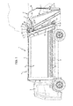
Figure 1 shows, in lateral elevation, a first preferred embodiment of the refuse collection vehicle according to the present invention; -
Figure 2 is a three quarters rear perspective view of part of the vehicle ofFigure 1 ; -
Figures 3 to 5 show, in an enlarged scale, a detail ofFigure 1 in respective operating configurations; and -
Figures 6 to 8 correspond, respectively, toFigures 3, 4 and5 and show a portion of a second preferred embodiment of the vehicle according to the present invention. - In
Figure 1 , number 1 indicates, as a whole, a vehicle for the collection and compaction of refuse and comprising aperipheral frame 2 mounted on wheels, acab 3 and body 4 mounted on theperipheral frame 2. The body 4 is designed to contain the refuse, has a generally parallelepiped shape and comprises a floor, aroof 5, a front transverse wall facing thecab 3 and twolongitudinal sides walls 6. - At its rear end, the body 4 terminates with a
peripheral frame 7, which is rigidly connected to, or integral with, the body 4 and defines arear opening 8 closed by atailgate 9 coupled to theperipheral frame 7 to rotate between a normal lowered position, in which thetailgate 9 is in abutment against theperipheral frame 7 and closes the rear opening 8 (Figures 1 and2 ), and a raised position (shown inFigure 1 with dashed lines and inFigure 5 ), in which thetailgate 9 is rotated upwards to leave free therear opening 8 allowing the emptying of the body 4. - In particular, the
peripheral frame 7 comprises a lower cross member (not visible in the attached figures) integral with a free edge of the floor, twolateral uprights 10 integral with the respective free edges of theside walls 6, and anupper cross member 11 integral with a free edge of theroof 5 and substantially horizontal and coplanar to theroof 5 itself. The lower cross member and thelateral uprights 10 are limited, on the side facing thetailgate 9, by respective flat surfaces, coplanar with each other and defining, in their totality, aU-shaped abutment 12, which is covered by agasket 13 and cooperates, when thetailgate 9 is arranged in the lowered position, with thetailgate 9 itself to close in a sealed way therear opening 8. Preferably, thegasket 13 extends along the lower cross member and along the whole, or at least a large part of the, length of theuprights 10. - As shown in
Figure 2 , thetailgate 9 is defined by a box-shaped body comprising twolateral walls 14, atop wall 15 substantially coplanar with theroof 5 of the body 4 when thetailgate 9 is in its lowered position, and a bottom wall, which faces thetop wall 15 and defines, together with thelateral walls 14 and with theupper wall 15 itself, aloading hopper 16 for the refuse. - For this purpose, the
tailgate 9 houses acompaction device 17 comprising an articulated mono-blade (of known type), which is mounted along guides formed on thelateral walls 14 and is movable, in use, to push the refuse loaded into thehopper 16 within the body 4 and compact them against a backpressure and expulsion plate (known and not shown) mounted to slide along the body 4. - At its rear end, the
tailgate 9 supports a containers lifting-turning device 18 (of known type) adapted to hook, lift and turn the refuse bins (not shown) to empty them into thehopper 16. - When arranged in its lowered position (
Figures 1-3 ), thetailgate 9 is made integral with the body 4 by a locking means 19 comprising twohooks 20, each of which is rigidly connected to a lower end of a respective upright 10, protrudes towards thetailgate 9 and is U-shaped with its concavity facing upwards so as to be able to be engaged, in use, from top to bottom, by arespective pin 21 carried by a correspondinglateral wall 14 of thetailgate 9. - The
tailgate 9 comprises, finally, twostruts 22 having the function of fixing thetailgate 9 in an intermediate opening position during maintenance operations; eachstrut 22 is hinged to a respectivelateral wall 14 above therespective pin 21 and, in a normal resting position, is fixed to thelateral wall 14 itself. - To rotate the
tailgate 9 from the lowered closed position to the raised open position, the vehicle 1 comprises an actuation means defined by twoactuation groups 23, which are arranged on opposite sides of thetailgate 9 in a position facing the respectivelateral walls 14 to a level below that of theupper wall 15 and, when thetailgate 9 is arranged in its lowered closed position, of the roof 5 (Figure 2 ). - The two
actuation groups 23 are identical and therefore, for purposes of clarity, only one of them will be described, in particular theactuation group 23 shown inFigures 1 ,3 ,4 and5 . - As shown in
Figure 3 , each upright 10 carries integrally connected, at one of its upper ends, i.e. approximately at theupper cross member 11, abracket 24 parallel to theside walls 6 and projecting backwards with respect to therespective uprights 10; and theactuation group 23 taken into consideration comprises alever 25, which is hinged, at a first end, on therespective bracket 24 to rotate, with respect to thebracket 24 itself, about anaxis 26 which is common to anotheractuation group 23, is fixed with respect to the body 4 and is horizontal and transverse to theuprights 10 and to theside walls 14. Theactuation group 23 comprises, in addition, anactuation member 27, which is constituted by a fluid-pressure operated cylinder, in this case an oil-hydraulic cylinder, having abody 28 hinged to the free end of thelever 25 to rotate with respect to thelever 25 about anaxis 29 parallel to theaxis 26, and anoutlet sliding member 30, a free end thereof being hinged to thebracket 24 to rotate about anaxis 31 parallel to theaxes axis 26. Theactuation member 27 is configured and mounted so that the displacement of theoutlet sliding element 30 towards an extracted position (Figure 5 ) determines a rotation of thelever 25 upwards (counterclockwise inFigures 1 ,3 ,4 and5 ) about theaxis 26. - The
tailgate 9 has at an upper level, corresponding toactuation group 23, anappendix 32 projecting upwards, which is hinged to an intermediate point of thelever 25 to rotate, with respect to thelever 25 itself, about anaxis 33 parallel to theaxes axes lever 25. - The
lever 25 is provided with alateral shoulder 34 adapted to cooperate with a frontlateral edge 35 of theappendix 32 to define, with theappendix 32 itself, a stop means 36 to limit the rotation of thetailgate 9 about theaxis 33 at a determined angle A that, in the example shown, is comprised between 10° and 25° preferably about 15°, but which is, in any case such as to determine a displacement upwards of theaxis 33 sufficient to disengage thepins 21 from therespective hooks 20. - The operation of the
tailgate 9 will now be described starting from the configuration shown inFigure 3 , in which thetailgate 9 is in its lowered closed position, and thelateral edge 35 of theappendix 32 forms, with theshoulder 34, the angle A. - The activation of the
actuation members 27 determines the extraction of theoutlet sliding element 30 with consequent upwards rotation of thelevers 25 about theaxis 26. During a first part of this rotation, theappendix 32 and, therefore, thetailgate 9 are free to rotate about theaxis 33 in the direction opposite to that of thelevers 25. Ultimately, to this first part of the rotation of thelevers 25 corresponds a simple sliding upwards of thetailgate 9 in its lowered closed position in abutment on theperipheral frame 7 and the disengagement of thepins 21 from thehooks 20. - This first part of rotation ends when the
lateral edges 35 are received in contact with therespective shoulders 34 making thetailgate 9 and thelevers 25 integral with each other for the purposes of the subsequent rotation about theaxis 26. During the closing of thetailgate 9, all the movements described above are performed in reverse sequence. - In connection with the above, it should be highlighted the fact that the configuration of the
actuation groups 23 is such as to allow bothactuation members 27 to operate "in thrust" or extension during the lifting of thetailgate 9 with consequent possibility of reducing the size of theactuation members 27 themselves, and to arrange theactuation groups 23 at a level lower than that of theroof 5 by reducing, in this way, the vertical dimensions of the vehicle 1. - The embodiment of
Figures 6 to 8 differs from the embodiment described above substantially only for the use of a different stop means 36. In this case, in fact, theappendix 32 has, at its upper end, arear extension 37 which protrudes towards theaxis 31 and carries apin 38 parallel to theaxes slot 39 formed through an intermediate portion of thelever 25 and transverse to thelever 25 itself. - When the
tailgate 9 and thelevers 25 are arranged in their lowered positions (Figure 6 ) thepins 38 are in contact with an upper end ofrespective slots 39; accordingly, a first rotation, of amplitude A, of thelevers 25 determines the simple sliding of thepins 38 along therespective slots 39 with consequent rotation of thetailgate 9 about theaxis 33 with respect to thelevers 25, the lifting of thetailgate 9 upwards and the disengagement of thepins 21 from theirrespective hooks 20. At the end of this first rotation, thepins 38 are received in contact with the lower end of therespective slots 39 with the result that a further upwards rotation of thelevers 25 causes the simultaneous rotation of thetailgate 9 and of thelevers 25 about theaxis 26. - In conclusion, it should be specified that the above relatively to the actuation means of the
tailgate 9 remains valid also in the case where the vehicle 1 is not of back-loading type as in the example described, but of front or lateral loading type. In these cases, thetailgate 9 does not have the function of the refuse loading hopper and, consequently, is devoid of thecompaction device 17 and the containers lifting-turning device 18.
Claims (9)
- Refuse collection vehicle comprising a body (4) which is designed to contain the refuse and has a rear opening (8) provided with a peripheral frame (7), which has a upper cross portion (11) arranged at a determined level, two uprights (10) and a lower cross portion; a tailgate (9) closing the rear opening (8), the tailgate (9) being rotatably connected to an upper end of the peripheral frame (7); and actuation means (23) to move the tailgate (9) between a raised open position and a lowered closed position, in which the tailgate (9) abuts against the peripheral frame (7); and the vehicle (1) being characterized in that the actuation means (23) comprise two actuation groups (23) arranged on opposite sides of the tailgate (9), approximately at said upper cross portion (11); each actuation group (23) comprising a lever (25) having a first end hinged to the body (4) to rotate about a first horizontal axis (26) which is fixed with respect to the body (4), and an actuation member (27), which is arranged under the lever (25) and is interposed between the body (4) and a second end of the lever (25) to rotate the lever (25), with respect to the body (4), about the first axis (26); and the tailgate (9) being hinged to the lever (25) to rotate, with respect to the lever (25), about a second axis (33), which is parallel to the first axis (26), is interposed between the first and second ends of lever (25) and is movable with the lever (25).
- The vehicle claimed in Claim 1, wherein the actuation means (23) are arranged mainly under said level.
- The vehicle claimed in Claim 1 or 2, wherein each actuation member (27) comprises a fluid-pressure operated cylinder (27) having an outlet member (30) movable from a retracted position to an extracted position to move the tailgate (9) from the lowered closed position to the raised open position.
- The vehicle claimed in Claim 3, wherein the fluid-pressure operated cylinder (27) comprises a body (28) hinged to the second end of the lever (25) to rotate, with respect to the lever (25), about a third axis (29) parallel to the first axis (26), the outlet member (30) having a free end hinged to the body (4) to rotate about a fourth axis (31) parallel to the third axis (29) and arranged at a level lower than that of the first axis (26).
- The vehicle claimed in anyone of the preceding Claims, wherein stop means (36) are provided on the actuation means (23) to limit a free rotation of the tailgate (9) with respect to the lever (25) and about the second axis (33) to a determined angle (A), and to cause the tailgate (9) to move a determined length substantially in contact with the peripheral frame (7) when performing said free rotation.
- The vehicle claimed in Claim 5, wherein the stop means (36) comprise at least a lateral shoulder (34) provided on a respective said lever (25) between the first (26) and the second axis (33) to cooperate frontally with a lateral edge (35) of the tailgate (9) to limit the rotation of the tailgate (9) about the second axis (33) to said determined angle (A).
- The vehicle claimed in Claim 6, wherein said determined angle (A) is between 10° and 25°.
- The vehicle claimed in Claim 5, wherein the stop means (36) comprises at least a slot (38) provided on, and extending transversely to, a respective lever (25), and at least a pin (39) carried by the tailgate (9), parallel to the first axis (26) and engaging, in a transversely sliding manner, the slot (38) to limit the rotation of the tailgate (9) about the second axis (33) to said determined angle (A).
- The vehicle claimed in Claim 5 or 8, and comprising locking means (19) to clamp the tailgate (9) to the peripheral frame (7) when the tailgate (9) is in the lowered closed position; the locking means (19) comprising hook means (20) provided on the peripheral frame (7) and pin means (21) provided on the tailgate (9); the hook means (20) comprising at least a U-shaped hook (20) arranged with its concavity facing upwards and having a depth lower than said determined length.
Applications Claiming Priority (1)
| Application Number | Priority Date | Filing Date | Title |
|---|---|---|---|
| IT000945A ITTO20110945A1 (en) | 2011-10-19 | 2011-10-19 | VEHICLE FOR WASTE COLLECTION |
Publications (2)
| Publication Number | Publication Date |
|---|---|
| EP2583915A1 true EP2583915A1 (en) | 2013-04-24 |
| EP2583915B1 EP2583915B1 (en) | 2015-09-09 |
Family
ID=44993791
Family Applications (1)
| Application Number | Title | Priority Date | Filing Date |
|---|---|---|---|
| EP12189340.8A Not-in-force EP2583915B1 (en) | 2011-10-19 | 2012-10-19 | Refuse collection vehicle |
Country Status (2)
| Country | Link |
|---|---|
| EP (1) | EP2583915B1 (en) |
| IT (1) | ITTO20110945A1 (en) |
Cited By (1)
| Publication number | Priority date | Publication date | Assignee | Title |
|---|---|---|---|---|
| DE102023126730A1 (en) * | 2023-09-29 | 2025-04-03 | Zoeller Tech Sp z.o.o. | lifting arm |
Citations (3)
| Publication number | Priority date | Publication date | Assignee | Title |
|---|---|---|---|---|
| FR2174736A1 (en) * | 1972-03-09 | 1973-10-19 | Sita | |
| US4307541A (en) * | 1979-11-30 | 1981-12-29 | Dempster Systems Inc. | Tail-gate operating and locking mechanism |
| US5498067A (en) * | 1994-01-14 | 1996-03-12 | Mcneilus Truck And Manufacturing, Inc. | Lifting latch hinge for tailgate on refuse hauler/compactor |
-
2011
- 2011-10-19 IT IT000945A patent/ITTO20110945A1/en unknown
-
2012
- 2012-10-19 EP EP12189340.8A patent/EP2583915B1/en not_active Not-in-force
Patent Citations (3)
| Publication number | Priority date | Publication date | Assignee | Title |
|---|---|---|---|---|
| FR2174736A1 (en) * | 1972-03-09 | 1973-10-19 | Sita | |
| US4307541A (en) * | 1979-11-30 | 1981-12-29 | Dempster Systems Inc. | Tail-gate operating and locking mechanism |
| US5498067A (en) * | 1994-01-14 | 1996-03-12 | Mcneilus Truck And Manufacturing, Inc. | Lifting latch hinge for tailgate on refuse hauler/compactor |
Cited By (3)
| Publication number | Priority date | Publication date | Assignee | Title |
|---|---|---|---|---|
| DE102023126730A1 (en) * | 2023-09-29 | 2025-04-03 | Zoeller Tech Sp z.o.o. | lifting arm |
| EP4545447A1 (en) * | 2023-09-29 | 2025-04-30 | Zoeller Tech Sp. z.o.o. | LIFTING ARM FOR A REFUSE COLLECTION VEHICLE |
| DE102023126730B4 (en) * | 2023-09-29 | 2025-05-28 | Zoeller Tech Sp z.o.o. | lifting arm |
Also Published As
| Publication number | Publication date |
|---|---|
| EP2583915B1 (en) | 2015-09-09 |
| ITTO20110945A1 (en) | 2013-04-20 |
Similar Documents
| Publication | Publication Date | Title |
|---|---|---|
| US3696951A (en) | Refuse collection vehicles | |
| US4877366A (en) | Refuse vehicle | |
| US3921839A (en) | Packing and ejecting means for a refuse truck | |
| US3687317A (en) | Lid lock for front end loader container | |
| US4260316A (en) | Refuse collection vehicle | |
| CN108501967B (en) | Underframe assembly, car body and hopper car | |
| US20190009983A1 (en) | Shield for three compartment rear load packer | |
| US3232463A (en) | Refuse collection and packer body | |
| US2748964A (en) | Refuse truck packer loader | |
| EP2583915B1 (en) | Refuse collection vehicle | |
| DK2886492T3 (en) | The collection container to a garbage truck | |
| US7997852B1 (en) | Side loader garbage truck | |
| CN109319358A (en) | Integral type No leakage back-loading type waste compacting vehicle | |
| CN101495360B (en) | mechanical tailgate | |
| GB2188302A (en) | Container emptying mechanisms | |
| CN108791334B (en) | Bulk cargo transportation hopper car | |
| KR200193653Y1 (en) | Carrying box lifting and dump apparatus of trailer for cultivator | |
| EP1385695B1 (en) | Container for compacting paper waste | |
| CN220181740U (en) | Rear door of arm-pulling box, rear door control system and arm-pulling box | |
| US3779409A (en) | Container dumping mechanism for a rear loader refuse vehicle | |
| KR100962518B1 (en) | Apparatus for removing residue on loading deck of vehicle | |
| CN108556856B (en) | Bottom door opening and closing mechanism, car body and hopper car | |
| CN112339319A (en) | Garbage compressor | |
| CN214083024U (en) | Garbage compressor | |
| CN101508260B (en) | Three-direction tipping vehicle self-discharging door opening device |
Legal Events
| Date | Code | Title | Description |
|---|---|---|---|
| PUAI | Public reference made under article 153(3) epc to a published international application that has entered the european phase |
Free format text: ORIGINAL CODE: 0009012 |
|
| AK | Designated contracting states |
Kind code of ref document: A1 Designated state(s): AL AT BE BG CH CY CZ DE DK EE ES FI FR GB GR HR HU IE IS IT LI LT LU LV MC MK MT NL NO PL PT RO RS SE SI SK SM TR |
|
| AX | Request for extension of the european patent |
Extension state: BA ME |
|
| 17P | Request for examination filed |
Effective date: 20131023 |
|
| RBV | Designated contracting states (corrected) |
Designated state(s): AL AT BE BG CH CY CZ DE DK EE ES FI FR GB GR HR HU IE IS IT LI LT LU LV MC MK MT NL NO PL PT RO RS SE SI SK SM TR |
|
| GRAP | Despatch of communication of intention to grant a patent |
Free format text: ORIGINAL CODE: EPIDOSNIGR1 |
|
| RIC1 | Information provided on ipc code assigned before grant |
Ipc: B65F 3/00 20060101AFI20150312BHEP |
|
| INTG | Intention to grant announced |
Effective date: 20150326 |
|
| RIN1 | Information on inventor provided before grant (corrected) |
Inventor name: BASSO, FABRIZIO Inventor name: MORETTI, LOREDANA |
|
| GRAS | Grant fee paid |
Free format text: ORIGINAL CODE: EPIDOSNIGR3 |
|
| GRAA | (expected) grant |
Free format text: ORIGINAL CODE: 0009210 |
|
| AK | Designated contracting states |
Kind code of ref document: B1 Designated state(s): AL AT BE BG CH CY CZ DE DK EE ES FI FR GB GR HR HU IE IS IT LI LT LU LV MC MK MT NL NO PL PT RO RS SE SI SK SM TR |
|
| REG | Reference to a national code |
Ref country code: GB Ref legal event code: FG4D |
|
| REG | Reference to a national code |
Ref country code: AT Ref legal event code: REF Ref document number: 747946 Country of ref document: AT Kind code of ref document: T Effective date: 20150915 Ref country code: CH Ref legal event code: EP |
|
| REG | Reference to a national code |
Ref country code: IE Ref legal event code: FG4D |
|
| REG | Reference to a national code |
Ref country code: FR Ref legal event code: PLFP Year of fee payment: 4 |
|
| REG | Reference to a national code |
Ref country code: DE Ref legal event code: R096 Ref document number: 602012010276 Country of ref document: DE |
|
| REG | Reference to a national code |
Ref country code: NL Ref legal event code: MP Effective date: 20150909 |
|
| PG25 | Lapsed in a contracting state [announced via postgrant information from national office to epo] |
Ref country code: NO Free format text: LAPSE BECAUSE OF FAILURE TO SUBMIT A TRANSLATION OF THE DESCRIPTION OR TO PAY THE FEE WITHIN THE PRESCRIBED TIME-LIMIT Effective date: 20151209 Ref country code: GR Free format text: LAPSE BECAUSE OF FAILURE TO SUBMIT A TRANSLATION OF THE DESCRIPTION OR TO PAY THE FEE WITHIN THE PRESCRIBED TIME-LIMIT Effective date: 20151210 Ref country code: LT Free format text: LAPSE BECAUSE OF FAILURE TO SUBMIT A TRANSLATION OF THE DESCRIPTION OR TO PAY THE FEE WITHIN THE PRESCRIBED TIME-LIMIT Effective date: 20150909 Ref country code: FI Free format text: LAPSE BECAUSE OF FAILURE TO SUBMIT A TRANSLATION OF THE DESCRIPTION OR TO PAY THE FEE WITHIN THE PRESCRIBED TIME-LIMIT Effective date: 20150909 Ref country code: LV Free format text: LAPSE BECAUSE OF FAILURE TO SUBMIT A TRANSLATION OF THE DESCRIPTION OR TO PAY THE FEE WITHIN THE PRESCRIBED TIME-LIMIT Effective date: 20150909 |
|
| REG | Reference to a national code |
Ref country code: LT Ref legal event code: MG4D |
|
| REG | Reference to a national code |
Ref country code: AT Ref legal event code: MK05 Ref document number: 747946 Country of ref document: AT Kind code of ref document: T Effective date: 20150909 |
|
| PG25 | Lapsed in a contracting state [announced via postgrant information from national office to epo] |
Ref country code: SE Free format text: LAPSE BECAUSE OF FAILURE TO SUBMIT A TRANSLATION OF THE DESCRIPTION OR TO PAY THE FEE WITHIN THE PRESCRIBED TIME-LIMIT Effective date: 20150909 Ref country code: RS Free format text: LAPSE BECAUSE OF FAILURE TO SUBMIT A TRANSLATION OF THE DESCRIPTION OR TO PAY THE FEE WITHIN THE PRESCRIBED TIME-LIMIT Effective date: 20150909 Ref country code: ES Free format text: LAPSE BECAUSE OF FAILURE TO SUBMIT A TRANSLATION OF THE DESCRIPTION OR TO PAY THE FEE WITHIN THE PRESCRIBED TIME-LIMIT Effective date: 20150909 Ref country code: HR Free format text: LAPSE BECAUSE OF FAILURE TO SUBMIT A TRANSLATION OF THE DESCRIPTION OR TO PAY THE FEE WITHIN THE PRESCRIBED TIME-LIMIT Effective date: 20150909 |
|
| PG25 | Lapsed in a contracting state [announced via postgrant information from national office to epo] |
Ref country code: NL Free format text: LAPSE BECAUSE OF FAILURE TO SUBMIT A TRANSLATION OF THE DESCRIPTION OR TO PAY THE FEE WITHIN THE PRESCRIBED TIME-LIMIT Effective date: 20150909 |
|
| PG25 | Lapsed in a contracting state [announced via postgrant information from national office to epo] |
Ref country code: IT Free format text: LAPSE BECAUSE OF FAILURE TO SUBMIT A TRANSLATION OF THE DESCRIPTION OR TO PAY THE FEE WITHIN THE PRESCRIBED TIME-LIMIT Effective date: 20150909 Ref country code: IS Free format text: LAPSE BECAUSE OF FAILURE TO SUBMIT A TRANSLATION OF THE DESCRIPTION OR TO PAY THE FEE WITHIN THE PRESCRIBED TIME-LIMIT Effective date: 20160109 Ref country code: EE Free format text: LAPSE BECAUSE OF FAILURE TO SUBMIT A TRANSLATION OF THE DESCRIPTION OR TO PAY THE FEE WITHIN THE PRESCRIBED TIME-LIMIT Effective date: 20150909 Ref country code: SK Free format text: LAPSE BECAUSE OF FAILURE TO SUBMIT A TRANSLATION OF THE DESCRIPTION OR TO PAY THE FEE WITHIN THE PRESCRIBED TIME-LIMIT Effective date: 20150909 Ref country code: CZ Free format text: LAPSE BECAUSE OF FAILURE TO SUBMIT A TRANSLATION OF THE DESCRIPTION OR TO PAY THE FEE WITHIN THE PRESCRIBED TIME-LIMIT Effective date: 20150909 |
|
| PG25 | Lapsed in a contracting state [announced via postgrant information from national office to epo] |
Ref country code: RO Free format text: LAPSE BECAUSE OF FAILURE TO SUBMIT A TRANSLATION OF THE DESCRIPTION OR TO PAY THE FEE WITHIN THE PRESCRIBED TIME-LIMIT Effective date: 20150909 Ref country code: PT Free format text: LAPSE BECAUSE OF FAILURE TO SUBMIT A TRANSLATION OF THE DESCRIPTION OR TO PAY THE FEE WITHIN THE PRESCRIBED TIME-LIMIT Effective date: 20160111 Ref country code: AT Free format text: LAPSE BECAUSE OF FAILURE TO SUBMIT A TRANSLATION OF THE DESCRIPTION OR TO PAY THE FEE WITHIN THE PRESCRIBED TIME-LIMIT Effective date: 20150909 Ref country code: PL Free format text: LAPSE BECAUSE OF FAILURE TO SUBMIT A TRANSLATION OF THE DESCRIPTION OR TO PAY THE FEE WITHIN THE PRESCRIBED TIME-LIMIT Effective date: 20150909 |
|
| REG | Reference to a national code |
Ref country code: CH Ref legal event code: PL |
|
| REG | Reference to a national code |
Ref country code: DE Ref legal event code: R097 Ref document number: 602012010276 Country of ref document: DE |
|
| PG25 | Lapsed in a contracting state [announced via postgrant information from national office to epo] |
Ref country code: MC Free format text: LAPSE BECAUSE OF FAILURE TO SUBMIT A TRANSLATION OF THE DESCRIPTION OR TO PAY THE FEE WITHIN THE PRESCRIBED TIME-LIMIT Effective date: 20150909 |
|
| PLBE | No opposition filed within time limit |
Free format text: ORIGINAL CODE: 0009261 |
|
| STAA | Information on the status of an ep patent application or granted ep patent |
Free format text: STATUS: NO OPPOSITION FILED WITHIN TIME LIMIT |
|
| REG | Reference to a national code |
Ref country code: IE Ref legal event code: MM4A |
|
| PG25 | Lapsed in a contracting state [announced via postgrant information from national office to epo] |
Ref country code: LI Free format text: LAPSE BECAUSE OF NON-PAYMENT OF DUE FEES Effective date: 20151031 Ref country code: CH Free format text: LAPSE BECAUSE OF NON-PAYMENT OF DUE FEES Effective date: 20151031 |
|
| 26N | No opposition filed |
Effective date: 20160610 |
|
| PG25 | Lapsed in a contracting state [announced via postgrant information from national office to epo] |
Ref country code: DK Free format text: LAPSE BECAUSE OF FAILURE TO SUBMIT A TRANSLATION OF THE DESCRIPTION OR TO PAY THE FEE WITHIN THE PRESCRIBED TIME-LIMIT Effective date: 20150909 Ref country code: SI Free format text: LAPSE BECAUSE OF FAILURE TO SUBMIT A TRANSLATION OF THE DESCRIPTION OR TO PAY THE FEE WITHIN THE PRESCRIBED TIME-LIMIT Effective date: 20150909 |
|
| REG | Reference to a national code |
Ref country code: FR Ref legal event code: PLFP Year of fee payment: 5 |
|
| PG25 | Lapsed in a contracting state [announced via postgrant information from national office to epo] |
Ref country code: IE Free format text: LAPSE BECAUSE OF NON-PAYMENT OF DUE FEES Effective date: 20151019 |
|
| PGFP | Annual fee paid to national office [announced via postgrant information from national office to epo] |
Ref country code: FR Payment date: 20160928 Year of fee payment: 5 |
|
| PG25 | Lapsed in a contracting state [announced via postgrant information from national office to epo] |
Ref country code: BE Free format text: LAPSE BECAUSE OF FAILURE TO SUBMIT A TRANSLATION OF THE DESCRIPTION OR TO PAY THE FEE WITHIN THE PRESCRIBED TIME-LIMIT Effective date: 20150909 |
|
| PGFP | Annual fee paid to national office [announced via postgrant information from national office to epo] |
Ref country code: GB Payment date: 20161019 Year of fee payment: 5 Ref country code: DE Payment date: 20161011 Year of fee payment: 5 |
|
| PG25 | Lapsed in a contracting state [announced via postgrant information from national office to epo] |
Ref country code: BG Free format text: LAPSE BECAUSE OF FAILURE TO SUBMIT A TRANSLATION OF THE DESCRIPTION OR TO PAY THE FEE WITHIN THE PRESCRIBED TIME-LIMIT Effective date: 20150909 Ref country code: SM Free format text: LAPSE BECAUSE OF FAILURE TO SUBMIT A TRANSLATION OF THE DESCRIPTION OR TO PAY THE FEE WITHIN THE PRESCRIBED TIME-LIMIT Effective date: 20150909 Ref country code: HU Free format text: LAPSE BECAUSE OF FAILURE TO SUBMIT A TRANSLATION OF THE DESCRIPTION OR TO PAY THE FEE WITHIN THE PRESCRIBED TIME-LIMIT; INVALID AB INITIO Effective date: 20121019 |
|
| PG25 | Lapsed in a contracting state [announced via postgrant information from national office to epo] |
Ref country code: CY Free format text: LAPSE BECAUSE OF FAILURE TO SUBMIT A TRANSLATION OF THE DESCRIPTION OR TO PAY THE FEE WITHIN THE PRESCRIBED TIME-LIMIT Effective date: 20150909 |
|
| PG25 | Lapsed in a contracting state [announced via postgrant information from national office to epo] |
Ref country code: MT Free format text: LAPSE BECAUSE OF FAILURE TO SUBMIT A TRANSLATION OF THE DESCRIPTION OR TO PAY THE FEE WITHIN THE PRESCRIBED TIME-LIMIT Effective date: 20150909 |
|
| PG25 | Lapsed in a contracting state [announced via postgrant information from national office to epo] |
Ref country code: LU Free format text: LAPSE BECAUSE OF NON-PAYMENT OF DUE FEES Effective date: 20151019 |
|
| REG | Reference to a national code |
Ref country code: DE Ref legal event code: R119 Ref document number: 602012010276 Country of ref document: DE |
|
| GBPC | Gb: european patent ceased through non-payment of renewal fee |
Effective date: 20171019 |
|
| PG25 | Lapsed in a contracting state [announced via postgrant information from national office to epo] |
Ref country code: MK Free format text: LAPSE BECAUSE OF FAILURE TO SUBMIT A TRANSLATION OF THE DESCRIPTION OR TO PAY THE FEE WITHIN THE PRESCRIBED TIME-LIMIT Effective date: 20150909 Ref country code: TR Free format text: LAPSE BECAUSE OF FAILURE TO SUBMIT A TRANSLATION OF THE DESCRIPTION OR TO PAY THE FEE WITHIN THE PRESCRIBED TIME-LIMIT Effective date: 20150909 |
|
| REG | Reference to a national code |
Ref country code: FR Ref legal event code: ST Effective date: 20180629 |
|
| PG25 | Lapsed in a contracting state [announced via postgrant information from national office to epo] |
Ref country code: DE Free format text: LAPSE BECAUSE OF NON-PAYMENT OF DUE FEES Effective date: 20180501 Ref country code: GB Free format text: LAPSE BECAUSE OF NON-PAYMENT OF DUE FEES Effective date: 20171019 |
|
| PG25 | Lapsed in a contracting state [announced via postgrant information from national office to epo] |
Ref country code: FR Free format text: LAPSE BECAUSE OF NON-PAYMENT OF DUE FEES Effective date: 20171031 |
|
| PG25 | Lapsed in a contracting state [announced via postgrant information from national office to epo] |
Ref country code: AL Free format text: LAPSE BECAUSE OF FAILURE TO SUBMIT A TRANSLATION OF THE DESCRIPTION OR TO PAY THE FEE WITHIN THE PRESCRIBED TIME-LIMIT Effective date: 20150909 |