EP2583836A1 - A method for assembling a wheel hub bearing unit - Google Patents
A method for assembling a wheel hub bearing unit Download PDFInfo
- Publication number
- EP2583836A1 EP2583836A1 EP20120188048 EP12188048A EP2583836A1 EP 2583836 A1 EP2583836 A1 EP 2583836A1 EP 20120188048 EP20120188048 EP 20120188048 EP 12188048 A EP12188048 A EP 12188048A EP 2583836 A1 EP2583836 A1 EP 2583836A1
- Authority
- EP
- European Patent Office
- Prior art keywords
- inner ring
- wheel hub
- bearing unit
- hub bearing
- ring
- Prior art date
- Legal status (The legal status is an assumption and is not a legal conclusion. Google has not performed a legal analysis and makes no representation as to the accuracy of the status listed.)
- Granted
Links
Images

Classifications
-
- F—MECHANICAL ENGINEERING; LIGHTING; HEATING; WEAPONS; BLASTING
- F16—ENGINEERING ELEMENTS AND UNITS; GENERAL MEASURES FOR PRODUCING AND MAINTAINING EFFECTIVE FUNCTIONING OF MACHINES OR INSTALLATIONS; THERMAL INSULATION IN GENERAL
- F16C—SHAFTS; FLEXIBLE SHAFTS; ELEMENTS OR CRANKSHAFT MECHANISMS; ROTARY BODIES OTHER THAN GEARING ELEMENTS; BEARINGS
- F16C19/00—Bearings with rolling contact, for exclusively rotary movement
- F16C19/02—Bearings with rolling contact, for exclusively rotary movement with bearing balls essentially of the same size in one or more circular rows
- F16C19/14—Bearings with rolling contact, for exclusively rotary movement with bearing balls essentially of the same size in one or more circular rows for both radial and axial load
- F16C19/18—Bearings with rolling contact, for exclusively rotary movement with bearing balls essentially of the same size in one or more circular rows for both radial and axial load with two or more rows of balls
- F16C19/181—Bearings with rolling contact, for exclusively rotary movement with bearing balls essentially of the same size in one or more circular rows for both radial and axial load with two or more rows of balls with angular contact
- F16C19/183—Bearings with rolling contact, for exclusively rotary movement with bearing balls essentially of the same size in one or more circular rows for both radial and axial load with two or more rows of balls with angular contact with two rows at opposite angles
- F16C19/184—Bearings with rolling contact, for exclusively rotary movement with bearing balls essentially of the same size in one or more circular rows for both radial and axial load with two or more rows of balls with angular contact with two rows at opposite angles in O-arrangement
- F16C19/186—Bearings with rolling contact, for exclusively rotary movement with bearing balls essentially of the same size in one or more circular rows for both radial and axial load with two or more rows of balls with angular contact with two rows at opposite angles in O-arrangement with three raceways provided integrally on parts other than race rings, e.g. third generation hubs
-
- B—PERFORMING OPERATIONS; TRANSPORTING
- B60—VEHICLES IN GENERAL
- B60B—VEHICLE WHEELS; CASTORS; AXLES FOR WHEELS OR CASTORS; INCREASING WHEEL ADHESION
- B60B27/00—Hubs
- B60B27/0005—Hubs with ball bearings
-
- B—PERFORMING OPERATIONS; TRANSPORTING
- B60—VEHICLES IN GENERAL
- B60B—VEHICLE WHEELS; CASTORS; AXLES FOR WHEELS OR CASTORS; INCREASING WHEEL ADHESION
- B60B27/00—Hubs
- B60B27/0078—Hubs characterised by the fixation of bearings
-
- B—PERFORMING OPERATIONS; TRANSPORTING
- B60—VEHICLES IN GENERAL
- B60B—VEHICLE WHEELS; CASTORS; AXLES FOR WHEELS OR CASTORS; INCREASING WHEEL ADHESION
- B60B27/00—Hubs
- B60B27/0094—Hubs one or more of the bearing races are formed by the hub
-
- F—MECHANICAL ENGINEERING; LIGHTING; HEATING; WEAPONS; BLASTING
- F16—ENGINEERING ELEMENTS AND UNITS; GENERAL MEASURES FOR PRODUCING AND MAINTAINING EFFECTIVE FUNCTIONING OF MACHINES OR INSTALLATIONS; THERMAL INSULATION IN GENERAL
- F16C—SHAFTS; FLEXIBLE SHAFTS; ELEMENTS OR CRANKSHAFT MECHANISMS; ROTARY BODIES OTHER THAN GEARING ELEMENTS; BEARINGS
- F16C25/00—Bearings for exclusively rotary movement adjustable for wear or play
- F16C25/06—Ball or roller bearings
-
- F—MECHANICAL ENGINEERING; LIGHTING; HEATING; WEAPONS; BLASTING
- F16—ENGINEERING ELEMENTS AND UNITS; GENERAL MEASURES FOR PRODUCING AND MAINTAINING EFFECTIVE FUNCTIONING OF MACHINES OR INSTALLATIONS; THERMAL INSULATION IN GENERAL
- F16C—SHAFTS; FLEXIBLE SHAFTS; ELEMENTS OR CRANKSHAFT MECHANISMS; ROTARY BODIES OTHER THAN GEARING ELEMENTS; BEARINGS
- F16C43/00—Assembling bearings
- F16C43/04—Assembling rolling-contact bearings
-
- B—PERFORMING OPERATIONS; TRANSPORTING
- B60—VEHICLES IN GENERAL
- B60B—VEHICLE WHEELS; CASTORS; AXLES FOR WHEELS OR CASTORS; INCREASING WHEEL ADHESION
- B60B2380/00—Bearings
- B60B2380/10—Type
- B60B2380/12—Ball bearings
-
- B—PERFORMING OPERATIONS; TRANSPORTING
- B60—VEHICLES IN GENERAL
- B60B—VEHICLE WHEELS; CASTORS; AXLES FOR WHEELS OR CASTORS; INCREASING WHEEL ADHESION
- B60B2380/00—Bearings
- B60B2380/70—Arrangements
- B60B2380/73—Double track
-
- B—PERFORMING OPERATIONS; TRANSPORTING
- B60—VEHICLES IN GENERAL
- B60B—VEHICLE WHEELS; CASTORS; AXLES FOR WHEELS OR CASTORS; INCREASING WHEEL ADHESION
- B60B27/00—Hubs
-
- B—PERFORMING OPERATIONS; TRANSPORTING
- B60—VEHICLES IN GENERAL
- B60B—VEHICLE WHEELS; CASTORS; AXLES FOR WHEELS OR CASTORS; INCREASING WHEEL ADHESION
- B60B2900/00—Purpose of invention
- B60B2900/10—Reduction of
- B60B2900/111—Weight
-
- B—PERFORMING OPERATIONS; TRANSPORTING
- B60—VEHICLES IN GENERAL
- B60B—VEHICLE WHEELS; CASTORS; AXLES FOR WHEELS OR CASTORS; INCREASING WHEEL ADHESION
- B60B2900/00—Purpose of invention
- B60B2900/10—Reduction of
- B60B2900/112—Costs
-
- B—PERFORMING OPERATIONS; TRANSPORTING
- B60—VEHICLES IN GENERAL
- B60B—VEHICLE WHEELS; CASTORS; AXLES FOR WHEELS OR CASTORS; INCREASING WHEEL ADHESION
- B60B2900/00—Purpose of invention
- B60B2900/10—Reduction of
- B60B2900/114—Size
-
- F—MECHANICAL ENGINEERING; LIGHTING; HEATING; WEAPONS; BLASTING
- F16—ENGINEERING ELEMENTS AND UNITS; GENERAL MEASURES FOR PRODUCING AND MAINTAINING EFFECTIVE FUNCTIONING OF MACHINES OR INSTALLATIONS; THERMAL INSULATION IN GENERAL
- F16C—SHAFTS; FLEXIBLE SHAFTS; ELEMENTS OR CRANKSHAFT MECHANISMS; ROTARY BODIES OTHER THAN GEARING ELEMENTS; BEARINGS
- F16C2226/00—Joining parts; Fastening; Assembling or mounting parts
- F16C2226/50—Positive connections
- F16C2226/60—Positive connections with threaded parts, e.g. bolt and nut connections
-
- F—MECHANICAL ENGINEERING; LIGHTING; HEATING; WEAPONS; BLASTING
- F16—ENGINEERING ELEMENTS AND UNITS; GENERAL MEASURES FOR PRODUCING AND MAINTAINING EFFECTIVE FUNCTIONING OF MACHINES OR INSTALLATIONS; THERMAL INSULATION IN GENERAL
- F16C—SHAFTS; FLEXIBLE SHAFTS; ELEMENTS OR CRANKSHAFT MECHANISMS; ROTARY BODIES OTHER THAN GEARING ELEMENTS; BEARINGS
- F16C2229/00—Setting preload
-
- F—MECHANICAL ENGINEERING; LIGHTING; HEATING; WEAPONS; BLASTING
- F16—ENGINEERING ELEMENTS AND UNITS; GENERAL MEASURES FOR PRODUCING AND MAINTAINING EFFECTIVE FUNCTIONING OF MACHINES OR INSTALLATIONS; THERMAL INSULATION IN GENERAL
- F16C—SHAFTS; FLEXIBLE SHAFTS; ELEMENTS OR CRANKSHAFT MECHANISMS; ROTARY BODIES OTHER THAN GEARING ELEMENTS; BEARINGS
- F16C2326/00—Articles relating to transporting
- F16C2326/01—Parts of vehicles in general
- F16C2326/02—Wheel hubs or castors
Definitions
- the present invention relates to a method of assembling a wheel hub bearing unit.
- the wheel hub bearing units of known design are provided with an axis of rotation and comprise:
- the inner ring is mounted on a tubular extension of the cylindrical body and abuts against a shoulder of the flanged ring so as to leave an axially protruding end portion of the tubular extension beyond an annular outer surface of the inner ring.
- the axial locking member is made by cold roll forming the end portion against the outer annular surface of the inner ring.
- the rolled edge although having proved to be very reliable as an axial locking member, does not only determine an increase of the axial dimensions of the entire wheel hub bearing unit, but also leads to an increase in the overall weight of the wheel hub bearing unit. Moreover, despite the technological progress made in cold rolling, the correct determination of the axial preload on the two rows of balls has always proved to be a rather critical operation to be performed with great caution, often at the expense of the manufacturing speed of the wheel hub bearing unit.
- the present invention proposes an assembling method as defined in claim 1.
- a wheel hub-bearing unit having the features set forth in the appended claims.
- numeral 1 designates as a whole a wheel hub bearing unit.
- the unit 1 is provided with an axis A of rotation and comprises:
- the cylindrical body 23 extends along axis A from the flange 21 and through the outer ring 10, and is provided with a shoulder 24,
- the shoulder 24 is identified, on the side of the row C1, by a cylindrical surface 25 having an inner diameter substantially equal to a diameter of the bottom of the raceway 22.
- the shoulder 24 is defined by an annular front surface 26 and a cylindrical surface 27 having a diameter which is less than the diameter of the cylindrical surface 25.
- the surface 27 externally delimits a tubular extension 28 of the cylindrical body 23.
- the unit 1 comprises an inner ring 30 which is mounted on the tubular extension 28 of the flanged ring 20 and provides a respective raceway 31 for the row C2.
- the outboard row C1 is received between the raceways 11 and 22, while the row C2 is received between the raceways 12 and 31, and the mutual position of raceways 11 and 22 and the raceways 12 and 31 is such that the rings 10, 20 and 30 together with the rows C1 and C2 are configured as a double row, angular contact ball bearing.
- the unit 1 finally comprises an axial locking device 500, which locks the inner ring 30 with respect to flanged ring 20 and comprises, in the embodiment illustrated in Figure 1 , a helical ridge 51 made on a cylindrical inner surface 32 of ring 30 and an inner helical groove 52 made or formed in the surface 27.
- the cylindrical surface 27 is initially smooth.
- the groove 52 has a shape complementary to a shape of the helical ridge 51 and is formed during the assembly of the inner ring 30.
- the latter is a heat-treated ring and has a hardness of magnitude greater than a hardness of the material constituting at least the tubular extension 28.
- the progressive engagement of the ridge 51 in the groove 52 i.e. the progressive carving of the groove 52 by the ridge 51 during the coupling of ring 30 on the tubular portion 28, allows to locate the inner ring 30 in a locking position against the relative row C2 so as to exert a preload force on the two rows C1 and C2 proportional to a tightening torque applied to the inner ring 30 while screwing it onto the flanged ring 20.
- the helical ridge 51 and the helical groove 52 have each a respective end 51a, 52a situated on the side closer to the first raceway 22; once the tightening of inner ring 30 is completed, the ends 51a and 52a coincide.
- the inner ring 30 In its locking position, the inner ring 30 defines with the surface 26 of the shoulder 24, a gap M of given axial length which is set so as to prevent axial contact between the inner ring 30 and the flanged ring 20. In this way, it will suffice to set the tightening torque of the inner ring 30 on the flanged ring 20 so as to set the preloading force on the two rows C1 and C2 with absolute accuracy.
- the inner ring 30 comprises two (or more) diametrically opposite flat portions (or flats) 60 formed on an outer cylindrical surface 37 of the inner ring 30, or provides two or more axial blind holes 60' made through an axially inner annular surface 33 of the same inner ring 30.
- the flat portions 60 do not extend over the entire axial extent of the surface 37, and, similarly as the axial blind holes 60', they provide passive maneuvering elements for maneuvering the inner ring 30 on the flanged ring 20 so as to cause the helical ridge 51 to progressively engage the helical groove 52 until the inner ring 30 reaches the relative row C2 of bearing balls.
- the cylindrical inner surface 32 of the ring 30 is an inner single-diameter surface and covers the entire axial length of the ring 30, extending from the annular surface 33 to an annular, axially outer surface 34 of the same inner ring 30 facing the shoulder 24. Therefore, the helical ridge 51 extends along the entire axial length of the inner ring 30 ensuring a high contact surface with the groove 52 and a very reduced, if not practically nil, possibility that the inner ring 30 may come off the flanged ring 20.
- the embodiment illustrated in Figure 2 relates to a device 501 similar to device 500, by which the device 501 differs in that the cylindrical inner surface 32 of the ring 30 has an internal surface with a double diameter, and comprises a smooth centering portion 35 and an engagement portion 36 providing the helical ridge 51.
- cylindrical outer surface 27 is a double diameter surface and comprises a respective smooth centering portion 28 predominantly located on the body 23, and a respective engagement portion 29 providing the helical groove 52 and located on the tubular extension 28.
- the centering portion 35 is arranged axially outwardly of the engagement portion 36 and radially inwardly of the raceway 31.
- the centering portion 35 has a diameter and an axial length both being larger than the diameter and the axial length, respectively, of the locking portion 36.
- the different sizes in diameter between the centering portion 35 and the locking portion 36, as well as between the centering portion 28 and the engagement portion 29, allow to make an annular step 39 on the inner ring 30 and an annular step 79 on the body 23, wherein the annular step 79 as a radial height which is shorter than the radial height of shoulder 24.
- the relative centering portion 35 is arranged in direct contact with the centering portion 28 of the flanged ring 20, thereby ensuring a correct positioning of the inner ring 30 with respect to the flanged ring 20 and also with respect to the axis A, while the corresponding engagement portion 36 will be engaged with the engagement portion 29 of the flanged ring 20 in order to lock the inner ring 30 inside the flanged ring 20.
- the two steps 39 and 79 are located axially facing one another and not in contact with each other, as well as the surface 34 and the surface 26 which will continue to define therebetween a gap M of crucial importance in setting the preload.
- the step 39 does not only allow a rapid machining of the portion 36, but also prevents the raceway 31 from being affected either by any deformation induced in the ring 30 due to the machining steps for forming the ridge 51 in the portion 36, and also by any deformation and stress which the ring 30 is subjected to during the assembly of the unit 1.
- the step 39 gives the advantage of isolating the raceway 31 from the stress that is generated.
- the engagement portion 36 in which the helical ridge 51 is formed is the thickest portion of the inner ring 30, and therefore is the least deformable portion, and the farthest from the raceway 31. Therefore, the stress induced in raceway 31 is reduced to a minimum or negligible level, both during the machining step of forming the ridge 51, and during the step of assembling the inner ring 30 on the flanged ring 20.
- the axial length of the portion 36 does cover the whole axial length of the inner ring 30, as previously described and shown for the embodiment of Figure 1 , the mutual axial locking between the inner ring 30 and the flanged ring 20 is always guaranteed by the fact that the inner ring 30 is forced on the flanged ring 20, i.e. on the tubular portion 28, obtaining progressively the groove 52.
- the embodiment illustrated in Figure 3 relates to a device 502 similar to the device 501, from which the device 502 differs due to the fact that, in the inner ring 30, the centering portion 35 is located axially inwardly of the locking portion 36 and has a diameter smaller than the diameter of the locking portion 36. Furthermore, in the device 502, the centering portion 35 has an axial length larger than an axial length of the locking portion 36, and extends in either axial direction beyond the axial position of the raceway 31 on the inner ring 30. This arrangement provides an extremely accurate concentricity between the inner ring 30 and the flanged ring 20.
- the raceway 31 is arranged in a position axially intermediate between the surface 33 and the annular step 39, i.e. on the radially thicker part of the inner ring 30 rather than on the radially thinner part, making unit 1 in its different variants extremely versatile.
- the presence of the step 39 substantially prevents the raceway 31 from being affected by any deformation induced in the ring 30 due to the machining of the ridge 51.
- the substantial correspondence of the axial positions of the raceway 31 and the centering portion 35 of the ring 30 allows the inner raceway 31 to transfer Hertzian stresses caused by the movement of the rolling elements around the axis A to a cylinder-on-cylinder type of contact, which is homogeneous.
- the embodiment shown in Figure 4 relates to a device 503 similar to device 502, from which the device 503 differs in that it comprises, furthermore, an annular protuberance 54, which axially delimits the engagement portion 36 on the side opposite side to the step 39, and is axially bounded by the surface 34.
- the protuberance 54 has a radial end 55, preferably but not necessarily rounded, which is positioned in contact with portion 29 and seals the helical ridge 51 with respect to the gap M in such a way that, while the inner ring 30 is being assembled, any chips deriving from the formation of the groove 52 cannot be disseminated within the rings 10 and 20 and between the raceways 22 and 31, but remain enclosed between the protuberance 54 and the shoulder 39.
- the protuberance 54 has an axial thickness larger than an average axial dimension of the helical ridge 51 so as to confer also a certain rigidity and strength to the engagement portion 36.
- the annular protuberance 54 has an inner diameter such as to generate a slight radial interference with the cylindrical surface 27 on which the helical groove 52 is formed.
- the unit 1 bearing wheel hub in the variants described above also allows to significantly simplify the entire manufacturing process of the unit 1.
- the exclusion of such a step does not only involve a speeding up of the manufacturing of the unit 1, but also allows to eliminate the steps of measuring the components in order to allow, precisely, a correct coupling.
Landscapes
- Engineering & Computer Science (AREA)
- Mechanical Engineering (AREA)
- General Engineering & Computer Science (AREA)
- Rolling Contact Bearings (AREA)
- Support Of The Bearing (AREA)
Description
- The present invention relates to a method of assembling a wheel hub bearing unit.
- In general, the wheel hub bearing units of known design are provided with an axis of rotation and comprise:
- a dual row of rolling elements arranged side by side along the axis of rotation;
- an outer ring with two raceways for the two rows of rolling elements;
- a flanged ring comprising an attachment flange for a wheel of a vehicle and a cylindrical body which is integral with the flange and provides, on an outer surface, a raceway for a relative row of rolling elements;
- an inner ring mounted on the flanged ring on the opposite side of the flange and provided with a respective raceway for a relative row of rolling elements, and
- an axial locking member for locking the inner ring with respect to the flanged ring.
- In most applications of the wheel hub bearing unit described above and used in the automotive industry, the inner ring is mounted on a tubular extension of the cylindrical body and abuts against a shoulder of the flanged ring so as to leave an axially protruding end portion of the tubular extension beyond an annular outer surface of the inner ring. With these applications, the axial locking member is made by cold roll forming the end portion against the outer annular surface of the inner ring.
- The rolled edge, although having proved to be very reliable as an axial locking member, does not only determine an increase of the axial dimensions of the entire wheel hub bearing unit, but also leads to an increase in the overall weight of the wheel hub bearing unit. Moreover, despite the technological progress made in cold rolling, the correct determination of the axial preload on the two rows of balls has always proved to be a rather critical operation to be performed with great caution, often at the expense of the manufacturing speed of the wheel hub bearing unit.
- Finally, in the automotive industry, especially as a result of new standards in terms of CO2 emissions, there is an ever increasing need for components being lighter and less bulky.
- It is therefore an object of the present invention to provide a wheel hub bearing unit, which, without having to renounce to the capability of locking of the inner ring of known units, permits not only a reduction in terms of axial dimensions and weight, but also an easier application of the axial preload on the unit.
- According to a first aspect, the present invention proposes an assembling method as defined in
claim 1. According to a further aspect of the invention, there is provided a wheel hub-bearing unit having the features set forth in the appended claims. - The invention will now be described with reference to the accompanying drawings, showing some exemplary, non-limiting embodiments, in which:
-
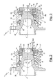
Figure 1 is a cross-sectional view in a longitudinal plane of a first preferred embodiment of a wheel hub bearing unit according to the present invention; -
Figure 2 is a cross-sectional view in a longitudinal plane of a second preferred embodiment of a wheel hub bearing unit; -
Figure 3 is a sectional view of a longitudinal plane of a third preferred embodiment of a wheel hub bearing unit; -
Figure 4 is a sectional view of a longitudinal plane, with parts removed for clarity and on an enlarged scale, of a preferred embodiment of a detail of the wheel hub bearing unit ofFigure 3 . - With reference to
Figure 1 ,numeral 1 designates as a whole a wheel hub bearing unit. Theunit 1 is provided with an axis A of rotation and comprises: - two rows C1 and C2 of rolling elements, preferably but not necessarily bearing balls, axially arranged side by side along the axis A;
- an
outer ring 10 provided with tworaceways - a
flanged ring 20, which is provided with aflange 21 transversal to the axis A, for supporting a vehicle wheel (not shown) and acylindrical body 23 integral with theflange 21 and externally provided with araceway 22 for the row C1. - Since the
flange 21 identifies the so-called "outboard side" ofunit 1, and the row C1 is arranged close to theflange 21, the row C1 is usually called "outboard row" of theunit 1, while, consequently, the row C2 is called "inboard row" of theunit 1. Similarly, unless otherwise specified in the ensuing description, terms such as "inboard" and "outboard" will be used with the same meaning have explained herein above. - The
cylindrical body 23 extends along axis A from theflange 21 and through theouter ring 10, and is provided with ashoulder 24, Theshoulder 24 is identified, on the side of the row C1, by acylindrical surface 25 having an inner diameter substantially equal to a diameter of the bottom of theraceway 22. On the side of the row C2, theshoulder 24 is defined by anannular front surface 26 and acylindrical surface 27 having a diameter which is less than the diameter of thecylindrical surface 25. In the embodiment illustrated inFigure 1 , thesurface 27 externally delimits atubular extension 28 of thecylindrical body 23. - Furthermore, the
unit 1 comprises aninner ring 30 which is mounted on thetubular extension 28 of theflanged ring 20 and provides arespective raceway 31 for the row C2. In other words: the outboard row C1 is received between theraceways raceways raceways raceways rings - Setting the preload in a double row, angular contact ball bearing of the above described type is done by bringing
flanged ring 20 and theinner ring 30 axially close to one another while locking theinner ring 30 on theflanged ring 20, so as to compress the bearing balls of rows C1 and C2 within the respective pairs ofraceways - The
unit 1 finally comprises anaxial locking device 500, which locks theinner ring 30 with respect to flangedring 20 and comprises, in the embodiment illustrated inFigure 1 , ahelical ridge 51 made on a cylindricalinner surface 32 ofring 30 and an innerhelical groove 52 made or formed in thesurface 27. In a preferred embodiment, thecylindrical surface 27 is initially smooth. Thegroove 52 has a shape complementary to a shape of thehelical ridge 51 and is formed during the assembly of theinner ring 30. In fact, the latter is a heat-treated ring and has a hardness of magnitude greater than a hardness of the material constituting at least thetubular extension 28. - The progressive engagement of the
ridge 51 in thegroove 52, i.e. the progressive carving of thegroove 52 by theridge 51 during the coupling ofring 30 on thetubular portion 28, allows to locate theinner ring 30 in a locking position against the relative row C2 so as to exert a preload force on the two rows C1 and C2 proportional to a tightening torque applied to theinner ring 30 while screwing it onto theflanged ring 20. Thehelical ridge 51 and thehelical groove 52 have each arespective end first raceway 22; once the tightening ofinner ring 30 is completed, theends - In its locking position, the
inner ring 30 defines with thesurface 26 of theshoulder 24, a gap M of given axial length which is set so as to prevent axial contact between theinner ring 30 and theflanged ring 20. In this way, it will suffice to set the tightening torque of theinner ring 30 on theflanged ring 20 so as to set the preloading force on the two rows C1 and C2 with absolute accuracy. To this end, theinner ring 30 comprises two (or more) diametrically opposite flat portions (or flats) 60 formed on an outercylindrical surface 37 of theinner ring 30, or provides two or more axial blind holes 60' made through an axially innerannular surface 33 of the sameinner ring 30. Theflat portions 60 do not extend over the entire axial extent of thesurface 37, and, similarly as the axial blind holes 60', they provide passive maneuvering elements for maneuvering theinner ring 30 on theflanged ring 20 so as to cause thehelical ridge 51 to progressively engage thehelical groove 52 until theinner ring 30 reaches the relative row C2 of bearing balls. - In the embodiment illustrated in
Figure 1 , the cylindricalinner surface 32 of thering 30 is an inner single-diameter surface and covers the entire axial length of thering 30, extending from theannular surface 33 to an annular, axiallyouter surface 34 of the sameinner ring 30 facing theshoulder 24. Therefore, thehelical ridge 51 extends along the entire axial length of theinner ring 30 ensuring a high contact surface with thegroove 52 and a very reduced, if not practically nil, possibility that theinner ring 30 may come off theflanged ring 20. - The embodiment illustrated in
Figure 2 relates to adevice 501 similar todevice 500, by which thedevice 501 differs in that the cylindricalinner surface 32 of thering 30 has an internal surface with a double diameter, and comprises asmooth centering portion 35 and anengagement portion 36 providing thehelical ridge 51. - Also the cylindrical
outer surface 27 is a double diameter surface and comprises a respectivesmooth centering portion 28 predominantly located on thebody 23, and arespective engagement portion 29 providing thehelical groove 52 and located on thetubular extension 28. - In the
device 501, the centeringportion 35 is arranged axially outwardly of theengagement portion 36 and radially inwardly of theraceway 31. The centeringportion 35 has a diameter and an axial length both being larger than the diameter and the axial length, respectively, of thelocking portion 36. - The different sizes in diameter between the centering
portion 35 and thelocking portion 36, as well as between the centeringportion 28 and theengagement portion 29, allow to make anannular step 39 on theinner ring 30 and anannular step 79 on thebody 23, wherein theannular step 79 as a radial height which is shorter than the radial height ofshoulder 24. - With the
inner ring 30 in its locked position, therelative centering portion 35 is arranged in direct contact with the centeringportion 28 of theflanged ring 20, thereby ensuring a correct positioning of theinner ring 30 with respect to theflanged ring 20 and also with respect to the axis A, while thecorresponding engagement portion 36 will be engaged with theengagement portion 29 of theflanged ring 20 in order to lock theinner ring 30 inside theflanged ring 20. In this locking position, the twosteps surface 34 and thesurface 26 which will continue to define therebetween a gap M of crucial importance in setting the preload. - In fact, once the centering
portion 35 is fitted on the centeringportion 28, thereby providing for an initial centering of theinner ring 30 on thebody 23, progressive engagement of theengagement portion 36 with theengagement portion 29 causes, firstly, theraceway 31 to come in contact initially with the row C2, then brings theinner ring 30 to be fully centered on thebody 23, and finally allows a progressive preloading to be applied to theunit 1, depending on the torque applied to thering 30. - Moreover, the
step 39 does not only allow a rapid machining of theportion 36, but also prevents theraceway 31 from being affected either by any deformation induced in thering 30 due to the machining steps for forming theridge 51 in theportion 36, and also by any deformation and stress which thering 30 is subjected to during the assembly of theunit 1. In fact, in order to form thegroove 52, it is necessary to plastically deform the material of thebody 23 and, therefore, the stress being imparted reaches rather high values: thestep 39 gives the advantage of isolating theraceway 31 from the stress that is generated. Furthermore, it will be appreciated that in the embodiment ofFigure 2 , theengagement portion 36 in which thehelical ridge 51 is formed is the thickest portion of theinner ring 30, and therefore is the least deformable portion, and the farthest from theraceway 31. Therefore, the stress induced inraceway 31 is reduced to a minimum or negligible level, both during the machining step of forming theridge 51, and during the step of assembling theinner ring 30 on theflanged ring 20. - Although the axial length of the
portion 36 does cover the whole axial length of theinner ring 30, as previously described and shown for the embodiment ofFigure 1 , the mutual axial locking between theinner ring 30 and theflanged ring 20 is always guaranteed by the fact that theinner ring 30 is forced on theflanged ring 20, i.e. on thetubular portion 28, obtaining progressively thegroove 52. - The embodiment illustrated in
Figure 3 relates to adevice 502 similar to thedevice 501, from which thedevice 502 differs due to the fact that, in theinner ring 30, thecentering portion 35 is located axially inwardly of thelocking portion 36 and has a diameter smaller than the diameter of thelocking portion 36. Furthermore, in thedevice 502, the centeringportion 35 has an axial length larger than an axial length of thelocking portion 36, and extends in either axial direction beyond the axial position of theraceway 31 on theinner ring 30. This arrangement provides an extremely accurate concentricity between theinner ring 30 and theflanged ring 20. - Differently from the
device 501, where theraceway 31 is located in an axially intermediate position between thesurface 34 and theannular step 39, in thedevice 502 theraceway 31 is arranged in a position axially intermediate between thesurface 33 and theannular step 39, i.e. on the radially thicker part of theinner ring 30 rather than on the radially thinner part, makingunit 1 in its different variants extremely versatile. - Even in the case of the
device 502, the presence of thestep 39 substantially prevents theraceway 31 from being affected by any deformation induced in thering 30 due to the machining of theridge 51. At the same time, the substantial correspondence of the axial positions of theraceway 31 and the centeringportion 35 of thering 30 allows theinner raceway 31 to transfer Hertzian stresses caused by the movement of the rolling elements around the axis A to a cylinder-on-cylinder type of contact, which is homogeneous. - The embodiment shown in
Figure 4 relates to adevice 503 similar todevice 502, from which thedevice 503 differs in that it comprises, furthermore, an annular protuberance 54, which axially delimits theengagement portion 36 on the side opposite side to thestep 39, and is axially bounded by thesurface 34. The protuberance 54 has a radial end 55, preferably but not necessarily rounded, which is positioned in contact withportion 29 and seals thehelical ridge 51 with respect to the gap M in such a way that, while theinner ring 30 is being assembled, any chips deriving from the formation of thegroove 52 cannot be disseminated within therings raceways shoulder 39. - The protuberance 54 has an axial thickness larger than an average axial dimension of the
helical ridge 51 so as to confer also a certain rigidity and strength to theengagement portion 36. Preferably, the annular protuberance 54 has an inner diameter such as to generate a slight radial interference with thecylindrical surface 27 on which thehelical groove 52 is formed. - The
unit 1 bearing wheel hub in the variants described above also allows to significantly simplify the entire manufacturing process of theunit 1. As stated herein above, since it is possible to set preloading values by acting directly onunit 1, it is no longer necessary to provide a coupling step of the components (outer ring with inner rings and rolling elements) of theunit 1 as done heretofore. The exclusion of such a step does not only involve a speeding up of the manufacturing of theunit 1, but also allows to eliminate the steps of measuring the components in order to allow, precisely, a correct coupling. - It is understood that the invention is not limited to the embodiments described and illustrated herein, which are to be considered as examples of implementing a wheel hub bearing unit. These embodiments are susceptible of further modifications regarding shapes and arrangement of parts, constructional and assembly details.
Claims (11)
- A method for assembling a wheel hub bearing unit (1) the, the method comprising the steps of:- providing two rows (C1, C2) of rolling elements;- providing an outer ring (10) forming two raceways (11, 12) for the two rows (C1, C2) of rolling bodies;- providing a first inner ring (20) forming a first internal raceway (22) for a first one (C1) of the two rows (C1, C2) of rolling bodies and a cylindrical outer surface (27);- providing a second inner ring (30) forming a second raceway (31) for a second one (C2) of the two rows (C1, C2) of rolling elements, an inner cylindrical surface (32), and a helical ridge (51) formed in the inner cylindrical surface (32);- arranging the two rows of rolling elements (C1, C2) between the raceways (11, 12) of the outer ring (10) and (22) of the first inner ring (20);- rotating and advancing the second ring (30) around and along the outer cylindrical surface (27) of the first inner ring (20), in such a way that:the helical ridge (51) progressively carves a helical groove (52) in the cylindrical outer surface (27), andthe second inner ring (30) reaches a locking position against the second row (C2) of rolling bodies so as to exert a preload force on the two rows (C1, C2) proportional to a tightening torque applied to the second inner ring (30) to lock it on the first inner ring (20).
- The method of claim 1, wherein the cylindrical outer surface (27) of the first inner ring (20) is initially smooth.
- A wheel hub bearing unit assembled according to the method of claim 1 or 2, wherein the second inner ring (30) in its locking position defines with an axial shoulder (24) of the first inner ring (20), a gap (M) of predetermined axial length preventing axial contact between the first inner ring (20) and the second inner ring (30).
- A wheel hub bearing unit according to claim 3, wherein the second inner ring (30) includes maneuvering means (60, 60'), formed either or on a cylindrical outer surface (35) or an annular axially inner surface (33) of the same second inner ring (30), for maneuvering the second inner ring (30) so as to make it rotate and advance to carve progressively the helical groove (52).
- A wheel hub bearing unit according to claim 3 or 4, wherein the inner surface (32) is a cylindrical, single-diameter surface extending along an entire axial length of the second inner ring (30).
- A wheel hub bearing unit according to claim 3 or 4, wherein the inner surface (32) is a double diameter cylindrical surface comprising a first centering portion (35) and a first engagement portion (36) providing the helical ridge (51).
- A wheel hub bearing unit according to claim 6, wherein the cylindrical outer surface (27) is a double diameter surface and comprises a second centering portion (28) of a shape complementary to a shape of the first centering portion (35), and a second engagement portion (29) providing the helical groove (52); the first and the second centering portions (35, 28) abutting each other in radial contact for centering the second inner ring (30) with respect to the first inner ring (20).
- A wheel hub bearing unit according to claim 6 or 7, wherein the first centering portion (35) is arranged between the shoulder (24) and the first engagement portion (36), and has a diameter larger than a diameter of the first engagement portion (36).
- A wheel hub bearing unit according to claim 6 or 7, wherein the first centering portion (35) is arranged on the opposite side of the first engagement portion (36) with respect to the shoulder (24) and has a diameter smaller than a diameter of the first engagement portion (36).
- A wheel hub bearing unit according to claim 8, further comprising a sealing annular element (54), which axially delimits the first engagement portion (36) and is arranged in contact with the second engagement portion (29) for sealing of the helical ridge (51) with respect to the inside of the wheel hub bearing unit (1).
- A wheel hub bearing unit according to any one of claims 3 to 10, wherein the helical ridge (51) and the helical groove (52) each have a respective end (51a, 52a) located on a side closer to the first raceway (22), said ends being coincident.
Applications Claiming Priority (1)
| Application Number | Priority Date | Filing Date | Title |
|---|---|---|---|
| IT000949A ITTO20110949A1 (en) | 2011-10-19 | 2011-10-19 | HUB-WHEEL BEARING UNIT |
Publications (2)
| Publication Number | Publication Date |
|---|---|
| EP2583836A1 true EP2583836A1 (en) | 2013-04-24 |
| EP2583836B1 EP2583836B1 (en) | 2014-07-16 |
Family
ID=44993792
Family Applications (1)
| Application Number | Title | Priority Date | Filing Date |
|---|---|---|---|
| EP20120188048 Not-in-force EP2583836B1 (en) | 2011-10-19 | 2012-10-10 | A method for assembling a wheel hub bearing unit |
Country Status (2)
| Country | Link |
|---|---|
| EP (1) | EP2583836B1 (en) |
| IT (1) | ITTO20110949A1 (en) |
Cited By (3)
| Publication number | Priority date | Publication date | Assignee | Title |
|---|---|---|---|---|
| DE102018207144A1 (en) * | 2018-05-08 | 2019-11-14 | Zf Friedrichshafen Ag | Gear arrangement and method for producing a gear arrangement |
| CN112483543A (en) * | 2019-09-11 | 2021-03-12 | 斯凯孚公司 | Method for mounting a sensor bearing unit and unit suitable for the method |
| JP2023037318A (en) * | 2021-09-03 | 2023-03-15 | Ntn株式会社 | Wheel bearing device |
Citations (3)
| Publication number | Priority date | Publication date | Assignee | Title |
|---|---|---|---|---|
| JPH09196605A (en) * | 1996-01-18 | 1997-07-31 | Toyota Motor Corp | Measuring method and assembling method of double-row angular contact ball bearing |
| WO2007145005A1 (en) * | 2006-06-14 | 2007-12-21 | Ntn Corporation | Bearing unit for driving wheel |
| EP1978270A1 (en) * | 2006-01-20 | 2008-10-08 | JTEKT Corporation | Method for manufacturing hub unit and hub unit |
-
2011
- 2011-10-19 IT IT000949A patent/ITTO20110949A1/en unknown
-
2012
- 2012-10-10 EP EP20120188048 patent/EP2583836B1/en not_active Not-in-force
Patent Citations (3)
| Publication number | Priority date | Publication date | Assignee | Title |
|---|---|---|---|---|
| JPH09196605A (en) * | 1996-01-18 | 1997-07-31 | Toyota Motor Corp | Measuring method and assembling method of double-row angular contact ball bearing |
| EP1978270A1 (en) * | 2006-01-20 | 2008-10-08 | JTEKT Corporation | Method for manufacturing hub unit and hub unit |
| WO2007145005A1 (en) * | 2006-06-14 | 2007-12-21 | Ntn Corporation | Bearing unit for driving wheel |
Cited By (4)
| Publication number | Priority date | Publication date | Assignee | Title |
|---|---|---|---|---|
| DE102018207144A1 (en) * | 2018-05-08 | 2019-11-14 | Zf Friedrichshafen Ag | Gear arrangement and method for producing a gear arrangement |
| CN112483543A (en) * | 2019-09-11 | 2021-03-12 | 斯凯孚公司 | Method for mounting a sensor bearing unit and unit suitable for the method |
| US12092163B2 (en) | 2019-09-11 | 2024-09-17 | Aktiebolaget Skf | Method for mounting a sensor bearing unit, and sensor bearing unit adapted to such a method |
| JP2023037318A (en) * | 2021-09-03 | 2023-03-15 | Ntn株式会社 | Wheel bearing device |
Also Published As
| Publication number | Publication date |
|---|---|
| ITTO20110949A1 (en) | 2013-04-20 |
| EP2583836B1 (en) | 2014-07-16 |
Similar Documents
| Publication | Publication Date | Title |
|---|---|---|
| US6796714B2 (en) | Rolling-bearing unit for wheel support | |
| US9505266B2 (en) | Wheel bearing apparatus and axle module | |
| KR101195279B1 (en) | Hub unit, rolling bearing device, producing method for rolling bearing device, and assembling device and assembling method for rolling bearing device | |
| US5782565A (en) | Ball bearing for an automobile wheel hub | |
| CN103826869B (en) | Wheel bearings and bearing devices | |
| US10493712B2 (en) | Method for manufacturing a pulley device, a pulley device according to such a manufacturing method and an engine fitted with such a pulley | |
| US6672769B2 (en) | Bearing apparatus and producing method thereof | |
| US8997601B2 (en) | Steering column comprising a steering bearing, and a steering bearing of a steering column | |
| JP6009149B2 (en) | Manufacturing method of wheel bearing device | |
| US9393836B2 (en) | Bearing for wheel, and bearing device for wheel | |
| ITTO960175A1 (en) | METHOD OF ASSEMBLING THE BEARING OF A HUB FOR A VEHICLE WHEEL ON THE RELEVANT POST AND BEARING-POST SYSTEM SO | |
| EP3054184B1 (en) | Double-row tapered roller bearing unit and method of manufacturing the bearing unit | |
| EP2583836B1 (en) | A method for assembling a wheel hub bearing unit | |
| EP2839899B1 (en) | Wheel bearing device and manufacturing method therefor | |
| WO2018092673A1 (en) | Method for splining wheel bearing | |
| US20130283940A1 (en) | Wear compensation device for a gear set and associated mounting method | |
| JP4425652B2 (en) | Wheel bearing device and manufacturing method thereof | |
| WO2008007474A1 (en) | Bearing device for wheel | |
| US20080273824A1 (en) | Bearing device for axle and fixing structure using the same | |
| US20070160317A1 (en) | Wheel bearing in a wheel carrier | |
| EP1624205B1 (en) | Bearing apparatus for a wheel of vehicle | |
| US20070177836A1 (en) | Outer ring of a wheel bearing | |
| US20130108201A1 (en) | Wheel bearing device | |
| US20070217727A1 (en) | Wheel hub and bearing arrangement, and a method for mounting such an arrangement | |
| WO2013015334A1 (en) | Wheel bearing assembly device and assembly method therefor |
Legal Events
| Date | Code | Title | Description |
|---|---|---|---|
| PUAI | Public reference made under article 153(3) epc to a published international application that has entered the european phase |
Free format text: ORIGINAL CODE: 0009012 |
|
| AK | Designated contracting states |
Kind code of ref document: A1 Designated state(s): AL AT BE BG CH CY CZ DE DK EE ES FI FR GB GR HR HU IE IS IT LI LT LU LV MC MK MT NL NO PL PT RO RS SE SI SK SM TR |
|
| AX | Request for extension of the european patent |
Extension state: BA ME |
|
| 17P | Request for examination filed |
Effective date: 20130916 |
|
| RBV | Designated contracting states (corrected) |
Designated state(s): AL AT BE BG CH CY CZ DE DK EE ES FI FR GB GR HR HU IE IS IT LI LT LU LV MC MK MT NL NO PL PT RO RS SE SI SK SM TR |
|
| RIC1 | Information provided on ipc code assigned before grant |
Ipc: F16C 25/06 20060101ALI20131212BHEP Ipc: B60B 27/00 20060101AFI20131212BHEP Ipc: F16C 19/18 20060101ALI20131212BHEP Ipc: F16C 23/06 20060101ALI20131212BHEP |
|
| GRAP | Despatch of communication of intention to grant a patent |
Free format text: ORIGINAL CODE: EPIDOSNIGR1 |
|
| INTG | Intention to grant announced |
Effective date: 20140130 |
|
| GRAS | Grant fee paid |
Free format text: ORIGINAL CODE: EPIDOSNIGR3 |
|
| GRAA | (expected) grant |
Free format text: ORIGINAL CODE: 0009210 |
|
| AK | Designated contracting states |
Kind code of ref document: B1 Designated state(s): AL AT BE BG CH CY CZ DE DK EE ES FI FR GB GR HR HU IE IS IT LI LT LU LV MC MK MT NL NO PL PT RO RS SE SI SK SM TR |
|
| REG | Reference to a national code |
Ref country code: GB Ref legal event code: FG4D |
|
| REG | Reference to a national code |
Ref country code: CH Ref legal event code: EP |
|
| REG | Reference to a national code |
Ref country code: IE Ref legal event code: FG4D |
|
| REG | Reference to a national code |
Ref country code: AT Ref legal event code: REF Ref document number: 677369 Country of ref document: AT Kind code of ref document: T Effective date: 20140815 |
|
| REG | Reference to a national code |
Ref country code: DE Ref legal event code: R096 Ref document number: 602012002438 Country of ref document: DE Effective date: 20140828 |
|
| REG | Reference to a national code |
Ref country code: SE Ref legal event code: TRGR |
|
| REG | Reference to a national code |
Ref country code: NL Ref legal event code: VDEP Effective date: 20140716 |
|
| REG | Reference to a national code |
Ref country code: AT Ref legal event code: MK05 Ref document number: 677369 Country of ref document: AT Kind code of ref document: T Effective date: 20140716 |
|
| REG | Reference to a national code |
Ref country code: LT Ref legal event code: MG4D |
|
| PG25 | Lapsed in a contracting state [announced via postgrant information from national office to epo] |
Ref country code: FI Free format text: LAPSE BECAUSE OF FAILURE TO SUBMIT A TRANSLATION OF THE DESCRIPTION OR TO PAY THE FEE WITHIN THE PRESCRIBED TIME-LIMIT Effective date: 20140716 Ref country code: ES Free format text: LAPSE BECAUSE OF FAILURE TO SUBMIT A TRANSLATION OF THE DESCRIPTION OR TO PAY THE FEE WITHIN THE PRESCRIBED TIME-LIMIT Effective date: 20140716 Ref country code: GR Free format text: LAPSE BECAUSE OF FAILURE TO SUBMIT A TRANSLATION OF THE DESCRIPTION OR TO PAY THE FEE WITHIN THE PRESCRIBED TIME-LIMIT Effective date: 20141017 Ref country code: PT Free format text: LAPSE BECAUSE OF FAILURE TO SUBMIT A TRANSLATION OF THE DESCRIPTION OR TO PAY THE FEE WITHIN THE PRESCRIBED TIME-LIMIT Effective date: 20141117 Ref country code: BG Free format text: LAPSE BECAUSE OF FAILURE TO SUBMIT A TRANSLATION OF THE DESCRIPTION OR TO PAY THE FEE WITHIN THE PRESCRIBED TIME-LIMIT Effective date: 20141016 Ref country code: LT Free format text: LAPSE BECAUSE OF FAILURE TO SUBMIT A TRANSLATION OF THE DESCRIPTION OR TO PAY THE FEE WITHIN THE PRESCRIBED TIME-LIMIT Effective date: 20140716 Ref country code: NO Free format text: LAPSE BECAUSE OF FAILURE TO SUBMIT A TRANSLATION OF THE DESCRIPTION OR TO PAY THE FEE WITHIN THE PRESCRIBED TIME-LIMIT Effective date: 20141016 |
|
| PG25 | Lapsed in a contracting state [announced via postgrant information from national office to epo] |
Ref country code: NL Free format text: LAPSE BECAUSE OF FAILURE TO SUBMIT A TRANSLATION OF THE DESCRIPTION OR TO PAY THE FEE WITHIN THE PRESCRIBED TIME-LIMIT Effective date: 20140716 Ref country code: PL Free format text: LAPSE BECAUSE OF FAILURE TO SUBMIT A TRANSLATION OF THE DESCRIPTION OR TO PAY THE FEE WITHIN THE PRESCRIBED TIME-LIMIT Effective date: 20140716 Ref country code: AT Free format text: LAPSE BECAUSE OF FAILURE TO SUBMIT A TRANSLATION OF THE DESCRIPTION OR TO PAY THE FEE WITHIN THE PRESCRIBED TIME-LIMIT Effective date: 20140716 Ref country code: IS Free format text: LAPSE BECAUSE OF FAILURE TO SUBMIT A TRANSLATION OF THE DESCRIPTION OR TO PAY THE FEE WITHIN THE PRESCRIBED TIME-LIMIT Effective date: 20141116 Ref country code: RS Free format text: LAPSE BECAUSE OF FAILURE TO SUBMIT A TRANSLATION OF THE DESCRIPTION OR TO PAY THE FEE WITHIN THE PRESCRIBED TIME-LIMIT Effective date: 20140716 Ref country code: CY Free format text: LAPSE BECAUSE OF FAILURE TO SUBMIT A TRANSLATION OF THE DESCRIPTION OR TO PAY THE FEE WITHIN THE PRESCRIBED TIME-LIMIT Effective date: 20140716 Ref country code: LV Free format text: LAPSE BECAUSE OF FAILURE TO SUBMIT A TRANSLATION OF THE DESCRIPTION OR TO PAY THE FEE WITHIN THE PRESCRIBED TIME-LIMIT Effective date: 20140716 |
|
| REG | Reference to a national code |
Ref country code: DE Ref legal event code: R097 Ref document number: 602012002438 Country of ref document: DE |
|
| PG25 | Lapsed in a contracting state [announced via postgrant information from national office to epo] |
Ref country code: CZ Free format text: LAPSE BECAUSE OF FAILURE TO SUBMIT A TRANSLATION OF THE DESCRIPTION OR TO PAY THE FEE WITHIN THE PRESCRIBED TIME-LIMIT Effective date: 20140716 Ref country code: EE Free format text: LAPSE BECAUSE OF FAILURE TO SUBMIT A TRANSLATION OF THE DESCRIPTION OR TO PAY THE FEE WITHIN THE PRESCRIBED TIME-LIMIT Effective date: 20140716 Ref country code: SK Free format text: LAPSE BECAUSE OF FAILURE TO SUBMIT A TRANSLATION OF THE DESCRIPTION OR TO PAY THE FEE WITHIN THE PRESCRIBED TIME-LIMIT Effective date: 20140716 Ref country code: DK Free format text: LAPSE BECAUSE OF FAILURE TO SUBMIT A TRANSLATION OF THE DESCRIPTION OR TO PAY THE FEE WITHIN THE PRESCRIBED TIME-LIMIT Effective date: 20140716 Ref country code: RO Free format text: LAPSE BECAUSE OF FAILURE TO SUBMIT A TRANSLATION OF THE DESCRIPTION OR TO PAY THE FEE WITHIN THE PRESCRIBED TIME-LIMIT Effective date: 20140716 |
|
| PLBE | No opposition filed within time limit |
Free format text: ORIGINAL CODE: 0009261 |
|
| STAA | Information on the status of an ep patent application or granted ep patent |
Free format text: STATUS: NO OPPOSITION FILED WITHIN TIME LIMIT |
|
| PG25 | Lapsed in a contracting state [announced via postgrant information from national office to epo] |
Ref country code: MC Free format text: LAPSE BECAUSE OF FAILURE TO SUBMIT A TRANSLATION OF THE DESCRIPTION OR TO PAY THE FEE WITHIN THE PRESCRIBED TIME-LIMIT Effective date: 20140716 Ref country code: LU Free format text: LAPSE BECAUSE OF FAILURE TO SUBMIT A TRANSLATION OF THE DESCRIPTION OR TO PAY THE FEE WITHIN THE PRESCRIBED TIME-LIMIT Effective date: 20141010 |
|
| 26N | No opposition filed |
Effective date: 20150417 |
|
| PG25 | Lapsed in a contracting state [announced via postgrant information from national office to epo] |
Ref country code: BE Free format text: LAPSE BECAUSE OF NON-PAYMENT OF DUE FEES Effective date: 20141031 |
|
| REG | Reference to a national code |
Ref country code: IE Ref legal event code: MM4A |
|
| PG25 | Lapsed in a contracting state [announced via postgrant information from national office to epo] |
Ref country code: IE Free format text: LAPSE BECAUSE OF NON-PAYMENT OF DUE FEES Effective date: 20141010 |
|
| REG | Reference to a national code |
Ref country code: FR Ref legal event code: PLFP Year of fee payment: 4 |
|
| PG25 | Lapsed in a contracting state [announced via postgrant information from national office to epo] |
Ref country code: SI Free format text: LAPSE BECAUSE OF FAILURE TO SUBMIT A TRANSLATION OF THE DESCRIPTION OR TO PAY THE FEE WITHIN THE PRESCRIBED TIME-LIMIT Effective date: 20140716 |
|
| REG | Reference to a national code |
Ref country code: CH Ref legal event code: PL |
|
| PG25 | Lapsed in a contracting state [announced via postgrant information from national office to epo] |
Ref country code: MT Free format text: LAPSE BECAUSE OF FAILURE TO SUBMIT A TRANSLATION OF THE DESCRIPTION OR TO PAY THE FEE WITHIN THE PRESCRIBED TIME-LIMIT Effective date: 20140716 Ref country code: HR Free format text: LAPSE BECAUSE OF FAILURE TO SUBMIT A TRANSLATION OF THE DESCRIPTION OR TO PAY THE FEE WITHIN THE PRESCRIBED TIME-LIMIT Effective date: 20140716 Ref country code: BE Free format text: LAPSE BECAUSE OF FAILURE TO SUBMIT A TRANSLATION OF THE DESCRIPTION OR TO PAY THE FEE WITHIN THE PRESCRIBED TIME-LIMIT Effective date: 20140716 Ref country code: HU Free format text: LAPSE BECAUSE OF FAILURE TO SUBMIT A TRANSLATION OF THE DESCRIPTION OR TO PAY THE FEE WITHIN THE PRESCRIBED TIME-LIMIT; INVALID AB INITIO Effective date: 20121010 Ref country code: TR Free format text: LAPSE BECAUSE OF FAILURE TO SUBMIT A TRANSLATION OF THE DESCRIPTION OR TO PAY THE FEE WITHIN THE PRESCRIBED TIME-LIMIT Effective date: 20140716 Ref country code: CH Free format text: LAPSE BECAUSE OF NON-PAYMENT OF DUE FEES Effective date: 20151031 Ref country code: LI Free format text: LAPSE BECAUSE OF NON-PAYMENT OF DUE FEES Effective date: 20151031 |
|
| REG | Reference to a national code |
Ref country code: FR Ref legal event code: PLFP Year of fee payment: 5 |
|
| PG25 | Lapsed in a contracting state [announced via postgrant information from national office to epo] |
Ref country code: SM Free format text: LAPSE BECAUSE OF FAILURE TO SUBMIT A TRANSLATION OF THE DESCRIPTION OR TO PAY THE FEE WITHIN THE PRESCRIBED TIME-LIMIT Effective date: 20140716 |
|
| REG | Reference to a national code |
Ref country code: FR Ref legal event code: PLFP Year of fee payment: 6 |
|
| PG25 | Lapsed in a contracting state [announced via postgrant information from national office to epo] |
Ref country code: MK Free format text: LAPSE BECAUSE OF FAILURE TO SUBMIT A TRANSLATION OF THE DESCRIPTION OR TO PAY THE FEE WITHIN THE PRESCRIBED TIME-LIMIT Effective date: 20140716 |
|
| REG | Reference to a national code |
Ref country code: FR Ref legal event code: PLFP Year of fee payment: 7 |
|
| PG25 | Lapsed in a contracting state [announced via postgrant information from national office to epo] |
Ref country code: AL Free format text: LAPSE BECAUSE OF FAILURE TO SUBMIT A TRANSLATION OF THE DESCRIPTION OR TO PAY THE FEE WITHIN THE PRESCRIBED TIME-LIMIT Effective date: 20140716 |
|
| PGFP | Annual fee paid to national office [announced via postgrant information from national office to epo] |
Ref country code: SE Payment date: 20181029 Year of fee payment: 7 |
|
| PGFP | Annual fee paid to national office [announced via postgrant information from national office to epo] |
Ref country code: GB Payment date: 20181031 Year of fee payment: 7 Ref country code: FR Payment date: 20181030 Year of fee payment: 7 |
|
| PG25 | Lapsed in a contracting state [announced via postgrant information from national office to epo] |
Ref country code: SE Free format text: LAPSE BECAUSE OF NON-PAYMENT OF DUE FEES Effective date: 20191011 |
|
| GBPC | Gb: european patent ceased through non-payment of renewal fee |
Effective date: 20191010 |
|
| PG25 | Lapsed in a contracting state [announced via postgrant information from national office to epo] |
Ref country code: FR Free format text: LAPSE BECAUSE OF NON-PAYMENT OF DUE FEES Effective date: 20191031 Ref country code: GB Free format text: LAPSE BECAUSE OF NON-PAYMENT OF DUE FEES Effective date: 20191010 |
|
| P01 | Opt-out of the competence of the unified patent court (upc) registered |
Effective date: 20230513 |
|
| PGFP | Annual fee paid to national office [announced via postgrant information from national office to epo] |
Ref country code: IT Payment date: 20231024 Year of fee payment: 12 Ref country code: DE Payment date: 20231027 Year of fee payment: 12 |
|
| REG | Reference to a national code |
Ref country code: DE Ref legal event code: R119 Ref document number: 602012002438 Country of ref document: DE |
|
| PG25 | Lapsed in a contracting state [announced via postgrant information from national office to epo] |
Ref country code: DE Free format text: LAPSE BECAUSE OF NON-PAYMENT OF DUE FEES Effective date: 20250501 |
|
| PG25 | Lapsed in a contracting state [announced via postgrant information from national office to epo] |
Ref country code: IT Free format text: LAPSE BECAUSE OF NON-PAYMENT OF DUE FEES Effective date: 20241010 |