EP1624205B1 - Bearing apparatus for a wheel of vehicle - Google Patents
Bearing apparatus for a wheel of vehicle Download PDFInfo
- Publication number
- EP1624205B1 EP1624205B1 EP05016265A EP05016265A EP1624205B1 EP 1624205 B1 EP1624205 B1 EP 1624205B1 EP 05016265 A EP05016265 A EP 05016265A EP 05016265 A EP05016265 A EP 05016265A EP 1624205 B1 EP1624205 B1 EP 1624205B1
- Authority
- EP
- European Patent Office
- Prior art keywords
- inner ring
- wheel
- axially extending
- double row
- hub wheel
- Prior art date
- Legal status (The legal status is an assumption and is not a legal conclusion. Google has not performed a legal analysis and makes no representation as to the accuracy of the status listed.)
- Active
Links
- 238000000034 method Methods 0.000 claims description 20
- 238000005096 rolling process Methods 0.000 claims description 10
- 229910052799 carbon Inorganic materials 0.000 claims description 9
- 238000004519 manufacturing process Methods 0.000 claims description 9
- 238000010791 quenching Methods 0.000 claims description 8
- 230000000171 quenching effect Effects 0.000 claims description 7
- OKTJSMMVPCPJKN-UHFFFAOYSA-N Carbon Chemical compound [C] OKTJSMMVPCPJKN-UHFFFAOYSA-N 0.000 claims description 5
- 230000006698 induction Effects 0.000 claims description 5
- 229910000954 Medium-carbon steel Inorganic materials 0.000 claims description 4
- 229910000831 Steel Inorganic materials 0.000 claims description 4
- 239000010959 steel Substances 0.000 claims description 4
- 238000007598 dipping method Methods 0.000 claims description 3
- 230000003111 delayed effect Effects 0.000 description 4
- 238000005336 cracking Methods 0.000 description 3
- 238000005242 forging Methods 0.000 description 2
- 238000012986 modification Methods 0.000 description 2
- 230000004048 modification Effects 0.000 description 2
- 102220097517 rs876659265 Human genes 0.000 description 2
- 239000000725 suspension Substances 0.000 description 2
- 229910000975 Carbon steel Inorganic materials 0.000 description 1
- UFHFLCQGNIYNRP-UHFFFAOYSA-N Hydrogen Chemical compound [H][H] UFHFLCQGNIYNRP-UHFFFAOYSA-N 0.000 description 1
- 230000015572 biosynthetic process Effects 0.000 description 1
- 239000010962 carbon steel Substances 0.000 description 1
- 238000006073 displacement reaction Methods 0.000 description 1
- 230000000694 effects Effects 0.000 description 1
- 239000000446 fuel Substances 0.000 description 1
- 239000004519 grease Substances 0.000 description 1
- 229910052739 hydrogen Inorganic materials 0.000 description 1
- 239000001257 hydrogen Substances 0.000 description 1
- JEIPFZHSYJVQDO-UHFFFAOYSA-N iron(III) oxide Inorganic materials O=[Fe]O[Fe]=O JEIPFZHSYJVQDO-UHFFFAOYSA-N 0.000 description 1
- 238000003754 machining Methods 0.000 description 1
- 239000000463 material Substances 0.000 description 1
- 239000002184 metal Substances 0.000 description 1
- 230000036316 preload Effects 0.000 description 1
- 238000007789 sealing Methods 0.000 description 1
- XLYOFNOQVPJJNP-UHFFFAOYSA-N water Substances O XLYOFNOQVPJJNP-UHFFFAOYSA-N 0.000 description 1
Images


Classifications
-
- F—MECHANICAL ENGINEERING; LIGHTING; HEATING; WEAPONS; BLASTING
- F16—ENGINEERING ELEMENTS AND UNITS; GENERAL MEASURES FOR PRODUCING AND MAINTAINING EFFECTIVE FUNCTIONING OF MACHINES OR INSTALLATIONS; THERMAL INSULATION IN GENERAL
- F16C—SHAFTS; FLEXIBLE SHAFTS; ELEMENTS OR CRANKSHAFT MECHANISMS; ROTARY BODIES OTHER THAN GEARING ELEMENTS; BEARINGS
- F16C19/00—Bearings with rolling contact, for exclusively rotary movement
- F16C19/02—Bearings with rolling contact, for exclusively rotary movement with bearing balls essentially of the same size in one or more circular rows
- F16C19/14—Bearings with rolling contact, for exclusively rotary movement with bearing balls essentially of the same size in one or more circular rows for both radial and axial load
- F16C19/18—Bearings with rolling contact, for exclusively rotary movement with bearing balls essentially of the same size in one or more circular rows for both radial and axial load with two or more rows of balls
- F16C19/181—Bearings with rolling contact, for exclusively rotary movement with bearing balls essentially of the same size in one or more circular rows for both radial and axial load with two or more rows of balls with angular contact
- F16C19/183—Bearings with rolling contact, for exclusively rotary movement with bearing balls essentially of the same size in one or more circular rows for both radial and axial load with two or more rows of balls with angular contact with two rows at opposite angles
- F16C19/184—Bearings with rolling contact, for exclusively rotary movement with bearing balls essentially of the same size in one or more circular rows for both radial and axial load with two or more rows of balls with angular contact with two rows at opposite angles in O-arrangement
- F16C19/186—Bearings with rolling contact, for exclusively rotary movement with bearing balls essentially of the same size in one or more circular rows for both radial and axial load with two or more rows of balls with angular contact with two rows at opposite angles in O-arrangement with three raceways provided integrally on parts other than race rings, e.g. third generation hubs
-
- B—PERFORMING OPERATIONS; TRANSPORTING
- B60—VEHICLES IN GENERAL
- B60B—VEHICLE WHEELS; CASTORS; AXLES FOR WHEELS OR CASTORS; INCREASING WHEEL ADHESION
- B60B27/00—Hubs
-
- F—MECHANICAL ENGINEERING; LIGHTING; HEATING; WEAPONS; BLASTING
- F16—ENGINEERING ELEMENTS AND UNITS; GENERAL MEASURES FOR PRODUCING AND MAINTAINING EFFECTIVE FUNCTIONING OF MACHINES OR INSTALLATIONS; THERMAL INSULATION IN GENERAL
- F16C—SHAFTS; FLEXIBLE SHAFTS; ELEMENTS OR CRANKSHAFT MECHANISMS; ROTARY BODIES OTHER THAN GEARING ELEMENTS; BEARINGS
- F16C43/00—Assembling bearings
- F16C43/04—Assembling rolling-contact bearings
-
- F—MECHANICAL ENGINEERING; LIGHTING; HEATING; WEAPONS; BLASTING
- F16—ENGINEERING ELEMENTS AND UNITS; GENERAL MEASURES FOR PRODUCING AND MAINTAINING EFFECTIVE FUNCTIONING OF MACHINES OR INSTALLATIONS; THERMAL INSULATION IN GENERAL
- F16C—SHAFTS; FLEXIBLE SHAFTS; ELEMENTS OR CRANKSHAFT MECHANISMS; ROTARY BODIES OTHER THAN GEARING ELEMENTS; BEARINGS
- F16C2326/00—Articles relating to transporting
- F16C2326/01—Parts of vehicles in general
- F16C2326/02—Wheel hubs or castors
Definitions
- the present invention relates to a method for producing a bearing apparatus of a vehicle such as an automobile for rotatably supporting a wheel relative to a suspension apparatus, and more particularly to a method for producing a bearing apparatus of a vehicle which can improve durability of an inner ring secured by caulking on a hub wheel of the bearing apparatus.
- bearing apparatus of a vehicle There are two types of bearing apparatus of a vehicle, that is, for a drive wheel and for a driven wheel. Especially in the bearing apparatus of a vehicle for rotatably supporting a wheel relative to a suspension apparatus, it is required not only to be made at a low cost but to be light weight and small size for improving the fuel consumption.
- a representative example of the bearing apparatus for a driven wheel of vehicle of the prior art is shown in Fig. 6 .
- Other examples of the bearing apparatus for a driven wheel of vehicle of the prior art are disclosed in US 2002/0051597 A1 and EP 1 264 998 A
- the bearing apparatus is that called as a third generation and has a hub wheel 51, an inner ring 52, an outer ring 53, and double row rolling elements 54, 54.
- the hub wheel 51 has at one end a wheel mounting flange 55 integrally formed therewith, an inner raceway surface 51a, and an axially extending portion 51b extending axially from the inner raceway surface 51a.
- Hub bolts 56 for securing a wheel on the flange 55 are arranged equidistantly along the periphery of the flange 55.
- the inner ring 52 formed with an inner raceway surface 52a on its outer circumferential surface is press-fitted onto the axially extending portion 51b of the hub wheel 51.
- the inner ring 52 is secured axially immovable to prevent it from being fallen off from the axially extending portion 51b by a caulked portion 51c formed by plastically deforming the end portion of the axially extending portion 51b radially outward.
- the outer ring 53 is integrally formed on its outer circumferential surface with a body mounting flange 53b and is also formed on its inner circumferential surface with double row outer raceway surfaces 53a, 53a.
- Double row rolling elements 54, 54 are freely rollably held between the outer raceway surfaces 53a, 53a and the opposing inner raceway surfaces 51a, 52a.
- the hub wheel 51 is made of carbon steel including carbon of 0.40 ⁇ 0.80% by weight and formed with a layer (shown by cross-hatching) in a region from the base of the wheel mounting flange 55 to the axially extending portion 51b through the inner raceway surface 51a hardened by high frequency induction hardening.
- the caulked portion 51c is remained as its original surface hardness after its forging.
- the inner ring 52 is made of high carbon chrome bearing steel such as SUJ2 and is hardened to its core by quenching.
- an object of the present invention to provide a method for producing a bearing apparatus for a wheel of vehicle with which the hoop stress generated in the inner ring can be limited during the caulking process below a predetermined level and can improve the durability and reliability of the inner ring.
- a method for producing a bearing apparatus for a wheel of vehicle having an outer member formed with double row outer raceway surfaces on the inner circumferential surface thereof; an inner member including a hub wheel and an inner ring, the hub wheel having at its one end a wheel mounting flange and an axially extending portion extending from the wheel mounting flange, the inner ring being fitted onto the axially extending portion, and the hub wheel and the inner ring being formed on their outer circumferential surfaces with double row inner raceway surfaces respectively opposing to the double row outer raceway surfaces; and double row rolling elements freely rollably held by cages between the opposing double row inner and outer raceway surfaces; wherein the method comprises the steps of securing the inner ring axially immovable by plastically deforming the end portion of the axially extending portion radially outward, and limiting a hoop stress in the inner member below a predetermined level by measuring a radial expansion of the outer circumferential surface
- the amount of the radial expansion of the inner ring is controlled on the basis of predetermined relation between the hoop stress and the amount of radial expansion of the inner ring, and a hoop stress in the inner member is limited below a predetermined level, it is possible to very easily and exactly control the hoop stress in the inner ring caulked on the hub and to prevent generation of the cracking of the inner ring or the delayed fracture, and thus to provide a bearing apparatus having superior durability and reliability of the inner ring.
- the relation between the amount of radial expansion of the inner ring and the hoop stress generated in the inner ring is defined by a linear proportional relation. This enables the hoop stress itself generated in the inner ring to be measured easily and exactly.
- the hub wheel may be made of medium carbon steel including carbon of 0.40 ⁇ 0.80% by weight and a region from the inner raceway surface to the axially extending portion of the hub wheel is formed with a hardened layer having surface hardness 58-64 HRC by high frequency induction hardening, the caulked portion is remained as a non-quenching portion having surface hardness below 25 HRC, and the inner ring is made of high carbon chrome bearing steel and is hardened to its core by dipping quenching to have surface hardness of 58-64 HRC.
- This enables the hoop stress generated in the inner ring by caulking to be easily and exactly limited below a predetermined level e.g. 250 MPa.
- the outer circumferential surface of inboard side portion of the inner ring may be formed with a stepped portion of a smaller diameter. This enables the amount of expansion of the stepped portion exposed to rusty circumstances to be controlled and also the hoop stress to be limited below a predetermined level.
- an annular recess can be formed around the outer circumferential portion of the axially extending portion prior to the caulking at the end thereof corresponding to the inboard side end of the inner ring. This enables the deformation of the outer circumferential surface, especially the inboard side stepped portion to be suppressed, and also the strength of the caulked portion to be increased as well as the hoop stress generated in the inner ring to be reduced.
- the method for producing a bearing apparatus for a wheel of vehicle of the present invention having an outer member formed with double row outer raceway surfaces on the inner circumferential surface thereof; an inner member including a hub wheel and an inner ring, the hub wheel having at its one end a wheel mounting flange and an axially extending portion extending from the wheel mounting flange, the inner ring being fitted onto the axially extending portion, and the hub wheel and the inner ring being formed on their outer circumferential surfaces with double row inner raceway surfaces respectively opposing to the double row outer raceway surfaces; and double row rolling elements freely rollably held by cages between the opposing double row inner and outer raceway surfaces; comprises the steps of securing the inner ring axially immovable by plastically deforming the end portion of the axially extending portion radially outward, and limiting a hoop stress in the inner member below a predetermined level by measuring a radial expansion of the outer circumferential surface of the inner ring before and after said plastic deformation thereof and by controlling the amount
- the best mode for carrying out the present invention is a method for producing a bearing apparatus for a wheel of vehicle which has an outer member having a body mounting flange integrally formed therewith and double row outer raceway surfaces formed on the inner circumferential surface thereof; an inner member including a hub wheel and an inner ring, the hub wheel having at its one end a wheel mounting flange, an inner raceway surface opposing to one of the double row outer raceway surfaces, and an axially extending portion extending from the inner raceway surface, the inner ring being fitted onto the axially extending portion and being formed on their outer circumferential surfaces with an another inner raceway surfaces opposing to the other of the double row outer raceway surfaces; and double row rolling elements freely rollably held by cages between the opposing double row inner and outer raceway surfaces; wherein the method comprises the steps of securing the inner ring axially immovable by plastically deforming the end portion of the axially extending portion radially outward, and limiting a hoop stress in the inner member below a
- Fig. 1 is a longitudinal cross-section of a first embodiment of a bearing apparatus for a wheel of vehicle produced according to the present invention.
- a term “outboard side” (a left-hand side in drawings) of the apparatus denotes a side which is positioned outside of the vehicle body and a term “inboard side” (a righthand side in drawings) of the apparatus denotes a side which is positioned inside of the body when the bearing apparatus is mounted on the vehicle body.
- the bearing apparatus for a wheel of vehicle is that called as a third generation and comprises an inner member 1, an outer member 10, and a double row rolling elements (balls) 6, 6 rollably contained between the inner and outer members 1 and 10.
- the inner member 1 comprises a hub wheel 2 and an inner ring 3 press-fitted onto the hub wheel 2 via a predetermined interference.
- the hub wheel 2 has a wheel mounting flange 4 for mounting a wheel (not shown) integrally formed therewith at the outboard side end, and hub bolts 5 for securing a wheel on the flange 4 are arranged equidistantly along the periphery of the flange 4.
- the hub wheel 2 is formed with an inner raceway surface 2a on its outer circumferential surface and axially extending cylindrical portion 2b axially extending from the inner raceway surface 2a.
- An inner ring 3 formed with an inner raceway surface 3a on its outer circumferential surface is press-fitted onto the axially extending portion 2b of the hub wheel 2.
- the inner ring 3 is secured axially immovable to prevent it from being fallen off from the axially extending portion 2b by a caulked portion 2c formed by plastically deforming the end portion of the axially extending portion 2b radially outward.
- the outer member 10 is integrally formed on its outer circumferential surface with a body mounting flange 10b for mounting this outer member 10 on a body (not shown) and is also formed on its inner circumferential surface with double row outer raceway surfaces 10a and. Double row rolling elements 6, 6 are freely rollably held between the outer and inner raceway surfaces 10a, 10a and 2a, 3a by cages 7, 7. Seals 8 and 9 are arranged at the ends of the outer member 10 to prevent leak of grease contained within the bearing as well as ingress of rain water or dusts from outside.
- the illustrated bearing apparatus is that is the so-called “third generation type", however the present invention can also be applied to bearing apparatus of the first and second generation in which a pair of inner rings are fitted on the axially extending portion of the hub wheel.
- a double row angular ball bearing using balls as rolling elements is shown, however other bearing such as a double row tapered roller bearing using tapered rollers as the rolling elements may be adopted.
- the hub wheel 2 is made of medium carbon steel including carbon of 0.40 ⁇ 0.80% by weight such as S53C and formed with hardened layer 20 having a surface hardness 58-64 HRC by high frequency induction hardening at the inner raceway surface 2a of the outboard side, a seal land portion with which the sealing means 8 contacts, and the axially extending portion 2b.
- the caulked portion 2c is remained as a no-quenching portion having a surface hardness below 25 HRC after its forging.
- the inner ring 3 is made of high carbon chrome bearing steel such as SUJ2 and is hardened to its core by dipping quenching to have a surface hardness of 58-64 HRC.
- the outer member 10 is made of medium carbon steel including carbon of 0.40 ⁇ 0.80% by weight such as S53C and its double raceway surfaces 10a and 10a are hardened by high frequency induction quenching to have a surface hardness of 58-64 HRC.
- the present applicant analyzed causes of generation of the hoop stress in the outer diameter portion 11 of the inner ring 3 and investigated the relation between the hoop stress ⁇ generated by the caulking process and the amount ⁇ of radial expansion of the outer diameter portion 11 of the inner ring 3.
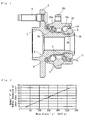
- the larger the hoop stress ⁇ by caulking the larger the amount ⁇ of radial expansion of the outer circumference portion of the inner ring 3, and that there is a substantially linearly proportional relation between them as shown in Fig. 2 .
- the applicant has had a conclusion that the hoop stress ⁇ generated in the inner ring 3 can be limited below a predetermined level by controlling the amount ⁇ of radial expansion of the inner ring 3.
- the hoop stress ⁇ caused in the outer circumferential portion 11 of the inner ring 3 generated by caulking process can be limited below 250 MPa by controlling the radial expansion ⁇ of the portion 11 of the inner ring 3 below 75 ⁇ m.
- the criterion for determining the acceptability is set at 75 ⁇ m, that is, when the radial expansion ⁇ of the inner ring 3 is below 75 ⁇ m, the product (inner ring 3) will be accepted, on the contrary, when the radial expansion ⁇ of the inner ring 3 is over 75 ⁇ m, the product will not be accepted.
- the limiting value of the hoop stress ⁇ is 250 MPa, this comes under a condition in which the inner ring 3 is exposed to the external circumstances. If the inner ring 3 is used within a circumstances sealed off from the external circumstances, the limiting value of the hoop stress may be set at 300 MPa.
- a stepped portion 11 b is formed on the outer diameter portion 11 at an inboard side from a portion 11a on which the seal 9 is fitted.
- the diameter of the stepped portion 11b is smaller than that of the portion 11a. This is because that the hoop stress ⁇ of the inner ring 3 generated is greatest at the outer circumferential surface.
- the amount ⁇ of radial expansion of the stepped portion 11b of the inner ring 3 is defined as a difference between a reading of a run-out of the stepped portion 11b of the inner ring 3 in its independent condition shown in Fig. 3(a) and a reading of a run-out of the stepped portion 11b of the inner ring 3 after being caulked shown in Fig. 3(b) .
- the amount ⁇ may be also defined as a difference between readings of run-outs of the stepped portion 11b before and after caulking process as shown in Figs. 4 (a) and (b) .
- annular recess 13 is formed around the outer circumferential portion of the axially extending portion 2b prior to the caulking at the end thereof corresponding to the inboard side end of the inner ring 3 as shown in Fig. 4(a) .
- the provision of the annular recess 13 makes it possible to suppress the deformation of the outer circumferential portion 11 of the inner ring 3 by caulking, especially the deformation of the stepped portion 11b at the inboard side thereof and thus to increase the strength of the caulked portion 2c as well as to reduce the hoop stress ⁇ generated in the inner ring 3.
- the strength of the caulked portion 2c is defined for example by an amount of axial displacement of the inner ring 3 generating the axial force more than 20 kN.
- the method for producing a bearing apparatus for a wheel of vehicle according to the present invention can be applied to the self-retaining type bearing apparatus of the first through third generations in which the inner ring is secure by press-fitting the inner ring onto the axially extending portion of the hub wheel and then by caulking the end of the axially extending portion of the hub wheel with plastic deformation.
Description
- The present invention relates to a method for producing a bearing apparatus of a vehicle such as an automobile for rotatably supporting a wheel relative to a suspension apparatus, and more particularly to a method for producing a bearing apparatus of a vehicle which can improve durability of an inner ring secured by caulking on a hub wheel of the bearing apparatus.
- There are two types of bearing apparatus of a vehicle, that is, for a drive wheel and for a driven wheel. Especially in the bearing apparatus of a vehicle for rotatably supporting a wheel relative to a suspension apparatus, it is required not only to be made at a low cost but to be light weight and small size for improving the fuel consumption. A representative example of the bearing apparatus for a driven wheel of vehicle of the prior art is shown in
Fig. 6 . Other examples of the bearing apparatus for a driven wheel of vehicle of the prior art are disclosed inUS 2002/0051597 A1 andEP 1 264 998 A - The bearing apparatus is that called as a third generation and has a
hub wheel 51, aninner ring 52, anouter ring 53, and doublerow rolling elements hub wheel 51 has at one end awheel mounting flange 55 integrally formed therewith, aninner raceway surface 51a, and an axially extendingportion 51b extending axially from theinner raceway surface 51a.Hub bolts 56 for securing a wheel on theflange 55 are arranged equidistantly along the periphery of theflange 55. - The
inner ring 52 formed with aninner raceway surface 52a on its outer circumferential surface is press-fitted onto the axially extendingportion 51b of thehub wheel 51. Theinner ring 52 is secured axially immovable to prevent it from being fallen off from the axially extendingportion 51b by acaulked portion 51c formed by plastically deforming the end portion of the axially extendingportion 51b radially outward. - The
outer ring 53 is integrally formed on its outer circumferential surface with abody mounting flange 53b and is also formed on its inner circumferential surface with double rowouter raceway surfaces row rolling elements outer raceway surfaces inner raceway surfaces - The
hub wheel 51 is made of carbon steel including carbon of 0.40∼0.80% by weight and formed with a layer (shown by cross-hatching) in a region from the base of thewheel mounting flange 55 to the axially extendingportion 51b through theinner raceway surface 51a hardened by high frequency induction hardening. Thecaulked portion 51c is remained as its original surface hardness after its forging. On the other hand, theinner ring 52 is made of high carbon chrome bearing steel such as SUJ2 and is hardened to its core by quenching. - Thus it is possible to realize a bearing apparatus for a wheel of vehicle of low cost and having a sufficient durability, to prevent generation of damage such as cracks on the
caulked portion 51c, and also to prevent generation of large change in the diameter of theinner ring 52 secured on thehub wheel 51 by thecaulked portion 51c. Also it is possible to reduce the potential of theinner ring 52 being damaged by the securing work, to maintain the preload at an appropriate value, and also to reduce the number of parts and steps of machining and assembly (see Japanese Laid-open Patent Publication No.129703/1999 - However, in the bearing apparatus of the prior art, it is impossible to prevent generation of hoop stress in the
outer diameter portion 57 of theinner ring 52 since the inner diameter of theinner ring 52 is expanded radially outward due to the radially outward plastic deformation of the axially extendingportion 51b near thecaulked portion 51c during formation of thecaulked portion 51c. - It has been proposed in order to reduce the hoop stress to suppress the amount of plastic deformation in caulking by changing the configuration of the end portion of the axially extending
portion 51b of thehub wheel 51. However, since it is required that thecaulked portion 51c has strength sufficient only to strongly secure theinner ring 52 even if a large momentum load is applied to the bearing apparatus, a conflicting problem i.e. suppressing the amount of plastic deformation as well as ensuring the strength of the caulked portion must be simultaneously solved. - When the hoop stress is caused in the
outer diameter portion 57 of theinner ring 52 and rust is generated in this portion, diffusible hydrogen existing in the circumstances would penetrate into the material of theinner ring 52 and destroy its metal grain boundary. Thus the so-called "delayed fracture" would be caused. - Heretofore there have been developed several methods for measuring the hoop stress itself, e.g. a method for irradiate X-ray on the
outer diameter portion 57 of theinner ring 52 in which maximum hoop stress is caused, or a method for sticking a strain gauge on the outer circumferential surface of theinner ring 52. However, neither method is simple and efficient in due consideration of mass production process. - It is, therefore, an object of the present invention to provide a method for producing a bearing apparatus for a wheel of vehicle with which the hoop stress generated in the inner ring can be limited during the caulking process below a predetermined level and can improve the durability and reliability of the inner ring.
- For achieving the object of the present invention, there is provided, according to claim 1, a method for producing a bearing apparatus for a wheel of vehicle having an outer member formed with double row outer raceway surfaces on the inner circumferential surface thereof; an inner member including a hub wheel and an inner ring, the hub wheel having at its one end a wheel mounting flange and an axially extending portion extending from the wheel mounting flange, the inner ring being fitted onto the axially extending portion, and the hub wheel and the inner ring being formed on their outer circumferential surfaces with double row inner raceway surfaces respectively opposing to the double row outer raceway surfaces; and double row rolling elements freely rollably held by cages between the opposing double row inner and outer raceway surfaces; wherein the method comprises the steps of securing the inner ring axially immovable by plastically deforming the end portion of the axially extending portion radially outward, and limiting a hoop stress in the inner member below a predetermined level by measuring a radial expansion of the outer circumferential surface of the inner ring before and after said plastic deformation thereof and by controlling the amount of the radial expansion of the inner ring on the basis of predetermined relation between the hoop stress and the amount of radial expansion of the inner ring.
- According to the invention, since an outer diameter of the inner ring before and after said plastic deformation thereof is measured, the amount of the radial expansion of the inner ring is controlled on the basis of predetermined relation between the hoop stress and the amount of radial expansion of the inner ring, and a hoop stress in the inner member is limited below a predetermined level, it is possible to very easily and exactly control the hoop stress in the inner ring caulked on the hub and to prevent generation of the cracking of the inner ring or the delayed fracture, and thus to provide a bearing apparatus having superior durability and reliability of the inner ring.
- Preferably, the relation between the amount of radial expansion of the inner ring and the hoop stress generated in the inner ring is defined by a linear proportional relation. This enables the hoop stress itself generated in the inner ring to be measured easily and exactly.
- According to the present invention, the hub wheel may be made of medium carbon steel including carbon of 0.40∼0.80% by weight and a region from the inner raceway surface to the axially extending portion of the hub wheel is formed with a hardened layer having surface hardness 58-64 HRC by high frequency induction hardening, the caulked portion is remained as a non-quenching portion having surface hardness below 25 HRC, and the inner ring is made of high carbon chrome bearing steel and is hardened to its core by dipping quenching to have surface hardness of 58-64 HRC. This enables the hoop stress generated in the inner ring by caulking to be easily and exactly limited below a predetermined level e.g. 250 MPa.
- According to the present invention, the outer circumferential surface of inboard side portion of the inner ring may be formed with a stepped portion of a smaller diameter. This enables the amount of expansion of the stepped portion exposed to rusty circumstances to be controlled and also the hoop stress to be limited below a predetermined level.
- According to the present invention, an annular recess can be formed around the outer circumferential portion of the axially extending portion prior to the caulking at the end thereof corresponding to the inboard side end of the inner ring. This enables the deformation of the outer circumferential surface, especially the inboard side stepped portion to be suppressed, and also the strength of the caulked portion to be increased as well as the hoop stress generated in the inner ring to be reduced.
- The method for producing a bearing apparatus for a wheel of vehicle of the present invention having an outer member formed with double row outer raceway surfaces on the inner circumferential surface thereof; an inner member including a hub wheel and an inner ring, the hub wheel having at its one end a wheel mounting flange and an axially extending portion extending from the wheel mounting flange, the inner ring being fitted onto the axially extending portion, and the hub wheel and the inner ring being formed on their outer circumferential surfaces with double row inner raceway surfaces respectively opposing to the double row outer raceway surfaces; and double row rolling elements freely rollably held by cages between the opposing double row inner and outer raceway surfaces; comprises the steps of securing the inner ring axially immovable by plastically deforming the end portion of the axially extending portion radially outward, and limiting a hoop stress in the inner member below a predetermined level by measuring a radial expansion of the outer circumferential surface of the inner ring before and after said plastic deformation thereof and by controlling the amount of the radial expansion of the inner ring on the basis of predetermined relation between the hoop stress and the amount of radial expansion of the inner ring. Accordingly, it is possible to very easily and exactly control the hoop stress in the inner ring caulked on the hub and to prevent generation of the cracking of the inner ring or the delayed fracture, and thus to provide a bearing apparatus having superior durability and reliability of the inner ring. Best Mode for carrying out the Invention
- The best mode for carrying out the present invention is a method for producing a bearing apparatus for a wheel of vehicle which has an outer member having a body mounting flange integrally formed therewith and double row outer raceway surfaces formed on the inner circumferential surface thereof; an inner member including a hub wheel and an inner ring, the hub wheel having at its one end a wheel mounting flange, an inner raceway surface opposing to one of the double row outer raceway surfaces, and an axially extending portion extending from the inner raceway surface, the inner ring being fitted onto the axially extending portion and being formed on their outer circumferential surfaces with an another inner raceway surfaces opposing to the other of the double row outer raceway surfaces; and double row rolling elements freely rollably held by cages between the opposing double row inner and outer raceway surfaces; wherein the method comprises the steps of securing the inner ring axially immovable by plastically deforming the end portion of the axially extending portion radially outward, and limiting a hoop stress in the inner member below a predetermined level by measuring a radial expansion of the outer circumferential surface of the inner ring before and after said plastic deformation thereof and by controlling the amount of the radial expansion of the inner ring on the basis of predetermined relation between the hoop stress and the amount of radial expansion of the inner ring.
- Additional advantages and features of the present invention will become apparent from the subsequent description and the appended claims, taken in conjunction with the accompanying drawings, wherein:
- Fig. 1
- is a longitudinal section view showing a first embodiment of a bearing apparatus for a wheel of vehicle produced according to the present invention;
- Fig. 2
- is a graph showing a relation between the hoop stress generated in the inner ring by caulking and the amount of radial expansion of the outer circumferential surface of the inner ring;
- Figs. 3(a)
- and 3(b) are explanatory drawings wherein
Fig. 3 (a) shows a method for measuring the run-out of the outer circumferential surface of the inner ring in its independent condition andFig. 3 (b) shows a method for measuring the run-out of the outer circumferential surface of the inner ring after being caulked; - Figs. 4(a)
- and 4(b) are explanatory drawings wherein
Fig. 4(a) shows a method for measuring the amount of the outer circumferential surface of the inner ring before caulking andFig. 4(b) shows a method for measuring the amount of expansion of the outer circumferential surface of the inner ring after caulking; - Fig. 5
- is an explanatory drawing showing a position for measuring the amount of the outer circumferential surface of the inner ring; and
- Fig. 6
- is a longitudinal section view showing a bearing apparatus for a wheel of vehicle of the prior art.
-
Fig. 1 is a longitudinal cross-section of a first embodiment of a bearing apparatus for a wheel of vehicle produced according to the present invention. In the description below, a term "outboard side" (a left-hand side in drawings) of the apparatus denotes a side which is positioned outside of the vehicle body and a term "inboard side" (a righthand side in drawings) of the apparatus denotes a side which is positioned inside of the body when the bearing apparatus is mounted on the vehicle body. - The bearing apparatus for a wheel of vehicle is that called as a third generation and comprises an inner member 1, an
outer member 10, and a double row rolling elements (balls) 6, 6 rollably contained between the inner andouter members 1 and 10. The inner member 1 comprises ahub wheel 2 and aninner ring 3 press-fitted onto thehub wheel 2 via a predetermined interference. - The
hub wheel 2 has awheel mounting flange 4 for mounting a wheel (not shown) integrally formed therewith at the outboard side end, andhub bolts 5 for securing a wheel on theflange 4 are arranged equidistantly along the periphery of theflange 4. Thehub wheel 2 is formed with aninner raceway surface 2a on its outer circumferential surface and axially extendingcylindrical portion 2b axially extending from theinner raceway surface 2a. Aninner ring 3 formed with aninner raceway surface 3a on its outer circumferential surface is press-fitted onto the axially extendingportion 2b of thehub wheel 2. Theinner ring 3 is secured axially immovable to prevent it from being fallen off from theaxially extending portion 2b by a caulkedportion 2c formed by plastically deforming the end portion of theaxially extending portion 2b radially outward. - The
outer member 10 is integrally formed on its outer circumferential surface with abody mounting flange 10b for mounting thisouter member 10 on a body (not shown) and is also formed on its inner circumferential surface with double rowouter raceway surfaces 10a and. Doublerow rolling elements inner raceway surfaces cages Seals outer member 10 to prevent leak of grease contained within the bearing as well as ingress of rain water or dusts from outside. - The illustrated bearing apparatus is that is the so-called "third generation type", however the present invention can also be applied to bearing apparatus of the first and second generation in which a pair of inner rings are fitted on the axially extending portion of the hub wheel. In the illustrated embodiment, a double row angular ball bearing using balls as rolling elements is shown, however other bearing such as a double row tapered roller bearing using tapered rollers as the rolling elements may be adopted.
- The
hub wheel 2 is made of medium carbon steel including carbon of 0.40∼0.80% by weight such as S53C and formed withhardened layer 20 having a surface hardness 58-64 HRC by high frequency induction hardening at theinner raceway surface 2a of the outboard side, a seal land portion with which the sealing means 8 contacts, and theaxially extending portion 2b. The caulkedportion 2c is remained as a no-quenching portion having a surface hardness below 25 HRC after its forging. On the other hand, theinner ring 3 is made of high carbon chrome bearing steel such as SUJ2 and is hardened to its core by dipping quenching to have a surface hardness of 58-64 HRC. - The
outer member 10 is made of medium carbon steel including carbon of 0.40∼0.80% by weight such as S53C and itsdouble raceway surfaces - The present applicant analyzed causes of generation of the hoop stress in the
outer diameter portion 11 of theinner ring 3 and investigated the relation between the hoop stress σ generated by the caulking process and the amount δ of radial expansion of theouter diameter portion 11 of theinner ring 3. As a result of which, it has found that the larger the hoop stress σ by caulking, the larger the amount δ of radial expansion of the outer circumference portion of theinner ring 3, and that there is a substantially linearly proportional relation between them as shown inFig. 2 . Accordingly, the applicant has had a conclusion that the hoop stress σ generated in theinner ring 3 can be limited below a predetermined level by controlling the amount δ of radial expansion of theinner ring 3. When theinner ring 3 is used in a condition exposed to the external environment, it is necessary to limit the hoop stress below 250 MPa. - As shown in
Fig. 2 , it can be seen that the hoop stress σ caused in the outercircumferential portion 11 of theinner ring 3 generated by caulking process can be limited below 250 MPa by controlling the radial expansion δ of theportion 11 of theinner ring 3 below 75 µ m. Thus the criterion for determining the acceptability is set at 75 µm, that is, when the radial expansion δ of theinner ring 3 is below 75 µ m, the product (inner ring 3) will be accepted, on the contrary, when the radial expansion δ of theinner ring 3 is over 75 µ m, the product will not be accepted. By adopting such a method, it is possible to very easily and exactly control the hoop stress σ of theinner ring 3 caulked onto thehub wheel 2 and thus to limit the hoop stress σ of theinner ring 3 below the predetermined level. Accordingly it is possible to prevent generation of cracking or delayed fracture of theinner ring 3 and thus to provide a bearing apparatus for a wheel of vehicle which can improve the durability and reliability of theinner ring 3 caulked on thehub wheel 2. - In the example above, although it is described that the limiting value of the hoop stress σ is 250 MPa, this comes under a condition in which the
inner ring 3 is exposed to the external circumstances. If theinner ring 3 is used within a circumstances sealed off from the external circumstances, the limiting value of the hoop stress may be set at 300 MPa. - In the illustrated embodiment, as best shown in
Fig. 3 (b) , a steppedportion 11 b is formed on theouter diameter portion 11 at an inboard side from aportion 11a on which theseal 9 is fitted. The diameter of the steppedportion 11b is smaller than that of theportion 11a. This is because that the hoop stress σ of theinner ring 3 generated is greatest at the outer circumferential surface. Thus it is possible to limit the hoop stress σ of theinner ring 3 below the predetermined level (value) by controlling the amount δ of the radial expansion of the steppedportion 11b at least exposed to the external circumstances. Of course it is also possible to adopt a structure not having the steppedportion 11b. - The amount δ of radial expansion of the stepped
portion 11b of theinner ring 3 is defined as a difference between a reading of a run-out of the steppedportion 11b of theinner ring 3 in its independent condition shown inFig. 3(a) and a reading of a run-out of the steppedportion 11b of theinner ring 3 after being caulked shown inFig. 3(b) . The amount δ may be also defined as a difference between readings of run-outs of the steppedportion 11b before and after caulking process as shown inFigs. 4 (a) and (b) . In order to improve the reliability of measured data, it is preferable to previously set the measuring point P at a position apart a distance "e" from theend 3b of theinner ring 3. - Since it has been found that the amount δ of radial expansion of the
inner ring 3 is larger toward the inboard side thereof, anannular recess 13 is formed around the outer circumferential portion of theaxially extending portion 2b prior to the caulking at the end thereof corresponding to the inboard side end of theinner ring 3 as shown inFig. 4(a) . The provision of theannular recess 13 makes it possible to suppress the deformation of the outercircumferential portion 11 of theinner ring 3 by caulking, especially the deformation of the steppedportion 11b at the inboard side thereof and thus to increase the strength of the caulkedportion 2c as well as to reduce the hoop stress σ generated in theinner ring 3. The strength of the caulkedportion 2c is defined for example by an amount of axial displacement of theinner ring 3 generating the axial force more than 20 kN. - The method for producing a bearing apparatus for a wheel of vehicle according to the present invention can be applied to the self-retaining type bearing apparatus of the first through third generations in which the inner ring is secure by press-fitting the inner ring onto the axially extending portion of the hub wheel and then by caulking the end of the axially extending portion of the hub wheel with plastic deformation.
- The present invention has been described with reference to the preferred embodiments. Obviously, modifications and alternations will occur to those of ordinary skill in the art upon reading and understanding the preceding detailed description. It is intended that the present invention be construed as including all such alternations and modifications insofar as they come within the scope of the appended claims.
Claims (5)
- A method for producing a bearing apparatus for a wheel of vehicle having
an outer member (10) formed with double row outer raceway surfaces (10a, 10a) on the inner circumferential surface thereof;
an inner member (1) including a hub wheel (2) and an inner ring (3), the hub wheel (2) having at its one end a wheel mounting flange (4) and an axially extending portion (2b) extending from the wheel mounting flange (4), the inner ring (3) being fitted onto the axially extending portion (2b), and the hub wheel (2) and the inner ring (3) being formed on their outer circumferential surfaces with double row inner raceway surfaces (2a, 3a) respectively opposing to the double row outer raceway surfaces (10a, 10a); and
double row rolling elements (6, 6) freely rollably held by cages (7,7) between the opposing double row inner and outer raceway surfaces (2a, 3a and 10a, 10a);
wherein the method comprises the steps of:- securing the inner ring (3) axially immovable by plastically deforming the end portion of the axially extending portion (2b) radially outward, and- limiting a hoop stress in the inner member (3) below a predetermined level by measuring an outer diameter of the inner ring (3) before and after said plastic deformation thereof and by controlling the amount of the radial expansion of the inner ring (3) on the basis of predetermined relation between the hoop stress and the amount of radial expansion of the inner ring (3). - Method according to claim 1, wherein the relation between the amount of radial expansion of the inner ring (3) and the hoop stress generated in the inner ring (3) is defined by a linear proportional relation.
- Method according to claim 1 or 2, wherein the hub wheel (2) is made of medium carbon steel including carbon of 0.40~0.80% by weight and a region from the inner raceway surface (2a) to the axially extending portion (2b) of the hub wheel (2) is formed with a hardened layer having surface hardness 58~64 HRC by high frequency induction hardening, the caulked portion (2c) is remained as a non-quenching portion having surface hardness below 25 HRC, and the inner ring (3) is made of high carbon chrome bearing steel and is hardened to its core by dipping quenching to have surface hardness of 58-64 HRC.
- Method according to any one of claims 1 through 3, wherein the outer circumferential surface of inboard side portion of the inner ring (3) is formed with a stepped portion of a smaller diameter.
- Method according to any one of claims 1 through 4, wherein an annular recess (13) is formed around the outer circumferential portion of the axially extending portion (2b) prior to the caulking at the end thereof corresponding to the inboard side end of the inner ring (3).
Applications Claiming Priority (1)
| Application Number | Priority Date | Filing Date | Title |
|---|---|---|---|
| JP2004226282A JP3917992B2 (en) | 2004-08-03 | 2004-08-03 | Wheel bearing device |
Publications (3)
| Publication Number | Publication Date |
|---|---|
| EP1624205A2 EP1624205A2 (en) | 2006-02-08 |
| EP1624205A3 EP1624205A3 (en) | 2006-09-27 |
| EP1624205B1 true EP1624205B1 (en) | 2010-05-26 |
Family
ID=35219258
Family Applications (1)
| Application Number | Title | Priority Date | Filing Date |
|---|---|---|---|
| EP05016265A Active EP1624205B1 (en) | 2004-08-03 | 2005-07-27 | Bearing apparatus for a wheel of vehicle |
Country Status (5)
| Country | Link |
|---|---|
| US (1) | US7607838B2 (en) |
| EP (1) | EP1624205B1 (en) |
| JP (1) | JP3917992B2 (en) |
| CN (1) | CN100480528C (en) |
| DE (1) | DE602005021434D1 (en) |
Families Citing this family (6)
| Publication number | Priority date | Publication date | Assignee | Title |
|---|---|---|---|---|
| JP4562025B2 (en) * | 2004-08-16 | 2010-10-13 | Ntn株式会社 | Wheel bearing device |
| JP2007239965A (en) * | 2006-03-13 | 2007-09-20 | Ntn Corp | Bearing device for wheel |
| WO2007125646A1 (en) * | 2006-04-25 | 2007-11-08 | Ntn Corporation | Bearing device for wheel |
| US8516705B2 (en) * | 2007-10-02 | 2013-08-27 | Nsk Ltd. | Method of manufacturing bearing ring member for rolling bearing unit |
| JP7290086B2 (en) * | 2019-09-06 | 2023-06-13 | 日本精工株式会社 | HUB UNIT BEARING AND MANUFACTURING METHOD THEREOF |
| DE102019218794A1 (en) * | 2019-12-03 | 2021-06-10 | Thyssenkrupp Ag | Process for increasing the load-bearing capacity and rolling device for hard rolling a surface-hardened roller bearing raceway |
Family Cites Families (12)
| Publication number | Priority date | Publication date | Assignee | Title |
|---|---|---|---|---|
| JP3855315B2 (en) * | 1996-09-25 | 2006-12-06 | 日本精工株式会社 | Manufacturing method of wheel bearing rolling bearing unit |
| JP3622458B2 (en) | 1997-08-28 | 2005-02-23 | 日本精工株式会社 | Rolling bearing unit for wheel support |
| DE69831102T2 (en) * | 1997-01-17 | 2006-04-20 | Nsk Ltd. | Bearing unit for a vehicle wheel suspension |
| DE60002796T2 (en) | 1999-08-06 | 2004-04-01 | Koyo Seiko Co., Ltd. | bearing device |
| US6575637B1 (en) * | 1999-09-10 | 2003-06-10 | Ntn Corporation | Brake rotor and wheel bearing assembly |
| EP1110756B1 (en) * | 1999-12-16 | 2008-02-20 | Nsk Ltd | Wheel-support rolling bearing unit and a method manufacturing the same |
| DE60005124T2 (en) * | 1999-12-20 | 2004-03-25 | Nsk Ltd. | Roller bearing unit and process for its manufacture |
| US6702472B2 (en) | 2000-08-24 | 2004-03-09 | Ntn Corporation | Wheel bearing device and method of crimping the same |
| JP4543549B2 (en) * | 2000-12-21 | 2010-09-15 | 日本精工株式会社 | Assembly method for automotive hub unit |
| JP4710179B2 (en) | 2001-07-03 | 2011-06-29 | 日本精工株式会社 | Manufacturing method of bearing unit for wheel drive wheel |
| JP4326184B2 (en) * | 2002-03-27 | 2009-09-02 | 株式会社ジェイテクト | Method and apparatus for assembling rolling bearing device |
| JP4278542B2 (en) | 2004-03-12 | 2009-06-17 | 日本精工株式会社 | Manufacturing method of wheel supporting hub unit |
-
2004
- 2004-08-03 JP JP2004226282A patent/JP3917992B2/en active Active
-
2005
- 2005-07-27 DE DE602005021434T patent/DE602005021434D1/en active Active
- 2005-07-27 EP EP05016265A patent/EP1624205B1/en active Active
- 2005-08-02 US US11/195,798 patent/US7607838B2/en active Active
- 2005-08-03 CN CN200510089043.2A patent/CN100480528C/en active Active
Also Published As
| Publication number | Publication date |
|---|---|
| CN100480528C (en) | 2009-04-22 |
| US20060029316A1 (en) | 2006-02-09 |
| EP1624205A2 (en) | 2006-02-08 |
| EP1624205A3 (en) | 2006-09-27 |
| JP2006046434A (en) | 2006-02-16 |
| US7607838B2 (en) | 2009-10-27 |
| DE602005021434D1 (en) | 2010-07-08 |
| CN1734112A (en) | 2006-02-15 |
| JP3917992B2 (en) | 2007-05-23 |
Similar Documents
| Publication | Publication Date | Title |
|---|---|---|
| US7648284B2 (en) | Bearing apparatus for a wheel of vehicle | |
| JP2002139060A (en) | Wheel bearing device | |
| EP1624205B1 (en) | Bearing apparatus for a wheel of vehicle | |
| EP1721757B1 (en) | Bearing apparatus for a wheel of vehicle | |
| US7635226B2 (en) | Bearing apparatus for a wheel of vehicle | |
| JP2006349059A (en) | Bearing device for wheel | |
| US7665900B2 (en) | Vehicle wheel bearing apparatus | |
| EP1795771B1 (en) | Bearing device for wheel | |
| JP2006316803A (en) | Bearing device for wheel | |
| JP4573200B2 (en) | Wheel bearing device | |
| JP2006046401A (en) | Bearing device for wheel | |
| JP4321714B2 (en) | Wheel bearing device | |
| JP4780707B2 (en) | Wheel bearing device | |
| JP4632305B2 (en) | Wheel bearing device | |
| JP2005349928A (en) | Bearing device for wheel | |
| JP2006052752A (en) | Bearing unit for wheel | |
| JP2007106412A (en) | Bearing device for vehicle wheel | |
| JP2007024208A (en) | Bearing device for wheel | |
| JP4034799B2 (en) | Wheel bearing device | |
| JP2004183815A (en) | Bearing device for wheel | |
| JP2006316874A (en) | Bearing device for wheel | |
| JP4521878B2 (en) | Wheel bearing device | |
| JP2009293731A (en) | Bearing device for wheel | |
| JP2006316875A (en) | Bearing device for wheel | |
| JP2006090353A (en) | Vehicular bearing device |
Legal Events
| Date | Code | Title | Description |
|---|---|---|---|
| PUAI | Public reference made under article 153(3) epc to a published international application that has entered the european phase |
Free format text: ORIGINAL CODE: 0009012 |
|
| AK | Designated contracting states |
Kind code of ref document: A2 Designated state(s): AT BE BG CH CY CZ DE DK EE ES FI FR GB GR HU IE IS IT LI LT LU LV MC NL PL PT RO SE SI SK TR |
|
| AX | Request for extension of the european patent |
Extension state: AL BA HR MK YU |
|
| PUAL | Search report despatched |
Free format text: ORIGINAL CODE: 0009013 |
|
| AK | Designated contracting states |
Kind code of ref document: A3 Designated state(s): AT BE BG CH CY CZ DE DK EE ES FI FR GB GR HU IE IS IT LI LT LU LV MC NL PL PT RO SE SI SK TR |
|
| AX | Request for extension of the european patent |
Extension state: AL BA HR MK YU |
|
| RIC1 | Information provided on ipc code assigned before grant |
Ipc: F16C 19/18 20060101AFI20051111BHEP Ipc: F16C 43/04 20060101ALI20060818BHEP Ipc: F16C 35/063 20060101ALI20060818BHEP |
|
| 17P | Request for examination filed |
Effective date: 20061206 |
|
| 17Q | First examination report despatched |
Effective date: 20070109 |
|
| AKX | Designation fees paid |
Designated state(s): DE FR |
|
| GRAP | Despatch of communication of intention to grant a patent |
Free format text: ORIGINAL CODE: EPIDOSNIGR1 |
|
| GRAS | Grant fee paid |
Free format text: ORIGINAL CODE: EPIDOSNIGR3 |
|
| GRAA | (expected) grant |
Free format text: ORIGINAL CODE: 0009210 |
|
| AK | Designated contracting states |
Kind code of ref document: B1 Designated state(s): DE FR |
|
| REF | Corresponds to: |
Ref document number: 602005021434 Country of ref document: DE Date of ref document: 20100708 Kind code of ref document: P |
|
| PLBE | No opposition filed within time limit |
Free format text: ORIGINAL CODE: 0009261 |
|
| STAA | Information on the status of an ep patent application or granted ep patent |
Free format text: STATUS: NO OPPOSITION FILED WITHIN TIME LIMIT |
|
| 26N | No opposition filed |
Effective date: 20110301 |
|
| REG | Reference to a national code |
Ref country code: DE Ref legal event code: R097 Ref document number: 602005021434 Country of ref document: DE Effective date: 20110228 |
|
| REG | Reference to a national code |
Ref country code: FR Ref legal event code: PLFP Year of fee payment: 12 |
|
| REG | Reference to a national code |
Ref country code: FR Ref legal event code: PLFP Year of fee payment: 13 |
|
| REG | Reference to a national code |
Ref country code: FR Ref legal event code: PLFP Year of fee payment: 14 |
|
| PGFP | Annual fee paid to national office [announced via postgrant information from national office to epo] |
Ref country code: FR Payment date: 20230608 Year of fee payment: 19 |
|
| PGFP | Annual fee paid to national office [announced via postgrant information from national office to epo] |
Ref country code: DE Payment date: 20230531 Year of fee payment: 19 |