EP2583531B1 - Mobiles kommunikationsnetz mit verteilten verarbeitungsressourcen - Google Patents
Mobiles kommunikationsnetz mit verteilten verarbeitungsressourcen Download PDFInfo
- Publication number
- EP2583531B1 EP2583531B1 EP11724390.7A EP11724390A EP2583531B1 EP 2583531 B1 EP2583531 B1 EP 2583531B1 EP 11724390 A EP11724390 A EP 11724390A EP 2583531 B1 EP2583531 B1 EP 2583531B1
- Authority
- EP
- European Patent Office
- Prior art keywords
- radio
- transmit
- radio signals
- antenna
- processing
- Prior art date
- Legal status (The legal status is an assumption and is not a legal conclusion. Google has not performed a legal analysis and makes no representation as to the accuracy of the status listed.)
- Active
Links
Images






Classifications
-
- H—ELECTRICITY
- H04—ELECTRIC COMMUNICATION TECHNIQUE
- H04W—WIRELESS COMMUNICATION NETWORKS
- H04W88/00—Devices specially adapted for wireless communication networks, e.g. terminals, base stations or access point devices
- H04W88/08—Access point devices
- H04W88/085—Access point devices with remote components
Definitions
- the field of the invention relates to a mobile communications network and to a method for processing radio signals for the mobile communications network.
- the field of the present invention also relates to a computer program product enabling a foundry to carry out the manufacture of a chip for the mobile communications network, and to a computer program product enabling a mobile communications network to execute a method for processing radio signals.
- BTS Hoteling In the BTS Hoteling approach, the remote radio head is moved further from the remainder of the BTS, to enable the remainder of the BTS to be co-located with similar parts of other BTSs (for an entire city, for example) to form a BTS hotel.
- the BTS Hoteling approach involves all of the baseband/control/transport parts of a number of base stations being housed at the same location (e.g. for ease of maintenance and to save housing costs).
- the BTS hotel and the remote radio head(s) are connected by means of dedicated fibre-optic or microwave point-to-point links, for example, from the BTS baseband sections to their respective remote radio heads.
- each BTS site should be dimensioned for the amount of communication traffic during peak hours.
- a large portion of the traffic handling capacity of different ones of the BTS sites is not utilized during off-peak hours.
- the hours that constitute 'peak' hours will vary from site to site; for example, a city centre site may experience its peak hours during the working day, whereas a suburban site may experience its peak hours during the morning and evening commuting times.
- US 2009/0170543 A1 discloses a cellular communications system according to the preamble of claim 1.
- the cellular communications system has a centralized base station hotel in communication with a plurality of radio heads over a transport medium, and the centralized radio processing portion compensates for a fixed delay associated with the transport medium coupling the centralized radio processing portion and one of the remote air interface radio portions.
- US 2010/0099426 A1 discloses a telecommunication network including: a radio access network and a network switching subsystem operable for communication with the radio access network and with a demand-driven, dynamically-configurable IP based computing infrastructure.
- China Mobile Research Institute “C-RAN; The road towards Green RAN ", discloses a real-time Cloud infrastructure RAN (C-RAN).
- US2008/181182 A1 discloses a network architecture comprising a baseband unit, a plurality of remote radio heads, a timing generator configured to generate a timing signal for synchronizing the transmission of the signals from the remote radio heads.
- the present invention is disclosed according to a mobile communications network according to independent Claim 1, a method for processing radio signals for a mobile communications network according to independent Claim 8 and according to a computer program product according to independent Claim 14.
- the present invention shows a mobile communications network that comprises a plurality of radio heads, a cloud processing architecture, and a plurality of radio head links.
- the plurality of radio heads is provided for transceiving radio signals and for converting the radio signals between baseband representations of the radio signals and radio frequency representations of the radio signals.
- the cloud processing architecture is provided for processing the baseband representations of the radio signals.
- the cloud processing architecture is ad-hoc shareable on demand between different ones of the plurality of radio heads.
- An active antenna comprises a transmit/receive module connected to a plurality of antenna elements, the transmit/receive module being connected to an integrated absolute timing reference and to a packet analyser, wherein the packet analyser receives packets from a network interface that the active antenna has received from an asynchronous switched network (305), extracts a timing information from said packets and forwards the timing information to the transmit/receive module, and wherein the timing information is compared with the current time provided by the absolute timing reference, a transmission of a portion of the transmit signal pertaining to wireless communication being initiated when said current time matches said timing information.
- the plurality of radio head links is provided between the plurality of radio heads and the cloud processing architecture.
- This proposed architecture of a mobile communications network acknowledges that a given mobile communications network is never fully utilised at all of its BTS sites simultaneously. It may be, for example, that a suburban part of the mobile communications network is heavily loaded as commuters enter and leave the city in the morning and evening, with the city centre part of the mobile communications network being relatively lightly loaded at this time. Likewise, the opposite will probably be true during the main business day.
- the remote radio head is defined as a unit that typically combines the following components: power supply, transceiver, amplifier, power amplifier and/or low-noise amplifier, and duplex filter. This is, however, only exemplary.
- the remote radio head is installed close to the antenna, or the remote radio head may be merged with the actual antenna, resulting in an active antenna.
- the term "radio head” refers to both, a separate remote radio head and the functionality of a radio head integrated into the active antenna.
- baseband describes, from a perspective of the radio head, a frequency range at a core-network facing side of the radio head. Accordingly, the baseband frequency range is lower in frequency than the radio frequency range, It is however, not necessary for the baseband frequency range, as defined and used herein, to coincide with a baseband frequency range used in other parts of the mobile communications network.
- baseband as used in this disclosure could also be applied to, e.g., an intermediate frequency.
- the radio heads are capable of transeiving radio signals which means that they are capable of transmitting radio signals, receiving radio signals, or both. Converting the radio signals between baseband representations of the radio signals and radio signal representations of the radio signals is performed by the radio heads so that each radio head usually provides the hardware necessary for converting the radio signals. However, converting the radio signals between baseband and radio frequency is typically straightforward so that the radio head can be relatively "dumb".
- the cloud processing architecture makes it possible to process the baseband representations of the radio signals belonging to different ones of the plurality of radio heads at a reduced number of processing entities, compared to the 1-to-1 approach of the prior art.
- the processing entities that form the cloud processing architecture are sharable between the different ones of the plurality of radio heads.
- the cloud processing architecture may comprise non-dedicated processing resources which are shareable between different ones of the plurality of radio heads.
- the mobile communications network may further comprise a base station and a packet-based base station link between the base station and the cloud processing architecture.
- This mobile communications network structure allows outsourcing of e.g. computationally intensive signal processing tasks from the base station to the cloud processing architecture.
- each base station may have a basic processing capacity sufficient for off-peak demand.
- the packet-based base station link makes it possible to assign a portion of the signal processing tasks to the cloud processing architecture during peak demand.
- the mobile communications network may further comprise a radio head timing reference.
- the radio head timing reference may be used to synchronise the transmission and/or the reception of the radio signals at the plurality of radio heads.
- the radio head timing reference is usually integrated with at least one radio head of the plurality of radio heads.
- the radio head timing reference may be installed in close vicinity to at least one radio head of the plurality of radio heads.
- the radio head timing reference may be useful to compensate for delays introduced by the plurality of radio head links, in particular, when these delays are time-varying and/or random.
- the mobile communications network may further comprise a base station timing reference and/or a cloud processing architecture timing reference.
- the various timing references may be used to synchronise the shared processing of the baseband representations of the radio signals.
- the mobile communications network may further comprise a public switched telephone network (PSTN) link as a part of the plurality of radio head links.
- PSTN public switched telephone network
- Utilisation of an already existing PSTN link may significantly reduce the costs of the plurality of radio head links.
- a major part of the distance between an individual one of the plurality of radio heads and the cloud processing architecture can be covered by the PSTN link.
- the plurality of radio heads will comprise at least one of an up-convertor and a down-convertor adapted to frequency-convert the radio signals.
- Modern mobile communications networks typically use a frequency between approximately 500 MHz and 5 GHz for the communication between the plurality of radio heads and the mobile stations (handsets).
- the transmission of the radio signals over the plurality of radio head links at these frequencies would make high demands on the radio head links. With the frequency-conversion being performed at the plurality of radio head links, these high demands may be substantially relaxed.
- the demand for allocating a share of the cloud processing architecture may be based on a number of users connected to a given radio head.
- the demand may be determined by software running in the cloud processing architecture.
- the demand for allocating a share of the cloud processing architecture may be based on an amount of data downloaded or uploaded via the radio head. This enables, under normal circumstances, that an individual one of the plurality of radio heads has a share of the cloud processing architecture at its disposal sufficient for its signal processing needs at a given time.
- the disclosure also teaches a method for processing radio signals for a mobile communications network.
- the method comprises:
- the plurality of non-dedicated processing resources may he organised as a cloud processing architecture.
- the method may further comprise passing packets of base station-related data between a base station and the plurality of non-dedicated processing resources via a packet-based base station link.
- the method may further comprise providing a radio head timing reference locally to at least one radio head in the plurality of radio heads.
- a base station timing reference may be provided locally to a base station that is part of the mobile communications network, or a timing reference may be provided locally to at least one non-dedicated processing resource of the plurality of non-dedicated resources.
- the packets of the baseband representations of the radio signals may be passed over a PSTN network.
- the method may further comprise frequency-converting the radio signals at a radio head of the plurality of remote radio heads.
- the demand for allocating a share of the cloud processing architecture may be based upon a number of users connected to a given radio head. In addition, or alternatively, the demand for allocating a share of the cloud processing architecture may be based upon an amount of data downloaded or uploaded via the radio head.
- the disclosure also teaches a computer program product comprising a non-transitory computer-usable medium having control logic stored therein for causing a computer to manufacture a mobile communications network comprising:
- a computer program product which comprises a non-transitory computer-usable medium having control logic stored therein for causing a mobile communications network to execute a method for processing baseband representations of radio signals for a mobile communications network comprising:
- At least parts of the mobile communications network and the method for process radio signals may be implemented in software, in hardware, or as a combination of both software and hardware.
- FIG 1 shows a typical example of an existing base station architecture when utilizing a remote radio head 107
- the remote radio head (RRH) 107 is connected directly to a baseband card/module 114 of a base station or a base station rack 112, typically using a fibre-optic cable 108 to transfer the high-speed digital signals which describe the carrier information to be transmitted (e.g. using OBSAI protocol or CPRI protocol).
- the remote radio head 107 also requires a power feed to provide electrical power to the remote radio head 107.
- the remote radio head 107 receives electrical power by means of a power supply cable 109 and a power supply unit 115 of the base station 112.
- the electrical power could also be supplied to the remote radio head 107 via an AC feed from a mains supply that is local to the remote radio head 107.
- AC electrical power is, in this case, converted to DC electrical power by means of a local power supply near or within the remote radio head 107.
- the local power supply may be chosen if the distance between the remote radio head 107 and the remainder of the base station 112 is large.
- the base station rack 112 comprises a transport section 116 which is used to connect the base station rack 112 with a backhaul network.
- the backhaul network is typically based on T1/E1 lines or microwave links.
- the digital signals are transferred directly from the base station's baseband circuits to the remote radio head 107 with a defined (known) distance or transmission delay between the baseband circuits and the remote radio head 107.
- This transmission delay should be known, and taken into account by the BTS (or sufficiently small as to be insignificant), as the delay between packets being transmitted by the transmit antenna and received by the receive antenna (which are typically one and the same antenna) is a determinant of the cell's radius. If the transmission delay between the baseband circuits and the remote radio head is not taken into account, in both the transmit (downlink) and receive (uplink) directions, then the cell's radius will be unnecessarily compromised (reduced), irrespective of the power level transmitted. It will also, in many systems, have an impact upon handover performance and this will, in turn, impact the quality of service experienced by a user of the system.
- a local absolute timing reference is provided, often utilizing a GPS receiver.
- the base station or base station rack 112 shown in Figure 1 comprises a local timing module 113.
- a local absolute timing reference utilizing a GPS receiver provides a very accurate indication of absolute time, typically based on Coordinated Universal Time (UTC) or Greenwich Mean Time (GMT), and enables all of the base stations in a mobile communications network to be accurately synchronized. This is necessary in some CDMA systems, for example, to enable soft-handover to operate correctly.
- This timing information forms the basis for the timing used by the remote radio head 107, since the BTS rack 112 and the remote radio head 107 are directly connected.
- the remote radio head 107 and the antenna 105 are connected by a coaxial cable 106.
- an active antenna may replace the remote radio head 107, the coaxial cable 106, and the antenna 105 of the architecture shown in Figure 1 .
- the term "remote radio head”, as used in this disclosure also applies to active antennas, because an active antenna may be regarded as a remote radio head with an embedded antenna or a plurality of embedded antenna elements.
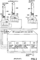
- FIG. 2 shows a typical conventional mobile communications network architecture.
- one BTS cabin 112 is provided per site. Note that only single-sector sites are shown here.
- the BTS cabins 112 are connected to a centralized switching centre 217 of some form. It is this centralized resource which manages the process of rerouting user data packets or voice circuits from one BTS to another when a user is handed over from one site to another as he/she moves within the mobile communications network.
- the mobile switching centre 217 comprises a first transport section 212 to connect the mobile switching centre 217 with the base stations 112 within the base station cabins 110. As mentioned above, this connection is achieved by means of the backhaul network.
- the lines connecting the base stations 112 with the mobile switching centre 217 may he, for example, T1/E1 lines, fibre-optic systems (e.g. SONET, SDH), DSL, terrestrial microwave links, etc.
- connection between the BTS and the switching centre may not be a direct one.
- a radio network controller RNC
- RNC radio network controller
- a base station or typically a number of base stations, referred to as 'Node B's
- 'Node B's base stations
- the principle of a base station connecting (either directly or indirectly) to some form of switching centre or network control centre remains.
- Each of the base stations 112 is connected to an active antenna 205 by means of a fibre-optic cable 108 to/from BTS baseband section and by means of a power supply cable 109.
- the mobile switching centre 217 further comprises a switching/handover module 214 which manages switching and handover control functions when the handling of the mobile station of a user needs to be transferred from one antenna site to another antenna site,
- the handover process involves the transmission of large amounts of data all the way back to this centralized resource, the mobile switching centre 217.
- the mobile switching centre 217 could be hundreds of miles away from the two antenna sites involved in the handover process. These two antenna sites may only be a few hundred metres apart, Accordingly, the handover process is potentially very wasteful of fixed-line transmission bandwidth.
- the mobile switching centre 217 also comprises a power supply unit 215 and associated control functions.
- the mobile switching centre 217 is connected to a public switched telephone network (PSTN) via a transport section 216.
- PSTN public switched telephone network
- FIG 3 shows a base station architecture according to the teachings disclosed herein.
- this architecture several base stations are combined to form a structure known as a "BTS hotel".
- the purpose of the BTS hotel is the ability to enable the remote radio head or the active antenna to be moved further from the remainder of the base station, and thereby to enable the remainder of the base station to be co-located with similar parts of other base stations (for an entire city, for example).
- This BTS hoteling approach involves all of the baseband/control/transport parts of a number of base stations being hosted at the same location (e.g. for ease of maintenance and to save hosting costs).
- each active antenna has its own local power supply unit (PSU) 315.
- PSU local power supply unit
- Known BTS hoteling structures relied on dedicated links between the BTS hotel 310 and an individual one of the active antennas 205 or remote radio head(s) 107 for communicating data between these two units,
- the antenna site may be relatively far away from the BTS hotel 310.
- the BTS hotel 310 could serve an entire city so that some of the antenna sites could be at a distance as much as several tens of kilometres.
- the presence of a dedicated link between the antenna site and the BTS hotel was typically believed to be inevitable due to the transmission delay issues mentioned above. Providing dedicated links over large distances is expensive, especially in cities where streets would have to be dug up.
- the architecture shown in Figure 3 replaces the dedicated links with connections provided by an available communications network, e.g. a public communications network based on optical fibre or DSL.
- an available communications network e.g. a public communications network based on optical fibre or DSL.
- the transmission delay issue can be addressed by technical features which will be explained below.
- Some types of public telecommunications network may have acceptable transmission delays or transmission delays which can be measured and remain constant.
- An old-fashioned circuit-switched telephone network having no digital sections is an example of such a communications network. In some countries, especially in emerging markets, these types of public telephone network may still exist and even be operative. Telephone usage is likely to shift from fixed-line communications to mobile communications. Released resources of the public telecommunications network may then be used for BTS hoteling purposes.
- the base station components hosted in the BTS hotel in Figure 3 are similar, in function, to those of Figure 1 , with the exception that the additional transport section 216 is now required to enable the digital baseband signals to be transported across the public or private communications network.
- a packet-allocationlscheduling/routing system may also be required within the transport module 216 on the left-hand side of the BTS hotel diagram.
- the basic transport mechanism could take a large number of forms, for example: T1/E1 links, IP-based transmission, fibre-optic systems, DSL, terrestrial microwave links, etc.
- IP internet protocol
- the active antenna systems or the remote radio heads would therefore require IP-based connections to the public (or private) telecommunications network to which they are attached.
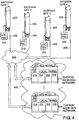
- Figure 4 shows a network architecture similar to that shown in Figure 3 .
- a plurality of BTS hotels 410 is connected to the public or private communications network 350.
- the communications network 350 which may extend over a relatively large geographical area, the assignment of a particular BTS hotel 410 to a particular antenna site is flexible.
- any organisational assignment between BTS hotel 410 and the antenna site may now be resolved, because in principle every BTS hotel of the plurality of BTS hotels attached to the switched network 350 may serve any of the plurality of antenna sites, provided that the BTS hotel has sufficient capacity available.
- Each BTS hotel 410 may be regarded as a shared processing resource. Note that in the architecture of Figure 3 the single BTS hotel 310 may equally be regarded as a shared processing resource.
- processing tasks between the BTS hotels 410 may be shared and distributed according to a packet allocation/scheduling scheme 452.
- the packet allocation/scheduling scheme 452 may be implemented in a self-organizing manner in which each BTS hotel 410 takes over a signal processing task when it has processing resources available.
- one of the BTS hotels 410 acts as an allocation manager.
- each antenna site has a default BTS hotel 410 which performs the signal processing tasks for that antenna site under normal circumstances.
- the default BTS hotel may assign some signal processing tasks to another BTS hotel, for example by forwarding data packets to the other BTS hotel 410, or by instructing the remote radio head 107 and the other BTS hotel 410 to transmit and receive data from each other.
- sharing the baseband and transmission resources in the BTS hotel site(s) may be implemented, such that fewer resources are required overall than would have been provided in total at all of the BTS sites, when using a traditional approach.
- This sharing approach recognizes that the network's resources are effectively never fully utilized across the whole of a network, simultaneously. Given sites may well be fully occupied at given times of the day, but all sites will not be fully used simultaneously at any single point during the day.
- This approach allows the available resources to be accurately tailored to the peaks in demand, based upon the network as a whole, and not on a site-by-site basis. As such, it will save CAPEX (capital expenditure), since fewer resources need to be provided.
- the baseband and network transmission resources are not dedicated to a particular BTS site (antenna site), but act as a central processing resource, dedicating their capabilities to which ever BTS sites (antenna sites) require them at a given moment in time.
- the resources which could be shared include (but are not limited to):
- each site would normally be provided with the following resources in order to meet its forecast peak demand:
- the total resource provided in the mobile communications network would then be:
- the active antenna 205 or the remote radio head 107 does not need to know (and does not care) which of the BTS hotels at different physical locations is supplying the signals the BTS hotel needs to transmit/receive.
- the large "cloud” is, in essence the packet/scheduling/allocation/routing system 452, which determines which BTS baseband card or DSP resource has the required capacity to deal with a particular item or items of traffic, at a given moment in time, This could be a particular BTS site in its entirety, a particular sector at given site, a particular carrier within a given sector or a particular voice or data call on a given carrier.
- the BTS hotel could even change allocations on a packet-by-packed basis; the key element is that this process is entirely transparent to both the BTS site (antenna site) and the cell phone or data-card customers using that site.
- a further aspect of the teaching of the network architectures of Figures 3 and 4 is the ability of the communications network to prioritize the data packets being transmitted, based upon pre-determined criteria (such as the type of service they represent, e.g. video conferencing versus e-mail, or the class of customer, e.g. high-paying corporate client versus private user).
- Information encoded into a packet header or other known part of the data packet can be used to distinguish an originator (or originator classification, e.g. platinum service client versus bronze service client) of the data packet and the type of service subscribed for (e.g. video conferencing versus e-mail).
- the BTS hotel 310, 410 can prioritize the data packets the BTS hotel 310, 410 processes (and the packets the BTS hotel 310, 410 sends to the BTS/antenna sites) to provide a higher grade of service to users who have paid for the higher grade of service.
- the users who have only paid for a low grade of service may experience a slower throughput rate or even a loss of connection in particularly busy periods.
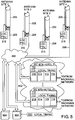
- FIG. 5 shows another possible network architecture similar to the one shown in Figure 4 .
- the additional shared processing resources 504 may offer supplementary processing capacity for handling peak demand periods of the mobile communications network.
- An optional local timing module 513 may be connected to the additional shared processing resource(s) 504, although not illustrated as such in Figure 5 , the additional shared processing resources may be part of a computing cloud, such as the packet/allocatlon/seheduling/routhig system 452, or be part of a cloud computing environment.
- the baseband modules of the BTS hotels 410 may be trimmed down baseband sections 514, in terms of processing power and compared to architectures where no additional shared processing resources 504 are available.
- the additional shared processing resources 504 might be used for time-insensitive processing tasks, such as compiling usage data for billing purposes or the like.
- FIG. 6 shows a schematic block diagram of an active antenna array 205 according to the teachings disclosed herein.
- the active antenna 205 is configured as an active antenna array having a plurality of antenna elements 608 and a plurality of transceiver paths.
- One transceiver path of the plurality of transceiver paths usually corresponds to, and is connected to, one of the plurality of antenna elements 608.
- Each of the transceiver paths comprises a duplex filter 607 for separating transmit signals from receive signals in the frequency domain (frequency division duplex, FDD). Other types of duplexing techniques may be used, in which case the duplex filter 607 may be replaced by a suitable element.
- the antenna element 608 is connected to one side of the duplex filter 607.
- a transmit path and a receive path are connected to the duplex filter 607.
- the receive path is the lower path and will be described first.
- the receive signals picked up by the antenna element 608 and filtered by the duplex filter 607 are fed to a low noise amplifier (LNA) 609.
- LNA low noise amplifier
- An amplified receive signal is then digitized in an analogue-to-digital converter 610.
- frequency down-converter 611 frequency down-conversion is then performed on a digitized receive signal generated by the analogue-to-digital converter 610.
- a down-converted receive signal is then forwarded to a transport section 601 of the active antenna 205 or to an optional beamforming module 602.
- the down-converted receive signals from all receive paths are gathered to be sent over the switched network 350 to one of the BTS hotels 310,410, for example.
- the transmit direction (downlink) data communication comprising carrier data is received via the switched network 350 at the transport section 601.
- the carrier data may either be forwarded directly to the transmit paths of the plurality of transceive paths, or they may first be processed in the beamforming module 602 in which they are distributed to the plurality of transmit paths.
- the transmit signals are frequency up-converted in a frequency up-converter 604, digital-to-analogue-converted in a digital-to-analogue-converter 605, and amplified in an amplifier 606.
- the amplifier 606 is typically a power amplifier.
- the amplified transmit signal is fed to the duplex filter 607 to be transmitted by means of the antenna element 608.
- transmit and receive processing architectures assume the use of delta-sigma or other analogue to digital and digital to analogue converters which are capable of converting to or from the radio frequency carrier frequency directly.
- Alternative architectures, which utilise analogue up and down conversion in addition to, or in place of, digital up and downconversion are known in the art and may also be used in active antenna transmitter and receiver systems.
- the antenna array One of the interests of using an antenna array is the antenna array's capability to provide bean-iforming of the electromagnetic field radiated by the antenna.
- the concept of beamforming also works in the receive direction. In the receive direction, it is the antenna's sensitivity which can be made directional by means of the beamforming technique.
- the beamforming works by slightly modifying the transmit signals applied to the plurality of antenna elements 608 from one antenna element to an adjacent antenna element in phase and/or amplitude. In other words, the transmit signals applied to the various ones of the antenna elements 608 are substantially the same, but slightly shifted with respect to the phase and/or scaled with respect to the amplitude.
- the transmit signals for the plurality of transmit paths can be easily deduced from a master transmit signal, This is done in the beamforming module 602.
- the beamforming module 602 copies the carrier data received from the transport section 601 for each of the plurality of transmit paths. It then applies a plurality of individual phase shifts to the plurality of transmit signals. It may also scale the plurality of transmit signals in order to adjust the amplitudes of the plurality of transmit signals.
- Beamforming can be provided at baseband, IF or RF - it is typically performed at baseband on the already-modulated and combined carrier spectrum, just prior to (digital) upconversion and D/A conversion (or D/A conversion followed by I/Q analogue upconversion).
- the BTS hotel(s) 310, 410 determine(s) beamforming vectors which are sent to the active antenna 205 via the switched network 350 and are utilized by the beamforming module 602,
- a purpose of performing the beamforming at the antenna site is the reduction of data that needs to be transmitted via the communications network 350.
- a reduction by a factor of 16 can be achieved, in theory.
- the real reduction is likely to be slightly less ideal due to the overhead of the transmission of the beamforming vectors and/or the receive signal relationships over the communications network 350.
- FIG. 7 shows a schematic flow chart of a method according to the teachings disclosed herein.
- the radio signals are transceived at block 702.
- the term “transceiving” is intended to describe transmission, reception, or both of radio signals.
- the data packets are passed between the radio heads and non-dedicated processing resources.
- non-dedicated as used herein means that the processing resource is not assigned to a particular one of the radio heads in a fixed manner.
- the term “radio head” also includes active antennas.
- a share of the non-dedicated processing resource(s) is/are allocated ad hoc, on demand at 704. Accordingly, a specific share of the non-dedicated processing resources may perform signal processing tasks or other tasks for a first antenna site during a first period of time, and for a second antenna site at a second period of time. Allocation of the shares of the non-dedicated processing resources is flexible and one of the few conditions that have to be met is that sufficient processing power is available in total to be able to handle peak processing demands averaged across all of the BTS sites ascribed, to a particular BTS hotel or set of interconnected BTS hotels.
- the transceived radio signals are processed in the allocated share of the non-dedicated processing resource.
- processing typically includes the generation of carrier data on the basis of user baseband signals (e.g. voice signals).
- user baseband signals e.g. voice signals
- scrambling or spectrum spreading is performed at this stage to make the transmission of data to the mobile station more reliable and/or secure. Note that for the transmission case the order of the actions typically is different from that shown in Figure 7 .
- the order could be: action 704 (allocation of share of non-dedicated processing resource), action 705 (processing of the signal to be transmitted in the allocated share of the processing resource), action 703 (passing the created data packets to the radio head or the active antenna), and then action 702 (transmission of the radio signals).
- signal processing at 705 typically comprises descrambling the receive signals and converting them to user data packets.
- FIG 8 shows a mixture of a block diagram and a processing diagram for a share of the non-dedicated processing resource(s) 801.
- the transmit or downlink case is first considered.
- User data 802 as provided via the backhaul network is processed by a packet processor 803.
- the packet processor 803 converts the user data 802, which may already be present in the form of data packets, to data packets of antenna-carrier data 804. These data packets are provided to an IP formation unit 807.
- the IP formation unit 807 inserts the antenna-carrier data (packet) 804 into an IP packet 808.
- An IP address for the IP packet 808 is provided by a transceiver selector 805.
- An IP interface 809 transmits the IP packet 808 over the switched network 350 to the antenna site having the IP address selected by the transceiver selector 805.
- the handover from one BTS site to another BTS site is achieved by re-routing of the user data from one cell site to another cell site, using some form of switching centre. This necessitates a large amount of data flowing to and from this cell site, making its OPEX high.
- the structure illustrated in Figure 8 makes possible an alternative handover process.
- the antenna-carrier data may be re-routed from one active antenna site ("BTS") to another at a packet level (e.g. using IP), rather than requiring the intervention of the mobile switching centre or equivalent (there are typically only 3 or 4 mobile switching centres per operator and country).
- the handover is initiated by the mobile station, i.e. the handset of the user.
- the mobile station compares the signal quality of the radio signals the mobile station receives from mobile communications antennas in its vicinity.
- the mobile station checks whether better signal quality could be achieved by having the radio communication transferred to another one of the antenna sites, i.e. the new antenna site.
- the mobile station may then send a handover request and any necessary handover data to the mobile communications network, for example using special handover request data packets sent over a signalling channel of the communication between the mobile station and the antenna site.
- the switching centre could receive the signal quality information from the handset, for the present site and the new site, and instruct the network to perform a hand-over. These handover request data packets may be detected by the packet processor 803.
- the packet processor 803 extracts the handover request and/or the handover data and forwards the handover request and/or the handover data to the transceiver selector 805.
- the transceiver selector 805 may then identify the new antenna site that the mobile station has chosen and determine the antenna site's IP address, for example by querying a data base or a look-up table.
- a short example will illustrate the proposed handover process.
- the mobile station is in radio link communication with antenna site 1.
- the mobile station has detected over a certain period of time (e.g. a number of seconds or minutes) that the antenna site 2 appears to offer better signal quality than the antenna site 1.
- the mobile station then initiates the handover request by sending the handover request data packet to antenna site 1.
- the handover request data packet includes an identification number (ID) of antenna site 2.
- the handover request data packet is forwarded by the antenna site 1 via the switched network 350 to the shared processing resource 801.
- the handover request data packet undergoes normal packet handling in IP Interface 809 and IP formation unit 807 (in this case acting as an IP extraction unit).
- the packet processor 803 extracts the handover information from the data packet.
- the transceiver selector 805 changes a status of the communication with the requesting mobile station by modifying the antenna site preferred by the mobile station as specified in the handover request data packet. Accordingly, the transceiver selector 805 will start to insert an IP address 2 into the IP packets 808 that belong to the communication with the requesting mobile station. This state will prevail until the communication is terminated or the mobile station requests a further handover. In this manner, a large number of the handovers can be handled directly by the shared non-dedicated processing resource(s) 801. Only in situations in which the user completely leaves the coverage area served by the shared non-dedicated processing resource(s) 801, it will be necessary to involve the mobile switching centre 217 (see Figure 2 ).
- the handover may be initiated not by the mobile station but by another component of the mobile communications network.
- the basic idea how a handover request is being processed would still be similar.
- FIG. 9 shows a schematic flow chart of a method for the handover handled by the BTS hotel(s) 310, 410 and/or the shared non-dedicated processing resource(s) 801 themselves,
- the user data packets are processed to form antenna-carricy packets at 902.
- a chosen remotely located transceiver is selected as specified by the mobile station in an initial request for establishing communications or in a most recent handover request.
- the antenna-carrier packets are inserted in the IP packets having the IP address of the chosen remotely located transceiver, at 904. These IP packets are then transmitted over the IP network 350 at 905.
- the method ends at 906 and may be repeated for new user data packets.
- Figure 9 illustrates the downlink case.
- the process is simpler, because the IP address of the IP packets transmitted via the IP network 350 does not depend on the handover request issued by the mobile station.
- the chosen remotely located transceiver for example the active antenna 205 at antenna site 1 knows from information embedded into the receive signal that it is in charge of forwarding the receive signal to the shared non-dedicated processing resource 801. Likewise, the active antenna 205 at the antenna site 2 will ignore these receive signals and will not forward the receive signals, because the receive signals sent over from the mobile station do not address the antenna site 2.
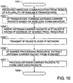
- FIG. 10 shows a schematic flowchart for a method of performing signal processing tasks at shared processing resources for the receive direction, i.e. the uplink direction.
- wireless communication from a mobile station is received at a plurality of available transceivers, as shown in block 1002.
- the mobile station will often be in a position to establish wireless communication with several base stations, especially in urban areas.
- the mobile station and the base stations are operating under, the mobile station will typically choose one of the plurality of base stations.
- the chosen base station will detect that it is in charge of handling the forwarding of the wireless communication and perform the necessary actions, as will be described below.
- the other base stations will only perform a first part of the processing of the wireless communication until they are capable of extracting enough information from the wireless communication to determine that they may ignore the wireless communication in question.
- antenna-carrier packets based on the wireless communication are formed (block 1003), In a subsequent action 1004, the antenna-carrier packets are inserted in the IP packets having the IP address of a shared processing resource.
- the IP address may be pre-determined, for example in a configuration file for the antenna site.
- the shared processing resource with the pre-determined IP address acts as a default processing resource for this antenna site.
- the default processing resource may perform any required data processing itself or it may forward the IP packets to another shared processing resource if the default processing resource is operating close to its capacity limit at this time.
- the IP packets are transmitted over the IP network. Due to the IP address, the IP network routes the IP packets to the shared processing resource having the IP address.
- IP network Due to the IP address, the IP network routes the IP packets to the shared processing resource having the IP address.
- the use of an IP network is an example only to illustrate the ideas disclosed herein.
- the antenna-carrier packets are extracted from the IP packets (block 1006).
- the antenna-carrier packets are processed to form user data packets. The method ends at 1008.
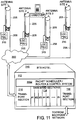
- FIG 11 shows the use of a packet-switchlng/scheduling/rouling module 1152, within the BTS hotel 310, to enable the baseband handover process to operate.
- This module 1152 routes the incoming data packets to the relevant (free) shared baseband resource and, once the incoming data packets have been processed (i.e. converted into a modulated antenna-carrier signal), the shared baseband resource then routes the antenna-carrier packet to the relevant cell-site active antenna (or remote radio head, RRH).
- the active antenna/RRH has an IP-based (or similar) digital input capability, along with suitable packet buffering and a process to convert the packet information into a continuous antenna-carrier data stream for transmission by the active antenna or RRH,
- the BTS hotel 310 shown in Figure 11 comprises a plurality of n baseband sections 1114, These baseband sections 1114 may be freely assigned to the antenna sites, four of which are illustrated in Figure 11 , Assignment of one of the plurality of baseband sections 1114 may be ad hoc and/or on demand, based on the workload of the baseband sections 1114. Certain aspects of the assignment of the plurality of baseband sections 1114 may be controlled by the packet scheduler/router and control system 1152.
- the mobile station that is first in wireless communication with the antenna site 2 may be handed over to the antenna site 3 in a simple manner.
- the BTS hotel 310 it does not make much of a difference whether the data packets belonging to the wireless communication between the mobile station and the antenna site 2, or later the antenna site 3, are forwarded by the antenna site 2 or the antenna site 3,
- the BTS hotel 310 and the packet scheduler/router and control system 1152 may simply look at a user identification with which the data packets are tagged, such as the identification provided by a SIM card.
- the packet scheduler/router and control system 1152 may keep the data processing tasks with the baseband section 1114 that was in charge prior to the handover.
- the antenna site 2 and the antenna site 3 As far as the antenna sites are concerned that are involved in the handover process (the antenna site 2 and the antenna site 3), superfluous network traffic in the switched network 350 can be avoided if that antenna site, which is not currently chosen by the mobile station, does not forward the data packets to the BTS hotel 310, In Figure 11 , the antenna site 2 is in charge prior to the initiation of the handover process and the antenna site 3 is in charge after the handover.
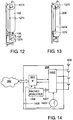
- Figure 12 shows a remote radio head 107 and an antenna 105 that may be used in a network architecture as disclosed herein.
- a local absolute timing reference may be provided, often utilizing a GPS receiver. This provides a very accurate indication of absolute time (typically based on UTC/GMT) and enables the base stations in a network to be accurately synchronized. This is necessary in some CDMA systems, for example, to enable soft-handover to operate correctly.
- This timing information forms the basis for the timing used by the remote radio head, since the BTS rack and the remote radio head are directly connected in known BTS installations.
- BTS holding It would be desirable to be able to move the remote radio head further from the remainder of the BTS, to enable the remainder of the BTS to be co-located with similar parts of other BTSs (for an entire city, for example).
- BTS holding This is known as "BTS holding" and involves all of the baseband/control/trausport parts of a number of base stations being hosted at the same location.
- BTS baseband sections In order to achieve this, however, it would be necessary (with current approaches) to utilize dedicated fibre-optic links from the BTS baseband sections to their respective RKHs. This would be prohibitively expensive in most circumstances.
- the use of existing fibre-optic networks is not an option, since they employ switching and routing systems that introduce a degree of uncertainty into the end-to-end timing.
- the way to overcome this problem is to provide a low-cost, high-accuracy timing reference at the remote radio head end of the system.
- the high-accuracy timing reference is provided as an integral part of the RRH or the active antenna itself
- the high-accuracy timing reference needs to be both stable and provide direct indication of UTC (or some other absolute time reference).
- the use of Caesium atomic clocks, which are typically deployed elsewhere in the mobile communications network, is not an option due to their extremely high cost and also their size/weight.
- a better, low-cost option is to utilize a GPS-based clock.
- a GPS receiver 1273 is mounted on the top of the antenna 105.
- a GPS receiver cable 1274 connects the GPS antenna 1273 with a GPS receiver 1275.
- Figure 13 shows an active antenna 205 equipped with the GPS antenna 1273, the GPS receiver cable 1274, and the GPS receiver 1275. Reference is made to the previous explanations with respect to Figure 12 .
- the remote radio head 107 and the active antenna 205 may now time-synchronize the transmission and/or the reception of wireless communication with the mobile stations. This may be achieved by time-stamping the packets relayed by the remote radio head 107 or the active antenna 205.
- the baseband section 114, 514, 1114 will take the value provided by the absolute timing reference into account to determine the true cell radius measured from the antenna site.
- the form of transport within the switched network 350 is, up to a certain extent, transparent to the BTS system.
- the BTS system no longer has to rely upon timing information that is transmitted back and forth via the link between the BTS system and the remote radio head 107 (or the active antenna 205), since this is now obtained locally by the active antenna 205 or the RRH 107.
- FIG 14 shows a schematic block diagram of an active antenna 205 with integrated absolute timing reference, 1405.
- the active antenna 205 comprises a transmit/receive module 1402 that is connected to a plurality of antenna elements 608.
- the transmit/receive module 1402 is adapted to time-synchronize the transmission of certain portions of the transmit signal belonging to the wireless communication.
- the transmit/receive module 1402 is connected to the absolute timing reference 1405 and also to a packet analyzer 1406.
- the packet analyzer receives packets from the network interface 601 that the active antenna 205 has received from the switched network 350.
- the packet analyzer 1406 extracts a timing information from the packets and forwards it to the transmit/receive module 1402.
- the functionality of the packet analyzer 1406 could be included in the interface 601 or the transmit/receive module 1402.
- the timing information 1407 extracted from the data packets is compared with the current time provided by the absolute timing reference 1405.
- the transmission of the particular portion of the transmit signal is initiated when the current time substantially matches the timing information 1407.
- the base station 112 or the BTS hotel 310, 410 can rely on the transmission of the mentioned portion of the transmit signal to happen at a certain, pre-determined time, under normal circumstances.
- a warning or an error message can be sent to the base station or the BTS hotel if the transmission delay introduced by the switched network 350 is too large so that the transmission at the pre-determined time would no longer be possible.
- the active antenna 205 does not have control over when a certain portion of the receive signal is actually received at its antenna elements 608.
- the data packet containing receive signal information may comprise the time of reception.
- the time of reception may then be evaluated by the base station 112 or the BTS hotel 310, 410.
- the absolute timing reference 1405 sends receive timing information 1408 to the interface 601 to be included in the packets which are to be sent to the base station or the BTS hotel via the switched network 350.
- Figure 15 shows a schematic flowchart of a method for time-synchronized transmission.
- the data packet (or several ones of the data packets) is received at the remote radio head or the active antenna system from an asynchronous network such as the switched network 350 (at 1502).
- the data packet is processed, at 1503, to form the transmit signal,
- an absolute timing reference is determined by means of an absolute timing reference source.
- the transmit signal is transmitted in a time-synchronised manner, for example exactly at a pre-determined time specified in the data packet (within the accuracy of the absolute timing reference source).
- Figure 16 shows a schematic flowchart of a method for the receive direction.
- an absolute timing reference is determined by means of the absolute timing reference source, at 1602.
- the receive signal is received in a time-synchronized manner. Typically this means that the time at which the receive signal was actually received is recorded for subsequent use.
- the receive signal is being processed to form a data packet (or several data packets).
- the receive signal is transmitted over an asynchronous network.
- the method ends at 1605.
- the detrimental influence of an uncertain delay introduced by the switched network 350 is remedied by providing for a time-synchronized transmission and/or reception at the antenna site itself. This is made possible by the antenna site comprising, or having access to, an absolute timing reference with the required precision. This works as long as the transmission delay introduced by the switched network 350 is not too large.
- the proposed solution makes the link between the base station 112 or the BTS hotel 310, 410 and the antenna site transparent. Note that any timing information provided by the base station 112 or the BTS hotel 310, 410 for the purposes of the mobile station may need to be modified by the antenna site to insert the actual transmission/reception time,
- FIG 17 shows the basic elements required in an IP-based (or other packet-based) RRH or active antenna system.
- a CPRI or OBSAI synchronous interface has been replaced by an IP or DSL (or similar) physical layer and a packet processing subsystem, the detailed operation of which is summarized in Figure 18 .
- the baseband processing elements including (where relevant) digital up-conversion, crest factor reduction, beamforming processing, digital pre-distortion and A/D and D/A conversion, remain unchanged from existing RRH or active antenna system designs.
- the RRH comprises a physical layer interface 1701 for IP or DSL which connects the RRH or the active antenna with the public communications network.
- a protocol stack 1702 is connected to the physical layer interface 1701.
- Digital processing for the purposes of crest factor reduction (CFR), digital pre-distortion (DPD), or other purposes is performed in a block 1703.
- a radio frequency electronics module 1704 conditions the transmit signal for transmission to the mobile station. In the other direction the radio frequency electronics module 1704 conditions signals received from the mobile station for subsequent digital processing within the digital processing block 1703.
- Figure 18 provides an example breakdown of the functionality required in the new packet-based digital input to the active antenna system or the remote radio head.
- the flowchart shown in Figure 18 is valid for the transmit direction.
- a corresponding flowchart for the receive direction may be easily derived from the teachings disclosed herein.
- packet data is received from the public communications network.
- the raw data is extracted from the transmission medium (e.g. fibre optic or copper cable) by means of physical layer processing.
- the data packets are then ordered, for example based upon a header time-stamp, at 1802.
- the ordered data packets are fed into a local FIFO buffer.
- Step 1802 reads from the input buffer and orders the data packets, based upon the time-stamp or other header sequencing information, before placing them (in the correct sequence) in the main FIFO buffer (step 1803).
- the data packets are then read from the buffer (step 1804) at the required rate to (ultimately) provide a continuous antenna-carrier data string, at the correct bit-rate, to feed the RRH's or the active antenna system's digital processing circuitry.
- step 1805 the overhead information (packet headers, preamble information, etc.) is removed from the data packets to leave the wanted payload data.
- This payload data is then placed "end-to-end" (step 1806) to form a continuous data stream of the antenna-carrier data.
- this continuous data stream is forwarded to the active antenna system's or the remote radio head's baseband processing circuit (step 1807). From this point onwards in the system, the data is treated in exactly the same way as equivalent data which would have arrived, in an existing implementation, via CPRI or OBSAI (or similar).
- the order of some of the steps may be altered, without loss of functionality. For example, it is possible to strip the overhead (e.g. preamble and header) information from the data packets, prior to loading them into the FIFO stack/buffer.
- the entries in this buffer now consist purely of small parts of the wanted antenna-carrier data (plus any embedded control data etc. - a separate step, not shown in the diagram, would form this control data into a separate data stream to be fed separately to the digital subsystem).
- Such control data is typically not time sensitive (within reasonable bounds) and is generally at a low data rate.
- the antenna-carrier data stream is now formed directly from placing the antenna-carrier information, extracted from the buffer "end-to-end", to form a continuous stream of data.
- the invention also includes mechanisms to:
- Such software can enable, for example, the function, fabrication, modelling, simulation, description and/or testing of the apparatus and methods describe herein. For example, this can be accomplished through the use of general program languages (e.g., C, C++), hardware description languages (HDL) including Verilog HDL, VHDL, and so on, or other available programs.
- Such software can be disposed in any known non-transitory computer useable medium such as semiconductor, magnetic disc, or optical disc (e.g., CD-ROM, DVD-ROM, etc.).
- the software can also be disposed as computer data embodied in a non-transitory computer useable (e.g.
- Embodiments of the present invention may include methods of providing the apparatus described herein by providing software describing the apparatus and subsequently transmitting the software as a computer data signal over a communication network including the internet and intranets.
- the apparatus and method described herein may be included in a semiconductor intellectual property core, such as a micro processor core (e.g., embodied in HDL) and transformed to hardware in the production of integrated circuits. Additionally, the apparatus and methods described herein may be embodied as a combination of hardware and software. Thus, the present invention should not be limited by any of the above-described exemplary embodiments, but should be defined only in accordance with the following claims.
Landscapes
- Engineering & Computer Science (AREA)
- Computer Networks & Wireless Communication (AREA)
- Signal Processing (AREA)
- Mobile Radio Communication Systems (AREA)
Claims (14)
- Mobilfunknetz, umfassend:eine Vielzahl von Funkköpfen (107, 205), die ausgelegt sind, um Funksignale zu senden/empfangen und um die Funksignale zwischen Basisbanddarstellungen der Funksignale und Radiofrequenzdarstellung der Funksignale umzuwandeln, umfassend:eine Verarbeitungsarchitektur (112, 310, 350, 410, 452, 504), die ausgelegt ist, um die Basisbanddarstellungen der Funksignale zu verarbeiten und die ausgelegt ist, um sie ad-hoc zwischen verschiedenen der Vielzahl von Funkköpfen (107, 205) zuzuteilen und auf Abruf zuteilen; wobeidie Verarbeitungsarchitektur eine Cloud-Verarbeitungsarchitektur ist und nichtdedizierte Verarbeitungsressourcen (112, 310, 350, 410, 452, 504) umfasst, die ausgelegt sind, um zwischen verschiedenen der Vielzahl von Funkköpfen (107, 205) geteilt zu werden; undeine Vielzahl von Funkkopfverbindungen zwischen der Vielzahl von Funkköpfen (107, 205) und der Cloud-Verarbeitungsarchitektur,dadurch gekennzeichnet, dassdie Cloud-Verarbeitungsarchitektur, die eine Vielzahl von BTS-Hotels (410) umfasst, die mit einem asynchron geschalteten Netz (350) verbunden sind, wobei ein Funkkopf eine aktive Antenne (205) umfasst, die ein Sende- / Empfangsmodul (1402) umfasst, das mit einer Vielzahl von Antennenelementen (608) verbunden ist,wobei für eine Downlink-Kommunikation von der aktiven Antenne (205) zu einer Mobilstation das Sende- / Empfangsmodul (1402) ausgelegt ist, um die Übertragung von bestimmten Abschnitten des Sendefunksignals zeitlich zu synchronisieren; das Sende- / Empfangsmodul (1402) ist mit einer integrierten absoluten Zeitpunktreferenz (1405) und mit einem Paketanalysator (1406) verbunden, wobei der Paketanalysator (1406) ausgelegt ist, um Pakete von einer Netzschnittstelle (601) zu empfangen, wobei die Pakete von der aktiven Antenne (205) von dem geschalteten Netz (350) empfangen wurden, wobei der Paketanalysator ferner ausgelegt ist, um eine Zeitpunktinformation (1407) aus den empfangenen Paketen zu extrahieren und die Timing-Information (1407) an das Sende- / Empfangsmodul (1402) weiterzuleiten, undwobei die aktive Antenne (205) ausgelegt ist, die Zeitpunktinformationen (1407) mit einer durch die absolute Zeitpunktreferenz (1405) bereitgestellten aktuellen Zeit zu vergleichen, und wobei die aktive Antenne (205) ausgelegt ist, um eine Übertragung des Abschnittes des Sendesignals zu initiieren, wenn die aktuelle Zeit mit der Zeitpunktinformation übereinstimmt (1407).
- Mobilfunknetz nach Anspruch 1, ferner umfassend:eine Basisstation (112, 310, 410); undeine paketbasierte Basisstationsverbindung zwischen der Basisstation (112, 310, 410) und der Cloud-Verarbeitungsarchitektur (112, 310, 350, 410, 452, 504).
- Mobilfunknetz nach einem der vorhergehenden Ansprüche, ferner umfassend:eine Basisstation-Zeitpunktreferenz.
- Mobilfunknetz nach einem der vorhergehenden Ansprüche, ferner umfassend:eine PSTN-Verbindung als ein Teil der Vielzahl von Funkkopfverbindungen.
- Mobilfunknetz nach einem der vorhergehenden Ansprüche, wobei die Vielzahl von Funkköpfen (107, 205) einen Up-Konverter (604) und / oder einen Down-Konverter (611) umfasst, der ausgelegt ist, um die Funksignale frequenzkonvertieren zu können.
- Mobilfunknetz nach einem der vorhergehenden Ansprüche, wobei der Abruf zum Zuteilen eines Anteils der Cloud-Verarbeitungsarchitektur (112, 310, 350, 410, 452, 504) auf einer Anzahl von Benutzern basiert, die mit einem bestimmten Funkkopf (107, 205) verbunden sind und / oder einer Datenmenge, die über den Funkkopf (107, 205) heruntergeladen oder hochgeladen wurde.
- Mobilfunknetz nach einem der vorhergehenden Ansprüche, wobei die Verzögerung entlang der Vielzahl von Funkkopfverbindungen variiert.
- Verfahren zum Verarbeiten von Funksignalen für ein Mobilfunknetz, umfassend:Empfangen/Senden der Funksignale;Umwandeln der Funksignale zwischen Basisbanddarstellungen der Funksignale und Hochfrequenzdarstellungen der Funksignale;Durchleiten von Paketen der Basisbanddarstellungen der Funksignale zwischen einer Vielzahl von Funkköpfen (107, 205) und einer Vielzahl von nicht dedizierten Verarbeitungsressourcen (112, 310, 350, 410, 452, 504);Ad-hoc-Zuteilung bei Bedarf eines Anteils einer nicht dedizierten Verarbeitungsressource (112, 310, 350, 410, 452, 504) aus der Vielzahl von gemeinsam nutzbaren Verarbeitungsressourcen (112, 310, 350, 410, 452) zum Verarbeiten der Basisbanddarstellungen der Funksignale;Verarbeiten der Basisbanddarstellungen der empfangene/gesendeten Funksignale in dem zugewiesenen Anteil der Verarbeitungsressourcen (112, 310, 350, 410, 452, 504) unter Verwendung des lokalen Zeitpunktmoduls (113), wobei die Vielzahl von nicht dedizierten Verarbeitungsressourcen (112, 310, 350, 410, 452, 504) als eine Cloud-Verarbeitungsarchitektur organisiert sind,Durchleiten von Paketen zwischen der Vielzahl von Funkköpfen (107, 205) und der Cloud-Verarbeitungsarchitektur über eine Vielzahl von Funkkopfverbindungen, dadurch gekennzeichnet, dass die Cloud-Verarbeitungsarchitektur mehrere BTS-Hotels (410) umfasst, die mit einem asynchron geschalteten Netz (350) verbunden sind, das Verfahren umfasst:Empfangen, durch eine aktive Antenne (205), von Paketen von dem geschalteten Netz (305),für Downlink-Kommunikationen von der aktiven Antenne (205) zu einer Mobilstation, Zeitsynchronisieren, durch ein Sende- / Empfangsmodul (1402) der aktiven Antenne (205), die Übertragung eines Teils eines Sendefunksignals,wobei die Zeitsynchronisierung das Verbinden des Sende- / Empfangsmoduls (1402) mit einer Vielzahl von Antennenelementen (608) umfasst, wobei das Sende- / Empfangsmodul (1402) an eine integrierte absoluten Zeitpunktreferenz (1405) und an einen Paketanalysator verbunden ist (1406),Empfangen der empfangenen Pakete durch den Paketanalysator, Extrahieren, durch den Paketanalysator, einer Zeitpunktinformation (1407) aus den empfangenen Paketen und Weiterleiten der Zeitpunktinformation an das Sende- / Empfangsmodul (1402),Vergleichen der Zeitpunktinformation (1407) mit einer aktuellen Zeit, die durch die absolute Zeitpunktreferenz (1405) bereitgestellt wird,Initiieren der Übertragung des Teils des Sendefunksignals, wenn die aktuelle Zeit mit der Zeitpunktinformation (1407) übereinstimmt.
- Verfahren nach Anspruch 8, ferner umfassend das Weiterleiten von Paketen von basisstationsbezogenen Daten zwischen einer Basisstation (112, 310, 410) und der Vielzahl von nicht dedizierten Verarbeitungsressourcen (112, 310, 350, 410, 452, 504) über eine paketbasierte Basisstationsverbindung.
- Verfahren nach einem der Ansprüche 8 oder 9, ferner umfassend:Bereitstellen einer Basisstationszeitpunktreferenz lokal an eine Basisstation (112, 310, 410), die Teil des Mobilfunknetzes ist.
- Das Verfahren nach einem der Ansprüche 8 bis 10, weiter umfassend Frequenzumwandeln der Funksignale an einem Funkkopf der Vielzahl von entfernten Funkköpfen (107, 205).
- Verfahren nach einem der Ansprüche 8 bis 11, wobei der Abruf zum Zuteilen eines Anteils der Cloud-Verarbeitungsarchitektur (112, 310, 350, 410, 452, 504) auf einer Anzahl von Benutzern basiert, die mit einem bestimmten Funkkopf (107, 205) verbunden sind.
- Verfahren nach einem der Ansprüche 8 bis 12, wobei der Abruf zum Zuteilen eines Anteils der Cloud-Verarbeitungsarchitektur (112, 310, 350, 410, 452, 504) auf einer Datenmenge beruht, die über den Funkkopf (107, 205) heruntergeladen oder hochgeladen wird.
- Computerprogrammprodukt, das ein nichtflüchtiges computerverwendbares Medium mit einer darin gespeicherten Steuerlogik zum Veranlassen eines Mobilfunknetzes zum Ausführen eines Verfahrens zum Verarbeiten von Basisbanddarstellungen von Funksignalen für ein Mobilfunknetzt, umfassend:Empfangen/Senden der Funksignale;Umwandeln der Funksignale zwischen Basisbanddarstellungen der Funksignale und Hochfrequenzdarstellungen der Funksignale;Durchleiten von Paketen der Basisbanddarstellungen der Funksignale zwischen einer Vielzahl von Funkköpfen (107, 205) und einer Vielzahl von nicht dedizierten Verarbeitungsressourcen (112, 310, 350, 410, 452, 504);Ad-hoc-Zuteilung bei Bedarf eines Anteils einer nicht dedizierten Verarbeitungsressource (112, 310, 350, 410, 452, 504) aus der Vielzahl von gemeinsam nutzbaren Verarbeitungsressourcen (112, 310, 350, 410, 452) zum Verarbeiten der Basisbanddarstellungen der Funksignale;Verarbeiten der Basisbanddarstellungen der empfangene/gesendeten Funksignale in dem zugewiesenen Anteil der Verarbeitungsressourcen (112, 310, 350, 410, 452, 504) unter Verwendung des lokalen Zeitpunktmoduls (113), wobei die Vielzahl von nicht dedizierten Verarbeitungsressourcen (112, 310, 350, 410, 452, 504) als eine Cloud-Verarbeitungsarchitektur organisiert sind,Durchleiten von Paketen zwischen der Vielzahl von Funkköpfen (107, 205) und der Cloud-Verarbeitungsarchitektur über eine Vielzahl von Funkkopfverbindungen, dadurch gekennzeichnet, dass die Cloud-Verarbeitungsarchitektur mehrere BTS-Hotels (410) umfasst, die mit einem asynchron geschalteten Netz (350) verbunden sind, das Verfahren umfasst:Empfangen, durch eine aktive Antenne (205), von Paketen von dem geschalteten Netz (305),für Downlink-Kommunikationen von der aktiven Antenne (205) zu einer Mobilstation, Zeitsynchronisieren, durch ein Sende- / Empfangsmodul (1402) der aktiven Antenne (205), die Übertragung eines Teils eines Sendefunksignals,wobei die Zeitsynchronisierung das Verbinden des Sende- / Empfangsmoduls (1402) mit einer Vielzahl von Antennenelementen (608) umfasst, wobei das Sende- / Empfangsmodul (1402) an eine integrierte absoluten Zeitpunktreferenz (1405) und an einen Paketanalysator verbunden ist (1406),Empfangen der empfangenen Pakete durch den Paketanalysator, Extrahieren, durch den Paketanalysator, einer Zeitpunktinformation (1407) aus den empfangenen Paketen und Weiterleiten der Zeitpunktinformation an das Sende- / Empfangsmodul (1402),Vergleichen der Zeitpunktinformation (1407) mit einer aktuellen Zeit, die durch die absolute Zeitpunktreferenz (1405) bereitgestellt wird,Initiieren der Übertragung des Teils des Sendefunksignals, wenn die aktuelle Zeit mit der Zeitpunktinformation (1407) übereinstimmt.
Applications Claiming Priority (2)
| Application Number | Priority Date | Filing Date | Title |
|---|---|---|---|
| US12/817,871 US8774109B2 (en) | 2010-06-17 | 2010-06-17 | Mobile communications network with distributed processing resources |
| PCT/EP2011/058534 WO2011157519A1 (en) | 2010-06-17 | 2011-05-25 | Mobile communications network with distributed processing resources |
Publications (2)
| Publication Number | Publication Date |
|---|---|
| EP2583531A1 EP2583531A1 (de) | 2013-04-24 |
| EP2583531B1 true EP2583531B1 (de) | 2018-02-28 |
Family
ID=44343918
Family Applications (1)
| Application Number | Title | Priority Date | Filing Date |
|---|---|---|---|
| EP11724390.7A Active EP2583531B1 (de) | 2010-06-17 | 2011-05-25 | Mobiles kommunikationsnetz mit verteilten verarbeitungsressourcen |
Country Status (3)
| Country | Link |
|---|---|
| US (1) | US8774109B2 (de) |
| EP (1) | EP2583531B1 (de) |
| WO (1) | WO2011157519A1 (de) |
Families Citing this family (23)
| Publication number | Priority date | Publication date | Assignee | Title |
|---|---|---|---|---|
| CN104202279A (zh) | 2006-12-26 | 2014-12-10 | 大力系统有限公司 | 用于多信道宽带通信系统中的基带预失真线性化的方法和系统 |
| KR20180026793A (ko) * | 2010-08-17 | 2018-03-13 | 달리 시스템즈 씨오. 엘티디. | 분산 안테나 시스템을 위한 뉴트럴 호스트 아키텍처 |
| CN105141513B (zh) | 2010-09-14 | 2018-12-14 | 大力系统有限公司 | 操作分布式天线系统的方法和在该系统中进行通信的方法 |
| EP2512202B1 (de) * | 2011-04-12 | 2013-11-20 | Alcatel Lucent | Belastungsausgleich in Funkzugriffsnetzwerk |
| WO2013119153A1 (en) * | 2012-02-09 | 2013-08-15 | Telefonaktiebolaget Lm Ericsson (Publ) | A network node and a method therein enabling a first unit to connect or to be connected ad-hoc to a second unit |
| FR2990315B1 (fr) * | 2012-05-04 | 2014-06-13 | Blink E | Procede de transmission d'informations entre une unite emettrice et une unite receptrice |
| EP2670210B1 (de) * | 2012-06-01 | 2014-09-17 | Ntt Docomo, Inc. | System zur Implementierung eines Funks über Faserübertragung in einem passiven optischen Netzwerk |
| EP2944061A4 (de) | 2013-01-14 | 2016-09-07 | Commscope Technologies Llc | Abfängersystem zur charakterisierung von digitalen daten in einem telekommunikationssystem |
| FR3007617A1 (fr) * | 2013-06-19 | 2014-12-26 | France Telecom | Dispositifs de fourniture d'informations de service pour une liaison par faisceau microondes |
| CN106256101B (zh) | 2014-05-08 | 2019-10-25 | 华为技术有限公司 | 用于联合解码的网络设备及其方法 |
| US9699751B2 (en) | 2014-05-14 | 2017-07-04 | Telefonaktiebolaget L M Ericsson (Publ) | Technique for the base station to measure the internal uplink and downlink delays of the node without pre-calibration |
| US9554347B2 (en) | 2014-05-14 | 2017-01-24 | Telefonaktiebolaget L M Ericsson (Publ) | Automatic calibration of processing delay of radio equipment |
| US10405290B2 (en) | 2014-05-14 | 2019-09-03 | Telefonaktiebolaget Lm Ericsson (Publ) | Technique to align frame timing of remote cellular radio elements with the data frame timing reference of radio element |
| US9497760B2 (en) | 2014-11-25 | 2016-11-15 | Telefonaktiebolaget Lm Ericsson (Publ) | Allocating baseband resource capacity to cells based on baseband processing deadline margins |
| US9407383B2 (en) | 2014-12-23 | 2016-08-02 | Ibiquity Digital Corporation | Apparatus and method for distributing content from an HD radio system |
| US9954591B2 (en) * | 2015-01-16 | 2018-04-24 | RF DSP Inc. | Beamforming in a MU-MIMO wireless communication system |
| US10785737B2 (en) | 2015-11-02 | 2020-09-22 | Telefonaktiebolaget Lm Ericsson (Publ) | Technique to align a radio interface frame timing reference in a pool of radio equipment controllers |
| US10771508B2 (en) | 2016-01-19 | 2020-09-08 | Nadejda Sarmova | Systems and methods for establishing a virtual shared experience for media playback |
| US10608919B2 (en) | 2016-02-19 | 2020-03-31 | Commscope Technologies Llc | Passive intermodulation (PIM) testing in distributed base transceiver station architecture |
| US10609582B2 (en) | 2016-09-08 | 2020-03-31 | Commscope Technologies Llc | Interference detection and identification in wireless network from RF or digitized signal |
| WO2018053291A1 (en) * | 2016-09-16 | 2018-03-22 | Altaeros Energies, Inc. | Wireless communication station |
| US10498442B2 (en) * | 2017-08-04 | 2019-12-03 | T-Mobile Usa, Inc. | Wireless delivery of broadcast data |
| CN114390504B (zh) * | 2021-12-31 | 2023-09-15 | 浙江威力克通信股份有限公司 | 一种应急移动通信系统的主体设备 |
Citations (1)
| Publication number | Priority date | Publication date | Assignee | Title |
|---|---|---|---|---|
| US20080181182A1 (en) * | 2007-01-12 | 2008-07-31 | Scott Carichner | Digital radio head system and method |
Family Cites Families (23)
| Publication number | Priority date | Publication date | Assignee | Title |
|---|---|---|---|---|
| JPS62225096A (ja) | 1986-03-26 | 1987-10-03 | Nec Corp | 無線電話方式 |
| WO1997015160A1 (en) | 1995-10-17 | 1997-04-24 | Telefonaktiebolaget Lm Ericsson (Publ) | A method for performing handover and roaming in a radio communication environment |
| JP3586788B2 (ja) | 1999-09-14 | 2004-11-10 | 株式会社日立製作所 | 無線ネットワーク |
| US6751467B1 (en) | 1999-09-15 | 2004-06-15 | Pacific Creit Corporation | System and method for using corrected signals from a global positioning system to perform precision survey |
| EP1085773A1 (de) | 1999-09-20 | 2001-03-21 | Nortel Matra Cellular | Mobilkommunikationsnetz mit verteilten Basisstationen |
| AU2001239934A1 (en) | 2000-04-27 | 2001-11-12 | Lgc Wireless, Inc. | Adaptive capacity management in a centralized basestation architecture |
| US6353600B1 (en) | 2000-04-29 | 2002-03-05 | Lgc Wireless, Inc. | Dynamic sectorization in a CDMA cellular system employing centralized base-station architecture |
| US7493129B1 (en) * | 2002-09-12 | 2009-02-17 | At&T Mobility Ii Llc | Method and apparatus to maintain network coverage when using a transport media to communicate with a remote antenna |
| US7200391B2 (en) | 2002-12-06 | 2007-04-03 | Airvana, Inc. | Capacity enhancement schemes for forward and reverse links of distributed cellular base stations |
| US6785558B1 (en) * | 2002-12-06 | 2004-08-31 | Lgc Wireless, Inc. | System and method for distributing wireless communication signals over metropolitan telecommunication networks |
| KR20040092259A (ko) | 2003-04-25 | 2004-11-03 | 삼성전자주식회사 | 기지국 장치를 위한 위성 클럭 동기 시스템 및 이를이용한 기지국 시스템의 위성 클럭 동기화 방법 |
| US20050157675A1 (en) | 2004-01-16 | 2005-07-21 | Feder Peretz M. | Method and apparatus for cellular communication over data networks |
| US7664534B1 (en) | 2004-06-03 | 2010-02-16 | Sprint Spectrum L.P. | Communications system and method using remote antennas |
| US7583735B2 (en) | 2005-03-31 | 2009-09-01 | Adc Telecommunications, Inc. | Methods and systems for handling underflow and overflow in a software defined radio |
| US20070058742A1 (en) | 2005-09-09 | 2007-03-15 | Demarco Anthony | Distributed antenna system using signal precursors |
| EP2095550B1 (de) | 2006-08-22 | 2018-10-03 | Juniper Networks, Inc. | Vorrichtung und verfahren zum synchronisieren der verteilung von paketdiensten über ein verteiltes netz |
| US8666428B2 (en) | 2008-01-29 | 2014-03-04 | Alcatel Lucent | Method to support user location in in-structure coverage systems |
| US20090262732A1 (en) | 2008-04-16 | 2009-10-22 | Barry Wood | Data Communications Network |
| US8083302B2 (en) | 2008-06-11 | 2011-12-27 | Adc Telecommunications, Inc. | L-shaped doors with trapezoidal seal |
| US9198222B2 (en) | 2008-10-22 | 2015-11-24 | International Business Machines Corporation | Telecommunication network |
| US8612595B2 (en) * | 2009-10-05 | 2013-12-17 | Nokia Corporation | Wireless resource sharing framework |
| US8233408B2 (en) * | 2009-12-10 | 2012-07-31 | Wei Lu | Mobile cloud architecture based on open wireless architecture (OWA) platform |
| US9041765B2 (en) * | 2010-05-12 | 2015-05-26 | Blue Jeans Network | Systems and methods for security and privacy controls for videoconferencing |
-
2010
- 2010-06-17 US US12/817,871 patent/US8774109B2/en active Active
-
2011
- 2011-05-25 EP EP11724390.7A patent/EP2583531B1/de active Active
- 2011-05-25 WO PCT/EP2011/058534 patent/WO2011157519A1/en not_active Ceased
Patent Citations (1)
| Publication number | Priority date | Publication date | Assignee | Title |
|---|---|---|---|---|
| US20080181182A1 (en) * | 2007-01-12 | 2008-07-31 | Scott Carichner | Digital radio head system and method |
Non-Patent Citations (1)
| Title |
|---|
| CHINA MOBILE RESEARCH INSTITUTE: "C-RAN; The road towards Green RAN", INTERNET CITATION, April 2010 (2010-04-01), pages 1 - 31, XP002704051, Retrieved from the Internet <URL:http://nashville.dyndns.org:800/WirelessDownloads/lte/Backhaul%20and%20Transport/50292032-CRAN-white-paper-v1-14.pdf> [retrieved on 20130723] * |
Also Published As
| Publication number | Publication date |
|---|---|
| WO2011157519A1 (en) | 2011-12-22 |
| US20110310810A1 (en) | 2011-12-22 |
| EP2583531A1 (de) | 2013-04-24 |
| US8774109B2 (en) | 2014-07-08 |
Similar Documents
| Publication | Publication Date | Title |
|---|---|---|
| EP2583531B1 (de) | Mobiles kommunikationsnetz mit verteilten verarbeitungsressourcen | |
| US8649354B2 (en) | Handover in mobile communications networks | |
| US20110310941A1 (en) | Remotely located radio transceiver for mobile communications network | |
| US20110310881A1 (en) | Remote radio head | |
| US11368957B2 (en) | Remotely reconfigurable distributed antenna system and methods | |
| Wang et al. | Backhauling 5G small cells: A radio resource management perspective | |
| EP2810379B1 (de) | Optimiertes telekommunikationsverteilsystem | |
| US20190364616A1 (en) | 5G Interoperability Architecture | |
| JP5263786B2 (ja) | 無線通信システム、無線基地局および制御方法 | |
| EP2954716B1 (de) | Funkkommunikationssystem | |
| US20100136932A1 (en) | Method and a radio base station in a telecommunications system | |
| KR20110043769A (ko) | 다운링크를 통해 네트워크-와이드 다중 입력 다중 출력 무선 통신을 지원하는 아키텍처 | |
| Hailu et al. | Mobile fronthaul transport options in C-RAN and emerging research directions: A comprehensive study | |
| Saadani et al. | Digital radio over fiber for LTE-advanced: Opportunities and challenges | |
| EP3922078A1 (de) | Hybride basisstation und rrh | |
| US12382384B2 (en) | OpenRAN solution suite | |
| EP2080293A1 (de) | Rahmenwerk zur konzeption eines neuen mac-nachrichtenaustauschverfahrens in zusammenhang mit einer mobilstationsweiterleitung in einem drahtlosen multihop-relais-breitband-netzwerk | |
| WO2017028933A1 (en) | Radio base station | |
| EP4292393A1 (de) | Hybride daten-über-kabel-dienstschnittstellenspezifikation (docsis) 5g new radio (nr) der fünften generation (5g) | |
| JP5469032B2 (ja) | 無線通信システム、および無線通信装置 | |
| JP7535597B2 (ja) | データ再生インタフェースを有する狭帯域aas受信機 | |
| US20240224205A1 (en) | Time synchronization over cloud radio access networks | |
| Artuso et al. | Cloudification of mmwave-based and packet-based fronthaul for future heterogeneous mobile networks | |
| Chih-Lin et al. | NGFI, the xHaul | |
| KR20160111829A (ko) | 기지국 장비, 자원 관리 방법 및 데이터 처리 방법 |
Legal Events
| Date | Code | Title | Description |
|---|---|---|---|
| PUAI | Public reference made under article 153(3) epc to a published international application that has entered the european phase |
Free format text: ORIGINAL CODE: 0009012 |
|
| 17P | Request for examination filed |
Effective date: 20130117 |
|
| AK | Designated contracting states |
Kind code of ref document: A1 Designated state(s): AL AT BE BG CH CY CZ DE DK EE ES FI FR GB GR HR HU IE IS IT LI LT LU LV MC MK MT NL NO PL PT RO RS SE SI SK SM TR |
|
| DAX | Request for extension of the european patent (deleted) | ||
| RAP1 | Party data changed (applicant data changed or rights of an application transferred) |
Owner name: KATHREIN-WERKE KG |
|
| 17Q | First examination report despatched |
Effective date: 20140918 |
|
| GRAP | Despatch of communication of intention to grant a patent |
Free format text: ORIGINAL CODE: EPIDOSNIGR1 |
|
| INTG | Intention to grant announced |
Effective date: 20170914 |
|
| GRAJ | Information related to disapproval of communication of intention to grant by the applicant or resumption of examination proceedings by the epo deleted |
Free format text: ORIGINAL CODE: EPIDOSDIGR1 |
|
| GRAR | Information related to intention to grant a patent recorded |
Free format text: ORIGINAL CODE: EPIDOSNIGR71 |
|
| GRAS | Grant fee paid |
Free format text: ORIGINAL CODE: EPIDOSNIGR3 |
|
| GRAA | (expected) grant |
Free format text: ORIGINAL CODE: 0009210 |
|
| INTC | Intention to grant announced (deleted) | ||
| AK | Designated contracting states |
Kind code of ref document: B1 Designated state(s): AL AT BE BG CH CY CZ DE DK EE ES FI FR GB GR HR HU IE IS IT LI LT LU LV MC MK MT NL NO PL PT RO RS SE SI SK SM TR |
|
| INTG | Intention to grant announced |
Effective date: 20180123 |
|
| REG | Reference to a national code |
Ref country code: GB Ref legal event code: FG4D Ref country code: CH Ref legal event code: EP |
|
| REG | Reference to a national code |
Ref country code: AT Ref legal event code: REF Ref document number: 975482 Country of ref document: AT Kind code of ref document: T Effective date: 20180315 |
|
| REG | Reference to a national code |
Ref country code: IE Ref legal event code: FG4D |
|
| REG | Reference to a national code |
Ref country code: DE Ref legal event code: R096 Ref document number: 602011046008 Country of ref document: DE |
|
| REG | Reference to a national code |
Ref country code: FR Ref legal event code: PLFP Year of fee payment: 8 |
|
| REG | Reference to a national code |
Ref country code: SE Ref legal event code: TRGR |
|
| REG | Reference to a national code |
Ref country code: NL Ref legal event code: MP Effective date: 20180228 |
|
| REG | Reference to a national code |
Ref country code: LT Ref legal event code: MG4D |
|
| REG | Reference to a national code |
Ref country code: AT Ref legal event code: MK05 Ref document number: 975482 Country of ref document: AT Kind code of ref document: T Effective date: 20180228 |
|
| PG25 | Lapsed in a contracting state [announced via postgrant information from national office to epo] |
Ref country code: NO Free format text: LAPSE BECAUSE OF FAILURE TO SUBMIT A TRANSLATION OF THE DESCRIPTION OR TO PAY THE FEE WITHIN THE PRESCRIBED TIME-LIMIT Effective date: 20180528 Ref country code: HR Free format text: LAPSE BECAUSE OF FAILURE TO SUBMIT A TRANSLATION OF THE DESCRIPTION OR TO PAY THE FEE WITHIN THE PRESCRIBED TIME-LIMIT Effective date: 20180228 Ref country code: ES Free format text: LAPSE BECAUSE OF FAILURE TO SUBMIT A TRANSLATION OF THE DESCRIPTION OR TO PAY THE FEE WITHIN THE PRESCRIBED TIME-LIMIT Effective date: 20180228 Ref country code: CY Free format text: LAPSE BECAUSE OF FAILURE TO SUBMIT A TRANSLATION OF THE DESCRIPTION OR TO PAY THE FEE WITHIN THE PRESCRIBED TIME-LIMIT Effective date: 20180228 Ref country code: LT Free format text: LAPSE BECAUSE OF FAILURE TO SUBMIT A TRANSLATION OF THE DESCRIPTION OR TO PAY THE FEE WITHIN THE PRESCRIBED TIME-LIMIT Effective date: 20180228 Ref country code: NL Free format text: LAPSE BECAUSE OF FAILURE TO SUBMIT A TRANSLATION OF THE DESCRIPTION OR TO PAY THE FEE WITHIN THE PRESCRIBED TIME-LIMIT Effective date: 20180228 |
|
| PG25 | Lapsed in a contracting state [announced via postgrant information from national office to epo] |
Ref country code: GR Free format text: LAPSE BECAUSE OF FAILURE TO SUBMIT A TRANSLATION OF THE DESCRIPTION OR TO PAY THE FEE WITHIN THE PRESCRIBED TIME-LIMIT Effective date: 20180529 Ref country code: BG Free format text: LAPSE BECAUSE OF FAILURE TO SUBMIT A TRANSLATION OF THE DESCRIPTION OR TO PAY THE FEE WITHIN THE PRESCRIBED TIME-LIMIT Effective date: 20180528 Ref country code: LV Free format text: LAPSE BECAUSE OF FAILURE TO SUBMIT A TRANSLATION OF THE DESCRIPTION OR TO PAY THE FEE WITHIN THE PRESCRIBED TIME-LIMIT Effective date: 20180228 Ref country code: RS Free format text: LAPSE BECAUSE OF FAILURE TO SUBMIT A TRANSLATION OF THE DESCRIPTION OR TO PAY THE FEE WITHIN THE PRESCRIBED TIME-LIMIT Effective date: 20180228 Ref country code: AT Free format text: LAPSE BECAUSE OF FAILURE TO SUBMIT A TRANSLATION OF THE DESCRIPTION OR TO PAY THE FEE WITHIN THE PRESCRIBED TIME-LIMIT Effective date: 20180228 |
|
| REG | Reference to a national code |
Ref country code: DE Ref legal event code: R081 Ref document number: 602011046008 Country of ref document: DE Owner name: TELEFONAKTIEBOLAGET LM ERICSSON (PUBL), SE Free format text: FORMER OWNER: KATHREIN-WERKE KG, 83022 ROSENHEIM, DE Ref country code: DE Ref legal event code: R082 Ref document number: 602011046008 Country of ref document: DE Representative=s name: 24IP LAW GROUP SONNENBERG FORTMANN, DE Ref country code: DE Ref legal event code: R081 Ref document number: 602011046008 Country of ref document: DE Owner name: KATHREIN SE, DE Free format text: FORMER OWNER: KATHREIN-WERKE KG, 83022 ROSENHEIM, DE |
|
| PG25 | Lapsed in a contracting state [announced via postgrant information from national office to epo] |
Ref country code: EE Free format text: LAPSE BECAUSE OF FAILURE TO SUBMIT A TRANSLATION OF THE DESCRIPTION OR TO PAY THE FEE WITHIN THE PRESCRIBED TIME-LIMIT Effective date: 20180228 Ref country code: IT Free format text: LAPSE BECAUSE OF FAILURE TO SUBMIT A TRANSLATION OF THE DESCRIPTION OR TO PAY THE FEE WITHIN THE PRESCRIBED TIME-LIMIT Effective date: 20180228 Ref country code: RO Free format text: LAPSE BECAUSE OF FAILURE TO SUBMIT A TRANSLATION OF THE DESCRIPTION OR TO PAY THE FEE WITHIN THE PRESCRIBED TIME-LIMIT Effective date: 20180228 Ref country code: AL Free format text: LAPSE BECAUSE OF FAILURE TO SUBMIT A TRANSLATION OF THE DESCRIPTION OR TO PAY THE FEE WITHIN THE PRESCRIBED TIME-LIMIT Effective date: 20180228 Ref country code: PL Free format text: LAPSE BECAUSE OF FAILURE TO SUBMIT A TRANSLATION OF THE DESCRIPTION OR TO PAY THE FEE WITHIN THE PRESCRIBED TIME-LIMIT Effective date: 20180228 |
|
| REG | Reference to a national code |
Ref country code: DE Ref legal event code: R097 Ref document number: 602011046008 Country of ref document: DE |
|
| PG25 | Lapsed in a contracting state [announced via postgrant information from national office to epo] |
Ref country code: CZ Free format text: LAPSE BECAUSE OF FAILURE TO SUBMIT A TRANSLATION OF THE DESCRIPTION OR TO PAY THE FEE WITHIN THE PRESCRIBED TIME-LIMIT Effective date: 20180228 Ref country code: SK Free format text: LAPSE BECAUSE OF FAILURE TO SUBMIT A TRANSLATION OF THE DESCRIPTION OR TO PAY THE FEE WITHIN THE PRESCRIBED TIME-LIMIT Effective date: 20180228 Ref country code: DK Free format text: LAPSE BECAUSE OF FAILURE TO SUBMIT A TRANSLATION OF THE DESCRIPTION OR TO PAY THE FEE WITHIN THE PRESCRIBED TIME-LIMIT Effective date: 20180228 Ref country code: SM Free format text: LAPSE BECAUSE OF FAILURE TO SUBMIT A TRANSLATION OF THE DESCRIPTION OR TO PAY THE FEE WITHIN THE PRESCRIBED TIME-LIMIT Effective date: 20180228 |
|
| REG | Reference to a national code |
Ref country code: CH Ref legal event code: PL |
|
| PLBE | No opposition filed within time limit |
Free format text: ORIGINAL CODE: 0009261 |
|
| STAA | Information on the status of an ep patent application or granted ep patent |
Free format text: STATUS: NO OPPOSITION FILED WITHIN TIME LIMIT |
|
| RAP2 | Party data changed (patent owner data changed or rights of a patent transferred) |
Owner name: KATHREIN SE |
|
| REG | Reference to a national code |
Ref country code: BE Ref legal event code: MM Effective date: 20180531 |
|
| PG25 | Lapsed in a contracting state [announced via postgrant information from national office to epo] |
Ref country code: MC Free format text: LAPSE BECAUSE OF FAILURE TO SUBMIT A TRANSLATION OF THE DESCRIPTION OR TO PAY THE FEE WITHIN THE PRESCRIBED TIME-LIMIT Effective date: 20180228 |
|
| 26N | No opposition filed |
Effective date: 20181129 |
|
| REG | Reference to a national code |
Ref country code: IE Ref legal event code: MM4A |
|
| PG25 | Lapsed in a contracting state [announced via postgrant information from national office to epo] |
Ref country code: SI Free format text: LAPSE BECAUSE OF FAILURE TO SUBMIT A TRANSLATION OF THE DESCRIPTION OR TO PAY THE FEE WITHIN THE PRESCRIBED TIME-LIMIT Effective date: 20180228 Ref country code: LI Free format text: LAPSE BECAUSE OF NON-PAYMENT OF DUE FEES Effective date: 20180531 Ref country code: CH Free format text: LAPSE BECAUSE OF NON-PAYMENT OF DUE FEES Effective date: 20180531 |
|
| PG25 | Lapsed in a contracting state [announced via postgrant information from national office to epo] |
Ref country code: LU Free format text: LAPSE BECAUSE OF NON-PAYMENT OF DUE FEES Effective date: 20180525 |
|
| REG | Reference to a national code |
Ref country code: GB Ref legal event code: 732E Free format text: REGISTERED BETWEEN 20190314 AND 20190320 |
|
| PG25 | Lapsed in a contracting state [announced via postgrant information from national office to epo] |
Ref country code: IE Free format text: LAPSE BECAUSE OF NON-PAYMENT OF DUE FEES Effective date: 20180525 |
|
| PG25 | Lapsed in a contracting state [announced via postgrant information from national office to epo] |
Ref country code: BE Free format text: LAPSE BECAUSE OF NON-PAYMENT OF DUE FEES Effective date: 20180531 |
|
| PG25 | Lapsed in a contracting state [announced via postgrant information from national office to epo] |
Ref country code: MT Free format text: LAPSE BECAUSE OF NON-PAYMENT OF DUE FEES Effective date: 20180525 |
|
| PG25 | Lapsed in a contracting state [announced via postgrant information from national office to epo] |
Ref country code: TR Free format text: LAPSE BECAUSE OF FAILURE TO SUBMIT A TRANSLATION OF THE DESCRIPTION OR TO PAY THE FEE WITHIN THE PRESCRIBED TIME-LIMIT Effective date: 20180228 |
|
| REG | Reference to a national code |
Ref country code: DE Ref legal event code: R081 Ref document number: 602011046008 Country of ref document: DE Owner name: TELEFONAKTIEBOLAGET LM ERICSSON (PUBL), SE Free format text: FORMER OWNER: KATHREIN SE, 83022 ROSENHEIM, DE Ref country code: DE Ref legal event code: R082 Ref document number: 602011046008 Country of ref document: DE Representative=s name: 24IP LAW GROUP SONNENBERG FORTMANN, DE |
|
| PG25 | Lapsed in a contracting state [announced via postgrant information from national office to epo] |
Ref country code: PT Free format text: LAPSE BECAUSE OF FAILURE TO SUBMIT A TRANSLATION OF THE DESCRIPTION OR TO PAY THE FEE WITHIN THE PRESCRIBED TIME-LIMIT Effective date: 20180228 Ref country code: HU Free format text: LAPSE BECAUSE OF FAILURE TO SUBMIT A TRANSLATION OF THE DESCRIPTION OR TO PAY THE FEE WITHIN THE PRESCRIBED TIME-LIMIT; INVALID AB INITIO Effective date: 20110525 |
|
| PG25 | Lapsed in a contracting state [announced via postgrant information from national office to epo] |
Ref country code: MK Free format text: LAPSE BECAUSE OF NON-PAYMENT OF DUE FEES Effective date: 20180228 |
|
| PG25 | Lapsed in a contracting state [announced via postgrant information from national office to epo] |
Ref country code: IS Free format text: LAPSE BECAUSE OF FAILURE TO SUBMIT A TRANSLATION OF THE DESCRIPTION OR TO PAY THE FEE WITHIN THE PRESCRIBED TIME-LIMIT Effective date: 20180628 |
|
| REG | Reference to a national code |
Ref country code: GB Ref legal event code: 732E Free format text: REGISTERED BETWEEN 20210311 AND 20210317 |
|
| REG | Reference to a national code |
Ref country code: GB Ref legal event code: 732E Free format text: REGISTERED BETWEEN 20210318 AND 20210324 |
|
| REG | Reference to a national code |
Ref country code: FI Ref legal event code: PCE Owner name: TELEFONAKTIEBOLAGET LM ERICSSON (PUBL) |
|
| P01 | Opt-out of the competence of the unified patent court (upc) registered |
Effective date: 20230525 |
|
| PGFP | Annual fee paid to national office [announced via postgrant information from national office to epo] |
Ref country code: FI Payment date: 20250526 Year of fee payment: 15 |
|
| PGFP | Annual fee paid to national office [announced via postgrant information from national office to epo] |
Ref country code: DE Payment date: 20250529 Year of fee payment: 15 |
|
| PGFP | Annual fee paid to national office [announced via postgrant information from national office to epo] |
Ref country code: GB Payment date: 20250527 Year of fee payment: 15 |
|
| PGFP | Annual fee paid to national office [announced via postgrant information from national office to epo] |
Ref country code: FR Payment date: 20250526 Year of fee payment: 15 |
|
| PGFP | Annual fee paid to national office [announced via postgrant information from national office to epo] |
Ref country code: SE Payment date: 20250527 Year of fee payment: 15 |