EP2583465B1 - Projektionsanzeige und verfahren zur anzeige eines gesamtbildes - Google Patents
Projektionsanzeige und verfahren zur anzeige eines gesamtbildes Download PDFInfo
- Publication number
- EP2583465B1 EP2583465B1 EP11724230.5A EP11724230A EP2583465B1 EP 2583465 B1 EP2583465 B1 EP 2583465B1 EP 11724230 A EP11724230 A EP 11724230A EP 2583465 B1 EP2583465 B1 EP 2583465B1
- Authority
- EP
- European Patent Office
- Prior art keywords
- projection
- image generator
- subareas
- optical
- beam splitter
- Prior art date
- Legal status (The legal status is an assumption and is not a legal conclusion. Google has not performed a legal analysis and makes no representation as to the accuracy of the status listed.)
- Active
Links
Images







Classifications
-
- H—ELECTRICITY
- H04—ELECTRIC COMMUNICATION TECHNIQUE
- H04N—PICTORIAL COMMUNICATION, e.g. TELEVISION
- H04N5/00—Details of television systems
- H04N5/74—Projection arrangements for image reproduction, e.g. using eidophor
-
- G—PHYSICS
- G02—OPTICS
- G02B—OPTICAL ELEMENTS, SYSTEMS OR APPARATUS
- G02B27/00—Optical systems or apparatus not provided for by any of the groups G02B1/00 - G02B26/00, G02B30/00
- G02B27/01—Head-up displays
- G02B27/0101—Head-up displays characterised by optical features
-
- G—PHYSICS
- G03—PHOTOGRAPHY; CINEMATOGRAPHY; ANALOGOUS TECHNIQUES USING WAVES OTHER THAN OPTICAL WAVES; ELECTROGRAPHY; HOLOGRAPHY
- G03B—APPARATUS OR ARRANGEMENTS FOR TAKING PHOTOGRAPHS OR FOR PROJECTING OR VIEWING THEM; APPARATUS OR ARRANGEMENTS EMPLOYING ANALOGOUS TECHNIQUES USING WAVES OTHER THAN OPTICAL WAVES; ACCESSORIES THEREFOR
- G03B21/00—Projectors or projection-type viewers; Accessories therefor
-
- H—ELECTRICITY
- H04—ELECTRIC COMMUNICATION TECHNIQUE
- H04N—PICTORIAL COMMUNICATION, e.g. TELEVISION
- H04N9/00—Details of colour television systems
- H04N9/12—Picture reproducers
- H04N9/31—Projection devices for colour picture display, e.g. using electronic spatial light modulators [ESLM]
- H04N9/3141—Constructional details thereof
-
- G—PHYSICS
- G02—OPTICS
- G02B—OPTICAL ELEMENTS, SYSTEMS OR APPARATUS
- G02B27/00—Optical systems or apparatus not provided for by any of the groups G02B1/00 - G02B26/00, G02B30/00
- G02B27/01—Head-up displays
- G02B27/0101—Head-up displays characterised by optical features
- G02B2027/011—Head-up displays characterised by optical features comprising device for correcting geometrical aberrations, distortion
-
- G—PHYSICS
- G02—OPTICS
- G02B—OPTICAL ELEMENTS, SYSTEMS OR APPARATUS
- G02B27/00—Optical systems or apparatus not provided for by any of the groups G02B1/00 - G02B26/00, G02B30/00
- G02B27/01—Head-up displays
- G02B27/0101—Head-up displays characterised by optical features
- G02B2027/0112—Head-up displays characterised by optical features comprising device for genereting colour display
-
- G—PHYSICS
- G02—OPTICS
- G02B—OPTICAL ELEMENTS, SYSTEMS OR APPARATUS
- G02B27/00—Optical systems or apparatus not provided for by any of the groups G02B1/00 - G02B26/00, G02B30/00
- G02B27/01—Head-up displays
- G02B27/0101—Head-up displays characterised by optical features
- G02B2027/0123—Head-up displays characterised by optical features comprising devices increasing the field of view
-
- G—PHYSICS
- G02—OPTICS
- G02B—OPTICAL ELEMENTS, SYSTEMS OR APPARATUS
- G02B27/00—Optical systems or apparatus not provided for by any of the groups G02B1/00 - G02B26/00, G02B30/00
- G02B27/01—Head-up displays
- G02B27/0101—Head-up displays characterised by optical features
- G02B2027/0147—Head-up displays characterised by optical features comprising a device modifying the resolution of the displayed image
-
- G—PHYSICS
- G02—OPTICS
- G02B—OPTICAL ELEMENTS, SYSTEMS OR APPARATUS
- G02B27/00—Optical systems or apparatus not provided for by any of the groups G02B1/00 - G02B26/00, G02B30/00
- G02B27/01—Head-up displays
- G02B27/0149—Head-up displays characterised by mechanical features
- G02B2027/015—Head-up displays characterised by mechanical features involving arrangement aiming to get less bulky devices
-
- G—PHYSICS
- G02—OPTICS
- G02B—OPTICAL ELEMENTS, SYSTEMS OR APPARATUS
- G02B27/00—Optical systems or apparatus not provided for by any of the groups G02B1/00 - G02B26/00, G02B30/00
- G02B27/01—Head-up displays
- G02B27/0179—Display position adjusting means not related to the information to be displayed
- G02B2027/0185—Displaying image at variable distance
-
- G—PHYSICS
- G02—OPTICS
- G02B—OPTICAL ELEMENTS, SYSTEMS OR APPARATUS
- G02B3/00—Simple or compound lenses
- G02B3/12—Fluid-filled or evacuated lenses
-
- G—PHYSICS
- G02—OPTICS
- G02B—OPTICAL ELEMENTS, SYSTEMS OR APPARATUS
- G02B5/00—Optical elements other than lenses
- G02B5/30—Polarising elements
Definitions
- Embodiments of the invention relate to a projection display and to a method of displaying an overall picture. Further embodiments of the invention relate to a projection device based on a reflective liquid-crystal image generator and utilization of same.
- Projection of dynamic picture content onto a screen, or as a virtual picture, using a digital, reflective liquid-crystal-based image generator is based, in accordance with the prior art, on projection devices having an imaging optical channel, or three channels, whose optical paths unite upstream from the optical projection element in order to realize the color mixture.
- US 2009 323 028 A1 shows picoprojectors that are LED-illuminated in a color-sequential manner.
- US 2009 237 616 A1 and WO 2006/118882 A2 each describe a projection display comprising three color channels combined upstream from the optical projection element.
- JP 2008-122641 A describes a further projection display using multiple subimage projectors modules creating a superimposed final projected image.
- Miniaturization of known projection systems is possible only to a limited extent due to the transmissible luminous flux being limited by the small surface area of the image generator existing in said systems.
- This connection is determined by the basic optical law of étendue maintenance.
- Real optical elements increase the étendue and/or decrease the system transmission.
- a minimum object surface area is required for a source having a given level of luminance for a minimally transmissible luminous flux within a projecting optical system.
- a general problem is that due to optical laws (e.g. natural vignetting, abberations), for single-channel projection systems the design length of the system increases to the same extent as this area that is to be imaged increases, which makes miniaturization more difficult.
- optical laws e.g. natural vignetting, abberations
- Embodiments of the present invention provide a projection display comprising a light source, a reflective image generator configured to represent frames in a two-dimensional distribution of subareas of same, a projection optics arrangement having a two-dimensional arrangement of optical projection elements and being configured to image an associated subarea of the image generator onto an image plane in each case, so that images of the frames superimpose within the image plane to form an overall picture, and a beam splitter arranged within an optical path between the reflective image generator and the two-dimensional arrangement of optical projection elements, on the one hand, and within the optical path between the light source and the reflective image generator, on the other hand.
- the above-mentioned shorter system design length may be achieved while simultaneously achieving increased brightness when frames are represented in a two-dimensional distribution of subareas using a reflective image generator, and a subarea of the image generator is imaged onto an image plane by a projection optics arrangement having a two-dimensional arrangement of optical projection elements, said subarea being associated with the optical projection elements in each case, so that images of the frames superimpose one another within the image plane to form an overall picture, a beam splitter being arranged in an optical path between the reflective image generator and the two-dimensional arrangement of optical projection elements, on the one hand, and in the optical path between the light source and the reflective image generator, on the other hand.
- the above-mentioned miniaturization may be facilitated, which enables realization of very flat and, at the same time, very bright projection systems.
- the optical projection elements of the projection display may have a decentration with regard to the associated subareas of the image generator, so that the overall picture superimposing within the image plane is real or virtual.
- a projection distance of the overall picture may be adjusted within the image plane, in particular.
- the projection optics arrangement may further comprise an overall lens connected downstream from the two-dimensional arrangement of optical projection elements and cooperating with the two-dimensional arrangement of optical projection elements, said overall lens being configured to refocus collimated beams from the optical projection elements, so that the image plane of the overall picture is located within a focal plane of the overall lens.
- the downstream overall lens may be configured as optics having a variable focal length, so that a projection distance may be adjustable.
- the optics comprising variable focal length may be a zoom objective or a fluid lens.
- different projection distances may be adjusted with, at the same time, reduced vignetting of beams that are distant from the axis.
- the optical projection elements may be centered with regard to the associated subareas and may have a collimating effect.
- a two-dimensional arrangement of field lenses associated with the optical projection elements may be arranged at least in one optical path between the reflective image generator and the beam splitter.
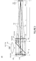
- Fig. 1 shows a side view of a projection display 100 in accordance with an embodiment of the present invention.
- the projection display 100 shown in Fig. 1 comprises a light source 110, a reflective image generator 120, a two-dimensional arrangement 132 of optical projection elements 134 and a beam splitter 140.
- the reflective image generator 120 is configured to represent frames in a two-dimensional distribution 122 of its subareas 124.
- the two-dimensional arrangement 132 of optical projection elements 134 is configured to image an associated subarea 125 of the image generator 120 onto an image plane 150 in each case, so that images of the frames superimpose within the image plane 150 to form an overall picture 160.
- the beam splitter 140 is arranged in an optical path between the reflective image generator 120 and the two-dimensional arrangement 132 of optical projection elements, on the one hand, and in the optical path between the light source 110 and the reflective image generator 120, on the other hand.
- the beam splitter 140 may have a polarizing action
- the reflective image generator 120 may be configured to represent the frames in the form of an influence exerted on the polarization.
- the projection display consists, in particular, of a regular, two-dimensional arrangement of image-generating areas on the reflective image generator 120 configured, for example, as a liquid-crystal image generator 121, a beam splitter 140 configured, for example, as a polarizing beam splitter 142, and the two-dimensional arrangement 132 of optical projection elements 134.
- light of the light source 110 configured as an LED 112, for example, initially passes through condenser optics 115 and is then directed onto the polarizing beam splitter 142. From there, it will finally be reflected, in a polarized state, in the direction of the reflective image generator 120, which is an LCoS (liquid crystal on silicon) image generator, for example.
- LCoS liquid crystal on silicon
- the image generator - which is digital, for example - rotates the polarization direction of the light reflected off it, and thus controls transmission during the second pass through the polarizing beam splitter.
- the fast pixel-by-pixel switching of the voltages, or crystal rotations, enables representing dynamic picture contents.
- the optical projection elements 134 shown in Fig. 1 may be microlenses, for example, configured - in a regular two-dimensional arrangement - as projection objectives which image a subarea 125 of the image generator 120 onto the imaging plane 150 and/or onto a screen in each case. Utilization of such a projection optics arrangement enables drastically reducing the design length of the overall system as compared to conventional single-channel projectors of the same picture size. While a small design length of the inventive projection display or projection system results from focal lengths of the optical projection elements or lenses of a few millimeters, whose focal lengths in turn depend on the dimensions of the beam splitter, multiplication of the object areas or lateral extension ensures a proportional increase in the picture brightness. As compared to miniaturized single-channel projectors, one thus obtains an design length that exceeds the thickness of the beam splitter by only a few millimeters with comparable lateral extension and projection distances.
- the projection picture may arise due to superposition, joining or interleaving the images of single channels of the arrangement.
- the optical projection elements 134 have a decentration 135 with regard to the associated subareas 124.
- the decentration may be considered to be a central contraction or dilation with regard to a central optical axis 101, or to be a lateral offset of the optical projection elements 134 with regard to the associated subareas 124 of the image generator 120.
- the decentration of the optical projection elements with regard to the associated frames onto the image generator is decisive for the projection distance, or projection pitch. On account of a large depth of focus of the partial pictures, it is only to a limited extent that said projection distance depends on the focusing of the individual optical projection elements.
- an offset 135 of the respective image-generating structure and the corresponding optical projection element arises, said offset 135 increasing toward the outside from the central optical axis 101 of the two-dimensional arrangement 132 of optical projection elements 134, or from the array center (grid center).
- the resulting slight tilting of the optical axes 103 of external optical projection elements 134, or projectors, in relation to the central optical axis 101, or the central channel, ensures superposition of individual images within the image plane 150 to form the overall picture 160.
- the image plane may be in infinity or may be located at a finite distance from the optical projection element upstream from the image generator or downstream from the image generator.
- the area upstream from the image generator is defined by the area 102 on the right-hand side of, or in, the optical path downstream from the two-dimensional arrangement 132 of optical projection elements 134
- the area downstream from the image generator is defined by the area 104 on the left-hand side of the left of the image generator 120, or on that side of the image generator 120 that faces away from the beam splitter 140.
- the individual images may superimpose, e.g on a screen, to form the overall picture.
- the projection distance, or projection spacing, L of the array projection display (i.e. the distance L of the image plane 150 from the two-dimensional arrangement 132 of optical projection elements 134 perpendicular to it) results from the focal length of the optical projection element f, the center-to-center distance of the optical projection elements p PL and the center-to-center distance of the pictrures p OBJ .
- the center-to-center distance of the optical projection elements is smaller than that of the image-generating structures, a real picture will result at a defined distance.
- the center-to-center distance p PL of the optical projection elements 134 is smaller than the center-to-center distance p OBJ of the associated subareas 124.
- an overall picture 162 superimposing within the image plane 150 is real.
- Fig. 2 shows a side view of a projection display 200 in accordance with a further embodiment of the present invention.
- the optical projection elements 134 of the projection display 200 have a decentration 137 with regard to the associated subareas 124.
- the center-to-center distance p PL of the optical projection elements 134 is larger than the center-to-center distance p OBJ of the associated subareas 124. Therefore, in Fig. 2 , an overall picture 202 superimposing within the image plane 150 is virtual.
- the pitch of the optical projection elements is selected to be larger than that of the partial pictures, the individual optical projection elements being focused such that virtual partial pictures are formed, whereby a virtual overall picture 202 is obtained which is viewed by the observer or eye 210 in transmitted light, as is shown by way of example in Fig. 2 .
- Fig. 3 shows a side view of a projection display in accordance with a further embodiment of the present invention.
- the projection optics arrangement 130 further has an overall lens 310, which cooperates with the two-dimensional arrangement 132 of optical projection elements 134 and is connected downstream with regard to the two-dimensional arrangement 132 of optical projection elements 134.
- downstream means that the overall lens 310 is arranged, within the optical path, downstream from the two-dimensional arrangement 132 of optical projection elements 134.
- the overall lens 310 is configured, in particular, to refocus the collimated beam 315 from the optical projection elements 134, so that the image plane 150 of an overall picture 302 is located within a focal plane of the overall lens 310.
- Fig. 3 This circumstance is depicted in Fig. 3 such that the image plane 150, where the individual images superimpose to form the overall picture 302, has a distance f L from the overall lens 310.
- the distance d PL of the two-dimensional arrangement 132 of optical projection elements 134 from the reflective image generator 120 may be adjusted, e.g., such that it approximately corresponds to the focal length of the optical projection elements 134.
- the optical projection elements 134 are centered with regard to the associated subareas 124 and have a collimating effect. This means that, in this embodiment, the center-to-center distance p PL of the optical projection elements 134 is equal to the center-to-center distance p OBJ of the associated subareas 124.
- the pitch of the partial pictures corresponds to the pitch of the optical projection elements
- the overall lens 310 is arranged, e.g., in the form of a converging lens 312 within the optical path downstream from the two-dimensional arrangement of optical projection elements, or of the array optics, the overall picture 302 will develop within the focal plane of the lens 310.
- a converging lens a real picture is projected onto a screen, whereas a diverging lens creates a virtual picture similarly to the architecture shown in Fig. 2 .
- a vignetting of projection channels 103 that are remote from the axis said vignetting being smaller, e.g., as compared to the architecture shown in Fig. 1 , and the possibility of adjusting different projection distances by using a variable converging or diverging lens, e.g. in the form of a zoom objective or a fluid lens.
- the downstream overall lens 310 shown in Fig. 3 may thus be configured as optics having variable focal lengths, so that a projection distance is adjustable.
- the projection distance L is essentially defined by the focal length f L of the overall lens 310, apart from a longitudinal extension of the projection optics arrangement 130.
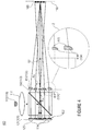
- Fig. 4 shows a side view of an inventive projection display 400.
- the two-dimensional arrangement 132 of optical projection elements 134 is configured as a projection array 410 or as a two-dimensional arrangement, each optical projection element 414 of the projection array 410 comprising a lens vertex 415 decentered toward the aperture of the respective optical projection element.
- the optical projection elements 414, shown in Fig. 4 , of the two-dimensional arrangement 410 essentially correspond to the optical projection elements 134, shown in Figs. 1 to 3 , of the two-dimensional arrangement 132.
- the individual lens vertices 415 of the optical projection elements 414 may be seen more clearly.
- the decentration of the lens vertices 415 may be configured, e.g., such that the optical projection elements 414 of the two-dimensional arrangement 410, put together, achieve a same effect as the projection optics arrangement 130, shown in Fig. 3 , with the downstream overall lens 310.
- Fig. 4 the optical projection elements 414 of the two-dimensional arrangement 410, put together, achieve a same effect as the projection optics arrangement 130, shown in Fig. 3 , with the downstream overall lens 310.
- a center-to-center distance p LS of the lens vertices 415 is smaller than the center-to-center distance p OBJ of the associated subareas 124.
- any lens may cause the frame of the respective subarea 125 to be projected onto the image plane 150. There, the images of the frames will superimpose to form the overall picture 160.
- the optical function of the overall lens such as of a converging lens, may be shifted into the projection, or lens, array.
- an optical component is saved, specifically while maintaining the smaller level of vignetting of channels that are remote from the axis.
- FIG. 5 An inventive projection display 500 having a grid arrangement 510 of light sources is depicted.
- the grid arrangement 510 shown in Fig. 5 essentially corresponds to the light source 110 in Figs. 1 to 4 .
- Fig. 5 shows a condenser optics arrangement 515.
- the condenser optics arrangement 515 of Fig. 5 essentially corresponds to the condenser optics 115 in Figs. 1 to 4 .
- Fig. 5 shows a condenser optics arrangement 515.
- the grid arrangement 510 comprises a plurality of light sources 510-1, 510-2, ..., 510-5, each light source having a condenser optics of the condenser optics arrangement 515 associated with it.
- the grid arrangement 510 of light sources and the condenser optics arrangement 515 may be configured such that light from the individual light sources 510-1, 510-2, ..., 510-5 is directed to associated subareas 124 of the image generator 120, respectively, as is depicted in Fig. 5 by illumination paths 501.
- One advantage of the embodiment shown in Fig. 5 is that, due to the superposition of many frames, as is also the case in the arrangements previously described, usually no particular steps need to be taken in order to homogenize the illumination.
- a further advantage in the use of array light sources, such as collimated LED arrays, is the resulting smaller increase in the size of the lateral extension of the overall arrangement.
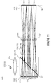
- Fig. 6 shows a side view of an inventive projection display 600 comprising a two-dimension arrangement 610 of field lenses 612.
- the two-dimensional arrangement 610 of field lenses 612 is arranged at least within an optical path between the reflective image generator 120 and the beam splitter 140.
- each field lens 612 in the two-dimensional arrangement 610 is associated with an optical projection element 134 in the two-dimensional arrangement 132 of optical projection elements 134. Due to this utilization of the two-dimensional arrangement 610 of field lenses 612, a Köhler illumination of each optical projection element 134 within the two-dimensional arrangement 132 may be achieved.
- a focal length f FL of the field lenses 612 may be between 1.5 and 2.5 times a focal length f PL of the optical projection elements 134.
- the utilization, shown in Fig. 6 , of the two-dimensional arrangement of field lenses, or of a field lens array, between the beam splitter and the image generator enables the Köhler illumination of the optical projection element, whereby the picture brightness may be increased while simultaneously improving suppression of scattered light.
- the suppression of scattered light may be improved even more in that absorbing diaphragms (not shown in Fig. 6 ) are used within the plane of the field lens array, said diaphragms covering the areas between the lenses.
- absorbing diaphragms not shown in Fig. 6
- utilization of such a diaphragm array between the image generator and the polarizing beam splitter makes sense even without any field lens array for suppressing scattered light.
- illumination may also be effected from several sides by means of corresponding, e.g. collimated, light sources.
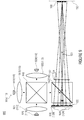
- Fig. 7 shows a side view of an inventive projection display 700 comprising two beam splitters 730, 740 and opposite light sources 710, 720 for two-sided illumination of a reflective image generator.
- the projection display 700 comprises, in particular, first and second light sources 710, 720 and first and second beam splitters 730, 740, which are arranged between the reflective image generator 120 and the two-dimensional arrangement 132 of optical projection elements.
- the first beam splitter 730 is arranged within the optical path between the first light source 710 and a set 750 of subareas of the reflective image generator 120
- the second beam splitter 740 is arranged within the optical path between the second light source 720 and a second set 760 of subareas of the reflective image generator 120.
- a first lateral area 750 of the image generator 120 is illuminated essentially by the first light source 710 and an associated first condenser optics 715
- a second lateral area 760 of the image generator 120 is illuminated essentially by the second light source 720 and an associated second condenser optics 725.
- the first and second light sources 710, 720 and the associated first and second condenser optics 715 and 725 essentially correspond to the light source 110 and to the condenser optics 115, respectively, of the embodiments described above.
- the two-sided illumination shown in Fig. 7 , comprising two light sources 710, 720 and two polarizing beam splitters 730, 740 enables approximate halving of the design length of the projector.
- the optical projection elements may also differ from one another in that they are corrected, in terms of distortion, to a larger extent for the respective color spectrum with which the subarea imaged by the respective optical projection element may be illuminated than for any of the other color spectra of the different color spectra.
- the optical projection elements 134 may be corrected in terms of defocusing and/or astigmatism and/or coma that increases as the distance from the optical axis 101 of the image generator 120 and the projection optics arrangement 130 increases.
- the image generator 120 may be configured such that a size of the subareas 124 continuously changes as the distance from the optical axis 101 of the image generator 120 and the projection optics arrangement 130 increases, so that the frames within the image plane 150 are equally sized.
- an object distance that increases as the distance from the central optical axis 101 or from the central channel increases and, thus, a smaller magnification of external optical projection elements 103 with regard to the central channel in the event of a decentration, as is shown by way of example in Fig. 1 , may be balanced in the projection of the frames onto the image plane 150.
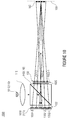
- Fig. 8 shows a side view of an inventive projection display 800 comprising two beam splitters 810, 820 and a half-wave plate 830 that is interposed in the illumination path.
- the projection display 800 of Fig. 8 comprises a second beam splitter 820, in particular, which is arranged within the optical path between the reflective image generator 120 and the two-dimensional arrangement 132 of optical projection elements, on the one hand, and the optical path between the light source 110 and the reflective image generator 120, on the other hand, and a half-wave plate 830 arranged between the first beam splitter 810 and the second beam splitter 820.
- a polarization direction of a polarization component e.g. p
- transmitted through the first beam splitter 810 of light emitted by the light source 110 (polarization components p, s) may be rotated by 90° during passing of the half-wave plate 830.
- the first beam splitter 810 and the second beam splitter 820 are configured to reflect light, which comes from a direction of the light source 110 and has the polarization direction (e.g. s) that is rotated by 90°, in the direction of the image generator 120.
- An exemplary illumination path comprising the respective polarization components is depicted in Fig. 8 by the arrows bearing the designations s, p.
- both polarization components (p, s) of an unpolarized light source such as an LED
- the half-wave plate rotates the polarization component (p) - which is transmitted through the first beam splitter in an unexploited manner - by 90°, so that it will be reflected in the following beam splitter onto the associated half of the image generator with the proper polarization direction (s).
- projection of outer edges of the first 730, 810 and second beam splitters 740, 820 on the reflective image generator 120 may arise such that it does not pass through the subareas 124 of the image generator 120. In this manner, one may avoid that the outer edges have a disturbing effect in the overall picture when they are projected.
- projection of a full-color RGB picture may be realized by an RGB light source 905.
- RGB light source 905 This is possible, e.g., by means of three LEDs 910, 920, 930 comprising associated optical collimation elements 915, 925, 935 and a color combiner 940.
- the RGB light source 905 in the embodiment in Fig. 9 essentially corresponds to the light source 110 of the previous embodiments.
- the RGB light source 905 and the image generator 950 operate in a color-sequentially synchronized manner so as to obtain full-color projection.
- the reflective image generator 950 which essentially corresponds to the image generator 120 of the previous embodiments, may be configured to represent frames 904 from the subareas 124 of the image generator 950 at a sufficiently high frame rate.
- the light source 905 may additionally be configured to sequentially pass through different color components (e.g. red, green, blue) per frame.
- Full-color projection may be realized by means of the color-sequential mode of operation of the image generator 950 and of the individual light sources 910, 920, 930, the picture content of the image generator, which is digital, for example, being identical for all of the projection channels.
- the light source 110, the beam splitter 140, the projection optics arrangement 130, and the reflective image generator 120 may be configured such that reflected light from at least two subareas of the image generator 120 has an identical color spectrum.
- the light source 110 may additionally be arranged such that different subareas of the image generator 120 are illuminated with different color components.
- the first light source 710 may emit light having a first color component, which light is reflected, once it has passed the condenser optics 715, by the first beam splitter 730 onto the first subarea 750 of the image generator 120
- the second light source 720 may emit light having a second color component, which light is reflected, once it has passed the condenser optics 725, by the second beam splitter 740 onto the second subarea 760 of the image generator 120.
- different subareas 750, 760 of the image generator 120 may be illuminated with the first and second color components, which may differ from each other.
- Fig. 10 shows a side view of an inventive projection display 1000 comprising a color filter arrangement 1020 for producing a color mixture within the image plane 150.
- the reflective image generator 1030 which essentially corresponds to the reflective image generator 120 of the previous embodiments, is configured to represent groups 1032-1, 1032-2, 1032-3 of frames, each of which represents a gray-scale value of a color component of a picture content.
- each group 1032-1, 1032-2, 1032-3 of frames may have a respective color filter 1022-1, 1022-2, 1022-3 of the filter arrangement 1020 associated with it.
- the groups 1032-1, 1032-2, 1032-3 of frames may be filtered in accordance with the respective color component so that the overall picture 160 superimposing within the image plane 150 represents a color mixture.
- Fig. 10 represents a different possibility of producing RGB pictures.
- a white light source 1010 By illumination with a white light source 1010 and by inserting RGB color filters 1022-1, 1022-2, 1022-3 into the imaging light path, one primary-color picture is produced, respectively, within a number of projection channels.
- a projection channel corresponds to imaging a subarea of the image generator onto the image plane on the part of an associated optical projection element.
- An RGB projection thus is achieved by associating the corresponding primary-color picture contents with the respective projection channels.
- An advantage of this kind of color generation is the possibility of performing a white balance by means of a number of projection channels for the respective primary color, said number of projection channels being adapted to the spectral characteristic of the light source and the color filters.
- each projecting channel, or a group of optical projection elements may have a separate light source of a primary color assigned to it/them.
- the color mixture is effected during superposition to form the overall picture on the screen or within the virtual picture.
- the light source 110 is configured, e.g., in the form of the light sources 710, 720 so as to illuminate, via the beam splitters 730, 740, the different groups 750, 760 of subareas of the image generator 120 with different color spectra.
- optical projection elements 755, 765 imaging subareas 750, 760 which are illuminated with different color spectra (e.g. red, blue) by the light sources 710, 720, differ from each other.
- the image generator 120 may also be configured such that a size of subareas 750 that may be illuminated with a first one of the different color spectra (e.g. red), differs from a size of subareas 760 that may be illuminated with a second color spectrum (e.g. blue) differing from the first one. In this manner, sizes of the frames within the image plane may be matched to one another.
- a size of subareas 750 that may be illuminated with a first one of the different color spectra e.g. red
- a second color spectrum e.g. blue
- the representation of the color may also be realized-apart from the above-mentioned direct colored illumination of the subareas - by the color filter arrangement shown by way of example in Fig. 10 , so that different groups of subareas contribute with different color spectra to the overall picture.
- a same focal length may be selected for all of the optical projection elements within the two-dimensional arrangement of optical projection elements for all of the different color channels, i.e. for optical channel associated different color spectra, so that an identical magnification results for all of the different color channels.
- different geometric distances of the optical projection elements from the reflective image generator are set, different optical path lengths that are due to a dispersion of the beam splitter (e.g. of the first or second beam splitters 730, 740) may be balanced out for the different color channels.
- the optical projection elements may be undesirable to arrange the optical projection elements within the two-dimensional arrangement of optical projection elements at different design heights. Therefore, it may be advantageous to keep the optical projection elements at an identical geometric distance from the reflective image generator.
- the different optical path lengths that are due to the dispersion of the beam splitter may be balanced out by selecting different focal lengths of the optical projection elements in accordance with the different optical path lengths for the different color channels.
- the different focal lengths result in that different magnifications will result, within the image plane, for the different color channels.
- the respective magnification, or the respective imaging scale may be readjusted by different sizes of the subareas associated with the different color channels by using a software (i.e. in a computer-controlled manner).
- the beam splitter may not be configured to be cube-shaped, but as platelets, so that a difference between the different optical path lengths that are due to a relatively small dispersion is negligible.
- a correction of the longitudinal color defects of the image may thus be anticipated by adapting the focal lengths of the optical projection elements of the primary-color arrays in a color-group-wise manner.
- correction of the transverse color defect of the imaging may be anticipated by adapting the partial picture sizes of the primary-color partial pictures in a color-group-wise manner.
- a further advantage of the present invention thus is the possibility to correct abberations in the form of channel-by-channel correction of chromatic aberrations, such as the longitudinal color defects, of the optical projection elements. If there are different imaging scales for the primary colors, correction of the resulting transverse color defect in the overall picture by means of different picture sizes of the primary-color partial pictures, is also possible, for example.
- correction of the distortion may be anticipated by a pre-distortion of the partial pictures.
- defocusing of projection channels that are remote from the axis may be performed, additionally, by means of a focal length of the optical projection elements that is adapted in a channel-wise manner.
- an inventive projection display may also be characterized in that the different imaging scales of central channels, or channels that are remote from the axis - said different imaging scales resulting from an adaptation of the focal length - are corrected by a size that is changed channel by channel, and by a pre-distortion of partial pictures that are remote from the axis.
- astigmatism and coma may be corrected with different sagittal and tangential focal lengths of optical projection elements that are remote from the axis, said focal lengths being adapted in a channel-wise manner.
- channel-by-channel correction of monochromatic abberations such as the influence of the image field curvature for relatively large object distances of projection channels that are remote from the axis, or the distortion, along with pre-distortions - which are dependent on the distance of the optical projection element from the axis - of the partial pictures enables simple solutions for improving the picture quality.
- the correction of monochromatic abberations generally requires the respective optical projection element to be adapted in dependence on the position of the respective projection channel in relation to the array center.
- lens arrays having focal lengths that continuously vary across the array, for elliptic microlenses also separated into sagittal and meridional focal lengths are suited for correcting astigmatism and coma.
- a further possibility of producing color pictures is to use an array light source, as is shown, e.g., in Fig. 5 in the form of the light source 510 comprising the corresponding condenser optics arrangement 515, for example comprising LEDs of different luminous colors.
- Unambiguous association of the individual light sources with groups of partial pictures and optical projection elements is then advantageously achieved by using a field lens array, as is shown in Fig. 6 by way of example. Omission of color filters here enables higher system transmission than in the suggested solution described above.
- the reflective image generator 120 and the projection optics arrangement 130 may be configured such that identical frames from different subareas are superimposed in a pixel-accurate manner.
- the image generator 120 may be configured to display different frames. Said frames being imaged by the associated optical projection elements results in the overall picture, or projection picture.
- Fig. 11 shows an inventive projection display 1100, wherein images of frames superimpose within an image plane 150 to form an overall picture 1130 having a higher resolution, or a higher number of pixels represented.
- the reflective image generator 1110 and the projection optics arrangement 1120 may be configured such that the images of the frames within the image plane 150 superimpose one another with a mutual subpixel offset.
- the optical projection elements 1122 in the two-dimensional arrangement 1120 have a decentration, depicted in Fig. 11 by way of example, with regard to the associated subareas 124. As is shown in Fig. 11 by way of example, this results in an overall picture 1130 superimposing within the image plane 150 and having a higher resolution, or higher pixel number represented, than the frames.
- the overall picture 1130 is composed of three projected partial pictures 1132-1, 1132-2, 1132-3, said partial pictures being joined together and imaged via two projection channels 1101, respectively.
- Fig. 12 shows a schematic representation for illustrating an inventive superposition 1200 of pixels for form an overall picture 19.
- the realization shown in Fig. 12 is advantageous in particular for image generators having low pixel fill factors.
- a pixel 16a, 16b, 16c or 16d of the image generator is generally composed of an inactive surface area 17a, 17b, 17c or 17d and an active area 18a, 18b, 18c or 18d.
- pixel 16a be white
- 16b be light gray
- pixel 16c be dark gray
- pixel 16d be black.
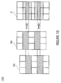
- Fig. 13 shows a schematic representation for illustrating an inventive superposition 1300 of binary black and white partial pictures to form an overall picture 21. If the image generator has a high fill factor, the superposition with a subpixel offset in the overall picture 21 results in a combination of an increased number of gray-scale values and an increase in the number of pixels that may be represented. In Fig. 13 , this circumstance is represented using the example of a banded structure.
- the purely binary black and white partial pictures 20a, 20b superimpose each other to form an overall picture 21 having an increased number of gray scales and an increased number of pixels that may be represented.
- Fig. 14 shows a schematic representation for illustrating a further inventive superposition 1400 of binary black and white partial pictures to form an overall picture 23.
- Fig. 14 depicts purely binary black and white partial pictures 22a, 22b, whose superposition to form the overall picture 23 already provides three gray scales.
- a further increase in the different binary pictures further increases the number of gray scales that may be represented.
- This approach to increasing the number of gray scales may also be used for non-purely binary pictures, but generally for partial pictures having few gray scales. Combining said approach with the above-described procedure of representing full-color pictures correspondingly enables an increase in the depth of color.
- the inventive projection display may thus be configured to receive a picture to be projected that has a first gray/color scale resolution, the reflective image generator 120 being configured to represent the frames (i.e. the binary black and white partial pictures 20a, 20b; 22a, 22b) with a second gray/color scale resolution smaller than the first gray/color scale resolution.
- the projection display may be configured to control the subareas - in dependence on a gray/color scale value of the projected image - at a picture point, or pixel, of the image to be projected, such that in the overall picture 21; 23, the frames will add up, at a location corresponding to the picture point, to yield a gray/color scale corresponding to the gray/color scale value.
- Fig. 15 shows a top view of an inventive reflective image generator 1500 having two different modes for different magnifications and/or different projection distances of an image.
- the reflective image generator 1500 which essentially corresponds to the image generator 120 of the previous embodiments, comprises different modes for adjusting the distribution of subareas, so that from a first mode (continuous line) to a second mode (dashed line) of the image generator 1500, an extent of a decentration 1510 between the optical projection elements 1520 and the associated subareas 1530-1 in the first mode and/or 1530-2 in the second mode changes so as to achieve different magnifications and/or different projection distances in the first mode and in the second mode of the image generator 1500.
- Fig. 15 shows a top view of an inventive reflective image generator 1500 having two different modes for different magnifications and/or different projection distances of an image.
- the decentration 1510 is exemplarily depicted by vectors.
- the vectors correspond to the lateral offset, or to the central shifts, in the decentration between the subareas 1530-1, 1530-2 in the first and second modes, respectively, and the optical projection elements 1520.
- the decentration 1510 is adjusted, for example, such that in the first mode, the optical projection elements 1520 are centered in relation to the subareas 1530-1, whereas in the second mode, the optical projection elements 1520 are centrally contracted in relation to the subareas 1530-2 with regard to the central optical axis 101.
- the decentration 1510 may also be adjusted such that in the second mode, the optical projection elements 1520 have a central dilation with regard to the central optical axis 101 in relation to the subareas 1530-2.
- a predefined projection distance may be adjusted in a variable manner by electronically adjusting the centration.
- the image generator 1500 may also have a multitude of such modes which enable purely electronic focusing of the representation within a large range of projection distances.
- the first mode and the second mode of the image generator 1500 may also be adjusted in dependence on a projection distance measured.
- the projection distance may thus be effectively readjusted electronically.
- the projection distance may be measured using a proximity sensor for measuring the distance from the screen, which enables automatic focusing of the projector.
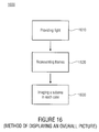
- Fig. 16 shows a flowchart of a method 1600 for displaying an overall picture in accordance with embodiments of the present invention.
- the method 1600 comprises the following steps, for example. Initially, light is provided using a light source (step 1610). Subsequently, frames are represented in a two-dimensional distribution of subareas using a reflective image generator (step 1620).
- a subarea of the image generator is imaged onto an image plane, respectively, by a projection optics arrangement having a two-dimensional arrangement of optical projection elements, the subarea being associated with the optical projection elements in each case, so that images of the frames superimpose within the image plane to form an overall picture, a beam splitter being arranged within an optical path between the reflective image generator and the two-dimensional arrangement of optical projection elements, on the one hand, and the optical path between the light source and the reflective image generator, on the other hand (step 1630).
- Embodiments of the present invention thus provide a projection display consisting of at least one light source, at least one reflective, digital image generator, for example on a liquid-crystal basis (LCoS), at least one, e.g. polarizing, beam splitter, and a regular arrangement of optical projection channels, for example in the form of one- or multi-layer optical elements.
- the individual projectors superimpose one another or compose their projection pictures to form a real picture on the screen, or to form a virtual picture in transmission.
- An advantage of the present invention is that a technically complex correction of the imaging errors, in particular complex achromatization of the optical projection element, is not required.
- an inventive image generator has a high pixel error tolerance, which may result in lower manufacturing cost of image generators.
- the present invention is also advantageous in that no mechanically moved lenses are required for fine-focusing with changing projection distances.
- embodiments of the present invention provide an optical concept for realizing very flat and, at the same time, very bright projection systems, for example on the basis of a reflective liquid-crystal image generator.
- a reflective liquid-crystal image generator such as LCoS, D-ILA (digital direct drive image light amplifier) or SXRD (silicon X-tal reflective display)
- the present arrangement overcomes direct dependence on system design length and transmissible luminous flux by using an optical multi-channel approach.
- Feasible applications are in the fields of personal communication and consumer electronics as well as data visualization for home and for mobile use.
- a further field of application is in the automobiles and aircraft, in the form of a head-up display for projecting representation of color state information, navigation, environment information as driver assistance systems and/or for entertaining passengers.
- Also feasible are applications in measurement and medical technology as well as in display applications in industrial and manufacturing plants.
Landscapes
- Physics & Mathematics (AREA)
- General Physics & Mathematics (AREA)
- Engineering & Computer Science (AREA)
- Multimedia (AREA)
- Signal Processing (AREA)
- Optics & Photonics (AREA)
- Projection Apparatus (AREA)
- Liquid Crystal (AREA)
- Optical Elements Other Than Lenses (AREA)
- Liquid Crystal Display Device Control (AREA)
- Control Of Indicators Other Than Cathode Ray Tubes (AREA)
Claims (29)
- Projektionsdisplay (100) mit
einer Lichtquelle (110),
einem reflektiven Bildgeber (120), der ausgebildet ist, um in einer zweidimensionalen Verteilung (122) von Teilbereichen (124) des reflektiven Bildgebers Teilbilder darzustellen, wobei jedes Teilbild eine Mehrzahl von Pixeln aufweist,
einer Projektionsoptikanordnung (130) mit einer zweidimensionalen Anordnung (132) von Projektionsoptiken (134), die jeweils konfiguriert sind, um einen zugeordneten Teilbereich (125) des Bildgebers (120) auf eine Bildebene (150) zu projizieren, so dass sich Abbildungen der Teilbilder in der Bildebene (150) überlagern, um ein Gesamtbild (160) zu bilden, und
einem Strahlteiler (140), der in einem Strahlengang zwischen dem reflektiven Bildgeber (120) und der zweidimensionalen Anordnung (132) von Projektionsoptiken (134) einerseits und im Strahlengang zwischen der Lichtquelle (110) und der zweidimensionalen Verteilung von Teilbereichen andererseits angeordnet ist, so dass Licht der Lichtquelle durch den Strahlteiler auf die zweidimensionale Verteilung von Teilbereichen gelangt, und die Projektion der zweidimensionalen Verteilung von Teilbereichen durch den Strahlteiler führt. - Das Projektionsdisplay nach Anspruch 1, bei dem der Strahlteiler (142) polarisierend wirkt und der reflektive Bildgeber (121) ausgebildet ist, die Teilbilder in Form einer Polarisationsbeeinflussung darzustellen.
- Das Projektionsdisplay nach Anspruch 1 oder 2, bei dem die Projektionsoptiken (134) eine Dezentrierung (135) bezüglich der zugeordneten Teilbereiche (124) aufweisen, bei der ein Mittenabstand (pPL) der Projektionsoptiken (134) kleiner als ein Mittenabstand (pOBJ) der zugeordneten Teilbereiche (124) ist, so dass das sich in der Bildebene (150) überlagernde Gesamtbild (162) reell ist.
- Das Projektionssystem nach Anspruch 1 oder 2, bei dem die Projektionsoptiken (134) eine Dezentrierung (137) bezüglich der zugeordneten Teilbereiche (124) aufweisen, bei der der Mittenabstand (pPL) der Projektionsoptiken (134) größer oder gleich dem Mittenabstand (pOBJ) der zugeordneten Teilbereiche (124) ist, so dass das sich in der Bildebene (150) überlagernde Gesamtbild (202) virtuell ist.
- Das Projektionsdisplay nach einem der Ansprüche 1, 2 und 4, wobei die Projektionsoptiken (134) bezüglich der zugeordneten Teilbereiche (124) zentriert sind und kollimierend wirken.
- Das Projektionsdisplay nach Anspruch 1 oder 2, bei dem die Projektionsoptikanordnung (130) ferner eine Gesamtlinse aufweist, die bezüglich der zweidimensionalen Anordnung von Projektionsoptiken nachgeschaltet ist und mit der zweidimensionalen Anordnung von Projektionsoptiken zusammenwirkt, wobei die Gesamtlinse ausgebildet ist, um kollimierte Strahlenbündel von den Projektionsoptiken zu refokussieren, so dass die Bildebene des Gesamtbilds in einer Brennebene der Gesamtlinse liegt, wobei die Projektionsoptiken (134) bezüglich der zugeordneten Teilbereiche (124) zentriert sind und kollimierend wirken.
- Das Projektionsdisplay nach Anspruch 6, bei dem die Gesamtlinse (310, 312) als Optik mit variabler Brennweite ausgebildet ist, so dass eine Projektionsdistanz einstellbar ist.
- Das Projektionsdisplay nach Anspruch 7, bei dem die Optik mit variabler Brennweite ein Zoomobjektiv oder eine Flüssigkeitslinse ist.
- Das Projektionsdisplay nach Anspruch 1 oder 2, bei dem jede Projektionsoptik (414) einen zur Apertur der jeweiligen Projektionsoptik dezentrierten Linsenscheitel (415) aufweist, wobei ein Mittenabstand der Linsenscheitel (415) größer oder kleiner als der Mittenabstand der zugeordneten Teilbereiche (124) ist, so dass die Linsen eine Projektion des Teilbilds des jeweiligen Teilbereichs auf die Bildebene (150) bewirken, wo sich die Abbildungen der Teilbilder zum Gesamtbild (160) überlagern.
- Das Projektionsdisplay nach einem der Ansprüche 1 bis 9, bei dem zumindest in einem Strahlengang zwischen dem reflektiven Bildgeber (120) und dem Strahlteiler (140) eine zweidimensionale Anordnung (610) von Feldlinsen (612), die den Projektionsoptiken (134) zugeordnet sind, angeordnet ist, so dass eine Köhlersche Beleuchtung jeder Projektionsoptik (134) der zweidimensionalen Anordnung (132) von Projektionsoptiken erzielt wird.
- Das Projektionsdisplay nach Anspruch 10, bei dem eine Brennweite (fFL) der Feldlinsen (612) zwischen dem 1,5-fachen und dem 2,5-fachen einer Brennweite (fPL) der Projektionsoptiken (134) liegt.
- Das Projektionsdisplay nach einem der Ansprüche 1 bis 11, das einen ersten (810) und einen zweiten Strahlteiler (820), die zwischen dem reflektiven Bildgeber (120) und der mindestens einen zweidimensionalen Anordnung (132) von Projektionsoptiken einerseits und im Strahlengang zwischen der Lichtquelle (110) und dem reflektiven Bildgeber (120) andererseits angeordnet sind, und eine Halbwellenlängeplatte (830), die zwischen dem ersten Strahlteiler (810) und dem zweiten Strahlteiler (820) angeordnet ist, aufweist, so dass eine Polarisationsrichtung einer durch den ersten Strahlteiler (810) transmittierten Polarisationskomponente eines von der Lichtquelle (110) emittierten Lichts beim Passieren der Halbwellenlängenplatte (830) um 90° gedreht wird, wobei der erste Strahlteiler (810) und der zweite Strahlteiler (820) ausgebildet sind, Licht aus einer Richtung der Lichtquelle (110) mit der um 90° gedrehten Polarisationsrichtung in Richtung des Bildgebers (120) zu reflektieren.
- Das Projektionsdisplay nach einem der Ansprüche 1 bis 12, das eine erste (710) und eine zweite Lichtquelle (720) und einen ersten (730) und einen zweiten Strahlteiler (740), die zwischen dem reflektiven Bildgeber (120) und der mindestens einen zweidimensionalen Anordnung (132) von Projektionsoptiken angeordnet sind, aufweist, wobei der erste Strahlteiler (730) im Strahlengang zwischen der ersten Lichtquelle (710) und einem ersten Satz (750) von Teilbereichen des reflektiven Bildgebers (120) und der zweite Strahlteiler (740) im Strahlengang zwischen der zweiten Lichtquelle (720) und einem zweiten Satz (760) von Teilbereichen des Bildgebers (120) angeordnet sind.
- Das Projektionsdisplay nach Anspruch 13 oder 14, bei dem eine Projektion von Außenkanten des ersten (730, 810) und zweiten Strahlteilers (740, 820) auf dem reflektiven Bildgeber (120) so entsteht, dass sie nicht durch die Teilbereiche (124) des Bildgebers (120) verläuft.
- Das Projektionsdisplay nach einem der Ansprüche 1 bis 14, wobei der reflektive Bildgeber (950) ausgebildet ist, um die Teilbilder mit einer hinreichend hohen Frame-Rate darzustellen, und wobei die Lichtquelle (905) ausgebildet ist, um pro Frame sequenziell unterschiedliche Farbkomponenten zu durchlaufen.
- Das Projektionsdisplay nach einem der vorhergehenden Ansprüche, bei dem die Lichtquelle (110), der Strahlteiler (140), die Projektionsoptikanordnung (130) und der reflektive Bildgeber (120) so ausgebildet sind, dass reflektiertes Licht von zumindest zwei Teilbereichen des Bildgebers (120) ein gleiches Farbspektrum aufweist.
- Das Projektionsdisplay nach einem der vorhergehenden Ansprüche, bei dem die Lichtquelle (710, 720) so angeordnet ist, dass unterschiedliche Teilbereiche (750, 760) des Bildgebers (120) mit unterschiedlichen Farbkomponenten angestrahlt werden.
- Das Projektionsdisplay nach einem der vorhergehenden Ansprüche, bei dem der reflektive Bildgeber (120) ausgebildet ist, um Gruppen von Teilbildern (1032-1, 1032-2, 1032-3), die jeweils einen Grauwert einer Farbkomponente eines Bildinhalts repräsentieren, darzustellen, wobei jeder Gruppe von Teilbildern (1032-1, 1032-2, 1032-3) Farbfilter (1022-1, 1022-2, 1022-3) zugeordnet sind, so dass die Gruppen von Teilbildern (1032-1, 1032-2, 1032-3) entsprechend der jeweiligen Farbkomponente gefiltert werden, so dass das sich in der Bildebene (150) überlagernde Gesamtbild (160) eine Farbmischung darstellt.
- Das Projektionsdisplay nach einem der vorhergehenden Ansprüche, bei dem der reflektive Bildgeber (120) und die Projektionsoptikanordnung (130) derart ausgebildet sind, dass identische Teilbilder aus unterschiedlichen Teilbereichen pixelgenau überlagert werden.
- Das Projektionsdisplay nach einem der vorhergehenden Ansprüche, das ausgebildet ist, ein zu projizierendes Bild mit einer ersten Grau/Farbstufenauflösung zu empfangen, wobei der reflektive Bildgeber (120) ausgebildet ist, die Teilbilder (20a, 20b; 22a, 22b) mit einer zweiten Grau/Farbstufenauflösung darzustellen, die kleiner ist als die erste Grau/Farbstufenauflösung, wobei das Projektionsdisplay ausgebildet ist, um abhängig von einem Grau/Farbstufenwert des zu projizierendes Bild an einem Bildpunkt des zu projizierenden Bilds die Teilbereiche so anzusteuern, das sich im Gesamtbild (21, 23) die Teilbilder an einer dem Bildpunkt entsprechenden Stelle zu einer dem Grau/Farbstufenwert entsprechenden Grau/Farbstufe aufsummieren.
- Das Projektionsdisplay nach einem der Ansprüche 1 bis 18, bei dem der reflektive Bildgeber (120) und die Projektionsoptikanordnung (130) derart ausgebildet sind, dass sich die Abbildungen der Teilbilder in der Bildebene (150) mit einem Subpixelversatz zueinander überlagern, wobei die Projektionsoptiken (134) eine Dezentrierung bezüglich der zugeordneten Teilbereiche (124) aufweisen, so dass das sich in der Bildebene (150) überlagernde Gesamtbild (19) eine höhere Auflösung als die Teilbilder hat.
- Das Projektionsdisplay nach einem der Ansprüche 1 bis 21, bei dem der reflektive Bildgeber (1500) unterschiedliche Modi hat, um die Verteilung von Teilbereichen (1530-1, 1530-2) einzustellen, so dass sich von einem ersten Modus zu einem zweiten Modus des Bildgebers ein Ausmaß einer Dezentrierung zwischen den Projektionsoptiken (1520) und den zugeordneten Teilbereichen verändert, um in dem ersten Modus und in dem zweiten Modus des Bildgebers (1500) unterschiedliche Projektionsdistanzen und/oder unterschiedliche Vergrößerungen zu erzielen.
- Das Projektionsdisplay nach Anspruch 22, bei dem der erste Modus und der zweite Modus des Bildgebers (1500) abhängig von einer gemessenen Projektionsdistanz einstellbar sind.
- Das Projektionsdisplay nach einem der vorhergehenden Ansprüche, bei dem der Strahlteiler aus dispersivem Material ist und unterschiedliche Gruppen (750, 760) von Teilbereichen zum Gesamtbild mit unterschiedlichem Farbspektrum beitragen, wobei innerhalb der zweidimensionalen Anordnung (132) von Projektionsoptiken (755, 765) Projektionsoptiken, die Teilbereiche (750, 760) abbilden, die mit zueinander unterschiedlichen Farbspektren zum Gesamtbild beitragen, in einem gleichen geometrischen Abstand zu dem Bildgeber angeordnet sind, aber sich zum Ausgleich unterschiedlicher optischer Weglängen zwischen dem Bildgeber und den Projektionsoptiken für das jeweilige Farbspektrum voneinander in ihren Brennweiten unterscheiden.
- Das Projektionsdisplay nach einem der vorhergehenden Ansprüche, bei dem der Strahlteiler aus dispersivem Material ist und unterschiedliche Gruppen (750, 760) von Teilbereichen zum Gesamtbild mit unterschiedlichem Farbspektrum beitragen, wobei innerhalb der zweidimensionalen Anordnung (132) von Projektionsoptiken (755, 765) Projektionsoptiken, die Teilbereiche (750, 760) abbilden, die mit zueinander unterschiedlichen Farbspektren zum Gesamtbild beitragen, eine gleiche Brennweite haben, aber zur Anpassung optischer Weglängen zwischen dem Bildgeber und den Projektionsoptiken für das jeweilige Farbspektrum in zueinander unterschiedlichen geometrischen Abständen zu dem reflektiven Bildgeber angeordnet sind.
- Das Projektionsdisplay nach einem der Ansprüche 1 bis 25, bei dem unterschiedliche Gruppen (750, 760) von Teilbereichen zum Gesamtbild mit unterschiedlichem Farbspektrum beitragen, wobei der Bildgeber (120) so ausgebildet ist, dass sich eine Größe von Teilbereichen (750), die mit einem ersten der unterschiedlichen Farbspektren zum Gesamtbild beitragen, von einer Größe von Teilbereichen (760), die mit einem zweiten, zu dem ersten unterschiedlichen der unterschiedlichen Farbspektren zum Gesamtbild beitragen, unterscheidet, so dass eine Größe der Teilbilder in der Bildebene (150) aufeinander abgestimmt ist.
- Das Projektionsdisplay nach einem der vorhergehenden Ansprüche, bei dem in der zweidimensionalen Anordnung (132) von Projektionsoptiken die Projektionsoptiken (134) gegen eine mit anwachsender Entfernung von einer optischen Achse (101) des Bildgebers (120) und der Projektionsoptikanordnung (130) wachsende Defokussierung und/oder Astigmatismus und/oder Koma korrigiert sind.
- Das Projektionsdisplay nach Anspruch 27, bei dem der Bildgeber (120) so ausgebildet ist, dass sich eine Größe der Teilbereiche (124) mit anwachsender Entfernung von der optischen Achse (101) des Bildgebers (120) und der Projektionsoptikanordnung (130) kontinuierlich verändert, so dass die Teilbilder in der Bildebene (150) gleich groß sind.
- Verfahren (1600) zum Anzeigen eines Gesamtbilds (160), mit:Bereitstellen (1610) von Licht mit einer Lichtquelle (110);Darstellen (1620) von Teilbildern in einer zweidimensionalen Verteilung (122) von Teilbereichen (124) eines reflektiven Bildgebers, wobei jedes Einzelbild eine Mehrzahl von Pixeln aufweist, unter Verwendung des reflektiven Bildgebers (120);Projizieren (1630) eines Teilbereichs des Bildgebers (120) auf eine Bildebene (150) durch eine Projektionsoptikanordnung (130) mit einer zweidimensionalen Anordnung (132) von Projektionsoptiken, wobei jeder Teilbereich einer der Projektionsoptiken zugeordnet ist, so dass sich Abbildungen der Teilbilder in der Bildebene (150) überlagern, um ein Gesamtbild (160) zu bilden, wobei ein Strahlteiler (140) in einem Strahlengang zwischen dem reflektiven Bildgeber (120) und der zweidimensionalen Anordnung (132) von Projektionsoptiken einerseits und dem Strahlengang zwischen der Lichtquelle (110) und der zweidimensionalen Verteilung von Teilbereichen andererseits angeordnet ist, so dass Licht der Lichtquelle durch den Strahlteiler auf die zweidimensionale Verteilung von Teilbereichen fällt, und die Projektion der zweidimensionalen Verteilung von Teilbereichen durch den Strahlteiler führt.
Applications Claiming Priority (2)
| Application Number | Priority Date | Filing Date | Title |
|---|---|---|---|
| DE102010030138A DE102010030138A1 (de) | 2010-06-15 | 2010-06-15 | Projektionsdisplay und Verfahren zum Anzeigen eines Gesamtbilds |
| PCT/EP2011/059618 WO2011157632A1 (en) | 2010-06-15 | 2011-06-09 | Projection display and method of displaying an overall picture |
Publications (2)
| Publication Number | Publication Date |
|---|---|
| EP2583465A1 EP2583465A1 (de) | 2013-04-24 |
| EP2583465B1 true EP2583465B1 (de) | 2016-10-05 |
Family
ID=44317914
Family Applications (1)
| Application Number | Title | Priority Date | Filing Date |
|---|---|---|---|
| EP11724230.5A Active EP2583465B1 (de) | 2010-06-15 | 2011-06-09 | Projektionsanzeige und verfahren zur anzeige eines gesamtbildes |
Country Status (8)
| Country | Link |
|---|---|
| US (1) | US8794770B2 (de) |
| EP (1) | EP2583465B1 (de) |
| JP (1) | JP5719650B2 (de) |
| KR (1) | KR101325174B1 (de) |
| DE (1) | DE102010030138A1 (de) |
| DK (1) | DK2583465T3 (de) |
| TW (1) | TWI454826B (de) |
| WO (1) | WO2011157632A1 (de) |
Families Citing this family (36)
| Publication number | Priority date | Publication date | Assignee | Title |
|---|---|---|---|---|
| US8976080B2 (en) | 2005-12-06 | 2015-03-10 | Dolby Laboratories Licensing Corporation | Multi-segment imager |
| DE102009024894A1 (de) * | 2009-06-15 | 2010-12-16 | Fraunhofer-Gesellschaft zur Förderung der angewandten Forschung e.V. | Projektionsdisplay und dessen Verwendung |
| JP5674032B2 (ja) * | 2011-03-25 | 2015-02-18 | 日本精機株式会社 | ヘッドアップディスプレイ装置 |
| CN102540671A (zh) * | 2012-02-15 | 2012-07-04 | 凝辉(天津)科技有限责任公司 | 光驱动分离式微型激光投影装置 |
| WO2013130037A1 (en) * | 2012-02-27 | 2013-09-06 | Dolby Laboratories Licensing Corporation | Multi-segment imager |
| DE102012205164B4 (de) * | 2012-03-29 | 2021-09-09 | Fraunhofer-Gesellschaft zur Förderung der angewandten Forschung e.V. | Projektionsdisplay und Verfahren zur Projektion virtueller Bilder |
| DE102012207621A1 (de) * | 2012-05-08 | 2013-11-14 | Fraunhofer-Gesellschaft zur Förderung der angewandten Forschung e.V. | Projektionsdisplay mit mehrkanaloptik mit nicht kreisförmiger gesamtapertur |
| DE102012221310B4 (de) * | 2012-11-22 | 2019-09-19 | Sypro Optics Gmbh | Anzeigeanordnung für ein Kraftfahrzeug, mit einem Bildgeber und einem Bildtrenner |
| DE102013207257B4 (de) * | 2013-04-22 | 2021-03-04 | Carl Zeiss Jena Gmbh | Anzeigevorrichtung |
| DE102013207243B4 (de) * | 2013-04-22 | 2019-10-02 | Fraunhofer-Gesellschaft zur Förderung der angewandten Forschung e.V. | Vorrichtung und verfahren zur herstellung einer struktur aus aushärtbarem material durch abformung |
| DE102013208625A1 (de) * | 2013-05-10 | 2014-11-13 | Fraunhofer-Gesellschaft zur Förderung der angewandten Forschung e.V. | Multiapertur-projektionsdisplay und einzelbilderzeuger für ein solches |
| JP6277816B2 (ja) * | 2014-03-26 | 2018-02-14 | セイコーエプソン株式会社 | プロジェクター |
| JP6287605B2 (ja) * | 2014-06-09 | 2018-03-07 | 株式会社デンソー | ヘッドアップディスプレイ装置及びその照明ユニット |
| EP3021072B1 (de) | 2014-11-14 | 2016-09-28 | Sick Ag | Beleuchtungsvorrichtung und Verfahren zur Projektion eines Beleuchtungsmusters |
| DE102015115240A1 (de) | 2015-09-10 | 2017-03-16 | Hella Kgaa Hueck & Co. | Fahrzeug mit Lichtprojektionssystem und Verfahren zur Erzeugung einer Sicherheitsmarkierung auf einer Bodenoberfläche |
| DE102015115242A1 (de) | 2015-09-10 | 2017-03-16 | Hella Kgaa Hueck & Co. | Fahrzeug mit Lichtprojektionssystem und Verfahren zur Erzeugung eines Sicherheitsbereichs auf einer Bodenoberfläche |
| DE102015115239A1 (de) | 2015-09-10 | 2017-03-16 | Hella Kgaa Hueck & Co. | Fahrzeug mit Lichtprojektionssystem und Verfahren zur Beurteilung der Topographie einer Bodenoberfläche |
| DE102015218829B4 (de) | 2015-09-30 | 2018-08-16 | Bayerische Motoren Werke Aktiengesellschaft | Bilderzeugungsvorrichtung und Verfahren zur Herstellung eines Arrays bildgebender Elemente |
| DE102015121691A1 (de) | 2015-12-14 | 2017-06-14 | Hella Kgaa Hueck & Co. | Verfahren zur Herstellung eines Mikrolinsenarrays |
| CN105842905B (zh) * | 2016-05-25 | 2018-08-03 | 京东方科技集团股份有限公司 | 一种虚拟曲面显示面板及显示装置 |
| CN106094405B (zh) | 2016-06-03 | 2017-11-21 | 海信集团有限公司 | 投影图像校正方法、装置和投影机 |
| DE102016115938A1 (de) * | 2016-08-26 | 2018-03-01 | Carl Zeiss Jena Gmbh | Wellenleiter sowie Vorrichtungen zur Dateneinspiegelung |
| TWM546331U (zh) * | 2016-12-16 | 2017-08-01 | 揚明光學股份有限公司 | 用以迎賓燈之燈具 |
| FI129873B (en) * | 2017-05-08 | 2022-10-14 | Dispelix Oy | Diffractive display, light guide element and projector, and method of displaying image |
| DE102017111607B4 (de) | 2017-05-29 | 2020-09-24 | tooz technologies GmbH | Abbildungsvorrichtung, Datenbrille und Verfahren zum Generieren eines Bildes aus einem Ausgangsbild in einer Datenbrille |
| WO2020061714A1 (en) * | 2018-09-28 | 2020-04-02 | Peckham Jordan | Direct projection light field display |
| CN110191328A (zh) * | 2019-06-19 | 2019-08-30 | 广景视睿科技(深圳)有限公司 | 一种动向投影装置、方法及投影仪 |
| CN112815272B (zh) * | 2019-11-18 | 2023-10-10 | 深圳市绎立锐光科技开发有限公司 | 光源系统和发光设备 |
| KR102926516B1 (ko) * | 2020-09-16 | 2026-02-10 | 삼성전자주식회사 | 다중 영상 디스플레이 장치 |
| CN215895101U (zh) * | 2021-06-10 | 2022-02-22 | 浙江棱镜全息科技有限公司 | 基于图像拼接的空中成像装置 |
| DE102022103302A1 (de) | 2022-02-11 | 2023-08-17 | Marcel Sieler | Projektionsdisplay |
| EP4476586A1 (de) | 2022-02-11 | 2024-12-18 | Marcel Sieler | Projektionsdisplay |
| JP2024179345A (ja) * | 2023-06-14 | 2024-12-26 | マクセル株式会社 | ヘッドアップディスプレイ及び乗り物 |
| DE102023121900A1 (de) | 2023-08-16 | 2025-02-20 | Carl Zeiss Jena Gmbh | Zeitmultiplexen zur korrektur von farb-aberrationen in einer transparenten bildschirmeinheit |
| FR3157519A1 (fr) * | 2023-12-22 | 2025-06-27 | Valeo Vision | Module lumineux pour véhicule automobile |
| DE102024112487A1 (de) * | 2024-05-03 | 2025-11-06 | Marelli Germany Gmbh | Mikrolinsen-Projektionsmodul |
Citations (2)
| Publication number | Priority date | Publication date | Assignee | Title |
|---|---|---|---|---|
| US4969734A (en) * | 1986-05-09 | 1990-11-13 | Greyhawk Systems, Inc. | Apparatus and method of forming and projecting high precision optical images |
| JP2008122641A (ja) * | 2006-11-13 | 2008-05-29 | Victor Co Of Japan Ltd | 投射型表示装置 |
Family Cites Families (27)
| Publication number | Priority date | Publication date | Assignee | Title |
|---|---|---|---|---|
| TW269010B (de) | 1994-04-04 | 1996-01-21 | Projectavision Inc | |
| JPH08286146A (ja) | 1995-04-04 | 1996-11-01 | Projectavision Inc | 高効率ライトバルブ投射システム |
| GB2354899A (en) | 1999-10-02 | 2001-04-04 | Sharp Kk | Optical device for projection display |
| US6224216B1 (en) * | 2000-02-18 | 2001-05-01 | Infocus Corporation | System and method employing LED light sources for a projection display |
| MXPA03006783A (es) | 2001-02-02 | 2004-10-15 | Polymer Group Inc | Proceso para producir tela no tejida de filamento continuo. |
| JP3946671B2 (ja) | 2002-07-23 | 2007-07-18 | 三星エスディアイ株式会社 | 光子発光抑制素子基盤の画像表示装置及びこれを利用した画像表示方法 |
| EP1385338B1 (de) | 2002-07-23 | 2007-07-18 | Samsung SDI Co. Ltd. | Projektionsdisplay auf der Basis organischer Leuchtdioden |
| JP4050126B2 (ja) | 2002-10-18 | 2008-02-20 | 株式会社リコー | 画像投影表示装置 |
| US7287858B2 (en) * | 2003-03-06 | 2007-10-30 | Samsung Electronics Co., Ltd. | Color separating unit and projection type image display apparatus employing the same |
| US20050083696A1 (en) * | 2003-10-20 | 2005-04-21 | Po-Liang Chiang | Structure of LED illuminating apparatus |
| US7222968B2 (en) * | 2004-05-14 | 2007-05-29 | 3M Innovative Properties Company | Illumination system with separate optical paths for different color channels |
| KR20070062514A (ko) * | 2004-09-08 | 2007-06-15 | 코닌클리케 필립스 일렉트로닉스 엔.브이. | 프로젝션 디스플레이 디바이스 |
| JP2006178349A (ja) | 2004-12-24 | 2006-07-06 | Sanyo Electric Co Ltd | 背面投写型映像表示装置 |
| US7188953B2 (en) | 2005-05-03 | 2007-03-13 | Eastman Kodak Company | Display apparatus using LCD panel |
| EP1722254B1 (de) * | 2005-05-09 | 2010-07-14 | LG Electronics Inc. | Optisches System eines tragbaren Projektors und mobiles Kommunikationsendgerät damit |
| TWI272444B (en) | 2005-08-24 | 2007-02-01 | Compal Communications Inc | Micro-projector apparatus |
| US7387392B2 (en) | 2005-09-06 | 2008-06-17 | Simon Widdowson | System and method for projecting sub-frames onto a surface |
| US7973996B2 (en) | 2005-12-09 | 2011-07-05 | Scram Technologies, Inc. | Optical system for a digital light projection system including a 3-channel LED array light engine |
| DE102006004301A1 (de) * | 2006-01-20 | 2007-08-02 | Seereal Technologies S.A. | Holographische Projektionsvorrichtung zur Vergrößerung eines Rekonstruktionsbereichs |
| DE102006035601A1 (de) * | 2006-07-27 | 2008-01-31 | Fachhochschule Jena | Bildprojektionseinrichtung |
| US7871165B2 (en) | 2007-11-30 | 2011-01-18 | Eastman Kodak Company | Stereo projection apparatus using polarized solid state light sources |
| JP2009237565A (ja) | 2008-03-06 | 2009-10-15 | Victor Co Of Japan Ltd | 投射型画像表示装置 |
| US20090257117A1 (en) | 2008-04-09 | 2009-10-15 | Tomoyuki Baba | Projection optical system and projection type display using the same |
| JP2009251458A (ja) | 2008-04-09 | 2009-10-29 | Fujinon Corp | 投写光学系およびこれを用いた投写型表示装置 |
| JP2009251457A (ja) | 2008-04-09 | 2009-10-29 | Fujinon Corp | 投写光学系およびこれを用いた投写型表示装置 |
| US8764198B2 (en) | 2008-04-29 | 2014-07-01 | Himax Display, Inc. | Projection system having rotationally asymmetrical illumination unit for emitting light along optic axis |
| DE102009024894A1 (de) | 2009-06-15 | 2010-12-16 | Fraunhofer-Gesellschaft zur Förderung der angewandten Forschung e.V. | Projektionsdisplay und dessen Verwendung |
-
2010
- 2010-06-15 DE DE102010030138A patent/DE102010030138A1/de not_active Ceased
-
2011
- 2011-03-18 US US13/051,157 patent/US8794770B2/en active Active
- 2011-03-24 KR KR1020110026572A patent/KR101325174B1/ko active Active
- 2011-03-24 JP JP2011065300A patent/JP5719650B2/ja active Active
- 2011-06-03 TW TW100119559A patent/TWI454826B/zh active
- 2011-06-09 DK DK11724230.5T patent/DK2583465T3/en active
- 2011-06-09 EP EP11724230.5A patent/EP2583465B1/de active Active
- 2011-06-09 WO PCT/EP2011/059618 patent/WO2011157632A1/en not_active Ceased
Patent Citations (2)
| Publication number | Priority date | Publication date | Assignee | Title |
|---|---|---|---|---|
| US4969734A (en) * | 1986-05-09 | 1990-11-13 | Greyhawk Systems, Inc. | Apparatus and method of forming and projecting high precision optical images |
| JP2008122641A (ja) * | 2006-11-13 | 2008-05-29 | Victor Co Of Japan Ltd | 投射型表示装置 |
Also Published As
| Publication number | Publication date |
|---|---|
| DE102010030138A1 (de) | 2011-12-15 |
| KR101325174B1 (ko) | 2013-11-07 |
| TWI454826B (zh) | 2014-10-01 |
| JP2012003232A (ja) | 2012-01-05 |
| TW201207548A (en) | 2012-02-16 |
| KR20110136688A (ko) | 2011-12-21 |
| EP2583465A1 (de) | 2013-04-24 |
| US20110304825A1 (en) | 2011-12-15 |
| JP5719650B2 (ja) | 2015-05-20 |
| WO2011157632A1 (en) | 2011-12-22 |
| US8794770B2 (en) | 2014-08-05 |
| DK2583465T3 (en) | 2017-01-16 |
Similar Documents
| Publication | Publication Date | Title |
|---|---|---|
| US8794770B2 (en) | Projection display and method of displaying an overall picture | |
| US9247222B2 (en) | Projection display and method for displaying an overall image for projection free-form surfaces or tilted projection surfaces | |
| US8777424B2 (en) | Projection display having kohler illumination of projection lenses | |
| US6536907B1 (en) | Aberration compensation in image projection displays | |
| CN114600035B (zh) | 瞳孔匹配的具有遮挡能力的光学透视头戴式显示器 | |
| CN104321680B (zh) | 投影显示器和用于投影整体图像的方法 | |
| US20200169725A1 (en) | Multilayer high-dynamic-range head-mounted display | |
| US12393003B2 (en) | Optical apparatus | |
| JP6036209B2 (ja) | 虚像表示装置 | |
| JP2001523838A (ja) | オフ軸プロジェクターで使用するための偏心レンズ群 | |
| US20090244088A1 (en) | Image processing device, image display apparatus, and image processing method | |
| EP3125040A1 (de) | Projektor | |
| US20130063481A1 (en) | Optical System with Dynamic Correction of the Image | |
| WO2017122427A1 (ja) | 表示システムおよび電子機器 | |
| JP4653416B2 (ja) | 画像表示装置 | |
| US20220103791A1 (en) | Projection system | |
| JP2020154075A (ja) | ディスプレイ装置 |
Legal Events
| Date | Code | Title | Description |
|---|---|---|---|
| PUAI | Public reference made under article 153(3) epc to a published international application that has entered the european phase |
Free format text: ORIGINAL CODE: 0009012 |
|
| 17P | Request for examination filed |
Effective date: 20121214 |
|
| AK | Designated contracting states |
Kind code of ref document: A1 Designated state(s): AL AT BE BG CH CY CZ DE DK EE ES FI FR GB GR HR HU IE IS IT LI LT LU LV MC MK MT NL NO PL PT RO RS SE SI SK SM TR |
|
| DAX | Request for extension of the european patent (deleted) | ||
| RAP1 | Party data changed (applicant data changed or rights of an application transferred) |
Owner name: FRAUNHOFER-GESELLSCHAFT ZUR FOERDERUNG DER ANGEWAN |
|
| 17Q | First examination report despatched |
Effective date: 20150506 |
|
| GRAP | Despatch of communication of intention to grant a patent |
Free format text: ORIGINAL CODE: EPIDOSNIGR1 |
|
| RIC1 | Information provided on ipc code assigned before grant |
Ipc: G02B 27/01 20060101ALI20160404BHEP Ipc: H04N 9/31 20060101AFI20160404BHEP Ipc: G02B 5/30 20060101ALI20160404BHEP Ipc: G02B 3/12 20060101ALI20160404BHEP |
|
| INTG | Intention to grant announced |
Effective date: 20160502 |
|
| GRAS | Grant fee paid |
Free format text: ORIGINAL CODE: EPIDOSNIGR3 |
|
| GRAA | (expected) grant |
Free format text: ORIGINAL CODE: 0009210 |
|
| AK | Designated contracting states |
Kind code of ref document: B1 Designated state(s): AL AT BE BG CH CY CZ DE DK EE ES FI FR GB GR HR HU IE IS IT LI LT LU LV MC MK MT NL NO PL PT RO RS SE SI SK SM TR |
|
| REG | Reference to a national code |
Ref country code: GB Ref legal event code: FG4D |
|
| REG | Reference to a national code |
Ref country code: CH Ref legal event code: EP |
|
| REG | Reference to a national code |
Ref country code: AT Ref legal event code: REF Ref document number: 835485 Country of ref document: AT Kind code of ref document: T Effective date: 20161015 |
|
| REG | Reference to a national code |
Ref country code: IE Ref legal event code: FG4D |
|
| REG | Reference to a national code |
Ref country code: DE Ref legal event code: R096 Ref document number: 602011030953 Country of ref document: DE |
|
| REG | Reference to a national code |
Ref country code: CH Ref legal event code: NV Representative=s name: BOVARD AG, CH |
|
| REG | Reference to a national code |
Ref country code: NL Ref legal event code: FP |
|
| REG | Reference to a national code |
Ref country code: DK Ref legal event code: T3 Effective date: 20170109 |
|
| REG | Reference to a national code |
Ref country code: LT Ref legal event code: MG4D |
|
| PG25 | Lapsed in a contracting state [announced via postgrant information from national office to epo] |
Ref country code: LV Free format text: LAPSE BECAUSE OF FAILURE TO SUBMIT A TRANSLATION OF THE DESCRIPTION OR TO PAY THE FEE WITHIN THE PRESCRIBED TIME-LIMIT Effective date: 20161005 |
|
| PG25 | Lapsed in a contracting state [announced via postgrant information from national office to epo] |
Ref country code: GR Free format text: LAPSE BECAUSE OF FAILURE TO SUBMIT A TRANSLATION OF THE DESCRIPTION OR TO PAY THE FEE WITHIN THE PRESCRIBED TIME-LIMIT Effective date: 20170106 Ref country code: LT Free format text: LAPSE BECAUSE OF FAILURE TO SUBMIT A TRANSLATION OF THE DESCRIPTION OR TO PAY THE FEE WITHIN THE PRESCRIBED TIME-LIMIT Effective date: 20161005 Ref country code: SE Free format text: LAPSE BECAUSE OF FAILURE TO SUBMIT A TRANSLATION OF THE DESCRIPTION OR TO PAY THE FEE WITHIN THE PRESCRIBED TIME-LIMIT Effective date: 20161005 Ref country code: NO Free format text: LAPSE BECAUSE OF FAILURE TO SUBMIT A TRANSLATION OF THE DESCRIPTION OR TO PAY THE FEE WITHIN THE PRESCRIBED TIME-LIMIT Effective date: 20170105 |
|
| PG25 | Lapsed in a contracting state [announced via postgrant information from national office to epo] |
Ref country code: ES Free format text: LAPSE BECAUSE OF FAILURE TO SUBMIT A TRANSLATION OF THE DESCRIPTION OR TO PAY THE FEE WITHIN THE PRESCRIBED TIME-LIMIT Effective date: 20161005 Ref country code: PL Free format text: LAPSE BECAUSE OF FAILURE TO SUBMIT A TRANSLATION OF THE DESCRIPTION OR TO PAY THE FEE WITHIN THE PRESCRIBED TIME-LIMIT Effective date: 20161005 Ref country code: BE Free format text: LAPSE BECAUSE OF FAILURE TO SUBMIT A TRANSLATION OF THE DESCRIPTION OR TO PAY THE FEE WITHIN THE PRESCRIBED TIME-LIMIT Effective date: 20161005 Ref country code: IS Free format text: LAPSE BECAUSE OF FAILURE TO SUBMIT A TRANSLATION OF THE DESCRIPTION OR TO PAY THE FEE WITHIN THE PRESCRIBED TIME-LIMIT Effective date: 20170205 Ref country code: RS Free format text: LAPSE BECAUSE OF FAILURE TO SUBMIT A TRANSLATION OF THE DESCRIPTION OR TO PAY THE FEE WITHIN THE PRESCRIBED TIME-LIMIT Effective date: 20161005 Ref country code: HR Free format text: LAPSE BECAUSE OF FAILURE TO SUBMIT A TRANSLATION OF THE DESCRIPTION OR TO PAY THE FEE WITHIN THE PRESCRIBED TIME-LIMIT Effective date: 20161005 Ref country code: PT Free format text: LAPSE BECAUSE OF FAILURE TO SUBMIT A TRANSLATION OF THE DESCRIPTION OR TO PAY THE FEE WITHIN THE PRESCRIBED TIME-LIMIT Effective date: 20170206 |
|
| REG | Reference to a national code |
Ref country code: FR Ref legal event code: PLFP Year of fee payment: 7 |
|
| REG | Reference to a national code |
Ref country code: DE Ref legal event code: R097 Ref document number: 602011030953 Country of ref document: DE |
|
| PG25 | Lapsed in a contracting state [announced via postgrant information from national office to epo] |
Ref country code: CZ Free format text: LAPSE BECAUSE OF FAILURE TO SUBMIT A TRANSLATION OF THE DESCRIPTION OR TO PAY THE FEE WITHIN THE PRESCRIBED TIME-LIMIT Effective date: 20161005 Ref country code: SK Free format text: LAPSE BECAUSE OF FAILURE TO SUBMIT A TRANSLATION OF THE DESCRIPTION OR TO PAY THE FEE WITHIN THE PRESCRIBED TIME-LIMIT Effective date: 20161005 Ref country code: RO Free format text: LAPSE BECAUSE OF FAILURE TO SUBMIT A TRANSLATION OF THE DESCRIPTION OR TO PAY THE FEE WITHIN THE PRESCRIBED TIME-LIMIT Effective date: 20161005 Ref country code: EE Free format text: LAPSE BECAUSE OF FAILURE TO SUBMIT A TRANSLATION OF THE DESCRIPTION OR TO PAY THE FEE WITHIN THE PRESCRIBED TIME-LIMIT Effective date: 20161005 |
|
| PLBE | No opposition filed within time limit |
Free format text: ORIGINAL CODE: 0009261 |
|
| STAA | Information on the status of an ep patent application or granted ep patent |
Free format text: STATUS: NO OPPOSITION FILED WITHIN TIME LIMIT |
|
| PG25 | Lapsed in a contracting state [announced via postgrant information from national office to epo] |
Ref country code: BG Free format text: LAPSE BECAUSE OF FAILURE TO SUBMIT A TRANSLATION OF THE DESCRIPTION OR TO PAY THE FEE WITHIN THE PRESCRIBED TIME-LIMIT Effective date: 20170105 Ref country code: SM Free format text: LAPSE BECAUSE OF FAILURE TO SUBMIT A TRANSLATION OF THE DESCRIPTION OR TO PAY THE FEE WITHIN THE PRESCRIBED TIME-LIMIT Effective date: 20161005 |
|
| 26N | No opposition filed |
Effective date: 20170706 |
|
| PG25 | Lapsed in a contracting state [announced via postgrant information from national office to epo] |
Ref country code: SI Free format text: LAPSE BECAUSE OF FAILURE TO SUBMIT A TRANSLATION OF THE DESCRIPTION OR TO PAY THE FEE WITHIN THE PRESCRIBED TIME-LIMIT Effective date: 20161005 |
|
| PG25 | Lapsed in a contracting state [announced via postgrant information from national office to epo] |
Ref country code: MC Free format text: LAPSE BECAUSE OF FAILURE TO SUBMIT A TRANSLATION OF THE DESCRIPTION OR TO PAY THE FEE WITHIN THE PRESCRIBED TIME-LIMIT Effective date: 20161005 |
|
| REG | Reference to a national code |
Ref country code: IE Ref legal event code: MM4A |
|
| PG25 | Lapsed in a contracting state [announced via postgrant information from national office to epo] |
Ref country code: LU Free format text: LAPSE BECAUSE OF NON-PAYMENT OF DUE FEES Effective date: 20170609 Ref country code: IE Free format text: LAPSE BECAUSE OF NON-PAYMENT OF DUE FEES Effective date: 20170609 |
|
| REG | Reference to a national code |
Ref country code: FR Ref legal event code: PLFP Year of fee payment: 8 |
|
| PG25 | Lapsed in a contracting state [announced via postgrant information from national office to epo] |
Ref country code: MT Free format text: LAPSE BECAUSE OF NON-PAYMENT OF DUE FEES Effective date: 20170609 |
|
| PG25 | Lapsed in a contracting state [announced via postgrant information from national office to epo] |
Ref country code: HU Free format text: LAPSE BECAUSE OF FAILURE TO SUBMIT A TRANSLATION OF THE DESCRIPTION OR TO PAY THE FEE WITHIN THE PRESCRIBED TIME-LIMIT; INVALID AB INITIO Effective date: 20110609 |
|
| PG25 | Lapsed in a contracting state [announced via postgrant information from national office to epo] |
Ref country code: CY Free format text: LAPSE BECAUSE OF NON-PAYMENT OF DUE FEES Effective date: 20161005 |
|
| PG25 | Lapsed in a contracting state [announced via postgrant information from national office to epo] |
Ref country code: MK Free format text: LAPSE BECAUSE OF FAILURE TO SUBMIT A TRANSLATION OF THE DESCRIPTION OR TO PAY THE FEE WITHIN THE PRESCRIBED TIME-LIMIT Effective date: 20161005 |
|
| REG | Reference to a national code |
Ref country code: AT Ref legal event code: UEP Ref document number: 835485 Country of ref document: AT Kind code of ref document: T Effective date: 20161005 |
|
| PG25 | Lapsed in a contracting state [announced via postgrant information from national office to epo] |
Ref country code: TR Free format text: LAPSE BECAUSE OF FAILURE TO SUBMIT A TRANSLATION OF THE DESCRIPTION OR TO PAY THE FEE WITHIN THE PRESCRIBED TIME-LIMIT Effective date: 20161005 |
|
| PG25 | Lapsed in a contracting state [announced via postgrant information from national office to epo] |
Ref country code: AL Free format text: LAPSE BECAUSE OF FAILURE TO SUBMIT A TRANSLATION OF THE DESCRIPTION OR TO PAY THE FEE WITHIN THE PRESCRIBED TIME-LIMIT Effective date: 20161005 |
|
| P01 | Opt-out of the competence of the unified patent court (upc) registered |
Effective date: 20230524 |
|
| PGFP | Annual fee paid to national office [announced via postgrant information from national office to epo] |
Ref country code: FI Payment date: 20250617 Year of fee payment: 15 |
|
| PGFP | Annual fee paid to national office [announced via postgrant information from national office to epo] |
Ref country code: DE Payment date: 20250618 Year of fee payment: 15 |
|
| PGFP | Annual fee paid to national office [announced via postgrant information from national office to epo] |
Ref country code: GB Payment date: 20250620 Year of fee payment: 15 Ref country code: DK Payment date: 20250618 Year of fee payment: 15 |
|
| PGFP | Annual fee paid to national office [announced via postgrant information from national office to epo] |
Ref country code: NL Payment date: 20250618 Year of fee payment: 15 |
|
| PGFP | Annual fee paid to national office [announced via postgrant information from national office to epo] |
Ref country code: FR Payment date: 20250618 Year of fee payment: 15 |
|
| PGFP | Annual fee paid to national office [announced via postgrant information from national office to epo] |
Ref country code: AT Payment date: 20250616 Year of fee payment: 15 |
|
| PGFP | Annual fee paid to national office [announced via postgrant information from national office to epo] |
Ref country code: IT Payment date: 20250630 Year of fee payment: 15 |
|
| PGFP | Annual fee paid to national office [announced via postgrant information from national office to epo] |
Ref country code: CH Payment date: 20250701 Year of fee payment: 15 |