EP2583450B1 - Überwachungskamera - Google Patents
Überwachungskamera Download PDFInfo
- Publication number
- EP2583450B1 EP2583450B1 EP11759887.0A EP11759887A EP2583450B1 EP 2583450 B1 EP2583450 B1 EP 2583450B1 EP 11759887 A EP11759887 A EP 11759887A EP 2583450 B1 EP2583450 B1 EP 2583450B1
- Authority
- EP
- European Patent Office
- Prior art keywords
- slip ring
- electrical connections
- subset
- surveillance camera
- camera
- Prior art date
- Legal status (The legal status is an assumption and is not a legal conclusion. Google has not performed a legal analysis and makes no representation as to the accuracy of the status listed.)
- Active
Links
Images


Classifications
-
- H—ELECTRICITY
- H04—ELECTRIC COMMUNICATION TECHNIQUE
- H04N—PICTORIAL COMMUNICATION, e.g. TELEVISION
- H04N7/00—Television systems
- H04N7/18—Closed-circuit television [CCTV] systems, i.e. systems in which the video signal is not broadcast
- H04N7/183—Closed-circuit television [CCTV] systems, i.e. systems in which the video signal is not broadcast for receiving images from a single remote source
-
- H—ELECTRICITY
- H04—ELECTRIC COMMUNICATION TECHNIQUE
- H04B—TRANSMISSION
- H04B3/00—Line transmission systems
- H04B3/02—Details
- H04B3/32—Reducing cross-talk, e.g. by compensating
-
- G—PHYSICS
- G08—SIGNALLING
- G08B—SIGNALLING SYSTEMS, e.g. PERSONAL CALLING SYSTEMS; ORDER TELEGRAPHS; ALARM SYSTEMS
- G08B13/00—Burglar, theft or intruder alarms
- G08B13/18—Actuation by interference with heat, light, or radiation of shorter wavelength; Actuation by intruding sources of heat, light, or radiation of shorter wavelength
- G08B13/189—Actuation by interference with heat, light, or radiation of shorter wavelength; Actuation by intruding sources of heat, light, or radiation of shorter wavelength using passive radiation detection systems
- G08B13/194—Actuation by interference with heat, light, or radiation of shorter wavelength; Actuation by intruding sources of heat, light, or radiation of shorter wavelength using passive radiation detection systems using image scanning and comparing systems
- G08B13/196—Actuation by interference with heat, light, or radiation of shorter wavelength; Actuation by intruding sources of heat, light, or radiation of shorter wavelength using passive radiation detection systems using image scanning and comparing systems using television cameras
- G08B13/19617—Surveillance camera constructional details
- G08B13/1963—Arrangements allowing camera rotation to change view, e.g. pivoting camera, pan-tilt and zoom [PTZ]
-
- G—PHYSICS
- G08—SIGNALLING
- G08B—SIGNALLING SYSTEMS, e.g. PERSONAL CALLING SYSTEMS; ORDER TELEGRAPHS; ALARM SYSTEMS
- G08B13/00—Burglar, theft or intruder alarms
- G08B13/18—Actuation by interference with heat, light, or radiation of shorter wavelength; Actuation by intruding sources of heat, light, or radiation of shorter wavelength
- G08B13/189—Actuation by interference with heat, light, or radiation of shorter wavelength; Actuation by intruding sources of heat, light, or radiation of shorter wavelength using passive radiation detection systems
- G08B13/194—Actuation by interference with heat, light, or radiation of shorter wavelength; Actuation by intruding sources of heat, light, or radiation of shorter wavelength using passive radiation detection systems using image scanning and comparing systems
- G08B13/196—Actuation by interference with heat, light, or radiation of shorter wavelength; Actuation by intruding sources of heat, light, or radiation of shorter wavelength using passive radiation detection systems using image scanning and comparing systems using television cameras
- G08B13/19634—Electrical details of the system, e.g. component blocks for carrying out specific functions
- G08B13/19636—Electrical details of the system, e.g. component blocks for carrying out specific functions pertaining to the camera
Definitions
- This invention relates to surveillance systems and, in particular, to a movable surveillance camera capable of utilizing fast Ethernet signals in a video surveillance system.
- Surveillance systems often include movable cameras, which are referred to in the industry as pan/tilt/zoom cameras or PTZ cameras.
- the PTZ cameras employ circuitry and drive mechanisms for panning, tilting, and zooming the camera.
- a surveillance camera assembly with 360 degree pan motion requires a rotational joint that can conduct electrical power and signals between the camera on the rotating structure and the electronics on the stationary structure.
- Typical designs use a slip ring to realize this power/signal rotational joint.
- An example of such arrangement is disclosed in document " High-Speed Data Transmission and Rotary Platforms: Slip Rings, Fiber Optic Rotary Joints, and Multiplexers", ResearchGate .
- slip rings have generally been used in movable analog camera assemblies to transmit the analog video signals across the slip ring.
- a surveillance camera having a stationary portion and a rotating portion and comprising a camera located on the rotating portion of the surveillance camera for generating signals indicative of a scene in a field of view of the camera, a first circuit located on the rotating portion of the surveillance camera and electrically connected to the camera for compressing the signals generated by the camera and for converting the signals generated by the camera to Ethernet protocol signals, a slip ring having a stationary portion with a plurality of electrical connections and a rotating portion with a plurality of electrical connections corresponding with the plurality of electrical connections on the stationary portion, the first circuit being electrically connected to a first subset of the plurality of electrical connections of the rotating portion of the slip ring, an RF reference plane located on the stationary portion of the surveillance camera and electrically connected to a first subset of the plurality of electrical connections of the stationary portion of the slip ring at RF frequencies; and a second subset of the plurality of electrical connections of the stationary portion of the slip ring being selected for conducting Ethernet protocol signals, wherein each
- the present invention enables the use of a slip ring in a 360 degree full rotation pan/tilt/zoom (PTZ) camera to conduct the two differential signals in a 100BASE-T Ethernet transmission line with the use of only nine slip ring pins.
- the Ethernet transmission structure uses nine pins on nine sequential rings. Four pins carry the dual differential 100BASE-T Ethernet signal pairs. The remaining five pins of the set are used for RF reference plane lines that are associated with the RF ground plane of the design.
- the five RF reference plane lines are used to eliminate crosstalk issues between the Ethernet lines, provide a structure which minimizes impedance mismatching, and includes series resistive damping elements to dissipate RF energy trapped in the ring structure, which lowers the quality factor or Q factor of ringing on the data bits in the 100BASE-T data stream.
- This technique maximizes the signal integrity of the Ethernet stream, and provides minimum bit error rate issues in the slip ring 100BASE-T Ethernet communication path.
- This invention allows dual purpose use of the five RF reference plane slip ring lines, such that all five can also carry DC power and low frequency signals, which decreases the number of slip ring rings required in any given design.
- This invention allows the video signal to be compressed on the rotating structure before it reaches the slip ring.
- a video surveillance system 10 is connected to surveillance camera 12 by communication line 14, which can be, for example, an Ethernet cable such as Category 5 (CAT5) running 100BASE-T over four wires arranged in two twisted pairs of the CAT5 cable with, for example, one pair for transmitting control signals from surveillance system 10 to surveillance camera 12 and the other pair for receiving video signals from surveillance camera 12.
- communication line 14 can be, for example, an Ethernet cable such as Category 5 (CAT5) running 100BASE-T over four wires arranged in two twisted pairs of the CAT5 cable with, for example, one pair for transmitting control signals from surveillance system 10 to surveillance camera 12 and the other pair for receiving video signals from surveillance camera 12.
- CAT5 Category 5
- Surveillance camera 12 has a camera 16, which can be a mega pixel camera having a high definition of, for example, 720p or 1080p.
- Surveillance camera 12 can be a PTZ type camera with pan drive 18 for rotating surveillance camera 12 in a horizontal plane and tilt drive 20 for moving surveillance camera 12 in a vertical plane.
- Circuit 22 controls pan drive 18 and tilt drive 20 based on control signals provided by surveillance system 10 over communication line 14 as is know in the art. Circuit 22 performs various other functions as discussed hereinbelow.
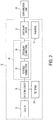
- FIG. 2 shows a block diagram of surveillance camera 12 utilizing a slip ring 24, which allows 360 degree rotation of camera 16.
- Slip ring 24 has a stationary portion with stationary electrical connections 26 and a rotating portion with rotating electrical connections 28 that are electrically connected to stationary connections 26 by rings and brushes as is known in the art.
- Camera 16 is connected to rotating circuit 30, which, in turn, is connected to rotating connections 28.
- Stationary circuit 32 is connected to stationary connections 26 and communication line 14. Although communication line 14 is shown as being connected to stationary circuit 26, some or all of the lines in communication line 14 can go directly to stationary connections 26.
- Tilt drive 20 is connected to rotating circuit 30, and pan drive 18 is connected to stationary circuit 32.
- Block 34 illustrates the stationary connectors of slip ring 24 with fourteen separate connection points labeled P1 through P14.
- the number of connection points may vary depending upon the additional features included.
- Nine of the fourteen connection points are used in this embodiment of the Ethernet implementation.
- Connection points P2 and P4 are connected respectively to lines 36P and 36N of a first twisted pair 36 of a CAT5 or other suitable cable.
- connection points P6 and P8 are connected respectively to lines 38P and 38N of a second twisted pair 38.
- One of twist pairs 36 and 38 is used for transmitting Ethernet 100BASE-T protocol signals and the other twist pair is used of receiving Ethernet 100BASE-T protocol signals.
- Connection points P1, P3, P5, P7, and P9 are connected respectively to power rails V1, V2, V3, V4, and V5 in power circuit 40, which is part of stationary circuit 32.
- the respective power rails may be different voltages utilized in camera 16, rotating circuit 30 and tilt drive 20, or two or more of the power rails may be the same voltage. The voltage can range from zero to the maximum voltage in camera 12.
- Power rails V1-V5 provide RF reference plane lines to eliminate crosstalk issues between the Ethernet data signals and other signals on the slip ring, as well as eliminating crosstalk issues between the Ethernet signals themselves.
- Each of the power rails could be equal, such as ground potential; however, then additional rings would be required in the slip ring to provide the connection points for the various voltages needed on the rotating side of surveillance camera 12.
- the five RF reference plane lines can also carry DC power and low frequency data signals as discussed below.
- Line 42 connected to connection point P10 and line 44 connected to connection point P11 allow communication with various accessories such as alarms, relays, and audio devices by, for example, by universal serial bus (USB) protocol.
- Line 46 connected to connection point P13 and line 48 connected to connection point P14 can be used with a universal asynchronous receiver/transmitter (UART) for communications across the slip ring between the stationary and rotating circuit boards.
- UART universal asynchronous receiver/transmitter
- the major portion of processing power in surveillance camera 12 is located on the rotating side. Control signals are transmitted to surveillance camera 12 through the Ethernet cable and passed through the slip ring to the main processor on the rotating board. Control signals, for example, that control the panning motor on the stationary side of surveillance camera 12, are then passed back over the UART connection on the slip ring to the stationary circuit board. Having the majority of the processing power in one location reduces the overall cost of manufacturing.
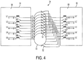
- FIG. 4 illustrates one embodiment of an implementation of the present invention.
- Nine rings of slip ring 24 is illustrated by a plurality of rings 50, labeled as connection points P1, P3, P5, P7, and P9, are respectively connected to power rails V1, V2, V3, V4, and V5 on stationary side 54 as discussed in relation to FIG. 3 and a corresponding plurality of sets of two connectors or brushes 52 contacting rings 50 and being connected to rotating side 56 and having power rails V1', V2', V3', V4', and V5' respectively on rotating side 56.
- Stationary side 54 has an RF reference plane 58 associated with stationary circuit 32
- rotating side 56 has an RF reference plane 60 associated with rotating circuit 30.
- Power rails V1-V5 and V1'-V5" provide a link between RF reference plane 58 and RF reference plan3 60.
- Lines 36P, 36N, 38P, and 38N are connected to P2, P4, P6, and P8 as discussed in relation to FIG. 3 .
- Slip ring 24 has corresponding lines on the rotating side, namely, 36P', 36N', 38P', and 38N'.
- Each leg on stationary side 54 has a ferrite coil and a capacitor connected in series between the connection point of slip ring 24 and RF reference plane 58 and the respective power rail connection located between the series connection of the ferrite coil and capacitor.
- each leg on rotating side 56 has a ferrite coil and a capacitor connected in series between the connection point of slip ring 24 and RF reference plane 60 and the respective power rail connection located between the series connection of the ferrite coil and capacitor.
- the capacitor in each leg isolates the DC voltage from respective power rail from the RF reference plane.
- the power rail is connected to the RF reference plane and the ferrite presents a large impedance to dampen the high frequency signals.
- IP PTZ camera of the present invention needs to process large bandwidth video data coming from the camera on the rotating structure and transmit that data over 100BASE-T Ethernet to the stationary structure.
- the video data from the camera is compressed before it is transmitted on the 100 BASE-T Ethernet connection, which lowers the bandwidth requirements over the Ethernet connection.
- This strategy requires sending the compressed video data through the slip ring as Ethernet packets on a 100BASE-T Ethernet transmission line, which has a power spectrum of energy up to 100MHz.
- the 100base-T Ethernet signals transmitted across the slip ring configuration of the present invention allows 720p, 1080p or higher signals since they can be compressed to 100Mbit Ethernet signals.
- the present invention conducts the data with the required signal integrity for 100BASE-T Ethernet.
- the slip ring introduces an impedance mismatch with the 100 ohm Ethernet differential line, causing ringing on the signal pulses. This can cause an increase in bit errors, or total loss of communication.
- crosstalk occurs between other signals on the slip ring and the two differential Ethernet signals, or between the two differential Ethernet signals themselves. This crosstalk can cause an increase in bit errors, or total loss of communication.
- the rings in the slip ring structure form a resonant cavity with multiple resonant frequencies.
- the quality factor or Q factor of the resonant cavity is related to how large the impedance mismatches are in the ring structure. A larger impedance mismatches causes a higher Q factor, allowing the energy to ring longer with more bit smearing.
- the resonant frequencies of the cavity depend on the size of the ring structure. Smaller structures have higher resonant frequencies.
- the present invention minimizes the impact of the ring resonant cavity, while decoupling the various signals from each other to minimize crosstalk.
- the structure is implemented on nine sequential rings of the slip ring. Four rings carry the Ethernet data signals. The remaining five rings provide damped RF reference plane lines.
- the reference plane lines in the present invention shield the crosstalk between the Ethernet lines inside the slip ring and also link the RF reference plane of the rotating circuit board with the RF reference plane of the stationary board. If the slip ring has more than nine rings, other data and power lines can be transmitted across the slip ring above or below this structure.
- the damping in the five ground reference lines burns up the RF energy trapped in the ring structure resonant cavity, lowering the Q of the resonant chamber, which quickly damps out the ringing on the Ethernet data pulses, which eliminates bit smearing.
- the damping elements in the RF reference plane lines can be surface mount ferrite devices.
- the ferrites offer a pseudo-zero Ohm path for DC power and low frequency signals, but provide a high impedance element for the high frequency RF signals. This dual purpose feature allows greater utilization of the five RF reference plane rings, thereby allowing the design to have a lower number of rings overall.
- All of the reference planes could be set at the same voltage, for example, zero volts or some other value.
- the alternating reference planes serve two purposes. The dual purpose allows the use of fewer pins, which results in a cost savings since the cost of the slip ring is proportional to the number of pins in the slip ring.
- the size of the slip ring is important because the smaller it is the higher the frequency of the signals that can be transmitted through the slip ring.
- the slip rings normally used in video surveillance domes contain two brushes for redundancy to insure that at least one of them is in contact with the respective ring of the rotor.
- a larger slip ring i.e., one with more pins, requires more time for the signals to travel around the slip ring, than a smaller slip ring.
- Damping is needed on each side of the slip ring, i.e., the rotor and the stator sides.
- the ferrite core coil device is needed to provide the dual purpose for each pin of the reference planes.
- a resistor could be used if there was no DC voltage supplied on the pin.
- the ferrite core coil device has a resistance of essentially zero for a DC signal, but it acts like a resistor at high frequencies.
- the resistive component does the damping of the ringing and transient signals in the slip ring.
- the ferrite coil burns off ringing caused by splitting of digital signal within the slip ring, since a ferrite is a super lossy inductor.
- the capacitor provides the isolation of the DC voltage on the reference plane from the ground plane. If a DC voltage is not implemented then only the resistor connected to RF reference plane is needed. In this case the resistor provides the damping effect.
Landscapes
- Engineering & Computer Science (AREA)
- Signal Processing (AREA)
- Multimedia (AREA)
- Computer Networks & Wireless Communication (AREA)
- Studio Devices (AREA)
- Closed-Circuit Television Systems (AREA)
Claims (6)
- Überwachungskamera (12) mit einem stationären Abschnitt und einem rotierenden Abschnitt und umfassend:Eine Kamera (16), die sich am rotierenden Abschnitt der Überwachungskamera (12) befindet, um Signale zu generieren, die bezeichnend für eine Szene in einem Sehfeld der Kamera (12) sind;einen ersten Schaltkreis (30), der sich am rotierenden Abschnitt der Überwachungskamera (12) befindet und elektrisch mit der Kamera (16) verbunden ist, um die von der Kamera (16) generierten Signale zu komprimieren und um die von der Kamera (16) generierten Signale in Ethernet-Protokoll-Signale umzuwandeln;einen Schleifring (24) mit einem stationären Abschnitt (54) mit einer Vielzahl elektrischer Verbindungen (26) und einem rotierenden Abschnitt (56) mit einer Vielzahl elektrischer Verbindungen (28), die mit der Vielzahl elektrischer Verbindungen (26) am stationären Abschnitt (54) des Schleifrings (24) übereinstimmen, wobei der erste Schaltkreis (30) elektrisch mit einer ersten Untergruppe der Vielzahl elektrischer Verbindungen (28) des rotierenden Abschnitts (56) des Schleifrings (24) und mit einer zweiten Untergruppe der Vielzahl elektrischer Verbindungen (28) des rotierenden Abschnitts (56) des Schleifrings (24) verbunden ist, die zum Leiten von Ethernet-Protokoll-Signalen selektiert wurden;eine HF-Bezugsebene (58), die sich am stationären Abschnitt der Überwachungskamera befindet und elektrisch mit einer ersten Untermenge der Vielzahl von elektrischen Verbindungen (26) des stationären Abschnitts (54) des Schleifrings (24) bei HF-Frequenzen verbunden ist;eine zweite Untergruppe der Vielzahl elektrischer Verbindungen (26) des stationären Abschnitts (54) des Schleifrings (24), die zum Leiten von Ethernet-Protokoll-Signalen selektiert wurde, wobei jede elektrische Verbindung der zweiten Untergruppe der Vielzahl elektrischer Verbindungen (26) des stationären Abschnitts (54) des Schleifrings (24) in Abwechslung mit jeder elektrischen Verbindung der ersten Untergruppe der Vielzahl elektrischer Verbindungen (26) des stationären Abschnitts (54) des Schleifrings (24) angeordnet ist; undeine Ferritspule, die zwischen dem Schleifring (24) und der HF-Bezugsebene (58) verbunden ist.
- Überwachungskamera (12) wie in Anspruch 1 angegeben, wobei die HF-Bezugsebene (58), die sich am stationären Abschnitt der Überwachungskamera befindet, eine stationäre HF-Bezugsebene (58) ist und ferner eine rotierende HF-Bezugsebene (60) umfasst, die sich am rotierenden Abschnitt der Überwachungskamera befindet, und wobei die erste Untergruppe der Vielzahl elektrischer Verbindungen (28) am rotierenden Abschnitt (56) des Schleifrings (24) mit der ersten Untergruppe der Vielzahl elektrischer Verbindungen (26) am stationären Abschnitt (54) des Schleifrings (24) übereinstimmt, wobei die erste Untergruppe der Vielzahl elektrischer Verbindungen (28) am rotierenden Abschnitt (56) des Schleifrings (24) mit der rotierenden HF-Bezugsebene (60) verbunden ist, die sich am rotierenden Abschnitt der Überwachungskamera bei HF-Frequenzen befindet.
- Überwachungskamera (12) wie in Anspruch 2 angegeben, wobei die Überwachungskamera (12) eine Ferritspule in jeder elektrischen Verbindung in der ersten Untergruppe der Vielzahl elektrischer Verbindungen (26) des stationären Abschnitts (54) des Schleifrings (24) und in jeder elektrischen Verbindung in der ersten Untergruppe der Vielzahl elektrischer Verbindungen (28) des rotierenden Abschnitts (56) des Schleifrings (24) umfasst.
- Überwachungskamera (12) wie in Anspruch 2 angegeben, wobei die erste Untergruppe der Vielzahl elektrischer Verbindungen (26) des stationären Abschnitts (54) des Schleifrings (24) mit einer Gleichstromversorgung verbunden sind.
- Überwachungskamera (12) wie in Anspruch 3 angegeben, wobei die erste Untergruppe der Vielzahl elektrischer Verbindungen (28) des stationären Abschnitts (54) des Schleifrings (24) mit einer Gleichstromversorgung verbunden sind.
- Überwachungskamera (12) wie in Anspruch 5 angegeben, wobei jede der Ferritspulen mit einem jeweiligen Kondensator an einer jeweiligen Anschlussstelle verbunden ist, die den elektrischen Verbindungen (26) der ersten Untergruppe der Vielzahl elektrischer Verbindungen (26) des stationären Abschnitts (54) des Schleifrings (24) oder der zweiten Untergruppe der Vielzahl elektrischer Verbindungen (26) des stationären Abschnitts (54) des Schleifrings (24) entspricht, wobei die jeweiligen Kondensatoren mit einer jeweiligen der stationären HF-Bezugsebene (58) oder der rotierenden HF-Bezugsebene (60) verbunden sind und wobei die Gleichstromversorgung eine Vielzahl von Schienen (V1, V1', V2, V2', V3, V3', V4, V4', V5, V5') umfasst, wobei die Vielzahl von Schienen jeweils zwischen der jeweiligen Ferritspule und dem Kondensator an der jeweiligen Anschlussstelle verbunden ist.
Applications Claiming Priority (2)
| Application Number | Priority Date | Filing Date | Title |
|---|---|---|---|
| US12/730,100 US8482611B2 (en) | 2010-03-23 | 2010-03-23 | Surveillance camera |
| PCT/US2011/027532 WO2011119322A1 (en) | 2010-03-23 | 2011-03-08 | Surveillance camera |
Publications (3)
| Publication Number | Publication Date |
|---|---|
| EP2583450A1 EP2583450A1 (de) | 2013-04-24 |
| EP2583450A4 EP2583450A4 (de) | 2016-07-27 |
| EP2583450B1 true EP2583450B1 (de) | 2019-11-20 |
Family
ID=44655985
Family Applications (1)
| Application Number | Title | Priority Date | Filing Date |
|---|---|---|---|
| EP11759887.0A Active EP2583450B1 (de) | 2010-03-23 | 2011-03-08 | Überwachungskamera |
Country Status (3)
| Country | Link |
|---|---|
| US (1) | US8482611B2 (de) |
| EP (1) | EP2583450B1 (de) |
| WO (1) | WO2011119322A1 (de) |
Families Citing this family (5)
| Publication number | Priority date | Publication date | Assignee | Title |
|---|---|---|---|---|
| ITMI20130777A1 (it) * | 2013-05-13 | 2014-11-14 | Conductix Wampfler S R L | Giunto elettrico rotante per la trasmissione di dati ad alta velocita' |
| ITMI20130788A1 (it) * | 2013-05-14 | 2014-11-15 | Conductix Wampfler S R L | Giunto ruotante per trasmissione dati |
| ITUB20152201A1 (it) * | 2015-07-15 | 2017-01-15 | Conductix Wampfler S R L | COLLETTORE ELETTRICO ROTANTE AD ALBERO CAVO PER ETHERNET FINO A UN Gbps |
| CN109587408A (zh) * | 2018-12-14 | 2019-04-05 | 北京大视景科技有限公司 | 一种单列式监控相机竖向安装的大场景视频融合覆盖方法 |
| CN114513603B (zh) * | 2021-12-16 | 2024-07-12 | 深圳市睿联技术股份有限公司 | 控制电路、云台摄像机、控制方法及计算机可读存储介质 |
Citations (1)
| Publication number | Priority date | Publication date | Assignee | Title |
|---|---|---|---|---|
| WO2001041316A2 (de) * | 1999-11-30 | 2001-06-07 | Schleifring Und Apparatebau Gmbh | Anordnung zur übertragung elektrischer signale zwischen bewegten teilen mit verringerter wegezahl |
Family Cites Families (20)
| Publication number | Priority date | Publication date | Assignee | Title |
|---|---|---|---|---|
| US4811082A (en) * | 1986-11-12 | 1989-03-07 | International Business Machines Corporation | High performance integrated circuit packaging structure |
| US5791903A (en) * | 1993-06-10 | 1998-08-11 | Fir Ride & Show Engineering, Inc. | Flight simulator with full roll rotation capability |
| US5453753A (en) * | 1993-09-08 | 1995-09-26 | Dorne & Margolin, Inc. | Mechanically steerable modular planar patch array antenna |
| US5805115A (en) * | 1995-08-01 | 1998-09-08 | Kevlin Corporation | Rotary microwave antenna system |
| US5934911A (en) * | 1997-04-14 | 1999-08-10 | The United States Of America As Represented By The Secretary Of The Navy | Waterproof quick disconnect slip ring device |
| JPH11329653A (ja) * | 1998-05-18 | 1999-11-30 | Star Micronics Co Ltd | スリップリングとその製造方法 |
| US6356308B1 (en) * | 1998-06-11 | 2002-03-12 | Polycom, Inc. | Device for rotatably positioning a camera or similar article about two orthogonal axes |
| US6628338B1 (en) * | 1998-07-08 | 2003-09-30 | Elbex Video Ltd. | Direct drive electric motor apparatus incorporating slip ring assembly |
| US6437656B1 (en) * | 1999-10-25 | 2002-08-20 | Electro-Tec Corp. | Broadband high data rate analog and digital communication link |
| DE10112895B4 (de) * | 2001-03-15 | 2011-09-29 | Ltn Servotechnik Gmbh | Schleifringeinheit mit einer Leiterplatte |
| US6793415B2 (en) * | 2001-11-30 | 2004-09-21 | Pelco | Slip ring assembly and method |
| US20070220741A1 (en) * | 2002-10-17 | 2007-09-27 | Ui Holding Co. | Cabeless interconnect system for pick and place machine |
| US20040169434A1 (en) * | 2003-01-02 | 2004-09-02 | Washington Richard G. | Slip ring apparatus |
| CN101023429B (zh) * | 2004-07-02 | 2010-09-01 | 斯特拉斯鲍公司 | 用于处理晶片的方法和系统 |
| US7667769B2 (en) * | 2004-07-12 | 2010-02-23 | Honeywell International Inc. | Rotatable wireless electrical coupler |
| IL164226A0 (en) * | 2004-09-22 | 2005-12-18 | Elop Electrooptics Ind Ltd | Communication link for rotating turret |
| US20060251188A1 (en) * | 2005-03-28 | 2006-11-09 | Akros Silicon, Inc. | Common-mode suppression circuit for emission reduction |
| CN101449223A (zh) * | 2006-03-16 | 2009-06-03 | 功率监视器公司 | 地下监视系统和方法 |
| US8269893B2 (en) * | 2008-05-12 | 2012-09-18 | Flir Systems, Inc. | Optical payload electrical system |
| US8120228B2 (en) * | 2008-07-15 | 2012-02-21 | Hamilton Sundstrand Corporation | Slip ring assembly |
-
2010
- 2010-03-23 US US12/730,100 patent/US8482611B2/en active Active
-
2011
- 2011-03-08 WO PCT/US2011/027532 patent/WO2011119322A1/en not_active Ceased
- 2011-03-08 EP EP11759887.0A patent/EP2583450B1/de active Active
Patent Citations (1)
| Publication number | Priority date | Publication date | Assignee | Title |
|---|---|---|---|---|
| WO2001041316A2 (de) * | 1999-11-30 | 2001-06-07 | Schleifring Und Apparatebau Gmbh | Anordnung zur übertragung elektrischer signale zwischen bewegten teilen mit verringerter wegezahl |
Also Published As
| Publication number | Publication date |
|---|---|
| EP2583450A1 (de) | 2013-04-24 |
| WO2011119322A1 (en) | 2011-09-29 |
| US8482611B2 (en) | 2013-07-09 |
| EP2583450A4 (de) | 2016-07-27 |
| US20110234792A1 (en) | 2011-09-29 |
Similar Documents
| Publication | Publication Date | Title |
|---|---|---|
| EP2583450B1 (de) | Überwachungskamera | |
| US20100073483A1 (en) | System and method for transmitting video from multiple video cameras over a single multiple pair, twisted pair cable | |
| CN110277920B (zh) | 用于在线对上提供差分数据和直流电力的电力和通信系统 | |
| JPH0685772B2 (ja) | コンピュータ軸方向断層撮影スキャナ用高速通信装置 | |
| EP3138205B1 (de) | Koaxiale datenkommunikation mit verringertem emi | |
| EP0429261A2 (de) | Gerät zur Übertragung zwischen elektronischen Systemen | |
| JP2021027530A (ja) | 信号伝送回路、信号伝送システム | |
| US8737521B2 (en) | Signal conversion during transmission of serial data streams | |
| US20230216540A1 (en) | Signal transmission device and signal transmission system | |
| CN106374306A (zh) | 一种无源同轴网络转换器及以太网供电系统 | |
| CN102075216A (zh) | 电力线通信信号隔离及耦合系统 | |
| CN208739307U (zh) | 视频信号传输系统、发送端和接收端 | |
| EP2660990B1 (de) | Asymmetrische Vollduplex-Kommunikation mit hoher Toleranz für die Merkmalimpedanz des Coaxiakabels | |
| US6744276B1 (en) | Serial digital audio data port with multiple functional configurations | |
| KR102474656B1 (ko) | 네트워크 장치 | |
| KR20140115057A (ko) | 동축케이블을 통해 압축된 고해상도 디지털 비디오 신호 전송이 가능한 폐쇄회로 텔레비전 시스템 | |
| US20180376182A1 (en) | Ip based video transmission device and broadcast system | |
| CN210007811U (zh) | 监控视频传输系统 | |
| US20190253663A1 (en) | Cable television apparatus using coupled-line directional coupler implementing high pass filter function | |
| JP2006352396A (ja) | 通信システムおよび電気機器 | |
| KR20170094904A (ko) | 인터페이스 변화 가능 케이블 | |
| JP2012070100A (ja) | ネットワーク機器 | |
| KR20140115058A (ko) | 동축케이블을 통해 압축된 고해상도 디지털 비디오 신호 전송이 가능한 폐쇄회로 텔레비전 시스템에 사용되는 네트워크 비디오 레코더 | |
| CN119452607A (zh) | 线缆 | |
| CN206332762U (zh) | 一种环通电路及数字视频录像机设备 |
Legal Events
| Date | Code | Title | Description |
|---|---|---|---|
| PUAI | Public reference made under article 153(3) epc to a published international application that has entered the european phase |
Free format text: ORIGINAL CODE: 0009012 |
|
| 17P | Request for examination filed |
Effective date: 20130116 |
|
| AK | Designated contracting states |
Kind code of ref document: A1 Designated state(s): AL AT BE BG CH CY CZ DE DK EE ES FI FR GB GR HR HU IE IS IT LI LT LU LV MC MK MT NL NO PL PT RO RS SE SI SK SM TR |
|
| DAX | Request for extension of the european patent (deleted) | ||
| RA4 | Supplementary search report drawn up and despatched (corrected) |
Effective date: 20160623 |
|
| RIC1 | Information provided on ipc code assigned before grant |
Ipc: H04N 5/232 20060101AFI20160617BHEP Ipc: H01R 39/08 20060101ALI20160617BHEP Ipc: H04B 3/32 20060101ALI20160617BHEP Ipc: G08B 13/196 20060101ALI20160617BHEP |
|
| STAA | Information on the status of an ep patent application or granted ep patent |
Free format text: STATUS: EXAMINATION IS IN PROGRESS |
|
| 17Q | First examination report despatched |
Effective date: 20180815 |
|
| GRAP | Despatch of communication of intention to grant a patent |
Free format text: ORIGINAL CODE: EPIDOSNIGR1 |
|
| STAA | Information on the status of an ep patent application or granted ep patent |
Free format text: STATUS: GRANT OF PATENT IS INTENDED |
|
| INTG | Intention to grant announced |
Effective date: 20190613 |
|
| GRAS | Grant fee paid |
Free format text: ORIGINAL CODE: EPIDOSNIGR3 |
|
| GRAA | (expected) grant |
Free format text: ORIGINAL CODE: 0009210 |
|
| STAA | Information on the status of an ep patent application or granted ep patent |
Free format text: STATUS: THE PATENT HAS BEEN GRANTED |
|
| AK | Designated contracting states |
Kind code of ref document: B1 Designated state(s): AL AT BE BG CH CY CZ DE DK EE ES FI FR GB GR HR HU IE IS IT LI LT LU LV MC MK MT NL NO PL PT RO RS SE SI SK SM TR |
|
| REG | Reference to a national code |
Ref country code: GB Ref legal event code: FG4D |
|
| REG | Reference to a national code |
Ref country code: CH Ref legal event code: EP |
|
| REG | Reference to a national code |
Ref country code: DE Ref legal event code: R096 Ref document number: 602011063504 Country of ref document: DE |
|
| REG | Reference to a national code |
Ref country code: IE Ref legal event code: FG4D |
|
| REG | Reference to a national code |
Ref country code: AT Ref legal event code: REF Ref document number: 1205496 Country of ref document: AT Kind code of ref document: T Effective date: 20191215 |
|
| REG | Reference to a national code |
Ref country code: NL Ref legal event code: MP Effective date: 20191120 |
|
| REG | Reference to a national code |
Ref country code: LT Ref legal event code: MG4D |
|
| PG25 | Lapsed in a contracting state [announced via postgrant information from national office to epo] |
Ref country code: LV Free format text: LAPSE BECAUSE OF FAILURE TO SUBMIT A TRANSLATION OF THE DESCRIPTION OR TO PAY THE FEE WITHIN THE PRESCRIBED TIME-LIMIT Effective date: 20191120 Ref country code: SE Free format text: LAPSE BECAUSE OF FAILURE TO SUBMIT A TRANSLATION OF THE DESCRIPTION OR TO PAY THE FEE WITHIN THE PRESCRIBED TIME-LIMIT Effective date: 20191120 Ref country code: BG Free format text: LAPSE BECAUSE OF FAILURE TO SUBMIT A TRANSLATION OF THE DESCRIPTION OR TO PAY THE FEE WITHIN THE PRESCRIBED TIME-LIMIT Effective date: 20200220 Ref country code: FI Free format text: LAPSE BECAUSE OF FAILURE TO SUBMIT A TRANSLATION OF THE DESCRIPTION OR TO PAY THE FEE WITHIN THE PRESCRIBED TIME-LIMIT Effective date: 20191120 Ref country code: LT Free format text: LAPSE BECAUSE OF FAILURE TO SUBMIT A TRANSLATION OF THE DESCRIPTION OR TO PAY THE FEE WITHIN THE PRESCRIBED TIME-LIMIT Effective date: 20191120 Ref country code: GR Free format text: LAPSE BECAUSE OF FAILURE TO SUBMIT A TRANSLATION OF THE DESCRIPTION OR TO PAY THE FEE WITHIN THE PRESCRIBED TIME-LIMIT Effective date: 20200221 Ref country code: NO Free format text: LAPSE BECAUSE OF FAILURE TO SUBMIT A TRANSLATION OF THE DESCRIPTION OR TO PAY THE FEE WITHIN THE PRESCRIBED TIME-LIMIT Effective date: 20200220 Ref country code: NL Free format text: LAPSE BECAUSE OF FAILURE TO SUBMIT A TRANSLATION OF THE DESCRIPTION OR TO PAY THE FEE WITHIN THE PRESCRIBED TIME-LIMIT Effective date: 20191120 Ref country code: ES Free format text: LAPSE BECAUSE OF FAILURE TO SUBMIT A TRANSLATION OF THE DESCRIPTION OR TO PAY THE FEE WITHIN THE PRESCRIBED TIME-LIMIT Effective date: 20191120 |
|
| PG25 | Lapsed in a contracting state [announced via postgrant information from national office to epo] |
Ref country code: HR Free format text: LAPSE BECAUSE OF FAILURE TO SUBMIT A TRANSLATION OF THE DESCRIPTION OR TO PAY THE FEE WITHIN THE PRESCRIBED TIME-LIMIT Effective date: 20191120 Ref country code: IS Free format text: LAPSE BECAUSE OF FAILURE TO SUBMIT A TRANSLATION OF THE DESCRIPTION OR TO PAY THE FEE WITHIN THE PRESCRIBED TIME-LIMIT Effective date: 20200320 Ref country code: RS Free format text: LAPSE BECAUSE OF FAILURE TO SUBMIT A TRANSLATION OF THE DESCRIPTION OR TO PAY THE FEE WITHIN THE PRESCRIBED TIME-LIMIT Effective date: 20191120 |
|
| PG25 | Lapsed in a contracting state [announced via postgrant information from national office to epo] |
Ref country code: AL Free format text: LAPSE BECAUSE OF FAILURE TO SUBMIT A TRANSLATION OF THE DESCRIPTION OR TO PAY THE FEE WITHIN THE PRESCRIBED TIME-LIMIT Effective date: 20191120 |
|
| PGFP | Annual fee paid to national office [announced via postgrant information from national office to epo] |
Ref country code: FR Payment date: 20200325 Year of fee payment: 10 |
|
| PG25 | Lapsed in a contracting state [announced via postgrant information from national office to epo] |
Ref country code: PT Free format text: LAPSE BECAUSE OF FAILURE TO SUBMIT A TRANSLATION OF THE DESCRIPTION OR TO PAY THE FEE WITHIN THE PRESCRIBED TIME-LIMIT Effective date: 20200412 Ref country code: EE Free format text: LAPSE BECAUSE OF FAILURE TO SUBMIT A TRANSLATION OF THE DESCRIPTION OR TO PAY THE FEE WITHIN THE PRESCRIBED TIME-LIMIT Effective date: 20191120 Ref country code: DK Free format text: LAPSE BECAUSE OF FAILURE TO SUBMIT A TRANSLATION OF THE DESCRIPTION OR TO PAY THE FEE WITHIN THE PRESCRIBED TIME-LIMIT Effective date: 20191120 Ref country code: RO Free format text: LAPSE BECAUSE OF FAILURE TO SUBMIT A TRANSLATION OF THE DESCRIPTION OR TO PAY THE FEE WITHIN THE PRESCRIBED TIME-LIMIT Effective date: 20191120 Ref country code: CZ Free format text: LAPSE BECAUSE OF FAILURE TO SUBMIT A TRANSLATION OF THE DESCRIPTION OR TO PAY THE FEE WITHIN THE PRESCRIBED TIME-LIMIT Effective date: 20191120 |
|
| REG | Reference to a national code |
Ref country code: AT Ref legal event code: MK05 Ref document number: 1205496 Country of ref document: AT Kind code of ref document: T Effective date: 20191120 |
|
| REG | Reference to a national code |
Ref country code: DE Ref legal event code: R097 Ref document number: 602011063504 Country of ref document: DE |
|
| PG25 | Lapsed in a contracting state [announced via postgrant information from national office to epo] |
Ref country code: SM Free format text: LAPSE BECAUSE OF FAILURE TO SUBMIT A TRANSLATION OF THE DESCRIPTION OR TO PAY THE FEE WITHIN THE PRESCRIBED TIME-LIMIT Effective date: 20191120 Ref country code: SK Free format text: LAPSE BECAUSE OF FAILURE TO SUBMIT A TRANSLATION OF THE DESCRIPTION OR TO PAY THE FEE WITHIN THE PRESCRIBED TIME-LIMIT Effective date: 20191120 |
|
| PLBE | No opposition filed within time limit |
Free format text: ORIGINAL CODE: 0009261 |
|
| STAA | Information on the status of an ep patent application or granted ep patent |
Free format text: STATUS: NO OPPOSITION FILED WITHIN TIME LIMIT |
|
| 26N | No opposition filed |
Effective date: 20200821 |
|
| PG25 | Lapsed in a contracting state [announced via postgrant information from national office to epo] |
Ref country code: MC Free format text: LAPSE BECAUSE OF FAILURE TO SUBMIT A TRANSLATION OF THE DESCRIPTION OR TO PAY THE FEE WITHIN THE PRESCRIBED TIME-LIMIT Effective date: 20191120 |
|
| REG | Reference to a national code |
Ref country code: CH Ref legal event code: PL |
|
| PG25 | Lapsed in a contracting state [announced via postgrant information from national office to epo] |
Ref country code: AT Free format text: LAPSE BECAUSE OF FAILURE TO SUBMIT A TRANSLATION OF THE DESCRIPTION OR TO PAY THE FEE WITHIN THE PRESCRIBED TIME-LIMIT Effective date: 20191120 Ref country code: SI Free format text: LAPSE BECAUSE OF FAILURE TO SUBMIT A TRANSLATION OF THE DESCRIPTION OR TO PAY THE FEE WITHIN THE PRESCRIBED TIME-LIMIT Effective date: 20191120 Ref country code: PL Free format text: LAPSE BECAUSE OF FAILURE TO SUBMIT A TRANSLATION OF THE DESCRIPTION OR TO PAY THE FEE WITHIN THE PRESCRIBED TIME-LIMIT Effective date: 20191120 |
|
| REG | Reference to a national code |
Ref country code: BE Ref legal event code: MM Effective date: 20200331 |
|
| PG25 | Lapsed in a contracting state [announced via postgrant information from national office to epo] |
Ref country code: LU Free format text: LAPSE BECAUSE OF NON-PAYMENT OF DUE FEES Effective date: 20200308 |
|
| PG25 | Lapsed in a contracting state [announced via postgrant information from national office to epo] |
Ref country code: IE Free format text: LAPSE BECAUSE OF NON-PAYMENT OF DUE FEES Effective date: 20200308 Ref country code: CH Free format text: LAPSE BECAUSE OF NON-PAYMENT OF DUE FEES Effective date: 20200331 Ref country code: LI Free format text: LAPSE BECAUSE OF NON-PAYMENT OF DUE FEES Effective date: 20200331 |
|
| PG25 | Lapsed in a contracting state [announced via postgrant information from national office to epo] |
Ref country code: BE Free format text: LAPSE BECAUSE OF NON-PAYMENT OF DUE FEES Effective date: 20200331 |
|
| REG | Reference to a national code |
Ref country code: DE Ref legal event code: R081 Ref document number: 602011063504 Country of ref document: DE Owner name: PELCO, INC., FRESNO, US Free format text: FORMER OWNER: PELCO, INC., CLOVIS, CALIF., US Ref country code: DE Ref legal event code: R082 Ref document number: 602011063504 Country of ref document: DE Representative=s name: SCHUMACHER & WILLSAU PATENTANWALTSGESELLSCHAFT, DE |
|
| PG25 | Lapsed in a contracting state [announced via postgrant information from national office to epo] |
Ref country code: FR Free format text: LAPSE BECAUSE OF NON-PAYMENT OF DUE FEES Effective date: 20210331 |
|
| PG25 | Lapsed in a contracting state [announced via postgrant information from national office to epo] |
Ref country code: TR Free format text: LAPSE BECAUSE OF FAILURE TO SUBMIT A TRANSLATION OF THE DESCRIPTION OR TO PAY THE FEE WITHIN THE PRESCRIBED TIME-LIMIT Effective date: 20191120 Ref country code: MT Free format text: LAPSE BECAUSE OF FAILURE TO SUBMIT A TRANSLATION OF THE DESCRIPTION OR TO PAY THE FEE WITHIN THE PRESCRIBED TIME-LIMIT Effective date: 20191120 Ref country code: CY Free format text: LAPSE BECAUSE OF FAILURE TO SUBMIT A TRANSLATION OF THE DESCRIPTION OR TO PAY THE FEE WITHIN THE PRESCRIBED TIME-LIMIT Effective date: 20191120 |
|
| PG25 | Lapsed in a contracting state [announced via postgrant information from national office to epo] |
Ref country code: MK Free format text: LAPSE BECAUSE OF FAILURE TO SUBMIT A TRANSLATION OF THE DESCRIPTION OR TO PAY THE FEE WITHIN THE PRESCRIBED TIME-LIMIT Effective date: 20191120 |
|
| REG | Reference to a national code |
Ref country code: DE Ref legal event code: R079 Ref document number: 602011063504 Country of ref document: DE Free format text: PREVIOUS MAIN CLASS: H04N0005232000 Ipc: H04N0023600000 |
|
| P01 | Opt-out of the competence of the unified patent court (upc) registered |
Effective date: 20230529 |
|
| REG | Reference to a national code |
Ref country code: DE Ref legal event code: R082 Ref document number: 602011063504 Country of ref document: DE Representative=s name: PUSCHMANN BORCHERT KAISER KLETTNER PATENTANWAE, DE Ref country code: DE Ref legal event code: R082 Ref document number: 602011063504 Country of ref document: DE Representative=s name: PATCARE PATENTANWAELTE PARTNERSCHAFT MBB, DE |
|
| PGFP | Annual fee paid to national office [announced via postgrant information from national office to epo] |
Ref country code: GB Payment date: 20260219 Year of fee payment: 16 |
|
| PGFP | Annual fee paid to national office [announced via postgrant information from national office to epo] |
Ref country code: DE Payment date: 20260219 Year of fee payment: 16 |
|
| PGFP | Annual fee paid to national office [announced via postgrant information from national office to epo] |
Ref country code: IT Payment date: 20260219 Year of fee payment: 16 |