EP2583244B1 - Method of determination of access areas from 3d patient images - Google Patents
Method of determination of access areas from 3d patient images Download PDFInfo
- Publication number
- EP2583244B1 EP2583244B1 EP11764608.3A EP11764608A EP2583244B1 EP 2583244 B1 EP2583244 B1 EP 2583244B1 EP 11764608 A EP11764608 A EP 11764608A EP 2583244 B1 EP2583244 B1 EP 2583244B1
- Authority
- EP
- European Patent Office
- Prior art keywords
- image
- bone
- arthroscopic
- portal
- coordinate system
- Prior art date
- Legal status (The legal status is an assumption and is not a legal conclusion. Google has not performed a legal analysis and makes no representation as to the accuracy of the status listed.)
- Active
Links
Images


Classifications
-
- A—HUMAN NECESSITIES
- A61—MEDICAL OR VETERINARY SCIENCE; HYGIENE
- A61B—DIAGNOSIS; SURGERY; IDENTIFICATION
- A61B1/00—Instruments for performing medical examinations of the interior of cavities or tubes of the body by visual or photographical inspection, e.g. endoscopes; Illuminating arrangements therefor
- A61B1/313—Instruments for performing medical examinations of the interior of cavities or tubes of the body by visual or photographical inspection, e.g. endoscopes; Illuminating arrangements therefor for introducing through surgical openings, e.g. laparoscopes
- A61B1/317—Instruments for performing medical examinations of the interior of cavities or tubes of the body by visual or photographical inspection, e.g. endoscopes; Illuminating arrangements therefor for introducing through surgical openings, e.g. laparoscopes for bones or joints, e.g. osteoscopes, arthroscopes
-
- G—PHYSICS
- G06—COMPUTING; CALCULATING OR COUNTING
- G06T—IMAGE DATA PROCESSING OR GENERATION, IN GENERAL
- G06T7/00—Image analysis
- G06T7/70—Determining position or orientation of objects or cameras
- G06T7/73—Determining position or orientation of objects or cameras using feature-based methods
- G06T7/75—Determining position or orientation of objects or cameras using feature-based methods involving models
-
- A—HUMAN NECESSITIES
- A61—MEDICAL OR VETERINARY SCIENCE; HYGIENE
- A61B—DIAGNOSIS; SURGERY; IDENTIFICATION
- A61B34/00—Computer-aided surgery; Manipulators or robots specially adapted for use in surgery
- A61B34/10—Computer-aided planning, simulation or modelling of surgical operations
-
- G—PHYSICS
- G06—COMPUTING; CALCULATING OR COUNTING
- G06T—IMAGE DATA PROCESSING OR GENERATION, IN GENERAL
- G06T2207/00—Indexing scheme for image analysis or image enhancement
- G06T2207/10—Image acquisition modality
- G06T2207/10072—Tomographic images
-
- G—PHYSICS
- G06—COMPUTING; CALCULATING OR COUNTING
- G06T—IMAGE DATA PROCESSING OR GENERATION, IN GENERAL
- G06T2207/00—Indexing scheme for image analysis or image enhancement
- G06T2207/30—Subject of image; Context of image processing
- G06T2207/30004—Biomedical image processing
- G06T2207/30008—Bone
Definitions
- the invention relates to the field of computer assisted surgery, and more particularly to a method for determining portals for arthroscopy.
- Femoro Acetabular Impingement is a pathology that can result from a decreased femoral head-neck offset (cam effect), an overgrowth of the bony acetabulum (pincer effect), excessive acetabular retroversion or excessive femoral anteversion, or a combination of these deformities.
- the cam impingement is generally characterized by a bone overgrowth located at the antero-superior aspect of the femur head-neck junction, which destructures the spherical shape of the femur head.
- the pincer impingement is generally characterized by an overcoverage located at the anterior aspect of the acetabulum rim.
- the correct and full diagnosis of this pathology is not easy to determine, especially when dealing with subtle deformities.
- Standard radiographic X-rays are used for the initial diagnosis and then three dimensional (3D) Computed Tomography (CT) scans or Magnetic Resonance Imaging (MRI) exams are generally performed in case of suspected FAI pathology.
- CT Computed Tomography
- MRI Magnetic Resonance Imaging
- the processing of the 3D image remains a laborious manual task which cannot ensure accuracy and reproducibility, potentially misleading the diagnosis or the surgical indication.
- 3D information can be extracted from such exams, the reconstructed bone volumes remain static and cannot predict with reliability the exact location of the impingement which occurs during the mobilization of the hip.
- the surgical treatment of FAI aims at restoring a normal spherical shape to the femur head at the level of the bony cam lesion and restoring a normal coverage rate of the acetabular rim at the level of the pincer lesion, by removing the excess of bone.
- the result of this bony reshaping is the restoration of a greater range of motion of the hip, without impingement.
- the open surgical approach had initially been adopted since it provides a full exposure of the bone and direct access to the anatomy to be treated.
- arthroscopic treatment of FAI has been explored in the last decade, which requires the use of an endoscopic camera and specific small instruments that can pass through various types of canulas.
- Advantages include minimally invasive access to the hip joint, peripheral compartments, and associated soft tissues.
- arthroscopy allows for a dynamic, intra-operative assessment and correction of the offending lesions.
- due to the depth of the joint and the reduced visibility and access, theses hip arthroscopy procedures are difficult to perform and not all surgeons feel comfortable about adopting the technique.
- a surgical navigation system includes a localization device, at least one tracker and a processor.
- One or more emitters are embedded in either the localization device or the tracker.
- One or more receivers are embedded in the other of the localization device or the tracker to detect the signals emitted by the emitters.
- the signals are transmitted to the processor, which computes localization data to detect the relative position and orientation of the tracker and localization device.
- the localization device of a surgical navigation system can use several types of signals: optical, electromagnetic, ultrasonic, or other, depending on the most appropriate technology to be compatible with the surgical environment.
- passive reflective markers constitute trackers that are observed by a pair of stereoscopic camera that constitute the localization device.
- emitters are made of infra-red LEDs and they are observed by at least three linear CCD cameras having cylindrical lenses.
- one or several emitter coils constitute the localization device and several miniature coils constitute the trackers that can be attached to instruments or directly to the bones; miniature coils can track the full six degrees of freedom of a solid or reduced versions can track only five degrees of freedom (position of a point and orientation of an axis).
- at least one tracker is rigidly attached to the patient anatomy which is undergoing the surgical procedure, for example a bone, usually with a broach or pin mechanism.
- at least one tracker is attached to a surgical instrument, for which the part to be tracked is calibrated, for example the tip of a drill.
- the localization device and the tracker are linked to the computer processor on which software is running to record trackers positions, register patient data and compute instruments trajectories.
- the patient data may be obtained from several sources, either from pre-operative data such as 3D image from computer tomography (CT) scans or magnetic resonance (MR) exams for example, or from intra-operative digitization of the anatomy such as bone surface points digitization to build a bone surface model from statistical deformation of a reference model.
- CT computer tomography
- MR magnetic resonance
- the software of the navigation system processes patient data and according to the specific goal will generally compute an optimized trajectory or position for a surgical instrument, a cutting jig for example.
- Intra-operatively the tracked instrument needs to be localized relatively to the patient anatomy. If the patient data is directly obtained from intra-operative anatomy digitization then both the patient reference system and the instrument reference system are known in the same coordinates system via the localization device, and the instrument can be directly navigated relatively to the patient data.
- MIS minimally invasive
- intra-operative images such as fluoroscopy X-rays or endoscopic images are used to obtain intra-operative data.
- 2D image information is generally not sufficient to achieve the required accuracy in three dimensions, and a pre-operative 3D image is usually required.
- an intermediate process needs to be performed before the navigation of the instrument relatively to the patient data. It is called registration, in order to match the pre-operative data of the patient to the reference system of the actual patient installed for surgery.
- This known procedure can be performed with a variety of different methods. It requires the acquisition of intra-operative patient data to be matched with the pre-operative patient data.
- the registration process can be based on specific paired points which are anatomical or fiducial points identified in the pre-operative data and matched with the same points digitized intra-operatively.
- the registration can also be based on image similarity measures between pre-operative image volume and intra-operative fluoroscopic image, using maximization of entropy, mutual information, or correlation coefficients for example.
- a process is generally applied to the data to identify targets that can be anatomical structures, determine instruments trajectories or bony cutting planes or axes for example.
- the aim of the registration process is to be able to track the surgical instrument in the actual surgical site in accordance to a pre-operatively defined target.
- the surgical instrument can be also attached to the extremity of a robot or a haptic device that constrains the motions of the surgeon tool.
- the patent application US2003/0109780 describes the planning of entry ports for robotic surgery on pre-operative 3D patient chest data.
- the invention provides a method for automatically determining at least one pre-operative portal for arthroscopy from acquired pre-operative medical images of a bone of a patient, the method comprising the following steps:
- Another object of the invention is a method for simulating arthroscopic images before surgery, comprising the steps of determining at least one pre-operative portal by the method according to claim 1, placing a virtual arthroscope at said pre-operative portal and computing a virtual arthroscopic image of the surgical area obtained by the virtual arthroscope.
- the pre-operative portal is preferably an arthroscopic portal defined by a tool entry point and a direction.
- the method comprises inferring through the transform critical areas containing vessels or nerves from the model coordinate system to the bone reference coordinate system.
- the transform may be determined through analytical and/or geometric process.
- the transform may be determined as a continuous function from the model coordinate system to the bone reference coordinate system.
- the transform may be determined through a non-rigid image-to-image or surface-to-surface registration algorithm.
- the pre-operative portal may be an arthroscopic portal defined by a tool entry point and a direction, and a virtual arthroscopic image may thus be constructed from the arthroscopic portal.
- Said method may further comprise generating planning information and superimposing the planning information onto the virtual arthroscopic image.
- the planning information is a color map representing amount of bone to be removed.
- the planning information is a projection of an optimal surface to be built onto the bone.
- said method may further comprise generating an adjusted virtual arthroscopic image by adjusting and registering the virtual arthroscopic image to real arthroscopic image of the bone.
- Registering the virtual arthroscopic image to real arthroscopic image of the bone preferably comprises the following steps:
- the method may further comprise generating planning information and generating a superimposed image by superimposing the planning information onto the adjusted virtual arthroscopic image.
- the method comprises generating planning information and superimposing planning information and the adjusted virtual arthroscopic image onto the real arthroscopic image of the bone.
- the method may advantageously comprise displaying the superimposed image and the real arthroscopic image side by side.
- the method comprises the manual modification of the pre-operative portal around its initial computed position.
- the purpose of the invention is to provide a method and a device for helping the user to accurately and automatically determine portals and safe access areas for arthroscopic procedures using pre-operative 3D image and also for planning relevant arthroscopic images that can be used during the surgery in addition to target data. It is intended to provide a very simple and fast rehearsal tool or simulation of surgery. Moreover, the invention provides help for the surgeon to locate and use the predefined portals and safe access areas during surgery.
- an example of the method of the invention is described for the femur and pelvis bones during a hip arthroscopy procedure in the case of a FAI indication, but it can be applied to any other human or animal bone for which itself or the adjacent ligaments, tendons and muscles present an abnormality and for which an arthroscopic procedure has to be performed, for instance in the case of knee anterior cruciate ligament repairs or shoulder rotator cuff repairs.
- an external 3D surface model S of the bone showing the cortical surface or the cartilage surface is reconstructed.
- This can be achieved using a variety of methods, for instance by using conventional segmentation techniques with simple thresholding followed by conventional mathematical morphology algorithms. It is possible to use the well known marching cube algorithms or the dividing cube algorithms.
- the most elementary method is the delineation of contours using a mouse and active contouring using snakes.
- Snakes are curves like spline or Bezier curves controlled by a few control points on which a function is applied that generates forces in the direction of image gradients for instance, so that locally it will fit contours and globally it needs assistance from the user to displace the control points.
- anatomical landmarks points and axis
- FIGURE 1 in the case of the femur, the center of the femoral head H and the radius R of the sphere that best approximate the femoral head have been determined in a step that precedes the use of the method of the invention.
- an axis AX that best approximates the neck axis has been determined. More precisely, the true neck axis AX1 does not pass necessarily through the head center H and therefore we define the neck axis AX as the axis passing through H and parallel to the true neck axis.
- the knee center K of the femur has been determined on the 3D image, together with a medio-lateral axis ML that can be the line joining the epicondyles E1 and E2 or another definition ML' is the line joining the most posterior points P1 and P2.
- An elementary method for determining those landmarks is simply an interactive delineation on the 3D image using a mouse which is commonly performed for difficult cases. But automatic method can also be applied using dedicated algorithms for detection of a sphere, a neck, a landmark point and the like.
- the invention can be implemented whatever the method for obtaining the anatomical landmarks is.
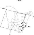
- a bone reference coordinate system Rbone (OF, X F , Y F , Z F ) is determined for the femur according to the following method, as illustrated in FIGURE 2 .
- the origin O F of the femur reference coordinate system is the point H.
- the X F direction is the line (HK) between the hip center H and the knee center K.
- the normalized vectorial product between X F and AX defines the vector Z F .
- the vectorial product between Z F and X F defines the vector Y F .
- the femur reference coordinate system Rbone is then entirely defined.
- the same method is applied but the neck axis AX is replaced by the medio-lateral axis ML or ML'.
- the pelvis bone is constructed from 4 anatomical landmarks: the pubis symphysis PS, the left and right antero-superior iliac spines ASIS L and ASIS R , and the center of the acetabulum sphere A.
- Our protocol requires the acquisition of a few CT slices at the level of the iliac spines, which is usually contained in a separate file in a standard DICOM format (which is well known in the medical field) but with the same coordinates for all files that constitute sub-volumes of the 3D image.
- Our process identifies the ASIS L and ASIS R points automatically.
- the detection of the most anterior points on the left and right side of the 3D image is performed by searching those points in the 3D image.
- the pubic symphysis PS can also be automatically detected, by searching for a plane passing through ASIS L and ASIS R and rotating around the axis made by those 2 points until it hits the most anterior point PS outside of a vicinity of two centimeters around ASIS L and ASIS R .
- the acetabulum sphere centered in the point A is computed from an initial estimate which comes from the femoral head sphere H computed earlier for the femur.
- the femoral head sphere can be dilated by an average cartilage thickness of 5mm, and then closest surface points are searched this time in the pelvis 3D surface forming a new cloud of points.
- a new best fitting sphere is computed from this new cloud of points.
- the center of the new best fitting sphere defines the acetabulum center point A.
- the pelvis reference coordinate system is constructed in the following manner: the origin is the center point of the acetabulum sphere A, the Y P axis is defined as the line passing through both iliac spines, the X P axis is defined as the line orthogonal to the iliac spines axis and passing through the public symphysis PS, and the Z P axis is constructed as the vector product of X P by Y P .
- Rbone (A, X P , Y P , Z P ) determines the pelvis reference coordinate system.
- the next step is to assign some pre-determined access elements to the patient data.
- a data base is built to store the position of pre-determined access elements in the coordinate system of a 3D model.
- the 3D model is referred to as an atlas, it can be built manually but this is difficult.
- a 3D image ATLAS of a particular reference person that is representative of the population is selected.
- a model coordinate system Ratlas (OF',X F' ,Y F' ,Z F' ) is built and attached to the bone surface model built from the particular reference person image using exactly the same method described above for the patient.
- Access elements can be portals or critical areas. They constitute a database DB of access elements. Such database DB can be built using the knowledge of experts and it can be modified according to the evolution of the knowledge of experts.
- the database contains a pattern of portals.
- a pattern of portals is a list of N elements where each element (G',D') defines a target point G' and a direction D' that are determined using specific geometric rules.
- the pattern of portals is a list of 3 elements (G' Ant , D' Ant ), (G' Ant-Lat , D' Ant-Lat ), (G' Post-Lat , D' Post-Lat ) where G' Ant is the target point of the anterior portal and D' Ant is the direction vector of the anterior portal.
- G' Ant-Lat is the target point of the anterior lateral portal and D' Ant-Lat is the direction vector of the anterior lateral portal.
- G' Post-Lat is the target point of the posterior lateral portal and D' Post-Lat is the direction vector of the posterior lateral portal.
- FIGURE 4 and FIGURE 5 An example of a specific pattern of portals that has been built by medical experts is described hereafter, as represented on FIGURE 4 and FIGURE 5 . It is only one example and the invention does not aim at recommending one pattern versus another one.
- all three portals target points G' Ant , G' Ant-Lat , G' Post-Lat are lying in an axial plane P' Ax parallel to the (Y' F Z' F ) plane of the femoral model coordinate system and passing through the superior extremity of the greater trochanter.
- All direction vector D'i are defined by a pair of angles ( ⁇ 'i, ⁇ 'i) where ⁇ 'i is the angle measured in the sagittal plane P' Sag , and ⁇ 'i is the angle measured in the axial plane P' Ax , relatively to the axis Z' F .
- G' Post-Lat is defined as the intersection of the plane P' Ax and a line of direction vector D' Post-Lat tangent to the posterior aspect of the greater trochanter.
- a pattern of portals can contain one or two or three or more than elements.
- portals can be defined relatively to acetabulum model coordinate system, or from a combination of criteria in both the femur and the acetabulum model coordinate systems.
- the next step of the method is to infer the pre-determined access elements built in the atlas to the patient.
- This is achieved by building a transform [T] between Rbone and Ratlas. Since the same method is used for determining Ratlas and Rbone from their respective 3D image, the transform [T] can be assigned to the identity transform. However, in a preferred embodiment, a size factor is assigned in order to take into account significant variations between the atlas and the patient.
- R for the patient and R' for the atlas.
- the ratio value R/R' is computed and stored as a factor k.
- the target points that are lying on the femoral head surface of the atlas are transformed in points lying on the femoral head surface on the patient bone. It is then assumed that landmark points are transformed into landmark points that are in the vicinity of what should be their real value.
- the direction vectors D remain identical to the vectors D' if they are normalized.
- the pattern of portals of the atlas is inferred to the patient coordinate system Rbone in a very simple, fast, automatic and robust manner. A non expert user can thus benefit from a determination of optimal portals on the basis of portal patterns which were designed by an expert.
- the transform [T] can be more complex than a scaling transform.
- a non-rigid transform [T] is built as a continuous function from Ratlas to Rbone in order to match the 3D bone surface model or directly the 3D image of the patient to respectively the model or image of the atlas. Standard non-rigid image-to-image or surface-to-surface registration algorithms can be used.
- the global transform from the selected predefined atlas Ratlas to the actual patient Rbone can be achieved by calculation of a deformable smooth and minimal transform between the surfaces of the predefined model and the surfaces extracted from patient data, using well known elastic surface matching algorithms.
- one technique consists in calculating the deformation of a 3D mesh that is applied to the volume of the predefined model in order to match the patient model.
- the method is initialized using the identity matrix since Rbone and Ratlas have been determined in a similar manner and using identical definitions. Then the sum of squares of distances between the atlas surface model and the patient surface model is minimized using Levenberg-Marquardt algorithm, which results in determining displacement vectors of the mesh.
- the 3D image of the atlas and the 3D image of the patient are registered directly by maximizing an image similarity function built from the mutual entropy, the joint correlation coefficient or other well known criteria described in the image registration literature. The advantage of this embodiment is to infer anatomical landmarks anywhere from the atlas and still maintain an accurate position of the result.
- Another characteristic element that can be inferred by this method is an area with potential risk of presence of blood vessels in the arthroscopic site.
- retinacular vessels are irrigating the bony structures lying in some precise posterior area of the femoral head neck junction. This area must be avoided during milling of the femoral head-neck area in arthroscopic procedures.
- the method for determining this area consists in estimating a center point V' of the critical area and a radius R' V that defines the extent of the critical area in Ratlas. It determines a virtual sphere centered around V' and with a radius R'v for which the intersection with the bone surface defines the surface patch of the critical area.
- This area is defined in the Atlas model coordinate system Ratlas.
- any geometric construction rule known to identify anatomical characteristic elements can be used to infer targets, critical areas, access areas in the femur or in the pelvis reference coordinate system using the method defined above. It is sufficient that characteristic access elements are defined by geometric rules in the model coordinate system attached to an atlas.
- the portals and critical areas determined using the method mentioned above constitute a reliable basis that any user can consider to be an initial determination of the portals.
- the method described above is useful to provide a rehearsal and training tool to the users, including the surgeon, the medical staff, the students or even the patient. Indeed, once the portals have been determined in the 3D image, simulated arthroscopic images are now computed to provide the user with a theoretical vision of what will be seen by the arthroscope if the arthroscope was positioned precisely at the portals positions.
- a real arthroscope 1 produces a real arthroscopic image 2.
- a virtual model 4 is then created to describe the existing arthroscope 1. It is assumed that the arthroscope is known in its entire geometry. Conventional calibration methods can be used to measure the parameters of an arthroscope. As shown in FIGURE 9 , the extremity of the arthroscope is E and its axis direction is DE.
- the optical axis direction AD is supposed to be known, it is not necessarily coincident with the arthroscope mechanical axis DE.
- the angle of visibility of the arthroscope AA is also known.
- the mechanical axis DE of the virtual arthroscope 4 is aligned with the portal direction D defined above.
- the distance d can be a variable parameter that represents a simulation of the distance between the arthroscope extremity and the bone.
- a vertical direction U of the arthroscopic image is chosen arbitrarily.
- the user often turns a wheel on the arthroscope to vary the vertical direction U of the arthroscopic image. It is then possible to compute a virtual arthroscopic image 3 of the bone corresponding to this configuration from the 3D image using conventional ray-tracing visualization methods applied to the surface model of the bone S.
- the virtual arthroscopic image shows a simulation of what the arthroscope would see, including a projection of the bone surface model and any other features attached to the model.
- the light source is only one and it is emanating from the extremity E which makes simple and efficient lightening computations.
- the user can play with the distance parameter d which acts like a zoom and with a rotation around the axis DE to simulate what will be visible and check that a good visibility of the surgical area has been obtained. It provides a useful training and educational tool but also a rehearsal tool before surgery.
- surgical target areas are defined in the patient images.
- a surgical target is a resection volume that needs to be milled to recreate a normal surface of the bone.
- the method for determining the surgical target as an optimal surface is not in the scope of this invention since it is specific to the procedure and the optimization criteria. It is assumed that an optimal 3D resection volume has been defined, and which can be represented by a color map 5 with different colors corresponding to depth of bone to be milled, for instance green between 0 and 1mm, yellow for depth between 1 and 2mm, orange between 2 and 3mm and the like. This color map 5 is superimposed to the bone surface model S.
- the virtual arthroscopic image 3 contains not only the projection of the surface model but also a projection of the color map 5. Therefore, the user can check that the portal placement leads to a good visualization of the surgical target area. This process is repeated for all portals.
- the portal placements are modified interactively by the user using a mouse, around their initial position. It is then always possible to switch back to the initial position if erroneous displacements have been performed since the selection of portals is a very sensitive procedure.
- the method described above can be used for calculating and displaying the virtual images before the surgery as a rehearsal tool, on a desktop in the surgeon office. But the memory of this simulation is then partially lost when the surgeon goes to the operating room.
- the virtual arthroscopic image 3 is displayed side by side to the real arthroscopic image 2, during a surgical procedure. Two dedicated monitors are used to display side by side the real and the virtual arthroscopic images.
- the user can have knowledge of the portal that corresponds to each virtual image since the portal direction D and target G can be displayed on one of the monitors as a reminder. When the user places a portal, it is recommended that the user places the portal according to the selected position which is displayed on the monitor.
- the visualization of the surgical target area on a virtual arthroscopic image which is quite similar to the real arthroscopic image brings significant information to the surgeon during the operation.
- the difference between the real and the virtual image can be interpreted mentally by the user and the user can try to move the real arthroscope until it matches the virtual arthroscopic image.
- a device is then added to determine a displacement of the virtual arthroscope 4.
- Such device can be any device such as a mouse, a joystick, a touch pad or buttons on touch screen, in order to generate a motion in two directions to create rotations of the virtual arthroscope around its initial axis and another motion in two directions to create a translation of the virtual arthroscopic image 3 in the image plane and another motion to generate a zoom effect.
- the rotation around the center of the image can be achieved on the real athroscopic image by using the wheel that controls the image rotation U on any conventional arthroscope.
- the user can manipulate those buttons if they are sterile, under sterile transparent draping for instance, or the user can ask an assistant to adjust those parameters for matching the virtual arthroscopic image with the real arthoscopic image whilst the real arthroscope stays still.
- the adjustment of the virtual and the real arthroscopic images is automatically performed.
- the real arthroscopic image is digitized in real time in a computer video frame grabber.
- the real arthroscopic image and the virtual arthroscopic image are quite similar thanks to the method described above. This is extremely important since it constitutes a good initial position for image registration.
- a conventional 3D to 2D image registration algorithm can then be used to adjust the position and orientation parameters of the virtual arthroscope until the real arthroscopic image and the virtual arthroscopic image have an optimal criterion such as entropy or mutual information. Those algorithms are prone to significant and frequent errors if the initial position of registration is too far and the images are too much different between themselves.
- the invention creates means to generate an initial registration transform that is in the convergence domain of most standard 3D to 2D registration algorithms.
- criteria based on a similarity function between the real and the virtual images are optimized according to the six parameters that define the position of the virtual arthroscope with respect to the coordinate system of the 3D image.
- Such criteria can be mutual information, the entropy, the correlation coefficient or the like.
- Having a good initial transform between the real and virtual images is also important to make the process fast enough so that the virtual image can track the real image in real time. Otherwise, the algorithm registers the images but lasts so long that meanwhile the user has moved the arthroscope and, thus, the real and virtual images never register together.
- the resulting position is used as an initial position for the second registration and the method is iterated. If the tracking is lost, the initial transform computed using the method defined above is used again as a home position.
- the initial transform computed using the method defined above is used again as a home position.
- the surgical target area is represented directly by a single color surface patch 6 to be achieved after resection.
- the single color surface patch 6 represents an optimal surface to be milled after surgery and only the area to be milled is colored.
- the surface model of the patient is then replaced by this optimally milled surface in the method described above.
- the real arthroscopic image 2 and the virtual arthroscopic image 3 are displayed side by side such that the user can make a comparison of the edges and mill the bone until both images are similar.
- This method can be used in alternation with the color map method displayed above such that the user can see at any time the objective represented by an optimally milled surface and also the path to reach the objective represented by a color map.
- intra-operatively if the patient images are registered to the patient coordinate system using one of the numerous image-guided surgery registration methods, then the characteristic elements built in Rbone are determined in the intra-operative patient coordinate system Rop which is usually attached to a tracker localized in three dimensions using an optical or magnetic system.
- the user can use the position of such characteristic elements in correlation with the surgical instruments in order to place the instruments at the precisely defined portal locations whilst avoiding the dangerous areas.
- intra-operative data can be used in the method to reinforce the accuracy of the location of characteristic elements.
- Such intra-operative data can be landmarks points collected using a navigation system during the surgical procedure once the patient registration has been performed.
- the advantage of the exposed method is to determine with accuracy and automatically characteristic access elements from patient 3D images. These elements are surgical access planning elements useful in case arthroscopy procedures.
- the method is useful to rehearse the surgery and also for training and education purpose.
- the method makes it possible to register virtual arthroscopic images with real arthroscopic images such that surgical targets defined on 3D images can be visible on real images without using expensive navigation devices.
Landscapes
- Engineering & Computer Science (AREA)
- Health & Medical Sciences (AREA)
- Life Sciences & Earth Sciences (AREA)
- Physics & Mathematics (AREA)
- Surgery (AREA)
- Computer Vision & Pattern Recognition (AREA)
- General Physics & Mathematics (AREA)
- Theoretical Computer Science (AREA)
- Physical Education & Sports Medicine (AREA)
- Medical Informatics (AREA)
- Nuclear Medicine, Radiotherapy & Molecular Imaging (AREA)
- Optics & Photonics (AREA)
- Pathology (AREA)
- Radiology & Medical Imaging (AREA)
- Orthopedic Medicine & Surgery (AREA)
- Biomedical Technology (AREA)
- Heart & Thoracic Surgery (AREA)
- Biophysics (AREA)
- Molecular Biology (AREA)
- Animal Behavior & Ethology (AREA)
- General Health & Medical Sciences (AREA)
- Public Health (AREA)
- Veterinary Medicine (AREA)
- Processing Or Creating Images (AREA)
- Apparatus For Radiation Diagnosis (AREA)
- Endoscopes (AREA)
- Image Processing (AREA)
- Surgical Instruments (AREA)
Applications Claiming Priority (2)
| Application Number | Priority Date | Filing Date | Title |
|---|---|---|---|
| US35521010P | 2010-06-16 | 2010-06-16 | |
| PCT/IB2011/001685 WO2011158115A2 (en) | 2010-06-16 | 2011-06-16 | Method of determination of access areas from 3d patient images |
Publications (2)
| Publication Number | Publication Date |
|---|---|
| EP2583244A2 EP2583244A2 (en) | 2013-04-24 |
| EP2583244B1 true EP2583244B1 (en) | 2019-07-24 |
Family
ID=44741683
Family Applications (1)
| Application Number | Title | Priority Date | Filing Date |
|---|---|---|---|
| EP11764608.3A Active EP2583244B1 (en) | 2010-06-16 | 2011-06-16 | Method of determination of access areas from 3d patient images |
Country Status (5)
| Country | Link |
|---|---|
| US (1) | US9320421B2 (ja) |
| EP (1) | EP2583244B1 (ja) |
| JP (1) | JP6040151B2 (ja) |
| AU (1) | AU2011266778B2 (ja) |
| WO (1) | WO2011158115A2 (ja) |
Families Citing this family (25)
| Publication number | Priority date | Publication date | Assignee | Title |
|---|---|---|---|---|
| WO2011141984A1 (ja) * | 2010-05-10 | 2011-11-17 | トヨタ自動車株式会社 | 危険度算出装置 |
| US20130108134A1 (en) * | 2011-10-26 | 2013-05-02 | Hui Luo | Method for pelvic image analysis |
| US20130211232A1 (en) * | 2012-02-01 | 2013-08-15 | The Johns Hopkins University | Arthroscopic Surgical Planning and Execution with 3D Imaging |
| EP4056111A3 (en) * | 2012-02-22 | 2022-12-07 | Veran Medical Technologies, Inc. | Systems, methods, and devices for four dimensional soft tissue navigation |
| DE102012220115A1 (de) * | 2012-11-05 | 2014-05-22 | Fraunhofer-Gesellschaft zur Förderung der angewandten Forschung e.V. | Bildgebendes System, Operationsvorrichtung mit dem bildgebenden System und Verfahren zur Bildgebung |
| US9204937B2 (en) * | 2013-02-19 | 2015-12-08 | Stryker Trauma Gmbh | Software for use with deformity correction |
| US11086970B2 (en) | 2013-03-13 | 2021-08-10 | Blue Belt Technologies, Inc. | Systems and methods for using generic anatomy models in surgical planning |
| CN111991122B (zh) | 2013-10-15 | 2024-04-09 | 穆罕默德·拉什万·马赫福兹 | 骨骼重建和骨外科植入物 |
| US10154239B2 (en) | 2014-12-30 | 2018-12-11 | Onpoint Medical, Inc. | Image-guided surgery with surface reconstruction and augmented reality visualization |
| KR20220131355A (ko) * | 2016-03-02 | 2022-09-27 | 씽크 써지컬, 인크. | 관절성형 수술의 자동 입안 |
| CN111329553B (zh) | 2016-03-12 | 2021-05-04 | P·K·朗 | 用于手术的装置与方法 |
| US10410365B2 (en) | 2016-06-02 | 2019-09-10 | Verily Life Sciences Llc | System and method for 3D scene reconstruction with dual complementary pattern illumination |
| US10251705B2 (en) | 2016-06-02 | 2019-04-09 | Stryker European Holdings I, Llc | Software for use with deformity correction |
| AU2017362768A1 (en) | 2016-11-18 | 2019-05-30 | Stryker Corp. | Method and apparatus for treating a joint, including the treatment of CAM-type femoroacetabular impingement in a hip joint and pincer-type femoroacetabular impingement in a hip joint |
| KR101868120B1 (ko) * | 2016-12-01 | 2018-06-18 | 재단법인 아산사회복지재단 | 비방사선적 교정 수술을 위한 증강현실 각도기 장치 및 방법 |
| WO2018132804A1 (en) | 2017-01-16 | 2018-07-19 | Lang Philipp K | Optical guidance for surgical, medical, and dental procedures |
| EP3585294A1 (en) * | 2017-02-22 | 2020-01-01 | Orthosoft Inc. | Bone and tool tracking in robotized computer-assisted surgery |
| WO2019051464A1 (en) | 2017-09-11 | 2019-03-14 | Lang Philipp K | INCREASED REALITY DISPLAY FOR VASCULAR AND OTHER INTERVENTIONS, COMPENSATION FOR CARDIAC AND RESPIRATORY MOVEMENT |
| US11348257B2 (en) | 2018-01-29 | 2022-05-31 | Philipp K. Lang | Augmented reality guidance for orthopedic and other surgical procedures |
| US11464569B2 (en) | 2018-01-29 | 2022-10-11 | Stryker Corporation | Systems and methods for pre-operative visualization of a joint |
| US11744643B2 (en) | 2019-02-04 | 2023-09-05 | Covidien Lp | Systems and methods facilitating pre-operative prediction of post-operative tissue function |
| US11857378B1 (en) | 2019-02-14 | 2024-01-02 | Onpoint Medical, Inc. | Systems for adjusting and tracking head mounted displays during surgery including with surgical helmets |
| US11553969B1 (en) | 2019-02-14 | 2023-01-17 | Onpoint Medical, Inc. | System for computation of object coordinates accounting for movement of a surgical site for spinal and other procedures |
| US11672602B2 (en) * | 2020-06-05 | 2023-06-13 | Verb Surgical Inc. | Port placement guide based on insufflated patient torso model and normalized surgical targets |
| US11786206B2 (en) | 2021-03-10 | 2023-10-17 | Onpoint Medical, Inc. | Augmented reality guidance for imaging systems |
Family Cites Families (26)
| Publication number | Priority date | Publication date | Assignee | Title |
|---|---|---|---|---|
| US5880976A (en) | 1997-02-21 | 1999-03-09 | Carnegie Mellon University | Apparatus and method for facilitating the implantation of artificial components in joints |
| US7607440B2 (en) * | 2001-06-07 | 2009-10-27 | Intuitive Surgical, Inc. | Methods and apparatus for surgical planning |
| JP2003014454A (ja) * | 2001-06-28 | 2003-01-15 | Yoshiro Tanaka | 勾配計 |
| JP2003144454A (ja) * | 2001-11-16 | 2003-05-20 | Yoshio Koga | 関節手術支援情報算出方法、関節手術支援情報算出プログラム、及び関節手術支援情報算出システム |
| AU2002351575A1 (en) | 2001-12-11 | 2003-07-09 | Centre Hospitalier De L'universite De Montreal (Chum) | Method of calibration for the representation of knee kinematics and harness for use therewith |
| FR2841118B1 (fr) | 2002-06-20 | 2012-03-23 | Perception Raisonnement Action En Medecine | Determination de la position d'un appareil de radiographie ou de radioscopie |
| WO2006075331A2 (en) * | 2005-01-13 | 2006-07-20 | Mazor Surgical Technologies Ltd. | Image-guided robotic system for keyhole neurosurgery |
| GB0504172D0 (en) * | 2005-03-01 | 2005-04-06 | King S College London | Surgical planning |
| WO2006133573A1 (en) | 2005-06-17 | 2006-12-21 | Orthosoft Inc. | Method and apparatus for computer-assisted femoral head resurfacing |
| DE602005011823D1 (de) | 2005-10-27 | 2009-01-29 | Brainlab Ag | Vorrichtung zur Befestigung eines Referenzelementes |
| EP1820448B1 (de) | 2006-02-21 | 2009-09-23 | BrainLAB AG | Medizintechnisches Röntgendetektionssystem mit aktivem optischen Signalgeber |
| US7949386B2 (en) * | 2006-03-21 | 2011-05-24 | A2 Surgical | Computer-aided osteoplasty surgery system |
| US8165659B2 (en) * | 2006-03-22 | 2012-04-24 | Garrett Sheffer | Modeling method and apparatus for use in surgical navigation |
| US8216211B2 (en) | 2006-10-09 | 2012-07-10 | Brianlab Ag | Holding device for medical instruments |
| US8357165B2 (en) | 2006-12-22 | 2013-01-22 | Depuy Products, Inc. | Reference array mounting bracket for use with a computer assisted orthopaedic surgery system |
| US20090017430A1 (en) | 2007-05-15 | 2009-01-15 | Stryker Trauma Gmbh | Virtual surgical training tool |
| US8175677B2 (en) * | 2007-06-07 | 2012-05-08 | MRI Interventions, Inc. | MRI-guided medical interventional systems and methods |
| DE502007002416D1 (de) | 2007-06-15 | 2010-02-04 | Brainlab Ag | Computergestützte Gelenkanalyse mit Oberflächenprojektion |
| EP2002796B1 (de) | 2007-06-15 | 2012-08-08 | BrainLAB AG | Computergestütztes Planungsverfahren für die Korrektur von Gelenkknochen-Formveränderungen |
| JP2009014454A (ja) | 2007-07-03 | 2009-01-22 | Tokai Rika Co Ltd | 位置検出装置 |
| JP5171193B2 (ja) | 2007-09-28 | 2013-03-27 | 株式会社 レキシー | 人工膝関節置換手術の術前計画用プログラム |
| US8858563B2 (en) | 2007-10-30 | 2014-10-14 | Hipco, Inc. | Device and method for hip distention and access |
| JP2009273521A (ja) | 2008-05-12 | 2009-11-26 | Niigata Univ | 関節鏡手術ナビゲーションシステム |
| EP2119409B1 (de) | 2008-05-15 | 2012-10-10 | BrainLAB AG | Gelenk-Rekonstruktionsplanung mit Modelldaten |
| EP2156805B1 (de) | 2008-08-20 | 2012-11-14 | BrainLAB AG | Planungsunterstützung für die Korrektur von Gelenkelementen |
| US20110190774A1 (en) * | 2009-11-18 | 2011-08-04 | Julian Nikolchev | Methods and apparatus for performing an arthroscopic procedure using surgical navigation |
-
2011
- 2011-06-16 WO PCT/IB2011/001685 patent/WO2011158115A2/en active Application Filing
- 2011-06-16 EP EP11764608.3A patent/EP2583244B1/en active Active
- 2011-06-16 US US13/704,473 patent/US9320421B2/en active Active
- 2011-06-16 JP JP2013514800A patent/JP6040151B2/ja not_active Expired - Fee Related
- 2011-06-16 AU AU2011266778A patent/AU2011266778B2/en not_active Ceased
Non-Patent Citations (1)
| Title |
|---|
| None * |
Also Published As
| Publication number | Publication date |
|---|---|
| AU2011266778A1 (en) | 2013-01-31 |
| WO2011158115A2 (en) | 2011-12-22 |
| EP2583244A2 (en) | 2013-04-24 |
| AU2011266778B2 (en) | 2014-10-30 |
| JP2013534843A (ja) | 2013-09-09 |
| JP6040151B2 (ja) | 2016-12-07 |
| US9320421B2 (en) | 2016-04-26 |
| US20130096373A1 (en) | 2013-04-18 |
| WO2011158115A3 (en) | 2012-11-22 |
Similar Documents
| Publication | Publication Date | Title |
|---|---|---|
| EP2583244B1 (en) | Method of determination of access areas from 3d patient images | |
| US7949386B2 (en) | Computer-aided osteoplasty surgery system | |
| US10973580B2 (en) | Method and system for planning and performing arthroplasty procedures using motion-capture data | |
| Burschka et al. | Scale-invariant registration of monocular endoscopic images to CT-scans for sinus surgery | |
| US20230355312A1 (en) | Method and system for computer guided surgery | |
| Joskowicz et al. | FRACAS: a system for computer‐aided image‐guided long bone fracture surgery | |
| JP2020511239A (ja) | ナビゲーション手術における拡張現実ディスプレイのためのシステム及び方法 | |
| US20030011624A1 (en) | Deformable transformations for interventional guidance | |
| US20130211232A1 (en) | Arthroscopic Surgical Planning and Execution with 3D Imaging | |
| US20080132783A1 (en) | Pelvis Registration Method and Apparatus | |
| US8744819B2 (en) | Model-based positional estimation method | |
| US20230100824A1 (en) | Bone registration methods for robotic surgical procedures | |
| Zheng et al. | Computer-aided orthopaedic surgery: state-of-the-art and future perspectives | |
| US20080119724A1 (en) | Systems and methods for intraoperative implant placement analysis | |
| Lavallée et al. | Computer integrated surgery and therapy: State of the art | |
| US20230130653A1 (en) | Apparatus and method for positioning a patient's body and tracking the patient's position during surgery | |
| Liu et al. | Fusion of multimodality image and point cloud for spatial surface registration for knee arthroplasty | |
| Kilian et al. | New visualization tools: computer vision and ultrasound for MIS navigation | |
| Popescu et al. | A new method to compare planned and achieved position of an orthopaedic implant | |
| Fotouhi | Augmented reality and artificial intelligence in image-guided and robot-assisted interventions | |
| Kowal et al. | Basics of computer-assisted orthopaedic surgery | |
| US20230404671A1 (en) | Computer-assisted implant positioning system and methods | |
| Xie et al. | A small-scaled intraoperative 3d visualization navigation system for femoral head repair surgery | |
| Bong et al. | Development of a surgical navigation system for corrective osteotomy based on augmented reality | |
| Kuga et al. | Navigation system for ACL reconstruction using registration between multi-viewpoint X-ray images and CT images |
Legal Events
| Date | Code | Title | Description |
|---|---|---|---|
| PUAI | Public reference made under article 153(3) epc to a published international application that has entered the european phase |
Free format text: ORIGINAL CODE: 0009012 |
|
| 17P | Request for examination filed |
Effective date: 20130110 |
|
| AK | Designated contracting states |
Kind code of ref document: A2 Designated state(s): AL AT BE BG CH CY CZ DE DK EE ES FI FR GB GR HR HU IE IS IT LI LT LU LV MC MK MT NL NO PL PT RO RS SE SI SK SM TR |
|
| DAX | Request for extension of the european patent (deleted) | ||
| 17Q | First examination report despatched |
Effective date: 20131011 |
|
| RAP1 | Party data changed (applicant data changed or rights of an application transferred) |
Owner name: A2 SURGICAL |
|
| RIN1 | Information on inventor provided before grant (corrected) |
Inventor name: LAVALLEE, STEPHANE Inventor name: CHABANAS, LAURENCE |
|
| GRAP | Despatch of communication of intention to grant a patent |
Free format text: ORIGINAL CODE: EPIDOSNIGR1 |
|
| STAA | Information on the status of an ep patent application or granted ep patent |
Free format text: STATUS: GRANT OF PATENT IS INTENDED |
|
| INTG | Intention to grant announced |
Effective date: 20190222 |
|
| GRAS | Grant fee paid |
Free format text: ORIGINAL CODE: EPIDOSNIGR3 |
|
| RAP1 | Party data changed (applicant data changed or rights of an application transferred) |
Owner name: A2 SURGICAL |
|
| GRAA | (expected) grant |
Free format text: ORIGINAL CODE: 0009210 |
|
| STAA | Information on the status of an ep patent application or granted ep patent |
Free format text: STATUS: THE PATENT HAS BEEN GRANTED |
|
| AK | Designated contracting states |
Kind code of ref document: B1 Designated state(s): AL AT BE BG CH CY CZ DE DK EE ES FI FR GB GR HR HU IE IS IT LI LT LU LV MC MK MT NL NO PL PT RO RS SE SI SK SM TR |
|
| REG | Reference to a national code |
Ref country code: GB Ref legal event code: FG4D |
|
| REG | Reference to a national code |
Ref country code: CH Ref legal event code: EP |
|
| REG | Reference to a national code |
Ref country code: DE Ref legal event code: R096 Ref document number: 602011060691 Country of ref document: DE |
|
| REG | Reference to a national code |
Ref country code: CH Ref legal event code: NV Representative=s name: MICHELI AND CIE SA, CH Ref country code: AT Ref legal event code: REF Ref document number: 1159104 Country of ref document: AT Kind code of ref document: T Effective date: 20190815 |
|
| REG | Reference to a national code |
Ref country code: IE Ref legal event code: FG4D |
|
| REG | Reference to a national code |
Ref country code: NL Ref legal event code: MP Effective date: 20190724 |
|
| REG | Reference to a national code |
Ref country code: LT Ref legal event code: MG4D |
|
| REG | Reference to a national code |
Ref country code: AT Ref legal event code: MK05 Ref document number: 1159104 Country of ref document: AT Kind code of ref document: T Effective date: 20190724 |
|
| PG25 | Lapsed in a contracting state [announced via postgrant information from national office to epo] |
Ref country code: BG Free format text: LAPSE BECAUSE OF FAILURE TO SUBMIT A TRANSLATION OF THE DESCRIPTION OR TO PAY THE FEE WITHIN THE PRESCRIBED TIME-LIMIT Effective date: 20191024 Ref country code: NL Free format text: LAPSE BECAUSE OF FAILURE TO SUBMIT A TRANSLATION OF THE DESCRIPTION OR TO PAY THE FEE WITHIN THE PRESCRIBED TIME-LIMIT Effective date: 20190724 Ref country code: PT Free format text: LAPSE BECAUSE OF FAILURE TO SUBMIT A TRANSLATION OF THE DESCRIPTION OR TO PAY THE FEE WITHIN THE PRESCRIBED TIME-LIMIT Effective date: 20191125 Ref country code: LT Free format text: LAPSE BECAUSE OF FAILURE TO SUBMIT A TRANSLATION OF THE DESCRIPTION OR TO PAY THE FEE WITHIN THE PRESCRIBED TIME-LIMIT Effective date: 20190724 Ref country code: HR Free format text: LAPSE BECAUSE OF FAILURE TO SUBMIT A TRANSLATION OF THE DESCRIPTION OR TO PAY THE FEE WITHIN THE PRESCRIBED TIME-LIMIT Effective date: 20190724 Ref country code: AT Free format text: LAPSE BECAUSE OF FAILURE TO SUBMIT A TRANSLATION OF THE DESCRIPTION OR TO PAY THE FEE WITHIN THE PRESCRIBED TIME-LIMIT Effective date: 20190724 Ref country code: NO Free format text: LAPSE BECAUSE OF FAILURE TO SUBMIT A TRANSLATION OF THE DESCRIPTION OR TO PAY THE FEE WITHIN THE PRESCRIBED TIME-LIMIT Effective date: 20191024 Ref country code: SE Free format text: LAPSE BECAUSE OF FAILURE TO SUBMIT A TRANSLATION OF THE DESCRIPTION OR TO PAY THE FEE WITHIN THE PRESCRIBED TIME-LIMIT Effective date: 20190724 Ref country code: FI Free format text: LAPSE BECAUSE OF FAILURE TO SUBMIT A TRANSLATION OF THE DESCRIPTION OR TO PAY THE FEE WITHIN THE PRESCRIBED TIME-LIMIT Effective date: 20190724 |
|
| PG25 | Lapsed in a contracting state [announced via postgrant information from national office to epo] |
Ref country code: ES Free format text: LAPSE BECAUSE OF FAILURE TO SUBMIT A TRANSLATION OF THE DESCRIPTION OR TO PAY THE FEE WITHIN THE PRESCRIBED TIME-LIMIT Effective date: 20190724 Ref country code: IS Free format text: LAPSE BECAUSE OF FAILURE TO SUBMIT A TRANSLATION OF THE DESCRIPTION OR TO PAY THE FEE WITHIN THE PRESCRIBED TIME-LIMIT Effective date: 20191124 Ref country code: RS Free format text: LAPSE BECAUSE OF FAILURE TO SUBMIT A TRANSLATION OF THE DESCRIPTION OR TO PAY THE FEE WITHIN THE PRESCRIBED TIME-LIMIT Effective date: 20190724 Ref country code: AL Free format text: LAPSE BECAUSE OF FAILURE TO SUBMIT A TRANSLATION OF THE DESCRIPTION OR TO PAY THE FEE WITHIN THE PRESCRIBED TIME-LIMIT Effective date: 20190724 Ref country code: LV Free format text: LAPSE BECAUSE OF FAILURE TO SUBMIT A TRANSLATION OF THE DESCRIPTION OR TO PAY THE FEE WITHIN THE PRESCRIBED TIME-LIMIT Effective date: 20190724 |
|
| PG25 | Lapsed in a contracting state [announced via postgrant information from national office to epo] |
Ref country code: TR Free format text: LAPSE BECAUSE OF FAILURE TO SUBMIT A TRANSLATION OF THE DESCRIPTION OR TO PAY THE FEE WITHIN THE PRESCRIBED TIME-LIMIT Effective date: 20190724 |
|
| PG25 | Lapsed in a contracting state [announced via postgrant information from national office to epo] |
Ref country code: RO Free format text: LAPSE BECAUSE OF FAILURE TO SUBMIT A TRANSLATION OF THE DESCRIPTION OR TO PAY THE FEE WITHIN THE PRESCRIBED TIME-LIMIT Effective date: 20190724 Ref country code: EE Free format text: LAPSE BECAUSE OF FAILURE TO SUBMIT A TRANSLATION OF THE DESCRIPTION OR TO PAY THE FEE WITHIN THE PRESCRIBED TIME-LIMIT Effective date: 20190724 Ref country code: DK Free format text: LAPSE BECAUSE OF FAILURE TO SUBMIT A TRANSLATION OF THE DESCRIPTION OR TO PAY THE FEE WITHIN THE PRESCRIBED TIME-LIMIT Effective date: 20190724 Ref country code: PL Free format text: LAPSE BECAUSE OF FAILURE TO SUBMIT A TRANSLATION OF THE DESCRIPTION OR TO PAY THE FEE WITHIN THE PRESCRIBED TIME-LIMIT Effective date: 20190724 |
|
| PG25 | Lapsed in a contracting state [announced via postgrant information from national office to epo] |
Ref country code: CZ Free format text: LAPSE BECAUSE OF FAILURE TO SUBMIT A TRANSLATION OF THE DESCRIPTION OR TO PAY THE FEE WITHIN THE PRESCRIBED TIME-LIMIT Effective date: 20190724 Ref country code: SK Free format text: LAPSE BECAUSE OF FAILURE TO SUBMIT A TRANSLATION OF THE DESCRIPTION OR TO PAY THE FEE WITHIN THE PRESCRIBED TIME-LIMIT Effective date: 20190724 Ref country code: SM Free format text: LAPSE BECAUSE OF FAILURE TO SUBMIT A TRANSLATION OF THE DESCRIPTION OR TO PAY THE FEE WITHIN THE PRESCRIBED TIME-LIMIT Effective date: 20190724 Ref country code: IS Free format text: LAPSE BECAUSE OF FAILURE TO SUBMIT A TRANSLATION OF THE DESCRIPTION OR TO PAY THE FEE WITHIN THE PRESCRIBED TIME-LIMIT Effective date: 20200224 |
|
| REG | Reference to a national code |
Ref country code: DE Ref legal event code: R097 Ref document number: 602011060691 Country of ref document: DE |
|
| PLBE | No opposition filed within time limit |
Free format text: ORIGINAL CODE: 0009261 |
|
| STAA | Information on the status of an ep patent application or granted ep patent |
Free format text: STATUS: NO OPPOSITION FILED WITHIN TIME LIMIT |
|
| PG2D | Information on lapse in contracting state deleted |
Ref country code: IS |
|
| PGFP | Annual fee paid to national office [announced via postgrant information from national office to epo] |
Ref country code: CH Payment date: 20200616 Year of fee payment: 10 Ref country code: DE Payment date: 20200602 Year of fee payment: 10 Ref country code: FR Payment date: 20200512 Year of fee payment: 10 |
|
| 26N | No opposition filed |
Effective date: 20200603 |
|
| PG25 | Lapsed in a contracting state [announced via postgrant information from national office to epo] |
Ref country code: SI Free format text: LAPSE BECAUSE OF FAILURE TO SUBMIT A TRANSLATION OF THE DESCRIPTION OR TO PAY THE FEE WITHIN THE PRESCRIBED TIME-LIMIT Effective date: 20190724 |
|
| PGFP | Annual fee paid to national office [announced via postgrant information from national office to epo] |
Ref country code: GB Payment date: 20200603 Year of fee payment: 10 Ref country code: IT Payment date: 20200512 Year of fee payment: 10 |
|
| PG25 | Lapsed in a contracting state [announced via postgrant information from national office to epo] |
Ref country code: MC Free format text: LAPSE BECAUSE OF FAILURE TO SUBMIT A TRANSLATION OF THE DESCRIPTION OR TO PAY THE FEE WITHIN THE PRESCRIBED TIME-LIMIT Effective date: 20190724 |
|
| PG25 | Lapsed in a contracting state [announced via postgrant information from national office to epo] |
Ref country code: LU Free format text: LAPSE BECAUSE OF NON-PAYMENT OF DUE FEES Effective date: 20200616 |
|
| REG | Reference to a national code |
Ref country code: BE Ref legal event code: MM Effective date: 20200630 |
|
| PG25 | Lapsed in a contracting state [announced via postgrant information from national office to epo] |
Ref country code: IE Free format text: LAPSE BECAUSE OF NON-PAYMENT OF DUE FEES Effective date: 20200616 |
|
| PG25 | Lapsed in a contracting state [announced via postgrant information from national office to epo] |
Ref country code: BE Free format text: LAPSE BECAUSE OF NON-PAYMENT OF DUE FEES Effective date: 20200630 |
|
| REG | Reference to a national code |
Ref country code: DE Ref legal event code: R119 Ref document number: 602011060691 Country of ref document: DE |
|
| REG | Reference to a national code |
Ref country code: CH Ref legal event code: PL |
|
| GBPC | Gb: european patent ceased through non-payment of renewal fee |
Effective date: 20210616 |
|
| PG25 | Lapsed in a contracting state [announced via postgrant information from national office to epo] |
Ref country code: LI Free format text: LAPSE BECAUSE OF NON-PAYMENT OF DUE FEES Effective date: 20210630 Ref country code: GB Free format text: LAPSE BECAUSE OF NON-PAYMENT OF DUE FEES Effective date: 20210616 Ref country code: DE Free format text: LAPSE BECAUSE OF NON-PAYMENT OF DUE FEES Effective date: 20220101 Ref country code: CH Free format text: LAPSE BECAUSE OF NON-PAYMENT OF DUE FEES Effective date: 20210630 |
|
| PG25 | Lapsed in a contracting state [announced via postgrant information from national office to epo] |
Ref country code: MT Free format text: LAPSE BECAUSE OF FAILURE TO SUBMIT A TRANSLATION OF THE DESCRIPTION OR TO PAY THE FEE WITHIN THE PRESCRIBED TIME-LIMIT Effective date: 20190724 Ref country code: FR Free format text: LAPSE BECAUSE OF NON-PAYMENT OF DUE FEES Effective date: 20210630 Ref country code: CY Free format text: LAPSE BECAUSE OF FAILURE TO SUBMIT A TRANSLATION OF THE DESCRIPTION OR TO PAY THE FEE WITHIN THE PRESCRIBED TIME-LIMIT Effective date: 20190724 |
|
| PG25 | Lapsed in a contracting state [announced via postgrant information from national office to epo] |
Ref country code: MK Free format text: LAPSE BECAUSE OF FAILURE TO SUBMIT A TRANSLATION OF THE DESCRIPTION OR TO PAY THE FEE WITHIN THE PRESCRIBED TIME-LIMIT Effective date: 20190724 |
|
| PG25 | Lapsed in a contracting state [announced via postgrant information from national office to epo] |
Ref country code: IT Free format text: LAPSE BECAUSE OF NON-PAYMENT OF DUE FEES Effective date: 20210616 Ref country code: GR Free format text: LAPSE BECAUSE OF FAILURE TO SUBMIT A TRANSLATION OF THE DESCRIPTION OR TO PAY THE FEE WITHIN THE PRESCRIBED TIME-LIMIT Effective date: 20190724 |