EP2582475B1 - Heat exchanger tube and method of making - Google Patents
Heat exchanger tube and method of making Download PDFInfo
- Publication number
- EP2582475B1 EP2582475B1 EP11726635.3A EP11726635A EP2582475B1 EP 2582475 B1 EP2582475 B1 EP 2582475B1 EP 11726635 A EP11726635 A EP 11726635A EP 2582475 B1 EP2582475 B1 EP 2582475B1
- Authority
- EP
- European Patent Office
- Prior art keywords
- tube
- expansion
- expansion tool
- heat exchanger
- tool
- Prior art date
- Legal status (The legal status is an assumption and is not a legal conclusion. Google has not performed a legal analysis and makes no representation as to the accuracy of the status listed.)
- Active
Links
Images


Classifications
-
- B—PERFORMING OPERATIONS; TRANSPORTING
- B21—MECHANICAL METAL-WORKING WITHOUT ESSENTIALLY REMOVING MATERIAL; PUNCHING METAL
- B21D—WORKING OR PROCESSING OF SHEET METAL OR METAL TUBES, RODS OR PROFILES WITHOUT ESSENTIALLY REMOVING MATERIAL; PUNCHING METAL
- B21D53/00—Making other particular articles
- B21D53/02—Making other particular articles heat exchangers or parts thereof, e.g. radiators, condensers fins, headers
- B21D53/08—Making other particular articles heat exchangers or parts thereof, e.g. radiators, condensers fins, headers of both metal tubes and sheet metal
-
- B—PERFORMING OPERATIONS; TRANSPORTING
- B21—MECHANICAL METAL-WORKING WITHOUT ESSENTIALLY REMOVING MATERIAL; PUNCHING METAL
- B21D—WORKING OR PROCESSING OF SHEET METAL OR METAL TUBES, RODS OR PROFILES WITHOUT ESSENTIALLY REMOVING MATERIAL; PUNCHING METAL
- B21D39/00—Application of procedures in order to connect objects or parts, e.g. coating with sheet metal otherwise than by plating; Tube expanders
- B21D39/06—Application of procedures in order to connect objects or parts, e.g. coating with sheet metal otherwise than by plating; Tube expanders of tubes in openings, e.g. rolling-in
-
- B—PERFORMING OPERATIONS; TRANSPORTING
- B21—MECHANICAL METAL-WORKING WITHOUT ESSENTIALLY REMOVING MATERIAL; PUNCHING METAL
- B21D—WORKING OR PROCESSING OF SHEET METAL OR METAL TUBES, RODS OR PROFILES WITHOUT ESSENTIALLY REMOVING MATERIAL; PUNCHING METAL
- B21D41/00—Application of procedures in order to alter the diameter of tube ends
- B21D41/02—Enlarging
-
- B—PERFORMING OPERATIONS; TRANSPORTING
- B21—MECHANICAL METAL-WORKING WITHOUT ESSENTIALLY REMOVING MATERIAL; PUNCHING METAL
- B21D—WORKING OR PROCESSING OF SHEET METAL OR METAL TUBES, RODS OR PROFILES WITHOUT ESSENTIALLY REMOVING MATERIAL; PUNCHING METAL
- B21D53/00—Making other particular articles
- B21D53/02—Making other particular articles heat exchangers or parts thereof, e.g. radiators, condensers fins, headers
- B21D53/08—Making other particular articles heat exchangers or parts thereof, e.g. radiators, condensers fins, headers of both metal tubes and sheet metal
- B21D53/085—Making other particular articles heat exchangers or parts thereof, e.g. radiators, condensers fins, headers of both metal tubes and sheet metal with fins places on zig-zag tubes or parallel tubes
-
- Y—GENERAL TAGGING OF NEW TECHNOLOGICAL DEVELOPMENTS; GENERAL TAGGING OF CROSS-SECTIONAL TECHNOLOGIES SPANNING OVER SEVERAL SECTIONS OF THE IPC; TECHNICAL SUBJECTS COVERED BY FORMER USPC CROSS-REFERENCE ART COLLECTIONS [XRACs] AND DIGESTS
- Y10—TECHNICAL SUBJECTS COVERED BY FORMER USPC
- Y10T—TECHNICAL SUBJECTS COVERED BY FORMER US CLASSIFICATION
- Y10T29/00—Metal working
- Y10T29/49—Method of mechanical manufacture
- Y10T29/4935—Heat exchanger or boiler making
- Y10T29/49361—Tube inside tube
-
- Y—GENERAL TAGGING OF NEW TECHNOLOGICAL DEVELOPMENTS; GENERAL TAGGING OF CROSS-SECTIONAL TECHNOLOGIES SPANNING OVER SEVERAL SECTIONS OF THE IPC; TECHNICAL SUBJECTS COVERED BY FORMER USPC CROSS-REFERENCE ART COLLECTIONS [XRACs] AND DIGESTS
- Y10—TECHNICAL SUBJECTS COVERED BY FORMER USPC
- Y10T—TECHNICAL SUBJECTS COVERED BY FORMER US CLASSIFICATION
- Y10T29/00—Metal working
- Y10T29/49—Method of mechanical manufacture
- Y10T29/4935—Heat exchanger or boiler making
- Y10T29/49377—Tube with heat transfer means
- Y10T29/49378—Finned tube
Definitions
- the present invention relates to a method of forming a tube for a heat exchanger according to the features of the preamble of claim 1.
- Such a method is for example disclosed in US-A-4720902 .
- the subject matter disclosed herein relates to heat exchangers. More specifically, the subject disclosure relates to tubular coils for heat exchangers.
- a heat exchanger typically includes two or more containment forms, such as tubes, through which a cooling fluid is circulated.
- the heat exchanger also includes a plurality of fins extending between the tubes which facilitate thermal energy transfer between the tubes and the surrounding air.
- each tube is expanded to provide an interference fit between the tube and adjacent fins.
- ends of adjacent tubes are connected to each other via a return bend section of tubing forming a labyrinthian coil.
- the end of the tube is belled (or increased in diameter) allowing the return bend to be received in the end of the tube.
- the end of the tube is flared to capture braze material when brazing the tube to the return bend.
- a tool is inserted into the tube which includes a form for the expansion, or bullet, at a first end and dies to produce the bell and flare shapes at a second end.
- the expanded shape is produced along the length, and finally the bell and flare are produced at the end of the tube.
- This expansion method presents a problem for tubes with relatively low buckling limits, for example, tubes formed from aluminum.
- Aluminum tubes are typically thicker-walled than steel or cooper tubes, thus a higher force is required for the expansion process.
- US 4876779 discloses a method of manufacture of a tube for a heat exchanger using an expanding/belling station with separate beller tools and expander tools.
- a method of forming a tube for a heat exchanger includes advancing an expansion tool into a tube a first time and engaging a bullet of the expansion tool with the tube to expand the tube diametrically at least partially along a length of the tube to form an interference fit of the tube with fins of the heat exchanger.
- the expansion tool is at least partially retracted from the tube.
- the expansion tool is advanced into the tube one or more subsequent times and once the expansion of the tube by the bullet is complete, a stroke of the expansion tool is continued, thereby engaging a bell tool portion of the expansion tool with a tube end of the tube to further expand the tube end in order for the tube end to receive a return bend.
- a method of assembling a heat exchanger includes providing a plurality of fins and locating one or more tubes in proximity to the plurality of fins.
- the tubes are formed using a method as described above.
- the heat exchanger 10 includes a plurality of heat exchanger tubes 12, which fit to a plurality of fins 14 to transfer thermal energy between a flow 16 passing through the fins 14 and the tubes.
- Each tube 12 has a tube end 18, which is joined to a return bend 20 to form a labyrinth coil 22.
- an expansion tool 22 is driven into the tube 12 to expand the tube 12 diametrically along a tube length 24 to force an interference fit with the fins 14 thereby better facilitating thermal energy transfer. Further, the expansion tool 22 is utilized to bell and flare the tube end 18 to receive the return bend 20. Illustrated in FIGs. 2-3 is an improved method for expanding, belling and flaring the tube end 18 for the heat exchanger 10. Referring to FIG. 2 , in an initial stroke of the expansion tool 22 into the tube 12, the tube 12 is expanded to an interference fit with the fins 14 by a bullet 26. Once the expansion of the tube 12 is complete, the expansion tool 22 retracts along the tube 12. It is to be appreciated that while in the embodiment of FIG.
- expansion of the tube 12 is achieved in a single stroke of the expansion tool 22, it is to be appreciated that additional, multiple strokes of the expansion may be utilized to achieve the desired expansion.
- a first stroke of the expansion tool 22 may extend to about one half of the tube length 24, resulting in expansion of about one half of the tube 12.
- An additional stroke is then utilized to expand the remaining portion of the tube length 24.
- a flare tool portion 30 engages the tube end 18 to flare the tube end 18 outwardly.
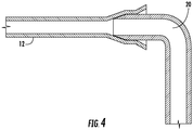
- the expansion tool 22 is withdrawn, and as shown in FIG. 4 , the return bend 20 is assembled to the tube end 18 and secured thereto by, for example, brazing.
- the bell and flare operations are performed with separate strokes of the expansion tool 22, but it is to be appreciated that, in some embodiments, the bell and flare operations may be combined into a single stroke of the expansion tool 22 if a force necessary to perform the operations does not exceed the buckling limit of the tube 12.
- Utilizing multiple strokes of the expansion tool 22 into the tube 12 to fully expand the tube 12 to a final configuration reduces the forces acting on the tube 12 due to the expansion when compared to those acting on the tube 12 in a single-stroke expansion process. Therefore, the risk of exceeding the buckling limit of the tube 12 is reduced, resulting in fewer tubes 12 which are damaged during the expansion process.
Landscapes
- Engineering & Computer Science (AREA)
- Mechanical Engineering (AREA)
- Details Of Heat-Exchange And Heat-Transfer (AREA)
- Heat-Exchange Devices With Radiators And Conduit Assemblies (AREA)
Description
- The present invention relates to a method of forming a tube for a heat exchanger according to the features of the preamble of claim 1.
- Such a method is for example disclosed in
US-A-4720902 . The subject matter disclosed herein relates to heat exchangers. More specifically, the subject disclosure relates to tubular coils for heat exchangers. - A heat exchanger typically includes two or more containment forms, such as tubes, through which a cooling fluid is circulated. The heat exchanger also includes a plurality of fins extending between the tubes which facilitate thermal energy transfer between the tubes and the surrounding air. In assembling the heat exchanger, each tube is expanded to provide an interference fit between the tube and adjacent fins. Further, ends of adjacent tubes are connected to each other via a return bend section of tubing forming a labyrinthian coil. To accommodate connection to the return bend, the end of the tube is belled (or increased in diameter) allowing the return bend to be received in the end of the tube. Further, the end of the tube is flared to capture braze material when brazing the tube to the return bend. To accomplish the expansion, bell and flare, a tool is inserted into the tube which includes a form for the expansion, or bullet, at a first end and dies to produce the bell and flare shapes at a second end. As the tool is forced down the length of the tube, the expanded shape is produced along the length, and finally the bell and flare are produced at the end of the tube. Typically this is done in a single-step process in which the tube is expanded belled and flared via a single stroke of tool along the length. This expansion method presents a problem for tubes with relatively low buckling limits, for example, tubes formed from aluminum. Aluminum tubes are typically thicker-walled than steel or cooper tubes, thus a higher force is required for the expansion process. When expansion, flare and belling forces act on a single tube simultaneously, the forces may exceed the buckling limit resulting in failure of the tube. Thus, the tube must be scrapped and replaced with another tube.
-
US 4876779 discloses a method of manufacture of a tube for a heat exchanger using an expanding/belling station with separate beller tools and expander tools. - According to the invention, a method of forming a tube for a heat exchanger includes advancing an expansion tool into a tube a first time and engaging a bullet of the expansion tool with the tube to expand the tube diametrically at least partially along a length of the tube to form an interference fit of the tube with fins of the heat exchanger. The expansion tool is at least partially retracted from the tube. The expansion tool is advanced into the tube one or more subsequent times and once the expansion of the tube by the bullet is complete, a stroke of the expansion tool is continued, thereby engaging a bell tool portion of the expansion tool with a tube end of the tube to further expand the tube end in order for the tube end to receive a return bend.
- According to a preferred aspect of the invention, a method of assembling a heat exchanger includes providing a plurality of fins and locating one or more tubes in proximity to the plurality of fins. The tubes are formed using a method as described above.
- These and other advantages and features will become more apparent from the following description of example embodiments taken in conjunction with the drawings.
- The subject matter, which is regarded as the invention, is particularly pointed out and distinctly claimed in the claims at the conclusion of the specification. The foregoing and other features, and advantages of the invention are apparent from the following detailed description taken in conjunction with the accompanying drawings in which:
-
FIG. 1 is schematic view of an embodiment of a heat exchanger; -
FIG. 2 is a cross-sectional view of an embodiment of a heat exchanger tube; -
FIG. 3 is another cross-sectional view of an embodiment of a heat exchanger tube; and -
FIG. 4 is yet another cross-sectional view of an embodiment of a heat exchanger tube. - The detailed description explains embodiments of the invention, together with advantages and features, by way of example with reference to the drawings.
- Shown in
FIG. 1 is an embodiment of aheat exchanger 10. Theheat exchanger 10 includes a plurality ofheat exchanger tubes 12, which fit to a plurality offins 14 to transfer thermal energy between aflow 16 passing through thefins 14 and the tubes. Eachtube 12 has atube end 18, which is joined to areturn bend 20 to form alabyrinth coil 22. - Referring now
FIG. 2 , anexpansion tool 22 is driven into thetube 12 to expand thetube 12 diametrically along atube length 24 to force an interference fit with thefins 14 thereby better facilitating thermal energy transfer. Further, theexpansion tool 22 is utilized to bell and flare thetube end 18 to receive thereturn bend 20. Illustrated inFIGs. 2-3 is an improved method for expanding, belling and flaring thetube end 18 for theheat exchanger 10. Referring toFIG. 2 , in an initial stroke of theexpansion tool 22 into thetube 12, thetube 12 is expanded to an interference fit with thefins 14 by abullet 26. Once the expansion of thetube 12 is complete, theexpansion tool 22 retracts along thetube 12. It is to be appreciated that while in the embodiment ofFIG. 2 , expansion of thetube 12 is achieved in a single stroke of theexpansion tool 22, it is to be appreciated that additional, multiple strokes of the expansion may be utilized to achieve the desired expansion. For example, a first stroke of theexpansion tool 22 may extend to about one half of thetube length 24, resulting in expansion of about one half of thetube 12. An additional stroke is then utilized to expand the remaining portion of thetube length 24. - Referring now to
FIG. 3 , another stroke of theexpansion tool 22 is initiated and the stroke continues until abell tool 28 portion of theexpansion tool 22 engages thetube end 18 to further expand thetube end 18 to receive thereturn bend 20. - In some embodiments, subsequent to the
bell tool portion 28 engaging thetube end 18, aflare tool portion 30 engages thetube end 18 to flare thetube end 18 outwardly. Once the bell and flare operations are completed, theexpansion tool 22 is withdrawn, and as shown inFIG. 4 , thereturn bend 20 is assembled to thetube end 18 and secured thereto by, for example, brazing. In the embodiment described above, the bell and flare operations are performed with separate strokes of theexpansion tool 22, but it is to be appreciated that, in some embodiments, the bell and flare operations may be combined into a single stroke of theexpansion tool 22 if a force necessary to perform the operations does not exceed the buckling limit of thetube 12. Utilizing multiple strokes of theexpansion tool 22 into thetube 12 to fully expand thetube 12 to a final configuration reduces the forces acting on thetube 12 due to the expansion when compared to those acting on thetube 12 in a single-stroke expansion process. Therefore, the risk of exceeding the buckling limit of thetube 12 is reduced, resulting infewer tubes 12 which are damaged during the expansion process. - While the invention has been described in detail in connection with only a limited number of embodiments, it should be readily understood that the invention is not limited to such disclosed embodiments. Rather, the invention can be modified to incorporate any number of variations, alterations, substitutions or equivalent arrangements not heretofore described, but which are commensurate with the scope of the invention as defined by the claims. Additionally, while various embodiments of the invention have been described, it is to be understood that aspects of the invention may include only some of the described embodiments. Accordingly, the invention is not to be seen as limited by the foregoing description, but is only limited by the scope of the appended claims.
Claims (7)
- A method of forming a tube for a heat exchanger (10) comprising:advancing an expansion tool (22) into a tube (12) a first time;engaging a bullet (26) of the expansion tool (22) with the tube (12) to expand the tube (12) diametrically at least partially along a length (24) of the tube (12) to form an interference fit of the tube (12) with fins (14) of the heat exchanger; andat least partially retracting the expansion tool (22) from the tube (12);characterised by:advancing the expansion tool (22) into the tube (12) one or more subsequent times; andonce the expansion of the tube by the bullet (26) is complete, continuing a stroke of the expansion tool (22) and engaging a bell tool portion (28) of the expansion tool (22) with a tube end (18) of the tube (12) to further expand the tube end in order for the tube end to receive a return bend.
- The method of Claim 1, wherein advancing the expansion tool (22) into the tube (12) the first time comprises advancing the expansion tool (22) along the entire length of the tube, thereby diametrically expanding the entire length of the tube.
- The method of Claim 1, wherein engaging the expansion tool (22) with the tube (12) one or more subsequent times results in expansion of a tube end (18) to receive a return bend (20).
- The method of Claim 1, wherein engaging the expansion tool (22) with the tube (12) one or more subsequent times results in a flare of a tube end (18).
- The method of Claim 1, wherein one or more subsequent times is one more time.
- The method of Claim 1, wherein one or more subsequent times is two more times.
- A method of assembling a heat exchanger (10) comprising:providing a plurality of fins (14);locating one or more tubes (12) in proximity to the plurality of fins; andforming the one or more tubes using a method as claimed in any preceding claim.
Applications Claiming Priority (2)
| Application Number | Priority Date | Filing Date | Title |
|---|---|---|---|
| US35635510P | 2010-06-18 | 2010-06-18 | |
| PCT/US2011/040313 WO2011159678A1 (en) | 2010-06-18 | 2011-06-14 | Heat exchanger tube and method of making |
Publications (2)
| Publication Number | Publication Date |
|---|---|
| EP2582475A1 EP2582475A1 (en) | 2013-04-24 |
| EP2582475B1 true EP2582475B1 (en) | 2021-04-28 |
Family
ID=44276110
Family Applications (1)
| Application Number | Title | Priority Date | Filing Date |
|---|---|---|---|
| EP11726635.3A Active EP2582475B1 (en) | 2010-06-18 | 2011-06-14 | Heat exchanger tube and method of making |
Country Status (4)
| Country | Link |
|---|---|
| US (1) | US20130074342A1 (en) |
| EP (1) | EP2582475B1 (en) |
| ES (1) | ES2868373T3 (en) |
| WO (1) | WO2011159678A1 (en) |
Families Citing this family (2)
| Publication number | Priority date | Publication date | Assignee | Title |
|---|---|---|---|---|
| US10882578B2 (en) * | 2018-06-13 | 2021-01-05 | Magnum Shielding Corporation | Increasing the internal pivot radii for angle-joined motorcycle handle bars |
| CN109877589A (en) * | 2018-12-14 | 2019-06-14 | 广东龙丰精密铜管有限公司 | A kind of reduced copper capillary tube pipe or pipe fitting high-efficiency high-accuracy multifunctional combination tooling |
Family Cites Families (7)
| Publication number | Priority date | Publication date | Assignee | Title |
|---|---|---|---|---|
| US2275614A (en) * | 1939-10-25 | 1942-03-10 | Babcock & Wilcox Co | Pull-type tube-expanding tool |
| US4720902A (en) * | 1986-12-22 | 1988-01-26 | Carrier Corporation | One step tension expander and method of using |
| US4876779A (en) | 1987-11-06 | 1989-10-31 | Carrier Corporation | Apparatus and method for manufacturing plate fin coils of different configurations |
| FR2710282B1 (en) * | 1993-09-25 | 1997-01-24 | Behr Gmbh & Co | Method and device for widening metal tubes of oval section by stretching. |
| JP3410883B2 (en) * | 1995-11-17 | 2003-05-26 | 京進工業株式会社 | Heat exchanger manufacturing method |
| US6163955A (en) * | 1999-09-20 | 2000-12-26 | Tsai; Ching Yuan | Tube expanding machine |
| JP4836996B2 (en) * | 2008-06-19 | 2011-12-14 | 三菱電機株式会社 | Heat exchanger and air conditioner equipped with the heat exchanger |
-
2011
- 2011-06-14 ES ES11726635T patent/ES2868373T3/en active Active
- 2011-06-14 EP EP11726635.3A patent/EP2582475B1/en active Active
- 2011-06-14 WO PCT/US2011/040313 patent/WO2011159678A1/en not_active Ceased
- 2011-06-14 US US13/641,753 patent/US20130074342A1/en not_active Abandoned
Non-Patent Citations (1)
| Title |
|---|
| None * |
Also Published As
| Publication number | Publication date |
|---|---|
| EP2582475A1 (en) | 2013-04-24 |
| US20130074342A1 (en) | 2013-03-28 |
| WO2011159678A1 (en) | 2011-12-22 |
| ES2868373T3 (en) | 2021-10-21 |
Similar Documents
| Publication | Publication Date | Title |
|---|---|---|
| EP2929269B1 (en) | Heat exchanger and method of manufacturing the same | |
| JP7243104B2 (en) | Heat exchanger and manufacturing method thereof | |
| US20180056370A1 (en) | Method of increasing thickness of tube and increased thickness tube | |
| JPH0126773B2 (en) | ||
| US9028164B2 (en) | Magnetic pulse formed vehicle driveshaft and method of making same | |
| US20160361749A1 (en) | Heat exchanger manufacturing method and diameter enlargement tool | |
| JP5094771B2 (en) | Manufacturing method of heat exchanger and air conditioner using the heat exchanger | |
| JP5561928B2 (en) | Double tube heat exchanger | |
| US20130074342A1 (en) | Heat exchanger tube and method of making | |
| JP5645852B2 (en) | Pipe joint, heat exchanger, and heat exchanger manufacturing method | |
| US20110219814A1 (en) | Tubular heat exchanger for motor vehicle air conditioners | |
| EP2596879A1 (en) | Device and method for expanding tubes | |
| JP6958238B2 (en) | How to manufacture heat exchangers and heat exchangers | |
| JP2014105951A (en) | Heat exchanger | |
| US20150219405A1 (en) | Cladded brazed alloy tube for system components | |
| WO2014098258A2 (en) | Manufacturing method for heat exchanger, device for same, and air conditioner and/or external unit thereof equipped with heat exchanger manufactured using said method | |
| JP2016032827A (en) | Manufacturing method of special shape heat transfer pipe for heat exchanger | |
| KR101932709B1 (en) | A collet sleeve block device in tube expander machine | |
| JPH0833918A (en) | Method for manufacturing metal pipe with branch pipe and header for heat exchanger using the metal pipe | |
| JP2015140981A (en) | Fin-tube heat exchanger, method for producing the same, and air conditioner | |
| JP2010078200A (en) | Heat exchanger and method of manufacturing the same | |
| JP3451492B2 (en) | Diameter reduction method for end of heat exchange tube with inner fin | |
| JPWO2018131434A1 (en) | Pipe expanding tool, pipe expanding apparatus, method of expanding heat transfer tube, and method of manufacturing heat exchanger | |
| JP2018202489A (en) | Manufacturing method of air conditioner and/or manufacturing method of outdoor unit for use in air conditioner | |
| JPH06154893A (en) | Method and device for burring copper tube |
Legal Events
| Date | Code | Title | Description |
|---|---|---|---|
| PUAI | Public reference made under article 153(3) epc to a published international application that has entered the european phase |
Free format text: ORIGINAL CODE: 0009012 |
|
| 17P | Request for examination filed |
Effective date: 20121017 |
|
| AK | Designated contracting states |
Kind code of ref document: A1 Designated state(s): AL AT BE BG CH CY CZ DE DK EE ES FI FR GB GR HR HU IE IS IT LI LT LU LV MC MK MT NL NO PL PT RO RS SE SI SK SM TR |
|
| DAX | Request for extension of the european patent (deleted) | ||
| STAA | Information on the status of an ep patent application or granted ep patent |
Free format text: STATUS: EXAMINATION IS IN PROGRESS |
|
| 17Q | First examination report despatched |
Effective date: 20171103 |
|
| GRAP | Despatch of communication of intention to grant a patent |
Free format text: ORIGINAL CODE: EPIDOSNIGR1 |
|
| STAA | Information on the status of an ep patent application or granted ep patent |
Free format text: STATUS: GRANT OF PATENT IS INTENDED |
|
| INTG | Intention to grant announced |
Effective date: 20201119 |
|
| GRAS | Grant fee paid |
Free format text: ORIGINAL CODE: EPIDOSNIGR3 |
|
| GRAA | (expected) grant |
Free format text: ORIGINAL CODE: 0009210 |
|
| STAA | Information on the status of an ep patent application or granted ep patent |
Free format text: STATUS: THE PATENT HAS BEEN GRANTED |
|
| AK | Designated contracting states |
Kind code of ref document: B1 Designated state(s): AL AT BE BG CH CY CZ DE DK EE ES FI FR GB GR HR HU IE IS IT LI LT LU LV MC MK MT NL NO PL PT RO RS SE SI SK SM TR |
|
| REG | Reference to a national code |
Ref country code: GB Ref legal event code: FG4D |
|
| REG | Reference to a national code |
Ref country code: CH Ref legal event code: EP |
|
| REG | Reference to a national code |
Ref country code: AT Ref legal event code: REF Ref document number: 1386530 Country of ref document: AT Kind code of ref document: T Effective date: 20210515 |
|
| REG | Reference to a national code |
Ref country code: DE Ref legal event code: R096 Ref document number: 602011070815 Country of ref document: DE |
|
| REG | Reference to a national code |
Ref country code: IE Ref legal event code: FG4D |
|
| REG | Reference to a national code |
Ref country code: NL Ref legal event code: FP |
|
| REG | Reference to a national code |
Ref country code: LT Ref legal event code: MG9D |
|
| REG | Reference to a national code |
Ref country code: AT Ref legal event code: MK05 Ref document number: 1386530 Country of ref document: AT Kind code of ref document: T Effective date: 20210428 |
|
| REG | Reference to a national code |
Ref country code: ES Ref legal event code: FG2A Ref document number: 2868373 Country of ref document: ES Kind code of ref document: T3 Effective date: 20211021 |
|
| PG25 | Lapsed in a contracting state [announced via postgrant information from national office to epo] |
Ref country code: LT Free format text: LAPSE BECAUSE OF FAILURE TO SUBMIT A TRANSLATION OF THE DESCRIPTION OR TO PAY THE FEE WITHIN THE PRESCRIBED TIME-LIMIT Effective date: 20210428 Ref country code: FI Free format text: LAPSE BECAUSE OF FAILURE TO SUBMIT A TRANSLATION OF THE DESCRIPTION OR TO PAY THE FEE WITHIN THE PRESCRIBED TIME-LIMIT Effective date: 20210428 Ref country code: BG Free format text: LAPSE BECAUSE OF FAILURE TO SUBMIT A TRANSLATION OF THE DESCRIPTION OR TO PAY THE FEE WITHIN THE PRESCRIBED TIME-LIMIT Effective date: 20210728 Ref country code: AT Free format text: LAPSE BECAUSE OF FAILURE TO SUBMIT A TRANSLATION OF THE DESCRIPTION OR TO PAY THE FEE WITHIN THE PRESCRIBED TIME-LIMIT Effective date: 20210428 Ref country code: HR Free format text: LAPSE BECAUSE OF FAILURE TO SUBMIT A TRANSLATION OF THE DESCRIPTION OR TO PAY THE FEE WITHIN THE PRESCRIBED TIME-LIMIT Effective date: 20210428 |
|
| PG25 | Lapsed in a contracting state [announced via postgrant information from national office to epo] |
Ref country code: RS Free format text: LAPSE BECAUSE OF FAILURE TO SUBMIT A TRANSLATION OF THE DESCRIPTION OR TO PAY THE FEE WITHIN THE PRESCRIBED TIME-LIMIT Effective date: 20210428 Ref country code: SE Free format text: LAPSE BECAUSE OF FAILURE TO SUBMIT A TRANSLATION OF THE DESCRIPTION OR TO PAY THE FEE WITHIN THE PRESCRIBED TIME-LIMIT Effective date: 20210428 Ref country code: LV Free format text: LAPSE BECAUSE OF FAILURE TO SUBMIT A TRANSLATION OF THE DESCRIPTION OR TO PAY THE FEE WITHIN THE PRESCRIBED TIME-LIMIT Effective date: 20210428 Ref country code: GR Free format text: LAPSE BECAUSE OF FAILURE TO SUBMIT A TRANSLATION OF THE DESCRIPTION OR TO PAY THE FEE WITHIN THE PRESCRIBED TIME-LIMIT Effective date: 20210729 Ref country code: IS Free format text: LAPSE BECAUSE OF FAILURE TO SUBMIT A TRANSLATION OF THE DESCRIPTION OR TO PAY THE FEE WITHIN THE PRESCRIBED TIME-LIMIT Effective date: 20210828 Ref country code: PT Free format text: LAPSE BECAUSE OF FAILURE TO SUBMIT A TRANSLATION OF THE DESCRIPTION OR TO PAY THE FEE WITHIN THE PRESCRIBED TIME-LIMIT Effective date: 20210830 Ref country code: PL Free format text: LAPSE BECAUSE OF FAILURE TO SUBMIT A TRANSLATION OF THE DESCRIPTION OR TO PAY THE FEE WITHIN THE PRESCRIBED TIME-LIMIT Effective date: 20210428 Ref country code: NO Free format text: LAPSE BECAUSE OF FAILURE TO SUBMIT A TRANSLATION OF THE DESCRIPTION OR TO PAY THE FEE WITHIN THE PRESCRIBED TIME-LIMIT Effective date: 20210728 |
|
| PG25 | Lapsed in a contracting state [announced via postgrant information from national office to epo] |
Ref country code: SM Free format text: LAPSE BECAUSE OF FAILURE TO SUBMIT A TRANSLATION OF THE DESCRIPTION OR TO PAY THE FEE WITHIN THE PRESCRIBED TIME-LIMIT Effective date: 20210428 Ref country code: SK Free format text: LAPSE BECAUSE OF FAILURE TO SUBMIT A TRANSLATION OF THE DESCRIPTION OR TO PAY THE FEE WITHIN THE PRESCRIBED TIME-LIMIT Effective date: 20210428 Ref country code: DK Free format text: LAPSE BECAUSE OF FAILURE TO SUBMIT A TRANSLATION OF THE DESCRIPTION OR TO PAY THE FEE WITHIN THE PRESCRIBED TIME-LIMIT Effective date: 20210428 Ref country code: CZ Free format text: LAPSE BECAUSE OF FAILURE TO SUBMIT A TRANSLATION OF THE DESCRIPTION OR TO PAY THE FEE WITHIN THE PRESCRIBED TIME-LIMIT Effective date: 20210428 Ref country code: EE Free format text: LAPSE BECAUSE OF FAILURE TO SUBMIT A TRANSLATION OF THE DESCRIPTION OR TO PAY THE FEE WITHIN THE PRESCRIBED TIME-LIMIT Effective date: 20210428 Ref country code: RO Free format text: LAPSE BECAUSE OF FAILURE TO SUBMIT A TRANSLATION OF THE DESCRIPTION OR TO PAY THE FEE WITHIN THE PRESCRIBED TIME-LIMIT Effective date: 20210428 Ref country code: MC Free format text: LAPSE BECAUSE OF FAILURE TO SUBMIT A TRANSLATION OF THE DESCRIPTION OR TO PAY THE FEE WITHIN THE PRESCRIBED TIME-LIMIT Effective date: 20210428 |
|
| REG | Reference to a national code |
Ref country code: DE Ref legal event code: R097 Ref document number: 602011070815 Country of ref document: DE Ref country code: CH Ref legal event code: PL |
|
| PLBE | No opposition filed within time limit |
Free format text: ORIGINAL CODE: 0009261 |
|
| STAA | Information on the status of an ep patent application or granted ep patent |
Free format text: STATUS: NO OPPOSITION FILED WITHIN TIME LIMIT |
|
| GBPC | Gb: european patent ceased through non-payment of renewal fee |
Effective date: 20210728 |
|
| PG25 | Lapsed in a contracting state [announced via postgrant information from national office to epo] |
Ref country code: LU Free format text: LAPSE BECAUSE OF NON-PAYMENT OF DUE FEES Effective date: 20210614 |
|
| 26N | No opposition filed |
Effective date: 20220131 |
|
| PG25 | Lapsed in a contracting state [announced via postgrant information from national office to epo] |
Ref country code: LI Free format text: LAPSE BECAUSE OF NON-PAYMENT OF DUE FEES Effective date: 20210630 Ref country code: IE Free format text: LAPSE BECAUSE OF NON-PAYMENT OF DUE FEES Effective date: 20210614 Ref country code: GB Free format text: LAPSE BECAUSE OF NON-PAYMENT OF DUE FEES Effective date: 20210728 Ref country code: CH Free format text: LAPSE BECAUSE OF NON-PAYMENT OF DUE FEES Effective date: 20210630 |
|
| PG25 | Lapsed in a contracting state [announced via postgrant information from national office to epo] |
Ref country code: IS Free format text: LAPSE BECAUSE OF FAILURE TO SUBMIT A TRANSLATION OF THE DESCRIPTION OR TO PAY THE FEE WITHIN THE PRESCRIBED TIME-LIMIT Effective date: 20210828 Ref country code: AL Free format text: LAPSE BECAUSE OF FAILURE TO SUBMIT A TRANSLATION OF THE DESCRIPTION OR TO PAY THE FEE WITHIN THE PRESCRIBED TIME-LIMIT Effective date: 20210428 |
|
| PGFP | Annual fee paid to national office [announced via postgrant information from national office to epo] |
Ref country code: NL Payment date: 20220523 Year of fee payment: 12 |
|
| PGFP | Annual fee paid to national office [announced via postgrant information from national office to epo] |
Ref country code: BE Payment date: 20220523 Year of fee payment: 12 |
|
| PG25 | Lapsed in a contracting state [announced via postgrant information from national office to epo] |
Ref country code: HU Free format text: LAPSE BECAUSE OF FAILURE TO SUBMIT A TRANSLATION OF THE DESCRIPTION OR TO PAY THE FEE WITHIN THE PRESCRIBED TIME-LIMIT; INVALID AB INITIO Effective date: 20110614 Ref country code: CY Free format text: LAPSE BECAUSE OF FAILURE TO SUBMIT A TRANSLATION OF THE DESCRIPTION OR TO PAY THE FEE WITHIN THE PRESCRIBED TIME-LIMIT Effective date: 20210428 |
|
| REG | Reference to a national code |
Ref country code: NL Ref legal event code: MM Effective date: 20230701 |
|
| REG | Reference to a national code |
Ref country code: BE Ref legal event code: MM Effective date: 20230630 |
|
| PG25 | Lapsed in a contracting state [announced via postgrant information from national office to epo] |
Ref country code: NL Free format text: LAPSE BECAUSE OF NON-PAYMENT OF DUE FEES Effective date: 20230701 |
|
| PG25 | Lapsed in a contracting state [announced via postgrant information from national office to epo] |
Ref country code: MK Free format text: LAPSE BECAUSE OF FAILURE TO SUBMIT A TRANSLATION OF THE DESCRIPTION OR TO PAY THE FEE WITHIN THE PRESCRIBED TIME-LIMIT Effective date: 20210428 |
|
| PG25 | Lapsed in a contracting state [announced via postgrant information from national office to epo] |
Ref country code: BE Free format text: LAPSE BECAUSE OF NON-PAYMENT OF DUE FEES Effective date: 20230630 |
|
| PG25 | Lapsed in a contracting state [announced via postgrant information from national office to epo] |
Ref country code: MT Free format text: LAPSE BECAUSE OF FAILURE TO SUBMIT A TRANSLATION OF THE DESCRIPTION OR TO PAY THE FEE WITHIN THE PRESCRIBED TIME-LIMIT Effective date: 20210428 |
|
| PGFP | Annual fee paid to national office [announced via postgrant information from national office to epo] |
Ref country code: ES Payment date: 20240701 Year of fee payment: 14 |
|
| PGFP | Annual fee paid to national office [announced via postgrant information from national office to epo] |
Ref country code: DE Payment date: 20250520 Year of fee payment: 15 |
|
| PGFP | Annual fee paid to national office [announced via postgrant information from national office to epo] |
Ref country code: IT Payment date: 20250520 Year of fee payment: 15 |
|
| PGFP | Annual fee paid to national office [announced via postgrant information from national office to epo] |
Ref country code: FR Payment date: 20250520 Year of fee payment: 15 |
|
| PG25 | Lapsed in a contracting state [announced via postgrant information from national office to epo] |
Ref country code: TR Free format text: LAPSE BECAUSE OF FAILURE TO SUBMIT A TRANSLATION OF THE DESCRIPTION OR TO PAY THE FEE WITHIN THE PRESCRIBED TIME-LIMIT Effective date: 20210428 |