EP2581645B1 - Modularer Strahler - Google Patents
Modularer Strahler Download PDFInfo
- Publication number
- EP2581645B1 EP2581645B1 EP12188508.1A EP12188508A EP2581645B1 EP 2581645 B1 EP2581645 B1 EP 2581645B1 EP 12188508 A EP12188508 A EP 12188508A EP 2581645 B1 EP2581645 B1 EP 2581645B1
- Authority
- EP
- European Patent Office
- Prior art keywords
- module
- fastening
- recessed
- mounting
- parts
- Prior art date
- Legal status (The legal status is an assumption and is not a legal conclusion. Google has not performed a legal analysis and makes no representation as to the accuracy of the status listed.)
- Not-in-force
Links
- 238000003780 insertion Methods 0.000 claims description 2
- 230000037431 insertion Effects 0.000 claims description 2
- 238000013022 venting Methods 0.000 claims 1
- 238000009423 ventilation Methods 0.000 description 9
- 238000000034 method Methods 0.000 description 5
- 238000001816 cooling Methods 0.000 description 2
- 239000000463 material Substances 0.000 description 2
- 239000003086 colorant Substances 0.000 description 1
- 238000010276 construction Methods 0.000 description 1
- 230000000694 effects Effects 0.000 description 1
- 230000005611 electricity Effects 0.000 description 1
- 238000005265 energy consumption Methods 0.000 description 1
- 229920002457 flexible plastic Polymers 0.000 description 1
- 229910052736 halogen Inorganic materials 0.000 description 1
- 150000002367 halogens Chemical class 0.000 description 1
- 238000010438 heat treatment Methods 0.000 description 1
- 238000009434 installation Methods 0.000 description 1
- 238000009413 insulation Methods 0.000 description 1
- 230000007774 longterm Effects 0.000 description 1
- 238000004519 manufacturing process Methods 0.000 description 1
- 238000012856 packing Methods 0.000 description 1
- 239000011120 plywood Substances 0.000 description 1
- 238000012360 testing method Methods 0.000 description 1
- 239000002918 waste heat Substances 0.000 description 1
Images


Classifications
-
- F—MECHANICAL ENGINEERING; LIGHTING; HEATING; WEAPONS; BLASTING
- F21—LIGHTING
- F21S—NON-PORTABLE LIGHTING DEVICES; SYSTEMS THEREOF; VEHICLE LIGHTING DEVICES SPECIALLY ADAPTED FOR VEHICLE EXTERIORS
- F21S8/00—Lighting devices intended for fixed installation
- F21S8/02—Lighting devices intended for fixed installation of recess-mounted type, e.g. downlighters
-
- F—MECHANICAL ENGINEERING; LIGHTING; HEATING; WEAPONS; BLASTING
- F21—LIGHTING
- F21V—FUNCTIONAL FEATURES OR DETAILS OF LIGHTING DEVICES OR SYSTEMS THEREOF; STRUCTURAL COMBINATIONS OF LIGHTING DEVICES WITH OTHER ARTICLES, NOT OTHERWISE PROVIDED FOR
- F21V17/00—Fastening of component parts of lighting devices, e.g. shades, globes, refractors, reflectors, filters, screens, grids or protective cages
- F21V17/10—Fastening of component parts of lighting devices, e.g. shades, globes, refractors, reflectors, filters, screens, grids or protective cages characterised by specific fastening means or way of fastening
-
- F—MECHANICAL ENGINEERING; LIGHTING; HEATING; WEAPONS; BLASTING
- F21—LIGHTING
- F21V—FUNCTIONAL FEATURES OR DETAILS OF LIGHTING DEVICES OR SYSTEMS THEREOF; STRUCTURAL COMBINATIONS OF LIGHTING DEVICES WITH OTHER ARTICLES, NOT OTHERWISE PROVIDED FOR
- F21V21/00—Supporting, suspending, or attaching arrangements for lighting devices; Hand grips
- F21V21/02—Wall, ceiling, or floor bases; Fixing pendants or arms to the bases
- F21V21/04—Recessed bases
Definitions
- the present invention concerns a number of components or parts forming part of a modular recessed spot system.
- a recessed spot also called an insert, consists of a cylindrical box with an end piece and mounting devices arranged for fastening the recessed spot.
- an ornamental ring for covering the recessed spot in relation to the surrounding ceiling or covering.
- WO 2009/080046 Al disclose a mounting device for recessed spots comprising an expansion module with a circular skirt with slots distributed on the periphery and with fastening means, and a fastening module and a cover module.
- EP2180240 disclose a lamp aperture holder comprising a substantially tubular main body having a flexible section. A flange is provided integral with said body for supporting said holder when fitted in a lamp aperture. The body being biased towards the lamp aperture by the flexible nature of the body.
- US 5,031,084 disclose an adjustable mounting frame for mounting recessed lighting fixtures.
- the mounting frame includes a mounting ring and spring members which can hold a lighting fixture trim, i.e. housing in place.
- recessed spots for many different purposes entails that a large number of recessed spots are to be kept in stock so that a recessed spot with the desired properties can be delivered quickly, and that the installer has to be informed of the frequently very different methods and means for installing the many different types of spotlights.
- this furthermore requires many different routines with regard to adjustment of the machines for making the individual components and just as much in connection with mounting where the different recessed spots often require different and varying mounting procedures that may entail errors and lower quality.
- a fastening module in the following also called a locking ring, which can be adapted to different types of recessed spots and/or recessed boxes.
- the locking ring is characterised in that the locking ring can be used as fastening module for recessed lighting spots or recessed boxes for lighting spots, wherein the locking ring includes an annular main part, and wherein in the main part an expansion element is provided such that the circumference of the annular part can be adjusted so that the diameter can be reduced or increased, wherein the annular main part includes an inner side and an outer side, and wherein the outer side is provided with a groove.
- the locking ring is usable for mounting very different elements in a plate-shaped item.
- the kit comprises multiple different parts, such as a plurality of fastening modules, plurality of expansion modules etc. In this manner it is possible to select suitable parts from the plurality of parts of each type in order to, from standard parts, assemble a recessed spot having special requirements.
- the locking ring is further characterised in that the locking ring constitutes a plane and that in the locking ring two or more linearly displaceable fastening members are arranged at right angles to the plane of the locking ring, the members capable of being pivoted about the linearly displaceable part, and wherein each member has a part which can be brought to project beyond the outer diameter of the ring.
- the locking ring constitutes a plane and that in the locking ring two or more linearly displaceable fastening members are arranged at right angles to the plane of the locking ring, the members capable of being pivoted about the linearly displaceable part, and wherein each member has a part which can be brought to project beyond the outer diameter of the ring.
- the recessed box is arranged in a hole in a building element by means of the locking ring where the hole has a minimum size and the fastening members can be pivoted beyond the plane of the locking ring (and the plane of the mounting box as well), and where the linear movement of the fastening members can be controlled from within the recessed box or the locking ring, a very secure mounting is thus ensured as opposed to the well-know spring devices that imply a substantial uncertainty in connection with what they bear against (wires, insulation, or other) as well as the securing force can be unambiguously determined by the linearly displaceable members.
- the invention provides for this purpose by a modular kit of parts for a recessed spot, the kit comprising:
- the standardised method in particular by mounting the individual components and parts in the recessed spot, furthermore enables use of robots entirely or partially in connection with assembling the individual recessed spots.
- system additionally includes
- a recessed spot will typically have a largely symmetric centre axis corresponding with the direction in which the light is emitted from the spotlight.
- the rear pieces may vary in length in longitudinal direction of the axis such that the rear pieces can be shaped as lids, i.e. their extension along the longitudinal axis is very limited, or they may have different determined modular dimensions such that the length of the rear piece along the longitudinal axis can be 30, 60, 110, 50 mm, etc.
- the mounting module is designed such that the wire passage is disposed at the same location relative to the means for fastening the electric components which in a mounting situation will make it relatively simple to mount the desired components.
- the modular kit of parts is further extended so that the kit of parts further includes an arm which is provided with one or more hinged segments or another form of flexible and bendable members, wherein the mounting module an inner side and an outer side, wherein at the outer side there is provided means for releasable fastening of the arm or another form of flexible member, and wherein the arm or the flexible member projects largely at right angles from the outer side.
- the hinged arm enables more space-consuming elements, such as e.g. transformers, terminals, wire reliefs, various electronics etc., to be mounted on the arm, and that the hinged or secured flexible members enable that these components can be inserted in the mounting hole before the recessed spot itself so that the opening to be provided in the recessed part in order to secure the spotlight does not have to be larger than the circumference of the spot itself.
- space-consuming elements such as e.g. transformers, terminals, wire reliefs, various electronics etc.
- the mounting module with fastening means for the hinged arm or the flexible member as in the case the electric components described above it may be preassembled, and in addition the mounting procedure is well-known as the hinged arm/member and the means for fastening the hinged arm or the flexible member at the outer side of the mounting module are well-known and standard for every one of the recessed spots that can be composed by the kit of parts in the recessed spot system.
- the modular kit of parts contain a mounting module in which is provided a flexible wire lead-in, preferably designed as a cutout in the wall of the mounting module or at the top of the module with subsequent insertion of a flexible wire lead-in.
- a flexible wire lead-in preferably designed as a cutout in the wall of the mounting module or at the top of the module with subsequent insertion of a flexible wire lead-in.
- a ventilator in the mounting module and/or in connection with the rear piece.
- the ventilator is provided such that it can produce an airflow past the light source and thereby cool the light source.
- light sources of the LED type it is important to keep the temperature within a certain interval since the LED light source has optimal light emission in relation to the energy consumption at the correct operating temperature and in addition the light source has a considerably longer service life.
- a ventilator not so much for keeping the light source temperate but so as to utilise the waste heat produced by the light source, e.g. for heating the room in which the recessed spot is located.
- the ventilator can create an airflow, both from outside and in and from inside and out, depending on the desired effect.
- the ventilator may advantageously be set to suck such that the air inside the room is sucked past the light source, thereby cooling the exhausted air which is then discharged at the back side of the building element.
- the ventilator may advantageously be mounted with varying distance from the light source such that the ventilator can either be mounted directly in the mounting module or can be arranged via an intermediate piece at a given distance from the mounting module in the same way as the rear pieces.
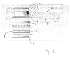
- Figs. 1 and 2 are illustrated the various parts which together constitute a modular kit of parts for a recessed spot.
- a recessed spot which after assembling will have a height of 60 mm
- a recessed spot which after assembling will have a height of 110 mm.
- the recessed spot is shown in so-called exploded view where the individual components clearly appear.
- Both of the recessed spots consist of a rear piece 1, a mounting module 2, an expansion module 3, a fastening module 4 and a cover 5, respectively.
- the recessed spot is furthermore provided with an arm 6 which by means of a double hinge 7, 8 is releasably fastened to the mounting module 2 in an envelope-shaped holder 9.
- a wire holder 10 is indicated in the mounting module.
- the wire holder 10 is usually designed in a rubber-like material such that the outer dimensions are uniform whereas the aperture provided in the wire holder varies according to the type of wire used for leading electricity to the light source mounted in the recessed spot.
- a box 11 is provided on the hinged arm 6, in which box 11 there may be located a transformer, a wire holder/relief, connecting terminal which is shown with reference to Fig. 4 , or other equipment for the recessed spot.
- Fig. 2 is shown an insert for a recessed spot with a height of 110 mm.
- the feature causing the changed built-in height is the extension of the rear piece 1 in the longitudinal axis 20 of the recessed spot.
- all other parts i.e. the mounting module 2, the expansion module 3, the fastening module 4 and the cover 5 are identical to the corresponding modules depicted in Fig. 1 . In that way it is thus possible with standard components to provide a large number of recessed spots with varying dimensions from the kit of parts which is part of the invention.
- the cover 5 may of course be made with different designs, colours, materials etc. such that the part of the recessed spot becoming visible after mounting fits into the environment into which the recessed spot is built.
- the insert consisting of the parts described above are mounted in an opening in a building element by inserting the insert from below, and when the flaps 3' of the expansion module are outside the building element, e.g. a ceiling sheet, a plywood sheet or similar, the fastening module 4 is actuated such that the diameter of the fastening module is made larger whereby the flaps 3' are bent outwards relative to the longitudinal axis 20, engaging the surrounding opening in the building element.
- the insert is hereby fastened in relation the building element.
- the cover 5 is mounted in that the bayonet socket 12 provided in the mounting end of the cover 5 is pushed in and turned relative to pins 13 in the fastening module.
- FIG. 3 A cross-section through an insert according to the invention is indicated with reference to Fig. 3 .
- the insert includes a rear piece 1 which is clicked into the mounting module 2.
- an O-ring 15 can be inserted, in particular in the joints between the rear piece and the mounting module and the expansion module, respectively, such that tightness is achieved. Tightness is important as modem buildings are to be made such as to pass a tightness test, i.e. leaks causing loss of heat and the like must not exist, and by making the recessed spot in this way with a largely airtight housing it is ensured that it is not the recessed spot as such that gives rise to leaks, thereby causing the construction not to fulfil the requirements for tightness. Furthermore, an O-ring in the click joint between the above mentions modules will act as a resilient clamping such that the individual parts are secured in a better way.
- the mounting module 2 is also clicked to the expansion module 3.
- the fastening module has an outer diameter such that as illustrated in Fig. 3 it can be disposed internally of a lower part of the expansion module opposite the flaps of the expansion module.
- the flaps will be pressed outwards and go against the surrounding building element, thereby fixing the recessed spot in relation to the building element.
- the surface 15 of the building element is marked as being flush with the back side of the cover 5 such that a tightly fitting mounting of the recessed spot relative to the building element 15 is achieved.
- the arm 6 is designed with a curving part 16 such that the arm can be displaced at the back side of the building element 15 during and after mounting and due to the rounding slide across possible irregularities, such as joints between elements of which the building element 15 may be made up of, wires lying loosely on the ceiling sheet or other obstacles that may prevent the arm 6 from coming into contact with the back side of the building element 15.
- the arm 6 bears on the back side of the building element 15, the recessed spot is relieved due to the two pivotable hinges 7, 8, and thereby the fastening itself against the building element by means of the fastening module is relieved and not subjected to eccentric load so that a long-term and durable fastening is achieved without unfavourable eccentric load.
- the fastening module includes an expansion element which by turning the screw 17 causes the diameter to be reduced or increased, respectively.
- the screw 17 can be actuated from the interior of the recessed spot such that fastening of the recessed spot can be effected expediently via the interior of the recessed spot after being passed up through a hole in the building element 15.
- Fig. 4 is illustrated a cross-section through yet an embodiment of the invention where a wire relief/terminal 38 is provided on the arm 6, covered by the box 11.
- a lead-in 11' such that the live wire for supplying the recessed spot with energy can be mounted in the terminal 38.
- the recessed spot can be preassembled, i.e. light source with electric connection to the terminal possibly with LED driver or transformer can be preassembled industrially such that the electric wire conducting current to the light source is only to be connected in the terminal in connection with onsite installation of the recessed spot.
- a V-shaped groove 18 in the fastening module 4 which groove 18 is used for receiving pins 21, see Fig. 5 .
- the pins are used for mechanically fixing the fastening module in relation to the expansion module whereby the light source (not shown) can be turned in relation to the position of the recessed box in the building element in order to attain a possible desired direction of the light emission.
- a packing 19 which corresponding to the above mentioned O-rings is to provide the wanted tightness between the rear edge of the recessed box, i.e. the edge 4" abutting on the cover 5, whereby tightness is achieved here as well.
- Fig. 5 is finally shown a relatively low recessed spot corresponding to the recessed spot in Fig. 1 wherein, as already mentioned above, fixing pins 21 have been provided for fixing the fastening module 4 relative to the expansion module 3.
- a ventilation module 25 including a ventilator 26 is provided.
- the ventilation module 25 is mounted in the same way as the rear piece 1, i.e. by being attached on the mounting module by clicking.
- the ventilation module 25 consists of a rear piece 27 that fits tightly against the mounting module such that a largely airtight joint is achieved between the rear piece 27 and the mounting module 2.
- the ventilator 26 is supplied with energy via the wire connected to the terminal 38, see Fig. 4 .
- the ventilation module 25 can be designed with a plug so that when the ventilation module 25 is inserted in the mounting module 2, the plug can be inserted into a corresponding socket provided in a component mounted in the box 11 on the arm 6 in a corresponding way.
- the mounting of the ventilation module 25 is hereby facilitated and expedited.
- the arm 6 is shown mounted on the mounting module 2 by means of the envelope holder 9.
- the ventilation module 25 is shown mounted partly on the holder 9 for the arm 6 and partly on a further holder 9'.
- the holders 9, 9' are here mounted at an upper part of the expansion module 3 by means of screw connections 31.
- blanking off pieces are placed instead of the holders 9, 9'.
- the ventilator module 25 can be arranged at varying levels as the releasable fastening of the ventilator module is squeezed around the arm 29 (part of the holder 9'). Hereby, ventilation for different types and sizes of light sources can be allowed for.
- the ventilator module can either be designed as closed, i.e. when mounted on the mounting module 2 a largely airtight assembly is created as described above, or the module may have one or more ventilation slots so that cooling air can be exhausted above the ceiling or air from above the ceiling can be passed down past the light source.
- the fastening module/locking ring 4 is illustrated in Fig. 7 .
- the locking ring forms an X-Z plane.
- two linearly displaceable fastening members 30, 31 are arranged.
- each member is designed as a bolt with a head 32, 33 and a shank 34, 35 provided with a screw thread.
- holes with corresponding screw threads are provided such that by turning the head 32, 33 the fastening members 30, 31 can be moved linearly closer to or farther from the plane X-Z of the locking ring.
- projecting parts 36, 37 On the fastening members 30, 31 there is furthermore provided projecting parts 36, 37.
- These parts 36, 37 can be pivoted about the linear fastening legs such that the part can be brought outside the outer periphery of the locking ring.
- the parts 36, 37 then are displaced linearly up/down relative to the X-Z plane, the parts 36, 37 can be brought into contact with the building or furniture element in which the locking ring is to be mounted.
Landscapes
- Engineering & Computer Science (AREA)
- General Engineering & Computer Science (AREA)
- Arrangement Of Elements, Cooling, Sealing, Or The Like Of Lighting Devices (AREA)
Claims (8)
- Baukastensystem aus Teilen für Einbaustrahler, mit:a) einer Mehrzahl an Erweiterungsmodulen (3), wobei jedes Modul (3) einen zylinderförmigen Hülsenteil mit einer Unterkante aufweist, wobei an der Unterkante eine Anzahl an Nuten in longitudinaler Richtung des Zylinders vorgesehen sind, welche auf dem Umfang angeordnet sind und wobei an der der Unterkante gegenüberliegenden Kante Befestigungsmittel vorgesehen sind;b) einem Befestigungsmodul (4) mit einem äußeren Umfang und einem inneren Umfang, wobei der äußere Umfang im Wesentlichen einem inneren Umfang des zylinderförmigen Hülsenteils des Erweiterungsmoduls (3) entspricht und wobei das Befestigungsmodul (4) Mittel zur stufenlosen Erweiterung zumindest des äußeren Umfangs und Befestigungsmittel an dem inneren Umfang aufweist zum Befestigenc) eines oder mehrerer Deckelmodule (5), wobei Mittel zum Montieren einer Lichtquelle oder eines gesamten Downlights in dem Deckelmodul (5) vorgesehen sind;wobei das Befestigungsmodul (4) im Inneren des Erweiterungsmoduls (3) gegenüber den Nuten anbringbar ist.
- Baukastensystem aus Teilen für einen Einbaustrahler nach Anspruch 1, wobei das Baukastensystem ferner aufweist:d) eine Mehrzahl an hinteren Teilen (1), wobei die hinteren Teile befestigt sind ine) einem Montagemodul (2) zum Befestigen und Sichern elektrischer Komponenten (11);wobei jedes der hinteren Teile (1) mit dem Montagemodul (2) in Rasteingriff bringbar ist und jedes der Erweiterungsmodule (3) mit dem Montagemodul (2) in Rasteingriff bringbar ist.
- Baukastensystem aus Teilen für einen Einbaustrahler nach Anspruch 1 oder 2, dadurch gekennzeichnet, dass das Baukastensystem ferner einen Arm (6) aufweist, wobei an dem Arm (6) ein oder mehrere Drehgelenke (7, 8) vorgesehen sind, wobei das Erweiterungsmodul (3) in dem oberen Teil Mittel (9) zum lösbaren Befestigen des Arms (6) aufweist oder wobei das Montagemodul (2) eine Innenseite und eine Außenseite aufweist, wobei an der Außenseite Mittel (9) zum lösbaren Befestigen des Arms (6) vorgesehen sind und wobei der Arm (6) im Wesentlichen in einem rechten Winkel von der Außenseite des Einbaustrahlers vorsteht.
- Baukastensystem aus Teilen für einen Einbaustrahler nach Anspruch 1, dadurch gekennzeichnet, dass das Montagemodul (2) einen flexiblen Zuleitungsdraht (11) aufweist, welcher vorzugsweise als Ausschnitt in der Wand des Montagemoduls (2) mit anschließender Einbringung eines flexiblen Zuleitungsdrahtes (11') ausgebildet ist.
- Baukastensystem aus Teilen für einen Einbaustrahler nach Anspruch 1 oder 2, dadurch gekennzeichnet, dass Mittel in dem Erweiterungsmodul (3) oder Montagemodul (2) zum verstellbaren Anbringen eines Ventilatormoduls (25) vorgesehen sind, welche eine hintere Aufnahme (27) und einen Ventilator (26) aufweisen, wobei die hintere Aufnahme (27) Mittel (38) für die elektrische Verbindung mit dem Ventilator (26) und mit einer Energiequelle aufweist.
- Baukastensystem aus Teilen für einen Einbaustrahler nach Anspruch 5, dadurch gekennzeichnet, dass das Ventilatormodul (25) zwischen dem Ventilator (26) und der hinteren Aufnahme (27) eine Lüftungsöffnung bildet, durch welche Luft jeweils in den Einbaustrahler einsaugbar und aus dem Einbaustrahler herausblasbar ist.
- Baukastensystem aus Teilen für einen Einbaustrahler nach Anspruch 3, dadurch gekennzeichnet, dass ein oder mehrere elektrische Komponenten (11) an dem Arm (6) vorgesehen sind, wobei die elektrischen Komponenten (11) einen Transformator, einen elektrischen Anschluss, eine elektrische Steuerung einer Lichtquelle, einen Treiber für eine LED-Lichtquelle oder andere relevante Bauteile aufweisen können.
- Verriegelungsring, welcher als Befestigungsmodul (4) für Einbaustrahler oder Einbauaufnahmen für Einbauleuchten verwendbar ist, wobei der Verriegelungsring (4) einen ringförmigen Grundkörper aufweist, dadurch gekennzeichnet, dass in dem Grundkörper ein Erweiterungselement derart vorgesehen ist, dass der Umfang des ringförmigen Grundkörpers derart anpassbar ist, dass der Umfang reduziert oder erhöht werden kann, wobei der ringförmige Grundkörper eine Innenseite und eine Außenseite aufweist und wobei an der Außenseite eine Nut (18) vorgesehen ist und wobei der Verriegelungsring (4) eine Ebene bildet, und dass in dem Verriegelungsring (4) zwei oder mehr linear verstellbare Befestigungsglieder (30, 31) in rechten Winkeln zu der Ebene des Verriegelungsrings angeordnet sind, wobei die Glieder (30, 31) dazu geeignet sind, um den linear versstellbaren Teil (30, 31) gedreht zu werden, und wobei jedes Glied einen Teil (37) aufweist, welcher über den äußeren Umfang des Verriegelungsrings (4) hinaustreten kann.
Applications Claiming Priority (1)
| Application Number | Priority Date | Filing Date | Title |
|---|---|---|---|
| DKPA201170569 | 2011-10-13 |
Publications (2)
| Publication Number | Publication Date |
|---|---|
| EP2581645A1 EP2581645A1 (de) | 2013-04-17 |
| EP2581645B1 true EP2581645B1 (de) | 2014-08-27 |
Family
ID=47008420
Family Applications (1)
| Application Number | Title | Priority Date | Filing Date |
|---|---|---|---|
| EP12188508.1A Not-in-force EP2581645B1 (de) | 2011-10-13 | 2012-10-15 | Modularer Strahler |
Country Status (1)
| Country | Link |
|---|---|
| EP (1) | EP2581645B1 (de) |
Families Citing this family (4)
| Publication number | Priority date | Publication date | Assignee | Title |
|---|---|---|---|---|
| CN110360496A (zh) * | 2018-03-26 | 2019-10-22 | 罗维和 | 路桥led投射灯抗震固定架 |
| CN111878740B (zh) * | 2020-08-22 | 2021-07-06 | 深圳市元本室内建筑设计有限公司 | 一种室内用节能灯 |
| EP4075056B1 (de) * | 2021-04-12 | 2025-06-25 | Daxtor A/S | Befestigungsvorrichtung |
| CN115183176B (zh) * | 2022-07-07 | 2023-12-08 | 国网安徽省电力有限公司亳州供电公司 | 一种易于拆装维护的led工矿灯 |
Family Cites Families (3)
| Publication number | Priority date | Publication date | Assignee | Title |
|---|---|---|---|---|
| US5031084A (en) * | 1990-01-03 | 1991-07-09 | Lightolier, Inc. | Universal remodeler frame-in kit |
| US20100294560A1 (en) * | 2007-12-21 | 2010-11-25 | Torben Dahl | Mounting device for mounting electric components |
| GB2464697A (en) * | 2008-10-22 | 2010-04-28 | Ilker Hakki | A lamp aperture collar |
-
2012
- 2012-10-15 EP EP12188508.1A patent/EP2581645B1/de not_active Not-in-force
Also Published As
| Publication number | Publication date |
|---|---|
| EP2581645A1 (de) | 2013-04-17 |
Similar Documents
| Publication | Publication Date | Title |
|---|---|---|
| US11493187B2 (en) | Recessed light-emitting diode lighting fixture | |
| US10683994B2 (en) | Multi-piece frames | |
| CA2945763C (en) | Adjustable dual optic directional lamp assembly | |
| US12313239B2 (en) | Recessed downlight fixture | |
| US9383090B2 (en) | Floodlights with multi-path cooling | |
| US9857038B2 (en) | Recessed downlight fixture and method for installing and universally adjusting the fixture in a new construction application | |
| US8287142B2 (en) | Conversion kit for lighting assemblies | |
| US10378734B2 (en) | Wall wash light fixture | |
| EP2581645B1 (de) | Modularer Strahler | |
| US20200263838A1 (en) | Light Bulb Shaped Light Emitting Diode Module | |
| US20100294560A1 (en) | Mounting device for mounting electric components | |
| US20080285291A1 (en) | Recessed light retrofit kit | |
| KR20170041492A (ko) | 엘이디 광원판과 컨트롤러가 분리 조립되게 한 조명등 | |
| US7622701B2 (en) | Toolessly adjustable cupola and photocontrol receptacle assembly | |
| KR101879996B1 (ko) | 조명등의 투광판 장착장치 | |
| US20190285261A1 (en) | Light fixture | |
| US20200116334A1 (en) | Replaceable Baffles For Light Fixtures | |
| EP2157370B1 (de) | Anpassbarer Einsatz | |
| KR200362104Y1 (ko) | 조명등 장착구조 | |
| CA3051396A1 (en) | Universal mounting assembly | |
| CA3010273C (en) | Light fixture | |
| JP2007227182A (ja) | 照明器具 | |
| JP2006230113A (ja) | ライティングダクト装置 | |
| KR200326751Y1 (ko) | 조명등용 브래킷 | |
| JP2017016743A (ja) | 照明器具 |
Legal Events
| Date | Code | Title | Description |
|---|---|---|---|
| PUAI | Public reference made under article 153(3) epc to a published international application that has entered the european phase |
Free format text: ORIGINAL CODE: 0009012 |
|
| AK | Designated contracting states |
Kind code of ref document: A1 Designated state(s): AL AT BE BG CH CY CZ DE DK EE ES FI FR GB GR HR HU IE IS IT LI LT LU LV MC MK MT NL NO PL PT RO RS SE SI SK SM TR |
|
| AX | Request for extension of the european patent |
Extension state: BA ME |
|
| 17P | Request for examination filed |
Effective date: 20131017 |
|
| RBV | Designated contracting states (corrected) |
Designated state(s): AL AT BE BG CH CY CZ DE DK EE ES FI FR GB GR HR HU IE IS IT LI LT LU LV MC MK MT NL NO PL PT RO RS SE SI SK SM TR |
|
| GRAP | Despatch of communication of intention to grant a patent |
Free format text: ORIGINAL CODE: EPIDOSNIGR1 |
|
| INTG | Intention to grant announced |
Effective date: 20140328 |
|
| GRAS | Grant fee paid |
Free format text: ORIGINAL CODE: EPIDOSNIGR3 |
|
| GRAA | (expected) grant |
Free format text: ORIGINAL CODE: 0009210 |
|
| AK | Designated contracting states |
Kind code of ref document: B1 Designated state(s): AL AT BE BG CH CY CZ DE DK EE ES FI FR GB GR HR HU IE IS IT LI LT LU LV MC MK MT NL NO PL PT RO RS SE SI SK SM TR |
|
| REG | Reference to a national code |
Ref country code: GB Ref legal event code: FG4D |
|
| REG | Reference to a national code |
Ref country code: CH Ref legal event code: EP |
|
| REG | Reference to a national code |
Ref country code: AT Ref legal event code: REF Ref document number: 684701 Country of ref document: AT Kind code of ref document: T Effective date: 20140915 |
|
| REG | Reference to a national code |
Ref country code: IE Ref legal event code: FG4D |
|
| REG | Reference to a national code |
Ref country code: DE Ref legal event code: R096 Ref document number: 602012002883 Country of ref document: DE Effective date: 20141009 |
|
| REG | Reference to a national code |
Ref country code: AT Ref legal event code: MK05 Ref document number: 684701 Country of ref document: AT Kind code of ref document: T Effective date: 20140827 |
|
| REG | Reference to a national code |
Ref country code: LT Ref legal event code: MG4D |
|
| REG | Reference to a national code |
Ref country code: NL Ref legal event code: VDEP Effective date: 20140827 |
|
| PG25 | Lapsed in a contracting state [announced via postgrant information from national office to epo] |
Ref country code: FI Free format text: LAPSE BECAUSE OF FAILURE TO SUBMIT A TRANSLATION OF THE DESCRIPTION OR TO PAY THE FEE WITHIN THE PRESCRIBED TIME-LIMIT Effective date: 20140827 Ref country code: BG Free format text: LAPSE BECAUSE OF FAILURE TO SUBMIT A TRANSLATION OF THE DESCRIPTION OR TO PAY THE FEE WITHIN THE PRESCRIBED TIME-LIMIT Effective date: 20141127 Ref country code: SE Free format text: LAPSE BECAUSE OF FAILURE TO SUBMIT A TRANSLATION OF THE DESCRIPTION OR TO PAY THE FEE WITHIN THE PRESCRIBED TIME-LIMIT Effective date: 20140827 Ref country code: ES Free format text: LAPSE BECAUSE OF FAILURE TO SUBMIT A TRANSLATION OF THE DESCRIPTION OR TO PAY THE FEE WITHIN THE PRESCRIBED TIME-LIMIT Effective date: 20140827 Ref country code: LT Free format text: LAPSE BECAUSE OF FAILURE TO SUBMIT A TRANSLATION OF THE DESCRIPTION OR TO PAY THE FEE WITHIN THE PRESCRIBED TIME-LIMIT Effective date: 20140827 Ref country code: GR Free format text: LAPSE BECAUSE OF FAILURE TO SUBMIT A TRANSLATION OF THE DESCRIPTION OR TO PAY THE FEE WITHIN THE PRESCRIBED TIME-LIMIT Effective date: 20141128 Ref country code: PT Free format text: LAPSE BECAUSE OF FAILURE TO SUBMIT A TRANSLATION OF THE DESCRIPTION OR TO PAY THE FEE WITHIN THE PRESCRIBED TIME-LIMIT Effective date: 20141229 Ref country code: NO Free format text: LAPSE BECAUSE OF FAILURE TO SUBMIT A TRANSLATION OF THE DESCRIPTION OR TO PAY THE FEE WITHIN THE PRESCRIBED TIME-LIMIT Effective date: 20141127 |
|
| PG25 | Lapsed in a contracting state [announced via postgrant information from national office to epo] |
Ref country code: IS Free format text: LAPSE BECAUSE OF FAILURE TO SUBMIT A TRANSLATION OF THE DESCRIPTION OR TO PAY THE FEE WITHIN THE PRESCRIBED TIME-LIMIT Effective date: 20141227 Ref country code: CY Free format text: LAPSE BECAUSE OF FAILURE TO SUBMIT A TRANSLATION OF THE DESCRIPTION OR TO PAY THE FEE WITHIN THE PRESCRIBED TIME-LIMIT Effective date: 20140827 Ref country code: LV Free format text: LAPSE BECAUSE OF FAILURE TO SUBMIT A TRANSLATION OF THE DESCRIPTION OR TO PAY THE FEE WITHIN THE PRESCRIBED TIME-LIMIT Effective date: 20140827 Ref country code: HR Free format text: LAPSE BECAUSE OF FAILURE TO SUBMIT A TRANSLATION OF THE DESCRIPTION OR TO PAY THE FEE WITHIN THE PRESCRIBED TIME-LIMIT Effective date: 20140827 Ref country code: RS Free format text: LAPSE BECAUSE OF FAILURE TO SUBMIT A TRANSLATION OF THE DESCRIPTION OR TO PAY THE FEE WITHIN THE PRESCRIBED TIME-LIMIT Effective date: 20140827 Ref country code: AT Free format text: LAPSE BECAUSE OF FAILURE TO SUBMIT A TRANSLATION OF THE DESCRIPTION OR TO PAY THE FEE WITHIN THE PRESCRIBED TIME-LIMIT Effective date: 20140827 |
|
| PG25 | Lapsed in a contracting state [announced via postgrant information from national office to epo] |
Ref country code: NL Free format text: LAPSE BECAUSE OF FAILURE TO SUBMIT A TRANSLATION OF THE DESCRIPTION OR TO PAY THE FEE WITHIN THE PRESCRIBED TIME-LIMIT Effective date: 20140827 |
|
| PG25 | Lapsed in a contracting state [announced via postgrant information from national office to epo] |
Ref country code: RO Free format text: LAPSE BECAUSE OF FAILURE TO SUBMIT A TRANSLATION OF THE DESCRIPTION OR TO PAY THE FEE WITHIN THE PRESCRIBED TIME-LIMIT Effective date: 20140827 Ref country code: CZ Free format text: LAPSE BECAUSE OF FAILURE TO SUBMIT A TRANSLATION OF THE DESCRIPTION OR TO PAY THE FEE WITHIN THE PRESCRIBED TIME-LIMIT Effective date: 20140827 Ref country code: DK Free format text: LAPSE BECAUSE OF FAILURE TO SUBMIT A TRANSLATION OF THE DESCRIPTION OR TO PAY THE FEE WITHIN THE PRESCRIBED TIME-LIMIT Effective date: 20140827 Ref country code: SK Free format text: LAPSE BECAUSE OF FAILURE TO SUBMIT A TRANSLATION OF THE DESCRIPTION OR TO PAY THE FEE WITHIN THE PRESCRIBED TIME-LIMIT Effective date: 20140827 Ref country code: EE Free format text: LAPSE BECAUSE OF FAILURE TO SUBMIT A TRANSLATION OF THE DESCRIPTION OR TO PAY THE FEE WITHIN THE PRESCRIBED TIME-LIMIT Effective date: 20140827 Ref country code: IT Free format text: LAPSE BECAUSE OF FAILURE TO SUBMIT A TRANSLATION OF THE DESCRIPTION OR TO PAY THE FEE WITHIN THE PRESCRIBED TIME-LIMIT Effective date: 20140827 |
|
| REG | Reference to a national code |
Ref country code: DE Ref legal event code: R119 Ref document number: 602012002883 Country of ref document: DE |
|
| PG25 | Lapsed in a contracting state [announced via postgrant information from national office to epo] |
Ref country code: MC Free format text: LAPSE BECAUSE OF FAILURE TO SUBMIT A TRANSLATION OF THE DESCRIPTION OR TO PAY THE FEE WITHIN THE PRESCRIBED TIME-LIMIT Effective date: 20140827 Ref country code: PL Free format text: LAPSE BECAUSE OF FAILURE TO SUBMIT A TRANSLATION OF THE DESCRIPTION OR TO PAY THE FEE WITHIN THE PRESCRIBED TIME-LIMIT Effective date: 20140827 Ref country code: LU Free format text: LAPSE BECAUSE OF FAILURE TO SUBMIT A TRANSLATION OF THE DESCRIPTION OR TO PAY THE FEE WITHIN THE PRESCRIBED TIME-LIMIT Effective date: 20141015 |
|
| PG25 | Lapsed in a contracting state [announced via postgrant information from national office to epo] |
Ref country code: BE Free format text: LAPSE BECAUSE OF NON-PAYMENT OF DUE FEES Effective date: 20141031 |
|
| PLBE | No opposition filed within time limit |
Free format text: ORIGINAL CODE: 0009261 |
|
| STAA | Information on the status of an ep patent application or granted ep patent |
Free format text: STATUS: NO OPPOSITION FILED WITHIN TIME LIMIT |
|
| REG | Reference to a national code |
Ref country code: IE Ref legal event code: MM4A |
|
| PG25 | Lapsed in a contracting state [announced via postgrant information from national office to epo] |
Ref country code: DE Free format text: LAPSE BECAUSE OF NON-PAYMENT OF DUE FEES Effective date: 20150501 |
|
| REG | Reference to a national code |
Ref country code: FR Ref legal event code: ST Effective date: 20150630 |
|
| 26N | No opposition filed |
Effective date: 20150528 |
|
| PG25 | Lapsed in a contracting state [announced via postgrant information from national office to epo] |
Ref country code: FR Free format text: LAPSE BECAUSE OF NON-PAYMENT OF DUE FEES Effective date: 20141031 |
|
| PG25 | Lapsed in a contracting state [announced via postgrant information from national office to epo] |
Ref country code: IE Free format text: LAPSE BECAUSE OF NON-PAYMENT OF DUE FEES Effective date: 20141015 |
|
| PG25 | Lapsed in a contracting state [announced via postgrant information from national office to epo] |
Ref country code: SI Free format text: LAPSE BECAUSE OF FAILURE TO SUBMIT A TRANSLATION OF THE DESCRIPTION OR TO PAY THE FEE WITHIN THE PRESCRIBED TIME-LIMIT Effective date: 20140827 |
|
| REG | Reference to a national code |
Ref country code: CH Ref legal event code: PL |
|
| PG25 | Lapsed in a contracting state [announced via postgrant information from national office to epo] |
Ref country code: MT Free format text: LAPSE BECAUSE OF FAILURE TO SUBMIT A TRANSLATION OF THE DESCRIPTION OR TO PAY THE FEE WITHIN THE PRESCRIBED TIME-LIMIT Effective date: 20140827 Ref country code: LI Free format text: LAPSE BECAUSE OF NON-PAYMENT OF DUE FEES Effective date: 20151031 Ref country code: CH Free format text: LAPSE BECAUSE OF NON-PAYMENT OF DUE FEES Effective date: 20151031 Ref country code: TR Free format text: LAPSE BECAUSE OF FAILURE TO SUBMIT A TRANSLATION OF THE DESCRIPTION OR TO PAY THE FEE WITHIN THE PRESCRIBED TIME-LIMIT Effective date: 20140827 Ref country code: HU Free format text: LAPSE BECAUSE OF FAILURE TO SUBMIT A TRANSLATION OF THE DESCRIPTION OR TO PAY THE FEE WITHIN THE PRESCRIBED TIME-LIMIT; INVALID AB INITIO Effective date: 20121015 Ref country code: BE Free format text: LAPSE BECAUSE OF FAILURE TO SUBMIT A TRANSLATION OF THE DESCRIPTION OR TO PAY THE FEE WITHIN THE PRESCRIBED TIME-LIMIT Effective date: 20140827 |
|
| PG25 | Lapsed in a contracting state [announced via postgrant information from national office to epo] |
Ref country code: SM Free format text: LAPSE BECAUSE OF FAILURE TO SUBMIT A TRANSLATION OF THE DESCRIPTION OR TO PAY THE FEE WITHIN THE PRESCRIBED TIME-LIMIT Effective date: 20140827 |
|
| GBPC | Gb: european patent ceased through non-payment of renewal fee |
Effective date: 20161015 |
|
| PG25 | Lapsed in a contracting state [announced via postgrant information from national office to epo] |
Ref country code: GB Free format text: LAPSE BECAUSE OF NON-PAYMENT OF DUE FEES Effective date: 20161015 |
|
| PG25 | Lapsed in a contracting state [announced via postgrant information from national office to epo] |
Ref country code: MK Free format text: LAPSE BECAUSE OF FAILURE TO SUBMIT A TRANSLATION OF THE DESCRIPTION OR TO PAY THE FEE WITHIN THE PRESCRIBED TIME-LIMIT Effective date: 20140827 |
|
| PG25 | Lapsed in a contracting state [announced via postgrant information from national office to epo] |
Ref country code: AL Free format text: LAPSE BECAUSE OF FAILURE TO SUBMIT A TRANSLATION OF THE DESCRIPTION OR TO PAY THE FEE WITHIN THE PRESCRIBED TIME-LIMIT Effective date: 20140827 |