EP2581598A1 - Fuel injection pump having a separable plunger - Google Patents
Fuel injection pump having a separable plunger Download PDFInfo
- Publication number
- EP2581598A1 EP2581598A1 EP10852953.8A EP10852953A EP2581598A1 EP 2581598 A1 EP2581598 A1 EP 2581598A1 EP 10852953 A EP10852953 A EP 10852953A EP 2581598 A1 EP2581598 A1 EP 2581598A1
- Authority
- EP
- European Patent Office
- Prior art keywords
- plunger
- fuel
- main
- barrel
- injection
- Prior art date
- Legal status (The legal status is an assumption and is not a legal conclusion. Google has not performed a legal analysis and makes no representation as to the accuracy of the status listed.)
- Granted
Links
Images


Classifications
-
- F—MECHANICAL ENGINEERING; LIGHTING; HEATING; WEAPONS; BLASTING
- F02—COMBUSTION ENGINES; HOT-GAS OR COMBUSTION-PRODUCT ENGINE PLANTS
- F02M—SUPPLYING COMBUSTION ENGINES IN GENERAL WITH COMBUSTIBLE MIXTURES OR CONSTITUENTS THEREOF
- F02M59/00—Pumps specially adapted for fuel-injection and not provided for in groups F02M39/00 -F02M57/00, e.g. rotary cylinder-block type of pumps
- F02M59/20—Varying fuel delivery in quantity or timing
- F02M59/24—Varying fuel delivery in quantity or timing with constant-length-stroke pistons having variable effective portion of stroke
- F02M59/26—Varying fuel delivery in quantity or timing with constant-length-stroke pistons having variable effective portion of stroke caused by movements of pistons relative to their cylinders
- F02M59/28—Mechanisms therefor
-
- F—MECHANICAL ENGINEERING; LIGHTING; HEATING; WEAPONS; BLASTING
- F02—COMBUSTION ENGINES; HOT-GAS OR COMBUSTION-PRODUCT ENGINE PLANTS
- F02M—SUPPLYING COMBUSTION ENGINES IN GENERAL WITH COMBUSTIBLE MIXTURES OR CONSTITUENTS THEREOF
- F02M59/00—Pumps specially adapted for fuel-injection and not provided for in groups F02M39/00 -F02M57/00, e.g. rotary cylinder-block type of pumps
- F02M59/44—Details, components parts, or accessories not provided for in, or of interest apart from, the apparatus of groups F02M59/02 - F02M59/42; Pumps having transducers, e.g. to measure displacement of pump rack or piston
Definitions
- the present invention relates to a fuel injection pump having a separable plunger and, more particularly, to a fuel injection valve having a separable plunger, being capable of not only easily adjusting a timing and a form of fuel injection with a simple structure but also enabling fine pre-injection of an engine at high pressure, thereby assisting in warming up within an engine cylinder, such that complete combustion may occur when main fuel is entered.
- FIG. 1 is an internal cross sectional view for explaining a conventional fuel injection pump, and referring to FIG. 2 , a general conventional fuel injection pump includes a pump casing 10, a barrel 11, and a plunger 12.
- the pump casing 10 of the conventional fuel injection pump configured as above has a barrel insertion groove 100 formed inside and a fuel input hole 102 connected to a fuel inlet penetrates through a center portion of an outer circumference thereof so as to be connected to the barrel insertion groove 100.
- the barrel 11 is mounted to the barrel insertion groove 100 of the pump casing 10 and a fuel relief plug 110 is installed on a center portion of an outer circumference thereof so as to be connected to the fuel inlet hole 102 and a plunger coupling hole 111 is formed inside.
- the plunger 12 is slide coupled to the plunger coupling hole 111 of the barrel 11 so that a lower portion thereof is protruded outwardly from the barrel 11 and a lower portion of the pump casing 120.
- the general fuel injection pump of a diesel engine configured as above injects fuel by the plunger 12 respectively installed on each cylinder.
- fuel injection may have a combustion pattern corresponding to one cycle by a cam, and only a volume is determined in the plunger 12 such that a value thereof cannot be varied during an operation in order to assist in fine injection and incomplete combustion prior to combustion, thereby requiring a separate variable fuel injection timing adjustment apparatus in order to change a fuel injection timing during the operation.
- the barrel 11 is inserted inside to move the barrel 11 upward and downward to adjust the injection timing and, in case of an electronic type, a crank angle is read in a form of a common rail to perform the fuel injection at a required timing.
- variable fuel injection timing apparatus as above is not only very expensive but also adjustment or control thereof is very difficult, and only a volume of fuel can be controlled by forming a spiral groove (helices) on the plunger 12 such that a main volume of engine injection fuel is injected in only a predetermined pattern.
- each one plunger 12 is operated within the pump to form a cycle such that any different combustion pattern cannot be implemented without an additional apparatus, and a fuel amount and the injection timing may be adjusted by one plunger 12 such that various fuel injection patterns are difficult to access.
- Such pattern has a problem in that an engine operation as well as a fuel change and a timing thereof need to be adjusted very carefully during an operation, and it is difficult for every load area to show an optimal performance because all areas of an engine load are coped with one plunger 12 within one fuel injection pump, and a load is not actively coped with, thereby causing a problem of fuel efficiency and a problem of harmful gas discharge.
- an objective of the present invention is to provide a fuel injection pump having a separable plunger in which two plungers are installed in one fuel injection pump such that two plungers may have different combustion patterns in one cycle according to a fuel cam, thereby achieving improved engine performance through diversification of a fuel injection pattern, and a fuel injection amount may be adjusted through individual adjustment of whether to operate or not the plunger within the fuel injection pump according to an engine load, and fuel may be completely combusted through a warming up and pre-injection for complete combustion within a form of one cycle of the fuel, thereby being capable of removing a contaminated material within a combustion chamber, reducing discharged harmful gas, and adjusting a fuel injection timing according to an engine combustion pattern at a timing of an initial preliminary injection.
- the present invention for achieving the above objective provides a fuel injection pump having a separable plunger, wherein a barrel is installed within a main pump casing, a main plunger of which lower portion is protruded in a downward direction of the barrel is slide coupled to an inside of the barrel, and a main fuel outlet is formed on the main pump casing and the barrel to be connected to each other, so that the main plunger is slide moved upward and downward along the barrel to compress fuel introduced within the barrel through a main fuel input hole and a main fuel relief plug to be provided to a fuel injection hole through the main fuel outlet, the fuel injection pump including: a separable plunger of which outer circumference is slide coupled to an inside of the barrel such that a lower portion thereof is supported by an upper portion of the main plunger to enable upward and downward slide movement in association with the main plunger, wherein an injection timing control spiral step of which upper surface is formed in a spiral shape is protrudingly formed on the outer circumference thereof and a fuel passage is formed on one side of the outer circumference thereof
- the fuel injection pump may further include a preliminary fuel injection adjustment means installed on an upper portion of the main pump casing and having a lower portion thereof inserted within the main pump casing and the barrel to be inserted within the separable plunger and slide coupled thereto, thereby rotating the separable plunger adjust a timing of fuel injection.
- the preliminary fuel injection adjustment means may include a rotation axis of which lower portion is inserted within the main pump casing and the barrel to be inserted and slide coupled to an inside of the separable plunger; a timing adjustment rack installed on an upper portion of the rotation axis to be located outside of the main pump casing; a timing pinion gear connected to the timing control rack; and a stop nut screw coupled to an upper end portion of the rotation axis.
- the separable plunger may further include a preliminary injection spiral protrusion protrudingly formed on an outer circumference thereof and separated from the injection timing adjustment step at a predetermined interval such that a preliminary injection fuel passage is formed between the preliminary injection spiral protrusion and an upper surface of the injection timing adjustment step.
- the fuel injection valve having the separable plunger according to the present invention is provided with, in addition to the main plunger, the separable plunger, which is slide moved upward and downward in association with the main plunger such that fuel may be preliminary injected through the separable plunger before the fuel is compressed and main injected by the main plunger, thereby enabling injection warming up and, at the same time, post injecting the remaining fuel after the main injection through the separable plunger, so that combustion performance may be improved, fuel consumption ratio may be decreased, and exhaust gas may be reduced, thereby improving an overall engine performance.
- the rotation axis of the preliminary fuel injection adjustment means is moved upward and downward to easily adjust the fuel injection timing from an external as well as the preliminary fuel injection adjustment means is installed on the upper portion of the main pump casing, thereby achieving an effect that an operation for adjusting the fuel injection timing is very convenient and a very easy repair is rendered.
- the fuel injection valve having the separable plunger according to the present invention is provided with the separable plunger on which the injection timing adjustment step of which upper portion is formed in a spiral shape is formed such that a vertical height of the separable plunger may be adjusted by using the preliminary fuel injection adjustment means, thereby adjusting various time points of fuel injection timing.
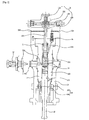
- FIG. 2 is a cross sectional view illustrating a fuel injection pump having a separable plunger according to an exemplary embodiment of the present invention
- FIG. 3 is a view for explaining an operational process of a fuel injection pump having a separable plunger according to the present invention
- FIG. 4 is a view illustrating a combination of an injection section form of a main plunger and a separable plunger corresponding to various cases according to the present invention
- FIG. 5 is a view for explaining a separable plunger according to the present invention.
- a fuel injection pump having a separable plunger is configured to include a main pump casing 10, a barrel 11, a main plunger 12, a separable plunger 13, an elastic member 14, a preliminary fuel injection adjustment means 15, and a main pump fuel adjustment means 16.
- a barrel insertion groove 100 is formed inside, a rotation axis insertion groove 101 is formed in a direction of a barrel insertion groove 100 on an upper surface so as to be connected to an upper portion of the barrel insertion groove 100, a main fuel input hole 102 connected to a fuel inhale hole 17 in a center portion of an outer circumference thereof so as to be connected to the barrel insertion groove 100, and a drain line 103 penetrates one side of an upper portion of the outer circumference connected to the barrel insertion groove 100, and a main fuel outlet 104 formed on the other side of the upper portion of the outer circumference.
- the barrel 11 is inserted and mounted to the barrel insertion groove 100 of the main pump casing 10 and has a main fuel relief plug 110 installed on a center portion of an outer circumference so as to be connected to the main fuel input hole 102, has a plunger coupling hole 111 formed inside, and has a main fuel outlet 112 of which lower portion is connected to the plunger coupling hole 111 and of which upper portion is connected to a lower portion of the main fuel outlet 104 formed on the main pump casing 10.
- the main plunger 12 is slide coupled to the plunger coupling hole 111 of the barrel 11 such that a lower portion thereof protrudes outwardly from a lower portion of the barrel 11 and the main pump casing 10, and an injection timing control spiral step 120 of which lower portion is formed in a spiral shape is formed in an upper portion of the main plunger 12, and a fuel passage 121 is formed on one side of an outer circumference including the injection timing control spiral step 120.
- the separable plunger 13 is slide coupled to the plunger coupling hole 111 formed within the barrel 11 such that a lower portion thereof is supported by an upper portion of the main plunger 12 to enable upward and downward slide movement in association with the main plunger 12, and an injection timing control step 130 of which upper surface is formed in a spiral shape is protrudingly formed on an outer circumference of the separable plunger 13, and a fuel passage 133 is formed on one side of an outer circumference including the injection timing control step 130, and a rotation axis insertion hole 131 is formed in a direction from an upper surface to a lower surface.
- a preliminary injection spiral protrusion 132 may be further formed on an outer circumference thereof and separated from the injection timing adjustment step 130 at a predetermined interval such that a preliminary injection fuel passage 132a is formed between the preliminary injection spiral protrusion 132 and an upper surface of the injection timing adjustment step 130.
- the elastic member 14 has a lower portion elastically supported by the separable plunger 13 and an upper portion inserted to the plunger coupling hole 111 so as to be supported by an upper surface of the plunger coupling hole 111 formed within the barrel 11.
- the fuel injection pump further comprises the preliminary fuel injection adjustment means 15 which is installed on an upper portion of the main pump casing 10 and a lower portion thereof is inserted within the main pump casing 10 and the barrel 11 to be inserted within the separable plunger 13 and slide coupled thereto, thereby rotating the separable plunger 13 to adjust a timing of fuel injection.
- the preliminary fuel injection adjustment means 15 includes a rotation axis 150, a timing adjustment rack 151, a timing pinion 152, and a stop nut 153.
- the rotation axis 150 of the preliminary fuel injection adjustment control means 15 configured as above has a lower portion which is inserted within the main pump casing 10 and the barrel 11 to be slide coupled to an inside of the separable plunger 13, i.e., a rotation axis insertion hole 101 formed in a direction from an upper surface to a lower surface of the separable plunger 13.
- the timing control rack 151 is installed on an upper portion of the rotation axis 150 to be located outside of the main pump casing 10.
- the timing pinion 152 is gear connected to the timing control rack 151.
- the stop nut 153 is screw coupled to an upper end portion of the rotation axis 150.
- the main pump fuel adjustment means 16 comprises a main pump fuel adjustment pinion 160 installed on a lower portion of an outer circumference of the barrel 11 and a main pump fuel adjustment rack 161 gear connected to the main pump fuel adjustment pinion 160.
- the fuel adjustment valve having the separable plunger may further comprise a return prevention valve 18 installed on the main fuel outlet 104, 112 formed on the main pump casing 10 and the barrel 11.
- FIG. 6 is an example view illustrating a form of a pre-injection according to a fuel injection form of a separable plunger according to the present invention.
- fuel is introduced to an inside of the barrel 11, i.e., an inside of the plunger coupling hole 111 of the barrel 11, sequentially through the main fuel input hole 102 and the main fuel relief plug 110 to be in a standby state.
- the fuel introduced to the inside of the plunger coupling hole 111 of the barrel 11 to be in the standby state is compressed at high pressure by the main plunger 12 and the separable plunger 13 which are slide moved and elevated by a cam axis (not shown) which is driven by an engine.
- the main plunger 12 is slide moved and elevated along the plunger coupling hole 111 by a cam axis (not shown) which is driven by an engine, and when the main plunger 12 is elevated as above, by the main plunger 12, the separable plunger 13 is also slid and elevated along the rotation axis 150 and the plunger coupling hole 111 by the main plunger 12.
- the elastic member 14 which elastically supports the separable plunger 13 is in a compressed state by the separable plunger 13, and as the main plunger 12 and the separable plunger 13 are slide moved and elevated, the fuel introduced to the inside of the plunger coupling hole 111 of the barrel 11 sequentially through the main fuel input hole 102 and the main fuel relief plug 110 through the fuel inhale hole 17 is compressed at the high pressure.
- the main plunger 12 and the separable plunger 13 are further elevated along the plunger coupling hole 111 and the rotation axis 150 such that the preliminary injection fuel passage 132a of the separable plunger 13 is positioned on the same plane with the main fuel relief plug 110, and the fuel introduced to the inside of the plunger coupling hole 11 and compressed at the high pressure is preliminarily injected to an inside of a combustion chamber sequentially through the preliminary injection fuel passage 132a, the fuel passage 133 of the separable plunger 13, and the main fuel outlet 112, 104.
- the rotation axis 150 is elevated or lowered by the timing adjustment rack 151 such that a timing point at which the preliminary injection fuel passage 132 is opened is adjusted, thereby adjusting a preliminary injection timing of the fuel.
- the main fuel relief plug 110 is blocked by the injection timing adjustment step 13 of the separable plunger 13 and the injection timing adjustment spiral step 120 of the main plunger 12 such that the fuel is compressed at a gradually increasing high pressure as the separable plunger 13 and the main plunger 12 are elevated.
- the fuel is compressed at the gradually increasing high pressure and, when the injection timing adjustment spiral step 120 of the main plunger 12 is located at an upper portion of the main fuel relief plug 110, fuel within the plunger coupling hole 11 is main injected to the inside of the combustion chamber sequentially through the fuel passage 121 and the main fuel outlet 112, 104.
- the separable plunger 13 and the main plunger 12 are lowered by an elastic force of the elastic member 14 compressed by the separable plunger 13, and as the separable plunger 13 and the main plunger 12 are lowered, remaining fuel is post injected to the inside of the combustion chamber sequentially through the preliminary injection fuel passage 132a and the fuel passage 133 of the separable plunger 13 and the main fuel outlet 112, 104 from a time point at which the preliminary injection fuel passage 132a of the separable plunger 13 is located below the main fuel relief plug 110.
- the fuel injection valve having the separable plunger according to the present invention is provided with, in addition to the main plunger 12, the separable plunger 13, which is slide moved upward and downward in association with the main plunger 12 such that fuel may be preliminary injected through the separable plunger 13 before the fuel is compressed and main injected by the main plunger 12, thereby enabling injection warming up and, at the same time, post injecting the remaining fuel after the main injection through the separable plunger 13, so that combustion performance may be improved, fuel consumption ratio may be decreased, and exhaust gas may be reduced, thereby improving an overall engine performance.
- the rotation axis 150 of the preliminary fuel injection adjustment means 15 is moved upward and downward to easily adjust the fuel injection timing from an external as well as the preliminary fuel injection adjustment means 15 is installed on the upper portion of the main pump casing, thereby being advantageous in that an operation for adjusting the fuel injection timing is very convenient and a very easy repair is rendered.
- the fuel injection valve having the separable plunger according to the present invention is provided with the separable plunger 13 on which the injection timing adjustment step 130 of which upper portion is formed in a spiral shape is formed such that a vertical height of the separable plunger 13 may be adjusted by using the preliminary fuel injection adjustment means 15, thereby adjusting various time points of fuel injection timing.
Landscapes
- Engineering & Computer Science (AREA)
- Chemical & Material Sciences (AREA)
- Combustion & Propulsion (AREA)
- Mechanical Engineering (AREA)
- General Engineering & Computer Science (AREA)
- Fuel-Injection Apparatus (AREA)
Abstract
an elastic member having a lower portion elastically supported by the separable plunger and an upper portion inserted within the barrel to be supported by an upper surface of the barrel.
Description
- The present invention relates to a fuel injection pump having a separable plunger and, more particularly, to a fuel injection valve having a separable plunger, being capable of not only easily adjusting a timing and a form of fuel injection with a simple structure but also enabling fine pre-injection of an engine at high pressure, thereby assisting in warming up within an engine cylinder, such that complete combustion may occur when main fuel is entered.
- Hereinafter, a background art and a problem thereof will be described with reference to drawings.
-
FIG. 1 is an internal cross sectional view for explaining a conventional fuel injection pump, and referring toFIG. 2 , a general conventional fuel injection pump includes apump casing 10, abarrel 11, and aplunger 12. - The
pump casing 10 of the conventional fuel injection pump configured as above has abarrel insertion groove 100 formed inside and afuel input hole 102 connected to a fuel inlet penetrates through a center portion of an outer circumference thereof so as to be connected to thebarrel insertion groove 100. - The
barrel 11 is mounted to thebarrel insertion groove 100 of thepump casing 10 and afuel relief plug 110 is installed on a center portion of an outer circumference thereof so as to be connected to thefuel inlet hole 102 and aplunger coupling hole 111 is formed inside. - The
plunger 12 is slide coupled to theplunger coupling hole 111 of thebarrel 11 so that a lower portion thereof is protruded outwardly from thebarrel 11 and a lower portion of thepump casing 120. - The general fuel injection pump of a diesel engine configured as above injects fuel by the
plunger 12 respectively installed on each cylinder. Thus, fuel injection may have a combustion pattern corresponding to one cycle by a cam, and only a volume is determined in theplunger 12 such that a value thereof cannot be varied during an operation in order to assist in fine injection and incomplete combustion prior to combustion, thereby requiring a separate variable fuel injection timing adjustment apparatus in order to change a fuel injection timing during the operation. In other words, in case of a mechanic type apparatus, thebarrel 11 is inserted inside to move thebarrel 11 upward and downward to adjust the injection timing and, in case of an electronic type, a crank angle is read in a form of a common rail to perform the fuel injection at a required timing. - However, a variable fuel injection timing apparatus as above is not only very expensive but also adjustment or control thereof is very difficult, and only a volume of fuel can be controlled by forming a spiral groove (helices) on the
plunger 12 such that a main volume of engine injection fuel is injected in only a predetermined pattern. - Also, in the conventional fuel injection pump as above, each one
plunger 12 is operated within the pump to form a cycle such that any different combustion pattern cannot be implemented without an additional apparatus, and a fuel amount and the injection timing may be adjusted by oneplunger 12 such that various fuel injection patterns are difficult to access. Such pattern has a problem in that an engine operation as well as a fuel change and a timing thereof need to be adjusted very carefully during an operation, and it is difficult for every load area to show an optimal performance because all areas of an engine load are coped with oneplunger 12 within one fuel injection pump, and a load is not actively coped with, thereby causing a problem of fuel efficiency and a problem of harmful gas discharge. - Therefore, an objective of the present invention is to provide a fuel injection pump having a separable plunger in which two plungers are installed in one fuel injection pump such that two plungers may have different combustion patterns in one cycle according to a fuel cam, thereby achieving improved engine performance through diversification of a fuel injection pattern, and a fuel injection amount may be adjusted through individual adjustment of whether to operate or not the plunger within the fuel injection pump according to an engine load, and fuel may be completely combusted through a warming up and pre-injection for complete combustion within a form of one cycle of the fuel, thereby being capable of removing a contaminated material within a combustion chamber, reducing discharged harmful gas, and adjusting a fuel injection timing according to an engine combustion pattern at a timing of an initial preliminary injection.
- The present invention for achieving the above objective provides a fuel injection pump having a separable plunger, wherein a barrel is installed within a main pump casing, a main plunger of which lower portion is protruded in a downward direction of the barrel is slide coupled to an inside of the barrel, and a main fuel outlet is formed on the main pump casing and the barrel to be connected to each other, so that the main plunger is slide moved upward and downward along the barrel to compress fuel introduced within the barrel through a main fuel input hole and a main fuel relief plug to be provided to a fuel injection hole through the main fuel outlet, the fuel injection pump including: a separable plunger of which outer circumference is slide coupled to an inside of the barrel such that a lower portion thereof is supported by an upper portion of the main plunger to enable upward and downward slide movement in association with the main plunger, wherein an injection timing control spiral step of which upper surface is formed in a spiral shape is protrudingly formed on the outer circumference thereof and a fuel passage is formed on one side of the outer circumference thereof including the injection timing control spiral step and an elastic member having a lower portion elastically supported by the separable plunger and an upper portion inserted within the barrel to be supported by an upper surface of the barrel.
- The fuel injection pump may further include a preliminary fuel injection adjustment means installed on an upper portion of the main pump casing and having a lower portion thereof inserted within the main pump casing and the barrel to be inserted within the separable plunger and slide coupled thereto, thereby rotating the separable plunger adjust a timing of fuel injection.
- Here, the preliminary fuel injection adjustment means may include a rotation axis of which lower portion is inserted within the main pump casing and the barrel to be inserted and slide coupled to an inside of the separable plunger; a timing adjustment rack installed on an upper portion of the rotation axis to be located outside of the main pump casing; a timing pinion gear connected to the timing control rack; and a stop nut screw coupled to an upper end portion of the rotation axis.
- Also, the separable plunger may further include a preliminary injection spiral protrusion protrudingly formed on an outer circumference thereof and separated from the injection timing adjustment step at a predetermined interval such that a preliminary injection fuel passage is formed between the preliminary injection spiral protrusion and an upper surface of the injection timing adjustment step.
- As described above, the fuel injection valve having the separable plunger according to the present invention is provided with, in addition to the main plunger, the separable plunger, which is slide moved upward and downward in association with the main plunger such that fuel may be preliminary injected through the separable plunger before the fuel is compressed and main injected by the main plunger, thereby enabling injection warming up and, at the same time, post injecting the remaining fuel after the main injection through the separable plunger, so that combustion performance may be improved, fuel consumption ratio may be decreased, and exhaust gas may be reduced, thereby improving an overall engine performance.
- Also, in the fuel injection valve having the separable plunger according to the present invention, the rotation axis of the preliminary fuel injection adjustment means is moved upward and downward to easily adjust the fuel injection timing from an external as well as the preliminary fuel injection adjustment means is installed on the upper portion of the main pump casing, thereby achieving an effect that an operation for adjusting the fuel injection timing is very convenient and a very easy repair is rendered.
- Further, the fuel injection valve having the separable plunger according to the present invention is provided with the separable plunger on which the injection timing adjustment step of which upper portion is formed in a spiral shape is formed such that a vertical height of the separable plunger may be adjusted by using the preliminary fuel injection adjustment means, thereby adjusting various time points of fuel injection timing.
-
-
FIG. 1 is an internal cross sectional view for explaining a conventional fuel injection pump. -
FIG. 2 is a cross sectional view illustrating a fuel injection pump having a separable plunger according to an exemplary embodiment of the present invention. -
FIG. 3 is a view for explaining an operational process of a fuel injection pump having a separable plunger according to the present invention. -
FIG. 4 is a view illustrating a combination of an injection section form of a main plunger and a separable plunger corresponding to various cases according to the present invention. -
FIG. 5 is a view for explaining a separable plunger according to the present invention. -
FIG. 6 is an example view illustrating a form of a pre-injection according to a fuel injection form of a separable plunger according to the present invention. -
- (10) : main pump casing (11) : barrel
- (12) : main plunger (13) : separable plunger
- (14) : elastic member (15) : preliminary fuel injection adjustment means (16) : main pump fuel adjustment means
- Hereinafter, exemplary embodiments of the present invention will be described herein below with reference to the accompanying drawings. For illustrative purposes, it should be noted that like numbers refer to like elements of a conventional fuel injection pump.
-
FIG. 2 is a cross sectional view illustrating a fuel injection pump having a separable plunger according to an exemplary embodiment of the present invention,FIG. 3 is a view for explaining an operational process of a fuel injection pump having a separable plunger according to the present invention,FIG. 4 is a view illustrating a combination of an injection section form of a main plunger and a separable plunger corresponding to various cases according to the present invention, andFIG. 5 is a view for explaining a separable plunger according to the present invention. - Referring to
FIGS. 2 through 5 , a fuel injection pump having a separable plunger is configured to include amain pump casing 10, abarrel 11, amain plunger 12, aseparable plunger 13, anelastic member 14, a preliminary fuel injection adjustment means 15, and a main pump fuel adjustment means 16. - In the
main pump casing 10 of the fuel injection pump having the separable plunger according to an exemplary embodiment of the present invention configured as above, abarrel insertion groove 100 is formed inside, a rotationaxis insertion groove 101 is formed in a direction of abarrel insertion groove 100 on an upper surface so as to be connected to an upper portion of thebarrel insertion groove 100, a mainfuel input hole 102 connected to afuel inhale hole 17 in a center portion of an outer circumference thereof so as to be connected to thebarrel insertion groove 100, and adrain line 103 penetrates one side of an upper portion of the outer circumference connected to thebarrel insertion groove 100, and amain fuel outlet 104 formed on the other side of the upper portion of the outer circumference. - The
barrel 11 is inserted and mounted to thebarrel insertion groove 100 of themain pump casing 10 and has a mainfuel relief plug 110 installed on a center portion of an outer circumference so as to be connected to the mainfuel input hole 102, has aplunger coupling hole 111 formed inside, and has amain fuel outlet 112 of which lower portion is connected to theplunger coupling hole 111 and of which upper portion is connected to a lower portion of themain fuel outlet 104 formed on themain pump casing 10. - The
main plunger 12 is slide coupled to theplunger coupling hole 111 of thebarrel 11 such that a lower portion thereof protrudes outwardly from a lower portion of thebarrel 11 and themain pump casing 10, and an injection timing controlspiral step 120 of which lower portion is formed in a spiral shape is formed in an upper portion of themain plunger 12, and afuel passage 121 is formed on one side of an outer circumference including the injection timing controlspiral step 120. - The
separable plunger 13 is slide coupled to theplunger coupling hole 111 formed within thebarrel 11 such that a lower portion thereof is supported by an upper portion of themain plunger 12 to enable upward and downward slide movement in association with themain plunger 12, and an injectiontiming control step 130 of which upper surface is formed in a spiral shape is protrudingly formed on an outer circumference of theseparable plunger 13, and afuel passage 133 is formed on one side of an outer circumference including the injectiontiming control step 130, and a rotationaxis insertion hole 131 is formed in a direction from an upper surface to a lower surface. Also, in theseparable plunger 13, a preliminary injectionspiral protrusion 132 may be further formed on an outer circumference thereof and separated from the injectiontiming adjustment step 130 at a predetermined interval such that a preliminaryinjection fuel passage 132a is formed between the preliminary injectionspiral protrusion 132 and an upper surface of the injectiontiming adjustment step 130. - The
elastic member 14 has a lower portion elastically supported by theseparable plunger 13 and an upper portion inserted to theplunger coupling hole 111 so as to be supported by an upper surface of theplunger coupling hole 111 formed within thebarrel 11. - The fuel injection pump further comprises the preliminary fuel injection adjustment means 15 which is installed on an upper portion of the
main pump casing 10 and a lower portion thereof is inserted within themain pump casing 10 and thebarrel 11 to be inserted within theseparable plunger 13 and slide coupled thereto, thereby rotating theseparable plunger 13 to adjust a timing of fuel injection. - A configuration of the preliminary fuel injection adjust means 15 will be described in detail; the preliminary fuel injection adjustment means 15 includes a
rotation axis 150, atiming adjustment rack 151, atiming pinion 152, and astop nut 153. - The
rotation axis 150 of the preliminary fuel injection adjustment control means 15 configured as above has a lower portion which is inserted within themain pump casing 10 and thebarrel 11 to be slide coupled to an inside of theseparable plunger 13, i.e., a rotationaxis insertion hole 101 formed in a direction from an upper surface to a lower surface of theseparable plunger 13. Also, thetiming control rack 151 is installed on an upper portion of therotation axis 150 to be located outside of themain pump casing 10. Also, thetiming pinion 152 is gear connected to thetiming control rack 151. Thestop nut 153 is screw coupled to an upper end portion of therotation axis 150. - The main pump fuel adjustment means 16 comprises a main pump
fuel adjustment pinion 160 installed on a lower portion of an outer circumference of thebarrel 11 and a main pumpfuel adjustment rack 161 gear connected to the main pumpfuel adjustment pinion 160. - Also, the fuel adjustment valve having the separable plunger may further comprise a
return prevention valve 18 installed on themain fuel outlet main pump casing 10 and thebarrel 11. - Referring now to
FIGS. 2 through 6 , an operational effect of the fuel injection pump having the separable plunger according to an exemplary embodiment of the present invention is described below. -
FIG. 6 is an example view illustrating a form of a pre-injection according to a fuel injection form of a separable plunger according to the present invention. - Referring to
FIGS. 2 through 6 , in the fuel adjustment pump having the separable plunger according to the present invention, fuel is introduced to an inside of thebarrel 11, i.e., an inside of theplunger coupling hole 111 of thebarrel 11, sequentially through the mainfuel input hole 102 and the mainfuel relief plug 110 to be in a standby state. - As above, the fuel introduced to the inside of the
plunger coupling hole 111 of thebarrel 11 to be in the standby state is compressed at high pressure by themain plunger 12 and theseparable plunger 13 which are slide moved and elevated by a cam axis (not shown) which is driven by an engine. - In other words, the
main plunger 12 is slide moved and elevated along theplunger coupling hole 111 by a cam axis (not shown) which is driven by an engine, and when themain plunger 12 is elevated as above, by themain plunger 12, theseparable plunger 13 is also slid and elevated along therotation axis 150 and theplunger coupling hole 111 by themain plunger 12. Here, theelastic member 14 which elastically supports theseparable plunger 13 is in a compressed state by theseparable plunger 13, and as themain plunger 12 and theseparable plunger 13 are slide moved and elevated, the fuel introduced to the inside of theplunger coupling hole 111 of thebarrel 11 sequentially through the mainfuel input hole 102 and the mainfuel relief plug 110 through thefuel inhale hole 17 is compressed at the high pressure. - Here, the
main plunger 12 and theseparable plunger 13 are further elevated along theplunger coupling hole 111 and therotation axis 150 such that the preliminaryinjection fuel passage 132a of theseparable plunger 13 is positioned on the same plane with the mainfuel relief plug 110, and the fuel introduced to the inside of theplunger coupling hole 11 and compressed at the high pressure is preliminarily injected to an inside of a combustion chamber sequentially through the preliminaryinjection fuel passage 132a, thefuel passage 133 of theseparable plunger 13, and themain fuel outlet - Meanwhile, when the
timing pinion 152 of the preliminary fuel injection adjustment means 15 is rotated, therotation axis 150 is elevated or lowered by thetiming adjustment rack 151 such that a timing point at which the preliminaryinjection fuel passage 132 is opened is adjusted, thereby adjusting a preliminary injection timing of the fuel. - When the
main plunger 12 and theseparable plunger 13 are further elevated after the compressed fuel is preliminary injected, the mainfuel relief plug 110 is blocked by the injectiontiming adjustment step 13 of theseparable plunger 13 and the injection timing adjustmentspiral step 120 of themain plunger 12 such that the fuel is compressed at a gradually increasing high pressure as theseparable plunger 13 and themain plunger 12 are elevated. - As above, as the
separable plunger 13 and themain plunger 12 are elevated, the fuel is compressed at the gradually increasing high pressure and, when the injection timing adjustmentspiral step 120 of themain plunger 12 is located at an upper portion of the mainfuel relief plug 110, fuel within theplunger coupling hole 11 is main injected to the inside of the combustion chamber sequentially through thefuel passage 121 and themain fuel outlet - After the main injection of the fuel is completed, the
separable plunger 13 and themain plunger 12 are lowered by an elastic force of theelastic member 14 compressed by theseparable plunger 13, and as theseparable plunger 13 and themain plunger 12 are lowered, remaining fuel is post injected to the inside of the combustion chamber sequentially through the preliminaryinjection fuel passage 132a and thefuel passage 133 of theseparable plunger 13 and themain fuel outlet injection fuel passage 132a of theseparable plunger 13 is located below the mainfuel relief plug 110. - As described above, the fuel injection valve having the separable plunger according to the present invention is provided with, in addition to the
main plunger 12, theseparable plunger 13, which is slide moved upward and downward in association with themain plunger 12 such that fuel may be preliminary injected through theseparable plunger 13 before the fuel is compressed and main injected by themain plunger 12, thereby enabling injection warming up and, at the same time, post injecting the remaining fuel after the main injection through theseparable plunger 13, so that combustion performance may be improved, fuel consumption ratio may be decreased, and exhaust gas may be reduced, thereby improving an overall engine performance. - Also, in the fuel injection valve having the separable plunger according to the present invention, the
rotation axis 150 of the preliminary fuel injection adjustment means 15 is moved upward and downward to easily adjust the fuel injection timing from an external as well as the preliminary fuel injection adjustment means 15 is installed on the upper portion of the main pump casing, thereby being advantageous in that an operation for adjusting the fuel injection timing is very convenient and a very easy repair is rendered. - Further, the fuel injection valve having the separable plunger according to the present invention is provided with the
separable plunger 13 on which the injection timingadjustment step 130 of which upper portion is formed in a spiral shape is formed such that a vertical height of theseparable plunger 13 may be adjusted by using the preliminary fuel injection adjustment means 15, thereby adjusting various time points of fuel injection timing. - The present invention is not limited to particular preferable exemplary embodiments described above and it will be understood by those of ordinary skill in the art that various modifications may be made without departing from the spirit and scope of the present invention as defined by the following claims.
Claims (4)
- A fuel injection pump having a separable plunger, wherein a barrel is installed within a main pump casing, a main plunger of which lower portion is protruded in a downward direction of the barrel is slide coupled to an inside of the barrel, and a main fuel outlet is formed on the main pump casing and the barrel to be connected to each other, so that the main plunger is slide moved upward and downward along the barrel to compress fuel introduced within the barrel through a main fuel input hole and a main fuel relief plug to be provided to a fuel injection hole through the main fuel outlet, the fuel injection pump comprising:a separable plunger of which outer circumference is slide coupled to an inside of the barrel such that a lower portion thereof is supported by an upper portion of the main plunger to enable upward and downward slide movement in association with the main plunger, wherein an injection timing control spiral step of which upper surface is formed in a spiral shape is protrudingly formed on the outer circumference thereof and a fuel passage is formed on one side of the outer circumference thereof including the injection timing control spiral step; andan elastic member having a lower portion elastically supported by the separable plunger and an upper portion inserted within the barrel to be supported by an upper surface of the barrel.
- The fuel injection pump of claim 1, further comprising:a preliminary fuel injection adjustment means installed on an upper portion of the main pump casing and having a lower portion thereof inserted within the main pump casing and the barrel to be inserted within the separable plunger and slide coupled thereto, thereby rotating the separable plunger adjust a timing of fuel injection
- The fuel injection pump of claim 2, wherein the preliminary fuel injection adjustment means comprises:a rotation axis of which lower portion is inserted within the main pump casing and the barrel to be inserted and slide coupled to an inside of the separable plunger;a timing adjustment rack installed on an upper portion of the rotation axis to be located outside of the main pump casing;a timing pinion gear connected to the timing control rack; anda stop nut screw coupled to an upper end portion of the rotation axis.
- The fuel injection pump of claim 1 through claim 3, the separable plunger further comprises:a preliminary injection spiral protrusion protrudingly formed on an outer circumference thereof and separated from the injection timing adjustment step at a predetermined interval such that a preliminary injection fuel passage is formed between the preliminary injection spiral protrusion and an upper surface of the injection timing adjustment step.
Applications Claiming Priority (2)
| Application Number | Priority Date | Filing Date | Title |
|---|---|---|---|
| KR1020100054494A KR101139128B1 (en) | 2010-06-09 | 2010-06-09 | Diesel engine with separated plunger for fuel inject pump system |
| PCT/KR2010/007412 WO2011155671A1 (en) | 2010-06-09 | 2010-10-27 | Fuel injection pump having a separable plunger |
Publications (3)
| Publication Number | Publication Date |
|---|---|
| EP2581598A1 true EP2581598A1 (en) | 2013-04-17 |
| EP2581598A4 EP2581598A4 (en) | 2014-04-30 |
| EP2581598B1 EP2581598B1 (en) | 2016-10-19 |
Family
ID=45098255
Family Applications (1)
| Application Number | Title | Priority Date | Filing Date |
|---|---|---|---|
| EP10852953.8A Not-in-force EP2581598B1 (en) | 2010-06-09 | 2010-10-27 | Fuel injection pump having a separable plunger |
Country Status (7)
| Country | Link |
|---|---|
| US (1) | US9074567B2 (en) |
| EP (1) | EP2581598B1 (en) |
| JP (1) | JP5593441B2 (en) |
| KR (1) | KR101139128B1 (en) |
| CN (1) | CN202914216U (en) |
| DK (1) | DK2581598T3 (en) |
| WO (1) | WO2011155671A1 (en) |
Families Citing this family (3)
| Publication number | Priority date | Publication date | Assignee | Title |
|---|---|---|---|---|
| KR101727436B1 (en) | 2016-10-13 | 2017-04-14 | 변용선 | Assembly tool to Plunger of internal combustion engine Injector |
| CN110685842B (en) * | 2019-11-21 | 2021-05-04 | 中船动力有限公司 | Variable oil injection timing oil injection pump of diesel engine |
| JP7433079B2 (en) * | 2020-02-21 | 2024-02-19 | 三菱重工エンジン&ターボチャージャ株式会社 | Cam, fuel injection pump and engine |
Family Cites Families (18)
| Publication number | Priority date | Publication date | Assignee | Title |
|---|---|---|---|---|
| US2185144A (en) * | 1937-05-27 | 1939-12-26 | Timken Roller Bearing Co | Fuel injection pump |
| US2455571A (en) * | 1944-11-11 | 1948-12-07 | Timken Roller Bearing Co | Fuel injection pump |
| EP0117219A3 (en) * | 1983-02-17 | 1986-08-06 | Ail Corporation | Arrangement for adjusting axial positioning of injection barrel in fuel injection pump |
| DE3330771A1 (en) * | 1983-08-26 | 1985-03-14 | Robert Bosch Gmbh, 7000 Stuttgart | FUEL INJECTION DEVICE WITH AUXILIARY PUMP FOR PRIME AND MAIN INJECTION |
| JPH0447418Y2 (en) * | 1985-07-24 | 1992-11-09 | ||
| JPS6235057A (en) * | 1985-08-09 | 1987-02-16 | Hino Motors Ltd | Fuel injection pump |
| DE3731817A1 (en) * | 1987-09-22 | 1989-03-30 | Hatz Motoren | FUEL INJECTION PUMP FOR INTERNAL COMBUSTION ENGINES |
| US4861243A (en) * | 1988-04-08 | 1989-08-29 | Ford Motor Company | Diesel fuel injection pump with variable injection timing |
| JPH0243460U (en) * | 1988-09-19 | 1990-03-26 | ||
| GB8823453D0 (en) * | 1988-10-06 | 1988-11-16 | Lucas Ind Plc | Pump |
| JPH0754617Y2 (en) * | 1989-08-01 | 1995-12-18 | 株式会社小松製作所 | Diesel engine fuel injector |
| JP2566474Y2 (en) * | 1991-01-19 | 1998-03-25 | 株式会社小松製作所 | Fuel injection device |
| JPH0777124A (en) | 1993-09-09 | 1995-03-20 | Zexel Corp | Pilot injection controller |
| JPH0777131A (en) * | 1993-09-10 | 1995-03-20 | Nippondenso Co Ltd | Fuel injection pump |
| JPH08100740A (en) * | 1994-09-30 | 1996-04-16 | Zexel Corp | Pilot injection amount control mechanism of fuel injection device and method for controlling pilot injection amount |
| US5566660A (en) * | 1995-04-13 | 1996-10-22 | Caterpillar Inc. | Fuel injection rate shaping apparatus for a unit fuel injector |
| SE508545C2 (en) * | 1997-04-08 | 1998-10-12 | Volvo Penta Ab | Procedure for calibration of injection time |
| KR200238054Y1 (en) * | 1997-12-31 | 2001-11-22 | 이계안 | Injection timing plunger of injection pump |
-
2010
- 2010-06-09 KR KR1020100054494A patent/KR101139128B1/en not_active IP Right Cessation
- 2010-10-27 WO PCT/KR2010/007412 patent/WO2011155671A1/en active Application Filing
- 2010-10-27 US US13/702,096 patent/US9074567B2/en active Active
- 2010-10-27 CN CN201090001526.7U patent/CN202914216U/en not_active Expired - Lifetime
- 2010-10-27 JP JP2013510010A patent/JP5593441B2/en not_active Expired - Fee Related
- 2010-10-27 EP EP10852953.8A patent/EP2581598B1/en not_active Not-in-force
- 2010-10-27 DK DK10852953.8T patent/DK2581598T3/en active
Non-Patent Citations (2)
| Title |
|---|
| No further relevant documents disclosed * |
| See also references of WO2011155671A1 * |
Also Published As
| Publication number | Publication date |
|---|---|
| EP2581598A4 (en) | 2014-04-30 |
| CN202914216U (en) | 2013-05-01 |
| JP5593441B2 (en) | 2014-09-24 |
| DK2581598T3 (en) | 2017-01-16 |
| WO2011155671A1 (en) | 2011-12-15 |
| KR20110134745A (en) | 2011-12-15 |
| US20130074811A1 (en) | 2013-03-28 |
| EP2581598B1 (en) | 2016-10-19 |
| US9074567B2 (en) | 2015-07-07 |
| JP2013526670A (en) | 2013-06-24 |
| KR101139128B1 (en) | 2012-04-30 |
Similar Documents
| Publication | Publication Date | Title |
|---|---|---|
| EP2578867A1 (en) | Dual fuel injection valve apparatus including a hybrid nozzle for diesel and gas engines | |
| EP2581598B1 (en) | Fuel injection pump having a separable plunger | |
| EP1930582A3 (en) | Fuel injection apparatus for engines and method of operating the apparatus | |
| EP1333173B1 (en) | Accumulator distribution type fuel injection pump | |
| EP2634414B1 (en) | Fuel-injection valve for an internal combustion engine | |
| EP2351929A2 (en) | Apparatus for preventing cavitation damage to a diesel engine fuel injection pump | |
| KR101440174B1 (en) | Multi Fuel Inection Apparatus of Diesel Engine | |
| KR101129887B1 (en) | Dual fuel injection valve | |
| CN207454152U (en) | Injection pump and diesel engine | |
| CN101000025B (en) | Plunger even member adopting shoe-shape oil supplying law | |
| CN115003905B (en) | Cam, fuel injection pump and engine | |
| KR20150066213A (en) | The hydraulic fuel injection system the fuel injection pump for diesel engine | |
| CN203175779U (en) | Ultrahigh pressure axial plunger-type fuel pump | |
| KR20160075882A (en) | Fuel injection device with multi plunger of Diesel Engine | |
| CN107489571B (en) | Automatic exhaust method of electric control monoblock pump | |
| JP2015187405A (en) | Fuel injection system of dual fuel engine | |
| CN114941600A (en) | Special direct-control plunger component for switch valve | |
| CN2839603Y (en) | Diesel engine double-spring fuel-injector | |
| RU2369768C1 (en) | High-pressure fuel pump (hpfp) section | |
| KR20150066896A (en) | The hydraulic fuel injection system for diesel engine | |
| KR20160060203A (en) | Diesel Engine Fuel Injection Pump With Fuel Injection Controller | |
| DE102012218766A1 (en) | Method for operating fuel high pressure pump of common rail system of internal combustion engine of motor car, involves providing pumping cycles in predetermined period, and providing number of switching of inlet valve between states | |
| KR20020051618A (en) | Injector for direct injection type diesel engine | |
| JP2015187406A (en) | Injector for micro pilot injection of dual fuel engine | |
| KR20150066897A (en) | The hydraulic fuel injection system the fuel injection valve for diesel engine |
Legal Events
| Date | Code | Title | Description |
|---|---|---|---|
| PUAI | Public reference made under article 153(3) epc to a published international application that has entered the european phase |
Free format text: ORIGINAL CODE: 0009012 |
|
| 17P | Request for examination filed |
Effective date: 20121129 |
|
| AK | Designated contracting states |
Kind code of ref document: A1 Designated state(s): AL AT BE BG CH CY CZ DE DK EE ES FI FR GB GR HR HU IE IS IT LI LT LU LV MC MK MT NL NO PL PT RO RS SE SI SK SM TR |
|
| RIN1 | Information on inventor provided before grant (corrected) |
Inventor name: KIM, JU-TAE Inventor name: HEO, KWANG-CHEOL Inventor name: HA, EUN Inventor name: NO, BEOM-YONG Inventor name: KIM, EUNG-SUNG Inventor name: PARK, DEUK-JIN Inventor name: KIM, JONG-SUK Inventor name: JUNG, KANG-YUN |
|
| DAX | Request for extension of the european patent (deleted) | ||
| A4 | Supplementary search report drawn up and despatched |
Effective date: 20140327 |
|
| RIC1 | Information provided on ipc code assigned before grant |
Ipc: F02M 59/44 20060101ALI20140321BHEP Ipc: F02M 59/20 20060101ALI20140321BHEP Ipc: F02M 59/26 20060101AFI20140321BHEP |
|
| REG | Reference to a national code |
Ref country code: DE Ref legal event code: R079 Ref document number: 602010037393 Country of ref document: DE Free format text: PREVIOUS MAIN CLASS: F02M0059260000 Ipc: F02M0059280000 |
|
| RIC1 | Information provided on ipc code assigned before grant |
Ipc: F02M 59/28 20060101AFI20160205BHEP Ipc: F02M 59/44 20060101ALI20160205BHEP Ipc: F02M 59/26 20060101ALI20160205BHEP |
|
| GRAP | Despatch of communication of intention to grant a patent |
Free format text: ORIGINAL CODE: EPIDOSNIGR1 |
|
| INTG | Intention to grant announced |
Effective date: 20160329 |
|
| GRAJ | Information related to disapproval of communication of intention to grant by the applicant or resumption of examination proceedings by the epo deleted |
Free format text: ORIGINAL CODE: EPIDOSDIGR1 |
|
| INTC | Intention to grant announced (deleted) | ||
| GRAR | Information related to intention to grant a patent recorded |
Free format text: ORIGINAL CODE: EPIDOSNIGR71 |
|
| GRAS | Grant fee paid |
Free format text: ORIGINAL CODE: EPIDOSNIGR3 |
|
| GRAA | (expected) grant |
Free format text: ORIGINAL CODE: 0009210 |
|
| AK | Designated contracting states |
Kind code of ref document: B1 Designated state(s): AL AT BE BG CH CY CZ DE DK EE ES FI FR GB GR HR HU IE IS IT LI LT LU LV MC MK MT NL NO PL PT RO RS SE SI SK SM TR |
|
| INTG | Intention to grant announced |
Effective date: 20160909 |
|
| REG | Reference to a national code |
Ref country code: GB Ref legal event code: FG4D |
|
| REG | Reference to a national code |
Ref country code: CH Ref legal event code: EP |
|
| REG | Reference to a national code |
Ref country code: AT Ref legal event code: REF Ref document number: 838576 Country of ref document: AT Kind code of ref document: T Effective date: 20161115 |
|
| REG | Reference to a national code |
Ref country code: IE Ref legal event code: FG4D |
|
| REG | Reference to a national code |
Ref country code: DE Ref legal event code: R096 Ref document number: 602010037393 Country of ref document: DE |
|
| REG | Reference to a national code |
Ref country code: DK Ref legal event code: T3 Effective date: 20170112 |
|
| REG | Reference to a national code |
Ref country code: NL Ref legal event code: FP |
|
| REG | Reference to a national code |
Ref country code: LT Ref legal event code: MG4D |
|
| PG25 | Lapsed in a contracting state [announced via postgrant information from national office to epo] |
Ref country code: LV Free format text: LAPSE BECAUSE OF FAILURE TO SUBMIT A TRANSLATION OF THE DESCRIPTION OR TO PAY THE FEE WITHIN THE PRESCRIBED TIME-LIMIT Effective date: 20161019 Ref country code: BE Free format text: LAPSE BECAUSE OF NON-PAYMENT OF DUE FEES Effective date: 20161031 |
|
| REG | Reference to a national code |
Ref country code: AT Ref legal event code: MK05 Ref document number: 838576 Country of ref document: AT Kind code of ref document: T Effective date: 20161019 Ref country code: CH Ref legal event code: NV Representative=s name: BOVARD AG PATENT- UND MARKENANWAELTE, CH |
|
| PG25 | Lapsed in a contracting state [announced via postgrant information from national office to epo] |
Ref country code: GR Free format text: LAPSE BECAUSE OF FAILURE TO SUBMIT A TRANSLATION OF THE DESCRIPTION OR TO PAY THE FEE WITHIN THE PRESCRIBED TIME-LIMIT Effective date: 20170120 Ref country code: NO Free format text: LAPSE BECAUSE OF FAILURE TO SUBMIT A TRANSLATION OF THE DESCRIPTION OR TO PAY THE FEE WITHIN THE PRESCRIBED TIME-LIMIT Effective date: 20170119 Ref country code: SE Free format text: LAPSE BECAUSE OF FAILURE TO SUBMIT A TRANSLATION OF THE DESCRIPTION OR TO PAY THE FEE WITHIN THE PRESCRIBED TIME-LIMIT Effective date: 20161019 Ref country code: LT Free format text: LAPSE BECAUSE OF FAILURE TO SUBMIT A TRANSLATION OF THE DESCRIPTION OR TO PAY THE FEE WITHIN THE PRESCRIBED TIME-LIMIT Effective date: 20161019 |
|
| PG25 | Lapsed in a contracting state [announced via postgrant information from national office to epo] |
Ref country code: IS Free format text: LAPSE BECAUSE OF FAILURE TO SUBMIT A TRANSLATION OF THE DESCRIPTION OR TO PAY THE FEE WITHIN THE PRESCRIBED TIME-LIMIT Effective date: 20170219 Ref country code: HR Free format text: LAPSE BECAUSE OF FAILURE TO SUBMIT A TRANSLATION OF THE DESCRIPTION OR TO PAY THE FEE WITHIN THE PRESCRIBED TIME-LIMIT Effective date: 20161019 Ref country code: BE Free format text: LAPSE BECAUSE OF FAILURE TO SUBMIT A TRANSLATION OF THE DESCRIPTION OR TO PAY THE FEE WITHIN THE PRESCRIBED TIME-LIMIT Effective date: 20161019 Ref country code: RS Free format text: LAPSE BECAUSE OF FAILURE TO SUBMIT A TRANSLATION OF THE DESCRIPTION OR TO PAY THE FEE WITHIN THE PRESCRIBED TIME-LIMIT Effective date: 20161019 Ref country code: PL Free format text: LAPSE BECAUSE OF FAILURE TO SUBMIT A TRANSLATION OF THE DESCRIPTION OR TO PAY THE FEE WITHIN THE PRESCRIBED TIME-LIMIT Effective date: 20161019 Ref country code: PT Free format text: LAPSE BECAUSE OF FAILURE TO SUBMIT A TRANSLATION OF THE DESCRIPTION OR TO PAY THE FEE WITHIN THE PRESCRIBED TIME-LIMIT Effective date: 20170220 Ref country code: AT Free format text: LAPSE BECAUSE OF FAILURE TO SUBMIT A TRANSLATION OF THE DESCRIPTION OR TO PAY THE FEE WITHIN THE PRESCRIBED TIME-LIMIT Effective date: 20161019 Ref country code: ES Free format text: LAPSE BECAUSE OF FAILURE TO SUBMIT A TRANSLATION OF THE DESCRIPTION OR TO PAY THE FEE WITHIN THE PRESCRIBED TIME-LIMIT Effective date: 20161019 |
|
| REG | Reference to a national code |
Ref country code: DE Ref legal event code: R097 Ref document number: 602010037393 Country of ref document: DE |
|
| REG | Reference to a national code |
Ref country code: IE Ref legal event code: MM4A |
|
| PG25 | Lapsed in a contracting state [announced via postgrant information from national office to epo] |
Ref country code: MC Free format text: LAPSE BECAUSE OF FAILURE TO SUBMIT A TRANSLATION OF THE DESCRIPTION OR TO PAY THE FEE WITHIN THE PRESCRIBED TIME-LIMIT Effective date: 20161019 Ref country code: RO Free format text: LAPSE BECAUSE OF FAILURE TO SUBMIT A TRANSLATION OF THE DESCRIPTION OR TO PAY THE FEE WITHIN THE PRESCRIBED TIME-LIMIT Effective date: 20161019 Ref country code: EE Free format text: LAPSE BECAUSE OF FAILURE TO SUBMIT A TRANSLATION OF THE DESCRIPTION OR TO PAY THE FEE WITHIN THE PRESCRIBED TIME-LIMIT Effective date: 20161019 Ref country code: CZ Free format text: LAPSE BECAUSE OF FAILURE TO SUBMIT A TRANSLATION OF THE DESCRIPTION OR TO PAY THE FEE WITHIN THE PRESCRIBED TIME-LIMIT Effective date: 20161019 Ref country code: SK Free format text: LAPSE BECAUSE OF FAILURE TO SUBMIT A TRANSLATION OF THE DESCRIPTION OR TO PAY THE FEE WITHIN THE PRESCRIBED TIME-LIMIT Effective date: 20161019 |
|
| PLBE | No opposition filed within time limit |
Free format text: ORIGINAL CODE: 0009261 |
|
| STAA | Information on the status of an ep patent application or granted ep patent |
Free format text: STATUS: NO OPPOSITION FILED WITHIN TIME LIMIT |
|
| PG25 | Lapsed in a contracting state [announced via postgrant information from national office to epo] |
Ref country code: LU Free format text: LAPSE BECAUSE OF NON-PAYMENT OF DUE FEES Effective date: 20161027 Ref country code: SM Free format text: LAPSE BECAUSE OF FAILURE TO SUBMIT A TRANSLATION OF THE DESCRIPTION OR TO PAY THE FEE WITHIN THE PRESCRIBED TIME-LIMIT Effective date: 20161019 Ref country code: BG Free format text: LAPSE BECAUSE OF FAILURE TO SUBMIT A TRANSLATION OF THE DESCRIPTION OR TO PAY THE FEE WITHIN THE PRESCRIBED TIME-LIMIT Effective date: 20170119 Ref country code: IT Free format text: LAPSE BECAUSE OF FAILURE TO SUBMIT A TRANSLATION OF THE DESCRIPTION OR TO PAY THE FEE WITHIN THE PRESCRIBED TIME-LIMIT Effective date: 20161019 |
|
| REG | Reference to a national code |
Ref country code: FR Ref legal event code: ST Effective date: 20170802 |
|
| 26N | No opposition filed |
Effective date: 20170720 |
|
| GBPC | Gb: european patent ceased through non-payment of renewal fee |
Effective date: 20170119 |
|
| PG25 | Lapsed in a contracting state [announced via postgrant information from national office to epo] |
Ref country code: FR Free format text: LAPSE BECAUSE OF NON-PAYMENT OF DUE FEES Effective date: 20161219 |
|
| PG25 | Lapsed in a contracting state [announced via postgrant information from national office to epo] |
Ref country code: SI Free format text: LAPSE BECAUSE OF FAILURE TO SUBMIT A TRANSLATION OF THE DESCRIPTION OR TO PAY THE FEE WITHIN THE PRESCRIBED TIME-LIMIT Effective date: 20161019 Ref country code: GB Free format text: LAPSE BECAUSE OF NON-PAYMENT OF DUE FEES Effective date: 20170119 Ref country code: IE Free format text: LAPSE BECAUSE OF NON-PAYMENT OF DUE FEES Effective date: 20161027 |
|
| PG25 | Lapsed in a contracting state [announced via postgrant information from national office to epo] |
Ref country code: CY Free format text: LAPSE BECAUSE OF FAILURE TO SUBMIT A TRANSLATION OF THE DESCRIPTION OR TO PAY THE FEE WITHIN THE PRESCRIBED TIME-LIMIT Effective date: 20161019 Ref country code: HU Free format text: LAPSE BECAUSE OF FAILURE TO SUBMIT A TRANSLATION OF THE DESCRIPTION OR TO PAY THE FEE WITHIN THE PRESCRIBED TIME-LIMIT; INVALID AB INITIO Effective date: 20101027 |
|
| PG25 | Lapsed in a contracting state [announced via postgrant information from national office to epo] |
Ref country code: MT Free format text: LAPSE BECAUSE OF NON-PAYMENT OF DUE FEES Effective date: 20161031 Ref country code: MK Free format text: LAPSE BECAUSE OF FAILURE TO SUBMIT A TRANSLATION OF THE DESCRIPTION OR TO PAY THE FEE WITHIN THE PRESCRIBED TIME-LIMIT Effective date: 20161019 Ref country code: TR Free format text: LAPSE BECAUSE OF FAILURE TO SUBMIT A TRANSLATION OF THE DESCRIPTION OR TO PAY THE FEE WITHIN THE PRESCRIBED TIME-LIMIT Effective date: 20161019 |
|
| PG25 | Lapsed in a contracting state [announced via postgrant information from national office to epo] |
Ref country code: AL Free format text: LAPSE BECAUSE OF FAILURE TO SUBMIT A TRANSLATION OF THE DESCRIPTION OR TO PAY THE FEE WITHIN THE PRESCRIBED TIME-LIMIT Effective date: 20161019 |
|
| PGFP | Annual fee paid to national office [announced via postgrant information from national office to epo] |
Ref country code: DK Payment date: 20200921 Year of fee payment: 11 Ref country code: FI Payment date: 20200921 Year of fee payment: 11 Ref country code: NL Payment date: 20200928 Year of fee payment: 11 |
|
| PGFP | Annual fee paid to national office [announced via postgrant information from national office to epo] |
Ref country code: CH Payment date: 20200921 Year of fee payment: 11 |
|
| PGFP | Annual fee paid to national office [announced via postgrant information from national office to epo] |
Ref country code: DE Payment date: 20200921 Year of fee payment: 11 |
|
| REG | Reference to a national code |
Ref country code: DE Ref legal event code: R119 Ref document number: 602010037393 Country of ref document: DE |
|
| REG | Reference to a national code |
Ref country code: DK Ref legal event code: EBP Effective date: 20211031 |
|
| REG | Reference to a national code |
Ref country code: FI Ref legal event code: MAE |
|
| REG | Reference to a national code |
Ref country code: CH Ref legal event code: PL |
|
| REG | Reference to a national code |
Ref country code: NL Ref legal event code: MM Effective date: 20211101 |
|
| PG25 | Lapsed in a contracting state [announced via postgrant information from national office to epo] |
Ref country code: NL Free format text: LAPSE BECAUSE OF NON-PAYMENT OF DUE FEES Effective date: 20211101 Ref country code: DE Free format text: LAPSE BECAUSE OF NON-PAYMENT OF DUE FEES Effective date: 20220503 |
|
| PG25 | Lapsed in a contracting state [announced via postgrant information from national office to epo] |
Ref country code: LI Free format text: LAPSE BECAUSE OF NON-PAYMENT OF DUE FEES Effective date: 20211031 Ref country code: FI Free format text: LAPSE BECAUSE OF NON-PAYMENT OF DUE FEES Effective date: 20211027 Ref country code: CH Free format text: LAPSE BECAUSE OF NON-PAYMENT OF DUE FEES Effective date: 20211031 |
|
| PG25 | Lapsed in a contracting state [announced via postgrant information from national office to epo] |
Ref country code: DK Free format text: LAPSE BECAUSE OF NON-PAYMENT OF DUE FEES Effective date: 20211031 |