EP2581520A2 - Bracket - Google Patents
Bracket Download PDFInfo
- Publication number
- EP2581520A2 EP2581520A2 EP12169438.4A EP12169438A EP2581520A2 EP 2581520 A2 EP2581520 A2 EP 2581520A2 EP 12169438 A EP12169438 A EP 12169438A EP 2581520 A2 EP2581520 A2 EP 2581520A2
- Authority
- EP
- European Patent Office
- Prior art keywords
- bracket
- plate element
- roof
- angle
- support part
- Prior art date
- Legal status (The legal status is an assumption and is not a legal conclusion. Google has not performed a legal analysis and makes no representation as to the accuracy of the status listed.)
- Granted
Links
- 239000000463 material Substances 0.000 claims abstract description 15
- 230000014759 maintenance of location Effects 0.000 claims description 8
- 238000003780 insertion Methods 0.000 claims description 6
- 230000037431 insertion Effects 0.000 claims description 6
- 238000000034 method Methods 0.000 claims description 3
- 230000001154 acute effect Effects 0.000 claims description 2
- 230000000694 effects Effects 0.000 description 4
- XAGFODPZIPBFFR-UHFFFAOYSA-N aluminium Chemical compound [Al] XAGFODPZIPBFFR-UHFFFAOYSA-N 0.000 description 3
- 229910052782 aluminium Inorganic materials 0.000 description 3
- 239000004411 aluminium Substances 0.000 description 3
- 229910000838 Al alloy Inorganic materials 0.000 description 2
- 238000005452 bending Methods 0.000 description 2
- 238000005260 corrosion Methods 0.000 description 1
- 230000007797 corrosion Effects 0.000 description 1
- 238000005336 cracking Methods 0.000 description 1
- 230000000149 penetrating effect Effects 0.000 description 1
- 239000011122 softwood Substances 0.000 description 1
- XLYOFNOQVPJJNP-UHFFFAOYSA-N water Substances O XLYOFNOQVPJJNP-UHFFFAOYSA-N 0.000 description 1
Images


Classifications
-
- E—FIXED CONSTRUCTIONS
- E04—BUILDING
- E04D—ROOF COVERINGS; SKY-LIGHTS; GUTTERS; ROOF-WORKING TOOLS
- E04D13/00—Special arrangements or devices in connection with roof coverings; Protection against birds; Roof drainage ; Sky-lights
- E04D13/10—Snow traps ; Removing snow from roofs; Snow melters
-
- E—FIXED CONSTRUCTIONS
- E06—DOORS, WINDOWS, SHUTTERS, OR ROLLER BLINDS IN GENERAL; LADDERS
- E06C—LADDERS
- E06C1/00—Ladders in general
- E06C1/02—Ladders in general with rigid longitudinal member or members
- E06C1/34—Ladders attached to structures, such as windows, cornices, poles, or the like
- E06C1/345—Ladders attached to structures, such as windows, cornices, poles, or the like specially adapted to be installed parallel to the roof surface
-
- F—MECHANICAL ENGINEERING; LIGHTING; HEATING; WEAPONS; BLASTING
- F24—HEATING; RANGES; VENTILATING
- F24S—SOLAR HEAT COLLECTORS; SOLAR HEAT SYSTEMS
- F24S25/00—Arrangement of stationary mountings or supports for solar heat collector modules
- F24S25/60—Fixation means, e.g. fasteners, specially adapted for supporting solar heat collector modules
- F24S25/61—Fixation means, e.g. fasteners, specially adapted for supporting solar heat collector modules for fixing to the ground or to building structures
- F24S25/613—Fixation means, e.g. fasteners, specially adapted for supporting solar heat collector modules for fixing to the ground or to building structures in the form of bent strips or assemblies of strips; Hook-like connectors; Connectors to be mounted between building-covering elements
-
- Y—GENERAL TAGGING OF NEW TECHNOLOGICAL DEVELOPMENTS; GENERAL TAGGING OF CROSS-SECTIONAL TECHNOLOGIES SPANNING OVER SEVERAL SECTIONS OF THE IPC; TECHNICAL SUBJECTS COVERED BY FORMER USPC CROSS-REFERENCE ART COLLECTIONS [XRACs] AND DIGESTS
- Y02—TECHNOLOGIES OR APPLICATIONS FOR MITIGATION OR ADAPTATION AGAINST CLIMATE CHANGE
- Y02B—CLIMATE CHANGE MITIGATION TECHNOLOGIES RELATED TO BUILDINGS, e.g. HOUSING, HOUSE APPLIANCES OR RELATED END-USER APPLICATIONS
- Y02B10/00—Integration of renewable energy sources in buildings
- Y02B10/20—Solar thermal
-
- Y—GENERAL TAGGING OF NEW TECHNOLOGICAL DEVELOPMENTS; GENERAL TAGGING OF CROSS-SECTIONAL TECHNOLOGIES SPANNING OVER SEVERAL SECTIONS OF THE IPC; TECHNICAL SUBJECTS COVERED BY FORMER USPC CROSS-REFERENCE ART COLLECTIONS [XRACs] AND DIGESTS
- Y02—TECHNOLOGIES OR APPLICATIONS FOR MITIGATION OR ADAPTATION AGAINST CLIMATE CHANGE
- Y02E—REDUCTION OF GREENHOUSE GAS [GHG] EMISSIONS, RELATED TO ENERGY GENERATION, TRANSMISSION OR DISTRIBUTION
- Y02E10/00—Energy generation through renewable energy sources
- Y02E10/40—Solar thermal energy, e.g. solar towers
- Y02E10/47—Mountings or tracking
Definitions
- the present invention relates to a bracket made of a plate material for mounting on a roof comprising a fastening means in one end of the body for fastening the bracket to a roof part and a support part in an opposite end of the body, the fastening means comprising a plate element, the plate element being an integrated part of the body and connected to the body along a first side of the plate element, the width of the first side being smaller than the width of the body, the plate element further comprising a second side and a third side extending from the first side as well as a fourth side opposite the first side connecting the second side and the third side.
- Solar cells, ladders and snow catchers a typically mounted on roofs using brackets of various designs.
- the brackets must either be bolted to the roof tiles at the risk of the roof tiles breaking during the mechanical handling or the roof tiles be lifted to enable the brackets to be adequately fastened to the roof.
- EP1201844 discloses a snow catcher bracket made of a plate material and having an oblong body with a hook in one end of the body engaging with a roof tile and a support part in an opposite end of the oblong body for catching the snow.
- the disadvantages of the design of the patent in question is that the hook takes up a lot of space during transportation and that a roof tile must be lifted in order for the hook to be inserted under the overlapping roof tile to engage with the upper edge of roof tile below the lifted roof tile. Not only is this a cumbersome procedure, the entire load is also placed on one roof tile when the snow is caught by the support part.
- the support part is bent in a continuation of the oblong body so as to form a triangular shape, seen from the side, in order to be sufficiently strong to support the load of the snow.
- JP 2560115 discloses a snow catcher bracket comprising a long, narrow plate part with a part protruding from the oblong body. This plate part is used to position the snow catcher bracket in relation to the individual roof tile, the plate part engaging the edge of the roof tile.
- the snow catcher bracket moreover comprises fastening means in the form of holes in the body, the bracket being screwed onto the roof tiles through the holes. The bracket thus requires holes to be bored in the roof tiles, which in itself is disadvantageous as it may cause leaks, water thus seeping through the roof when the snow thaws.
- the support part for catching the snow is bent in a, seen from the side, L-shaped section, requiring either great strength of the material or subsidiary bracing means to enable the upwardly bent edge to withstand the pressure of the snow.
- the entire load is placed on the roof tile to which the snow catcher bracket is fastened.
- the object of the present invention is to provide a roof bracket that does not have the disadvantages of the known roof brackets, or presents an alternative to these.
- a bracket as described above, where a slit is provided between the second, third and fourth side and the body when the surfaces of the body and the plate element are on the same level and parallel so that the three sides are not connected with the body, the slit ending in a first and a second area each having an end curvature, the end curve curvature of the slit having a radius of curvature of more than 0, and where the plate element is adapted to form an angle V with the plane surface of the body when the fastening means abuts the roof part, the angle V opening towards the support part.
- This structure enables the bracket to be mounted on existing roofs without lifting the roof tiles and/or screwing the bracket to the roof tiles, the latter of which may cause leaks.
- V the plate element of the bracket
- the part of the body comprising the plate element may be inserted under a roof tile, the element being pushed upwards towards the body until it is substantially on the same level and parallel with the body.
- the bracket is then drawn in a direction opposite the direction of insertion so that the fourth side of the protruding part of the bracket/plate element engages a subjacent batten and penetrates it.
- the bracket is thus securely fastened and the load is placed on the batten instead of on the more fragile roof tiles.
- the plate element when bent at the suitable angle, may be inserted without being substantially plastically deformed so as to be substantially surface parallel with the rest of the body from which it extends and that the spring force is so that the plate element springs back to its pre-bent position when it is free of the roof tile.
- the spring force K is adapted to avoid plastic deformation.
- the roof part is preferably a batten.
- the fourth side is provided with retention means.
- the edge of the retention means may be sharp, pointed or saw-toothed, the sharp teeth penetrating the soft wood. Many different designs are conceivable.
- the two end curvatures of the slit ending in a first and a second area respectively on each their side of the first side of the plate element have a radius of curvature of 0.5-3 mm, preferably 0.5-1.5 mm.
- a notch effect is hereby avoided when the plate element is bent at a suitable angle.
- the first side is spaced from the two end curvatures of the slit towards the fourth side, the first side comprising a bend indicator.
- the plate element is bent precisely avoiding that it is bent at an insufficient angle or unevenly along the first side.
- the support part is made of the plate material and constitutes an integrated part of the body, the support part comprising at least one protruding part in relation to the longitudinal sides of the body, a bend line being provided between the body and the protruding part and the protruding part comprising a bore for receiving a holding device.
- the surface of the support part facing the body when bent, forms a substantially straight angle with the plane surface of the body.
- the surface of the support part itself extend parallel along the longitudinal axis of the body, thus making the design very strong even when using a relatively weak plate material, such as aluminium.
- a load placed on the bent part will have a line of attack parallel to the bend line, instead of perpendicular to the bend line as in the above-mentioned prior art solutions.
- this facilitates the choice of a light material, such as aluminium, making transportation of the snow catchers easier, aluminium moreover being a corrosion-resistant material.
- the protruding part may also be two fins positioned opposite each other.
- a holding device such as one or more pipes, is mounted.
- the pipes extend continuously through all the brackets mounted on the roof, thus providing a snow catcher.
- the pipes may also provide rungs, given that two brackets are placed on the same horizontal level and at a distance suitable for a rung of a ladder.
- the angle V is acute, preferably 20-30 degrees.
- the support part and the plane surface of the body facing each other form an angle Q, the angle Q preferably being 90-100 degrees, thus facilitating stacking of the brackets during transportation.
- the angle V is positioned between the first surface of the body and the plate element and the angle Q is positioned between the second surface of the body - positioned opposite the first surface - and the support part, the two angles facing in opposite direction.
- the plate material comprises an aluminium alloy.
- the fastening means is tongue-shaped.
- connection between the plate element and the body is springy and comprises a spring force K.
- the abutment against the roof part comprises abutment between the roof part and the fourth side.
- the support part is adapted to receive a holding device, such as a pipe, a plate or a section.
- the invention also relates to a method for mounting a bracket on a roof, where the bracket is bent along its first side to form an angle V, the support part or parts are bent to form an angle Q opposing the angle V, the body is inserted between an upper and a lower roof tile with the plate element facing the lower roof tile and the bracket, when the plate element is free of the roof tile, is drawn in a direction opposite the direction of insertion so that the fourth side of the plate element engages a subjacent batten
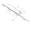
- Figs. 1 and 2 show an embodiment of a bracket 1 according to the invention made of a plate material, e.g. made in an aluminium alloy, the thickness of which is typically 4-5 mm.
- the bracket 1 comprises an oblong body 2 formed of the plate material, one end 4 of the body being slightly tapering and fastening means 3 in the form of a substantially tongue-shaped plate element 7 protruding from the body 2 at a distance from the end point of the end 4, a slit 12 being cut or punched out detaching the plate element on three sides.
- the connection between the plate element 7 and the oblong body 2 is springy at a first side 8, where a bend indicator 17 is typically provided in the form of a groove.
- Two parallel sides, the second 9 and the third side 10, extend from the first side 8, the two sides ending and being connected at a fourth side 11, the fourth side typically comprising retention means 15, e.g. in the form of a saw-toothed edge.
- the mentioned second, third and fourth sides are defined by the slit 12.
- the plate element 7 is thus a partially punched out part of the body 2 and is bent at an angle prior to use so that the surface 13 of the plate element 7 forms an angle of 20-30 degrees, preferably 25 degrees with one surface 14 of the body, the first surface 28.
- the slit 12 extends in a direction opposite the fourth side 11 and beyond the first side 8 indicated by the above-mentioned bend indicator 17.
- the slit 12 thus ends in a first 30 and a second area 31 on opposite sides of the first side 8 and at a distance of 2-4 mm from this.
- the bend indicator 17 ensures that the plate element 7 is not wrenched or bent unevenly, but precisely as indicated by the bend indicator or groove and without cracking the body 2 from which it extends.
- the width of the slit 12 is 1-3 mm, preferably 2 mm.
- the end curvature 16 ends in a first 30 and a second area 31 on their respective side of the first side 8 of the plate element 7. There are thus two end curvatures 16 as the slit 12 is an unbroken slit surrounding the plate element 7.
- a support part 6 is provided for mounting of a holding device 22.
- the support part 6 formed as a protruding part 18, which as mentioned is punched out of the plate material. Subsequently, the protruding part 18 is bent so that an angle of 90-100 degrees is formed between the plane surface of the protruding part and the other plane surface 14 of the body, i.e. the second surface 29.
- the protruding part 18 of the plate is bent so that its surface extends parallel to the longitudinal axis of the body 2, making the design very strong as a force applied to the protruding part will extend parallel to its bend line 19. The force is applied in connection with mounting of the bracket 1 on a roof 25.
- the protruding part 18 itself comprises one, two or possibly several bores 23 for receiving a holding device 22, e.g. in the form of pipes. The longitudinal axis of these pipes thus creates an angle of approximately 90 degrees with the longitudinal axis of the body 2.
- Figs. 3A-C show the bracket 1 being mounted on a roof 25, the springy plate element 7 being bent at the mentioned angle of approximately 25 degrees and the protruding part 18 being bent in the opposite direction of the springy part at an angle of 90-100 degrees.
- One end of the bracket 1 is inserted under a roof tile 26, the subjacent roof tile causing the springy part to be pushed upwards towards the superjacent roof tile, in effect lifting this to facilitate insertion.
- the angle between the body 2 and the plate element 7 is open in a direction opposite the direction of insertion.
- Fig. 3B shows the bracket 1 in its end position, the plate element 7 springing back as soon as it is free of the subjacent roof tile 26.
- the bracket 1 is then drawn in a direction opposite the direction of insertion so that the fourth side 11 of the plate element 7, which as mentioned preferably comprises retention means 15, penetrates the subjacent batten.
- the bracket 1 is thus mounted securely to the roof 25 and the force evenly distributed.
- the bracket 1 is shown providing a snow catcher retaining the snow 27 by means of a holding device 22 in form of the mentioned pipes provided in the bores 23 of the protruding part 18.
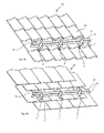
- Figs. 4A and B show a set of brackets 1 mounted on a roof 25, the roof tiles 26 in Fig. 4A differing from the roof tiles 26 in Fig. 4B .
- the bracket 1 is used to provide a snow catcher and it shows that the bracket can be used regardless of the type of roof tiles 26 used as long as transverse battens into which the plate element 7 may engage to fasten the bracket securely are positioned under the roof tiles.
- the brackets 1 are of course mounted in the same row of roof tiles 26 to enable the holding device 22 in the form of pipes to be inserted through the bores 23 in the protruding parts 18 of each bracket.
- the bracket 1 is shown having only one protruding part 18, but might as well have two protruding parts positioned opposite each other, which would typically be the case for brackets mounted in the end areas of the roof 25, i.e. along its right and left edge.
- the brackets 1 are typically mounted by bending the plate element 7 constituting the fastening means 23 to an angle of approximately 25 degrees along the pre-stamped groove or bend indicator 17, which is approximately 15-30 mm long depending on the roof type.
- the bracket 1 is inserted upwards between the roof tiles 26 after which it springs back to its pre-bent position and anchors itself to the batten.
- a holding device 22 in the form of one or two pipes extending though the brackets 1 are mounted and secured by the protruding parts 18 or pipe holders.
- brackets 1 with double pipe holders are mounted along the end edges of the roof 25, whereas brackets with a pipe holder to the right or left are mounted in the middle of the roof so that movement to the side is prevented.
- the pipes are fastened to the bracket 1 by means of machine screws. To correspond with the chosen dimension, 5 mm machine screws are preferably used.
- a snow catcher is provided which is simple in design, light and easy to mount.
- Fig. 5A shows the bracket 1 according to the invention for providing rungs on a roof 25 and Fig. 5B shows the rung of Fig. 5A mounted on a roof.
- Two brackets 1 are positioned at the same horizontal level on a roof 25 and at a distance suitable for a step, i.e. approximately 30-40 cm.
- a holding device 22 in the form of a plate 33 functioning as a rung is fastened.
- the plate 33 is fastened to the protruding parts 18 using holding means 32, in this case in the form of cylindrical protruding parts fitting into the bores 23 of the protruding parts.
- a rung is thus provided, which may be mounted on the roof 25 as shown in Fig. 5B.
- the fourth sides 11 of the plate elements 7 of the brackets 1 penetrate the same batten with their retention means 15.
- the body 2 is thus positioned on the top face of the roof 25 helping to distribute the pressure, while the retention means 15 ensure that the rung does not slide in relation to the sloping roof.
- Fig. 6 shows rungs provided as shown in figs. 5A and 5B, the rungs in the form of plates 33 being placed on the same vertical level, thus constituting a ladder 20.
- the rungs may also be provided by pipes inserted through the bores 23 of the protruding parts 18 and in effect be fastened in a similar manner as pipes used to provide a snow catcher as described above.
- the distance between the rungs is in the region of 20-40 cm depending on the slope of the roof 25 and the distance between the subjacent battens. The greater the load on the brackets 1, the more they will penetrate the subjacent batten.
- the brackets 1 are typically mounted as described above.
- the shape of the holding device 22 is adapted to fit the required function.
- the holding device 22 may e.g. be provided with supporting sections to be fastened both in the bore 23 of the protruding part 18 and to the solar cell in a suitable manner.
Landscapes
- Engineering & Computer Science (AREA)
- Architecture (AREA)
- Structural Engineering (AREA)
- Civil Engineering (AREA)
- Physics & Mathematics (AREA)
- Life Sciences & Earth Sciences (AREA)
- Sustainable Development (AREA)
- Sustainable Energy (AREA)
- Thermal Sciences (AREA)
- Chemical & Material Sciences (AREA)
- Combustion & Propulsion (AREA)
- Mechanical Engineering (AREA)
- General Engineering & Computer Science (AREA)
- Buildings Adapted To Withstand Abnormal External Influences (AREA)
- Roof Covering Using Slabs Or Stiff Sheets (AREA)
Abstract
Description
- The present invention relates to a bracket made of a plate material for mounting on a roof comprising a fastening means in one end of the body for fastening the bracket to a roof part and a support part in an opposite end of the body, the fastening means comprising a plate element, the plate element being an integrated part of the body and connected to the body along a first side of the plate element, the width of the first side being smaller than the width of the body, the plate element further comprising a second side and a third side extending from the first side as well as a fourth side opposite the first side connecting the second side and the third side.
- Solar cells, ladders and snow catchers a typically mounted on roofs using brackets of various designs. The brackets must either be bolted to the roof tiles at the risk of the roof tiles breaking during the mechanical handling or the roof tiles be lifted to enable the brackets to be adequately fastened to the roof.
-
EP1201844 discloses a snow catcher bracket made of a plate material and having an oblong body with a hook in one end of the body engaging with a roof tile and a support part in an opposite end of the oblong body for catching the snow. The disadvantages of the design of the patent in question is that the hook takes up a lot of space during transportation and that a roof tile must be lifted in order for the hook to be inserted under the overlapping roof tile to engage with the upper edge of roof tile below the lifted roof tile. Not only is this a cumbersome procedure, the entire load is also placed on one roof tile when the snow is caught by the support part. In addition, the support part is bent in a continuation of the oblong body so as to form a triangular shape, seen from the side, in order to be sufficiently strong to support the load of the snow. -
JP 2560115 - The object of the present invention is to provide a roof bracket that does not have the disadvantages of the known roof brackets, or presents an alternative to these.
- This object is achieved by a bracket as described above, where a slit is provided between the second, third and fourth side and the body when the surfaces of the body and the plate element are on the same level and parallel so that the three sides are not connected with the body, the slit ending in a first and a second area each having an end curvature, the end curve curvature of the slit having a radius of curvature of more than 0, and where the plate element is adapted to form an angle V with the plane surface of the body when the fastening means abuts the roof part, the angle V opening towards the support part.
- This structure enables the bracket to be mounted on existing roofs without lifting the roof tiles and/or screwing the bracket to the roof tiles, the latter of which may cause leaks. As the plate element of the bracket is bent at a suitable angle V of approximately 20-30 degrees, preferably approximately 25 degrees, in relation to the extension of the body and as the connection between the plate element and the rest of the snow catcher is springy, the part of the body comprising the plate element may be inserted under a roof tile, the element being pushed upwards towards the body until it is substantially on the same level and parallel with the body. When the element has been inserted so far as to be free of the subjacent roof tile, it springs back to its pre-bent position. The bracket is then drawn in a direction opposite the direction of insertion so that the fourth side of the protruding part of the bracket/plate element engages a subjacent batten and penetrates it. The bracket is thus securely fastened and the load is placed on the batten instead of on the more fragile roof tiles.
- By springy is meant that the plate element, when bent at the suitable angle, may be inserted without being substantially plastically deformed so as to be substantially surface parallel with the rest of the body from which it extends and that the spring force is so that the plate element springs back to its pre-bent position when it is free of the roof tile. The spring force K is adapted to avoid plastic deformation. The roof part is preferably a batten.
- As the slit ends in an end curvature of a given radius of curvature, a notch effect is avoided so that the plate element is not wrenched from the bracket when a load is placed on the bracket.
- In an advantageous embodiment of the bracket, the fourth side is provided with retention means.
- It is thus obtained that the plate element is securely anchored to the subjacent batten. The edge of the retention means may be sharp, pointed or saw-toothed, the sharp teeth penetrating the soft wood. Many different designs are conceivable.
- In an advantageous embodiment of the invention, the two end curvatures of the slit ending in a first and a second area respectively on each their side of the first side of the plate element have a radius of curvature of 0.5-3 mm, preferably 0.5-1.5 mm.
- A notch effect is hereby avoided when the plate element is bent at a suitable angle.
- In an advantageous embodiment of the invention, the first side is spaced from the two end curvatures of the slit towards the fourth side, the first side comprising a bend indicator.
- It is thus obtained that the plate element is bent precisely avoiding that it is bent at an insufficient angle or unevenly along the first side.
- In an advantageous embodiment of the invention, the support part is made of the plate material and constitutes an integrated part of the body, the support part comprising at least one protruding part in relation to the longitudinal sides of the body, a bend line being provided between the body and the protruding part and the protruding part comprising a bore for receiving a holding device.
- It is thus obtained that the surface of the support part, facing the body when bent, forms a substantially straight angle with the plane surface of the body. The surface of the support part itself extend parallel along the longitudinal axis of the body, thus making the design very strong even when using a relatively weak plate material, such as aluminium. This is due to the fact that a load placed on the bent part will have a line of attack parallel to the bend line, instead of perpendicular to the bend line as in the above-mentioned prior art solutions. As mentioned, this facilitates the choice of a light material, such as aluminium, making transportation of the snow catchers easier, aluminium moreover being a corrosion-resistant material. However, the protruding part may also be two fins positioned opposite each other. Through the holes in the fins a holding device, such as one or more pipes, is mounted. The pipes extend continuously through all the brackets mounted on the roof, thus providing a snow catcher. The pipes may also provide rungs, given that two brackets are placed on the same horizontal level and at a distance suitable for a rung of a ladder.
- In an advantageous embodiment of the invention, the angle V is acute, preferably 20-30 degrees.
- In an advantageous embodiment of the invention, the support part and the plane surface of the body facing each other form an angle Q, the angle Q preferably being 90-100 degrees, thus facilitating stacking of the brackets during transportation.
- In an advantageous embodiment of the invention, the angle V is positioned between the first surface of the body and the plate element and the angle Q is positioned between the second surface of the body - positioned opposite the first surface - and the support part, the two angles facing in opposite direction.
- In an advantageous embodiment of the invention, the plate material comprises an aluminium alloy.
- In an advantageous embodiment of the invention, the fastening means is tongue-shaped.
- In an advantageous embodiment of the invention, the connection between the plate element and the body is springy and comprises a spring force K.
- In an advantageous embodiment of the invention, the abutment against the roof part comprises abutment between the roof part and the fourth side.
- In an advantageous embodiment of the invention, the support part is adapted to receive a holding device, such as a pipe, a plate or a section.
- The invention also relates to a method for mounting a bracket on a roof, where the bracket is bent along its first side to form an angle V, the support part or parts are bent to form an angle Q opposing the angle V, the body is inserted between an upper and a lower roof tile with the plate element facing the lower roof tile and the bracket, when the plate element is free of the roof tile, is drawn in a direction opposite the direction of insertion so that the fourth side of the plate element engages a subjacent batten
- The invention will be described in more detail below with reference to the drawings, in which:
-
Fig. 1 shows a bracket according to the invention ready to be inserted under a roof plate or tile, -
Fig. 2 shows the bracket ofFig. 1 punched out in a plate material prior to bending the bracket to provide the protruding, springy fastening means and the raised support part, -
Fig. 3A shows the bracket ofFig. 1 inserted under a roof plate or tile, -
Fig. 3B shows the bracket ofFig. 3A in its end position, the springy plate element abutting a batten, -
Fig. 3C shows the bracket ofFig. 3B in relation to a mass of snow lying on the roof, -
Figs. 4A and B show a snow catcher according to the invention mounted on a roof, the roof tiles inFig. 4A differing from the roof tiles inFig. 4B , - Fig. 5A shows a bracket according to the invention for providing a rung on a roof,
- Fig. 5B shows the bracket of Fig. 5A mounted on a roof, and
- Fig. 6 shows a ladder on a roof made by means of a bracket according to the invention.
-
Figs. 1 and2 show an embodiment of abracket 1 according to the invention made of a plate material, e.g. made in an aluminium alloy, the thickness of which is typically 4-5 mm. Thebracket 1 comprises anoblong body 2 formed of the plate material, one end 4 of the body being slightly tapering and fastening means 3 in the form of a substantially tongue-shapedplate element 7 protruding from thebody 2 at a distance from the end point of the end 4, aslit 12 being cut or punched out detaching the plate element on three sides. The connection between theplate element 7 and theoblong body 2 is springy at a first side 8, where abend indicator 17 is typically provided in the form of a groove. Two parallel sides, the second 9 and thethird side 10, extend from the first side 8, the two sides ending and being connected at afourth side 11, the fourth side typically comprising retention means 15, e.g. in the form of a saw-toothed edge. The mentioned second, third and fourth sides are defined by theslit 12. - The
plate element 7 is thus a partially punched out part of thebody 2 and is bent at an angle prior to use so that thesurface 13 of theplate element 7 forms an angle of 20-30 degrees, preferably 25 degrees with onesurface 14 of the body, thefirst surface 28. Theslit 12 extends in a direction opposite thefourth side 11 and beyond the first side 8 indicated by the above-mentionedbend indicator 17. Theslit 12 thus ends in a first 30 and asecond area 31 on opposite sides of the first side 8 and at a distance of 2-4 mm from this. Thebend indicator 17 ensures that theplate element 7 is not wrenched or bent unevenly, but precisely as indicated by the bend indicator or groove and without cracking thebody 2 from which it extends. This is obtained by the extension of theslit 12 and by the slit ending in anend curvature 16 with a radius of curvature of more than 0 and typically 0.5-3 mm, preferably 0.5-1.5 mm. The width of theslit 12 is 1-3 mm, preferably 2 mm. - The
end curvature 16 ends in a first 30 and asecond area 31 on their respective side of the first side 8 of theplate element 7. There are thus twoend curvatures 16 as theslit 12 is an unbroken slit surrounding theplate element 7. - Opposite the
plate element 7 in theother end 24 of thebody 2, asupport part 6 is provided for mounting of a holdingdevice 22. Thesupport part 6 formed as a protrudingpart 18, which as mentioned is punched out of the plate material. Subsequently, the protrudingpart 18 is bent so that an angle of 90-100 degrees is formed between the plane surface of the protruding part and theother plane surface 14 of the body, i.e. the second surface 29. The protrudingpart 18 of the plate is bent so that its surface extends parallel to the longitudinal axis of thebody 2, making the design very strong as a force applied to the protruding part will extend parallel to itsbend line 19. The force is applied in connection with mounting of thebracket 1 on aroof 25. The protrudingpart 18 itself comprises one, two or possiblyseveral bores 23 for receiving a holdingdevice 22, e.g. in the form of pipes. The longitudinal axis of these pipes thus creates an angle of approximately 90 degrees with the longitudinal axis of thebody 2. -
Figs. 3A-C show thebracket 1 being mounted on aroof 25, thespringy plate element 7 being bent at the mentioned angle of approximately 25 degrees and the protrudingpart 18 being bent in the opposite direction of the springy part at an angle of 90-100 degrees. One end of thebracket 1 is inserted under aroof tile 26, the subjacent roof tile causing the springy part to be pushed upwards towards the superjacent roof tile, in effect lifting this to facilitate insertion. The angle between thebody 2 and theplate element 7 is open in a direction opposite the direction of insertion. -
Fig. 3B shows thebracket 1 in its end position, theplate element 7 springing back as soon as it is free of thesubjacent roof tile 26. Thebracket 1 is then drawn in a direction opposite the direction of insertion so that thefourth side 11 of theplate element 7, which as mentioned preferably comprises retention means 15, penetrates the subjacent batten. Thebracket 1 is thus mounted securely to theroof 25 and the force evenly distributed. - In
Fig. 3C , thebracket 1 is shown providing a snow catcher retaining thesnow 27 by means of a holdingdevice 22 in form of the mentioned pipes provided in thebores 23 of the protrudingpart 18. -
Figs. 4A and B show a set ofbrackets 1 mounted on aroof 25, theroof tiles 26 inFig. 4A differing from theroof tiles 26 inFig. 4B . In this case, thebracket 1 is used to provide a snow catcher and it shows that the bracket can be used regardless of the type ofroof tiles 26 used as long as transverse battens into which theplate element 7 may engage to fasten the bracket securely are positioned under the roof tiles. Thebrackets 1 are of course mounted in the same row ofroof tiles 26 to enable the holdingdevice 22 in the form of pipes to be inserted through thebores 23 in the protrudingparts 18 of each bracket. Thebracket 1 is shown having only one protrudingpart 18, but might as well have two protruding parts positioned opposite each other, which would typically be the case for brackets mounted in the end areas of theroof 25, i.e. along its right and left edge. - The
brackets 1 are typically mounted by bending theplate element 7 constituting the fastening means 23 to an angle of approximately 25 degrees along the pre-stamped groove orbend indicator 17, which is approximately 15-30 mm long depending on the roof type. Thebracket 1 is inserted upwards between theroof tiles 26 after which it springs back to its pre-bent position and anchors itself to the batten. Subsequently, a holdingdevice 22 in the form of one or two pipes extending though thebrackets 1 are mounted and secured by the protrudingparts 18 or pipe holders. As mentioned,brackets 1 with double pipe holders are mounted along the end edges of theroof 25, whereas brackets with a pipe holder to the right or left are mounted in the middle of the roof so that movement to the side is prevented. The pipes are fastened to thebracket 1 by means of machine screws. To correspond with the chosen dimension, 5 mm machine screws are preferably used. Thus, a snow catcher is provided which is simple in design, light and easy to mount. - Fig. 5A shows the
bracket 1 according to the invention for providing rungs on aroof 25 and Fig. 5B shows the rung of Fig. 5A mounted on a roof. Twobrackets 1 are positioned at the same horizontal level on aroof 25 and at a distance suitable for a step, i.e. approximately 30-40 cm. Through the twobores 23 of two the bent protruding parts 18 a holdingdevice 22 in the form of a plate 33 functioning as a rung is fastened. The plate 33 is fastened to the protrudingparts 18 using holding means 32, in this case in the form of cylindrical protruding parts fitting into thebores 23 of the protruding parts. A rung is thus provided, which may be mounted on theroof 25 as shown in Fig. 5B. The fourth sides 11 of theplate elements 7 of thebrackets 1 penetrate the same batten with their retention means 15. Thebody 2 is thus positioned on the top face of theroof 25 helping to distribute the pressure, while the retention means 15 ensure that the rung does not slide in relation to the sloping roof. - Fig. 6 shows rungs provided as shown in figs. 5A and 5B, the rungs in the form of plates 33 being placed on the same vertical level, thus constituting a ladder 20. However, the rungs may also be provided by pipes inserted through the
bores 23 of the protrudingparts 18 and in effect be fastened in a similar manner as pipes used to provide a snow catcher as described above. The distance between the rungs is in the region of 20-40 cm depending on the slope of theroof 25 and the distance between the subjacent battens. The greater the load on thebrackets 1, the more they will penetrate the subjacent batten. - The
brackets 1 are typically mounted as described above. The shape of the holdingdevice 22 is adapted to fit the required function. In case abracket 1 is to be used for mounting a solar cell, the holdingdevice 22 may e.g. be provided with supporting sections to be fastened both in thebore 23 of the protrudingpart 18 and to the solar cell in a suitable manner. -
- 1.
- bracket
- 2.
- body
- 3.
- fastening means
- 4.
- one end of the body
- 5.
- roof part
- 6.
- support part
- 7.
- plate element
- 8.
- first side
- 9.
- second side
- 10.
- third side
- 11.
- fourth side
- 12.
- slit
- 13.
- plane surface of the plate element
- 14.
- plane surface of the body
- 15.
- retention means
- 16.
- end curvature
- 17.
- bend indicator
- 18.
- protruding part
- 19.
- bend line
- 20.
- ladder
- 21.
- -
- 22.
- holding device2
- 3.
- bore
- 24.
- other end of the body
- 25.
- roof
- 26.
- roof tile
- 27.
- snow
- 28.
- first surface
- 29.
- second surface
- 30.
- first area
- 31.
- second area
- 32.
- holding means
- 33.
- plate (rung)
Claims (14)
- Bracket (1) made of a plate material for mounting on a roof comprising a body (2) with a fastening means (3) in one end of the body (2) for fastening the bracket (1) to a roof part (5) and a support part (6) in an opposite end of the body (2), the fastening means (3) comprising a plate element (7), the plate element (7) being an integrated part of the body (2) and connected to the body (2) along a first side (8) of the plate element (7), the width of the first side (8) being smaller than the width of the body (2), the plate element (7) further comprising a second side (9) and a third side (10) extending from the first side (8) as well as a fourth side (11) opposite the first side (8) connecting the second side (9) and the third side (10), characterised in that a slit (12) is provided between the second, third and fourth side and the body when the surfaces of the body (2) and the plate element (7) are on the same level and parallel so that the three sides are not connected with the body (2), the slit (12) ending in a first (30) and a second area (31) each having an end curvature (16), the end curvature (12) of the slit having a radius of curvature of more than 0, and that the plate element (7) is adapted to form an angle V with the plane surface (14) of the body when the fastening means (3) abuts the roof part (5), the angle V opening towards the support part (6).
- Bracket (1) according to claim 1 wherein the fourth side (11) is provided with retention means (15).
- Bracket (1) according to claim 1 or 2 wherein the two end curvatures (16) of the slit (12) ending in a first (30) and a second area (31) respectively on each their side of the first side (8) of the plate element (7) have a of curvature of radius of 0,5-3 mm, preferably 0,5-1,5 mm.
- Bracket (1) according to any of the preceding claims wherein the first side (8) is spaced from the two end curvatures (16) of the slit (12) towards the fourth side (11), the first side (8) comprising a bend indicator (17).
- Bracket (1) according to any of the preceding claims wherein the support part (6) is formed of the plate material and constitutes an integrated part of the body (2), the support part (6) comprising at least one protruding part (18) in relation to the longitudinal sides of the body, a bend line (19) being provided between the body (2) and the protruding part (18) and the protruding part (18) comprising a bore (22) for receiving a holding device (22).
- Bracket (1) according to claim 5 wherein the holding device (22) comprises a snow catching means, preferably at least one rod extending transversely to the longitudinal axis of the body and being mounted in the bores (23) of the support part (6).
- Bracket (1) according to claim 5 wherein the holding device (22) provides a rung comprising holding means adapted to be received in the bores of the support part.
- Bracket (1) according to any of the preceding claims wherein the angle V is acute, preferably 20-30 degrees.
- Bracket (1) according to any of the preceding claims wherein the surface of the support part (6) and the plate body facing each other form an angle Q, the angle Q preferably being 90-100 degrees.
- Bracket (1) according to any of the preceding claims wherein the angle V is positioned between the first surface (28) of the body and the plate element (7) and the angle Q is positioned between the second surface (29) of the body - positioned opposite the first surface (28) - and the support part (6), the two angles facing in opposite direction.
- Bracket (1) according to any of the preceding claims wherein the connection between the plate element (7) and the body (2) is springy and comprises a spring force K.
- Bracket (1) according to any of the preceding claims wherein the abutment against the roof part (5) comprises abutment between the roof part (5) and the fourth side (11).
- Bracket (1) according to any of the preceding claims wherein the support part (6) is adapted to receive a holding device (22), such as a pipe, a plate or a section.
- Method for mounting a bracket (1) according to any of the preceding claims on a roof characterised in that the plate element (7) of the bracket (1) is bent along its first side (8) to form an angle V, that the support part or parts (6) are bent to form an angle Q opposing the angle V, that the body (2) is inserted between an upper and a lower roof tile (26) with the plate element (7) facing the lower roof tile (26) and that the bracket (1), when the plate element (7) is free of the roof tile (26), is drawn in a direction opposite the direction of insertion so that the fourth side (11) of the plate element engages a subjacent batten.
Applications Claiming Priority (1)
| Application Number | Priority Date | Filing Date | Title |
|---|---|---|---|
| DKPA201170262A DK177405B1 (en) | 2011-05-27 | 2011-05-27 | Snow catcher |
Publications (3)
| Publication Number | Publication Date |
|---|---|
| EP2581520A2 true EP2581520A2 (en) | 2013-04-17 |
| EP2581520A3 EP2581520A3 (en) | 2015-07-22 |
| EP2581520B1 EP2581520B1 (en) | 2019-07-24 |
Family
ID=46210096
Family Applications (1)
| Application Number | Title | Priority Date | Filing Date |
|---|---|---|---|
| EP12169438.4A Active EP2581520B1 (en) | 2011-05-27 | 2012-05-25 | Bracket |
Country Status (2)
| Country | Link |
|---|---|
| EP (1) | EP2581520B1 (en) |
| DK (1) | DK177405B1 (en) |
Cited By (3)
| Publication number | Priority date | Publication date | Assignee | Title |
|---|---|---|---|---|
| SE2051196A1 (en) * | 2020-10-15 | 2022-04-16 | Cwl Patent Ab | Attachment device |
| SE2051228A1 (en) * | 2020-10-21 | 2022-04-22 | Cwl Patent Ab | Roof console |
| EP4174246A1 (en) * | 2021-10-28 | 2023-05-03 | CWL Patent AB | An attachment arrangement for the attachment of one or more roof equipment devices |
Families Citing this family (1)
| Publication number | Priority date | Publication date | Assignee | Title |
|---|---|---|---|---|
| CA3016419A1 (en) | 2015-12-29 | 2017-07-06 | John Holt | Apparatus and methods for secure, non-invasive and non-permanent surface attachment systems |
Citations (2)
| Publication number | Priority date | Publication date | Assignee | Title |
|---|---|---|---|---|
| JP2560115B2 (en) | 1989-06-30 | 1996-12-04 | パラマウントベッド 株式会社 | Cleaning equipment for mattresses and futons |
| EP1201844A2 (en) | 2000-10-25 | 2002-05-02 | Lafarge Roof System Components GmbH & Co. KG | Snow trap hook |
Family Cites Families (14)
| Publication number | Priority date | Publication date | Assignee | Title |
|---|---|---|---|---|
| US591594A (en) * | 1897-10-12 | Snow-guard | ||
| CH523400A (en) * | 1971-02-04 | 1972-05-31 | Guigoz Andre | Snow hook |
| AT376472B (en) * | 1982-03-03 | 1984-11-26 | Haemmerle Siegfried | SNOW CONTROL DEVICE |
| AT382413B (en) * | 1985-04-01 | 1987-02-25 | Dachan Anstalt | Snow trap |
| JP2505188Y2 (en) * | 1990-03-05 | 1996-07-24 | 積水化学工業株式会社 | Snow stopper |
| JPH076284Y2 (en) * | 1990-08-10 | 1995-02-15 | 株式会社野島角清製作所 | Snow stopper |
| JP2560115Y2 (en) * | 1991-02-07 | 1998-01-21 | ニイガタ製販株式会社 | Snow stopper for colonial roof |
| JP2507302Y2 (en) * | 1993-02-03 | 1996-08-14 | 株式会社原田商店 | Roof snow stopper |
| JP2540153Y2 (en) * | 1993-06-11 | 1997-07-02 | 株式会社野島角清製作所 | Snow stopper |
| US5669184A (en) * | 1996-07-19 | 1997-09-23 | Anderson; Terry Elmer | Snow bracket |
| SE530335C2 (en) * | 2005-05-17 | 2008-05-06 | Cw Lundberg Ind Ab | Bracket for roof equipment |
| GB0722714D0 (en) * | 2007-11-20 | 2007-12-27 | Solar Century Holdings Ltd | Tile support bracket |
| US20090205262A1 (en) * | 2008-02-18 | 2009-08-20 | Andrew Douglas G | Snow-retaining roof bracket |
| DE202011003239U1 (en) * | 2011-02-26 | 2011-05-05 | Otto Lehmann Gmbh | Snow and / or icing device |
-
2011
- 2011-05-27 DK DKPA201170262A patent/DK177405B1/en not_active IP Right Cessation
-
2012
- 2012-05-25 EP EP12169438.4A patent/EP2581520B1/en active Active
Patent Citations (2)
| Publication number | Priority date | Publication date | Assignee | Title |
|---|---|---|---|---|
| JP2560115B2 (en) | 1989-06-30 | 1996-12-04 | パラマウントベッド 株式会社 | Cleaning equipment for mattresses and futons |
| EP1201844A2 (en) | 2000-10-25 | 2002-05-02 | Lafarge Roof System Components GmbH & Co. KG | Snow trap hook |
Cited By (4)
| Publication number | Priority date | Publication date | Assignee | Title |
|---|---|---|---|---|
| SE2051196A1 (en) * | 2020-10-15 | 2022-04-16 | Cwl Patent Ab | Attachment device |
| SE2051228A1 (en) * | 2020-10-21 | 2022-04-22 | Cwl Patent Ab | Roof console |
| SE545488C2 (en) * | 2020-10-21 | 2023-09-26 | Cwl Patent Ab | Roof console with deformation structures comprising cutouts and attachment arrangement with a roof console and an attachment element |
| EP4174246A1 (en) * | 2021-10-28 | 2023-05-03 | CWL Patent AB | An attachment arrangement for the attachment of one or more roof equipment devices |
Also Published As
| Publication number | Publication date |
|---|---|
| DK177405B1 (en) | 2013-04-02 |
| EP2581520A3 (en) | 2015-07-22 |
| DK201170262A (en) | 2012-11-28 |
| EP2581520B1 (en) | 2019-07-24 |
Similar Documents
| Publication | Publication Date | Title |
|---|---|---|
| US10508833B2 (en) | Integrated hook and flashing for photovoltaic module installation on tile roofs | |
| EP2581520B1 (en) | Bracket | |
| US8936224B2 (en) | Mounting system, especially for solar modules | |
| US7707785B2 (en) | Variable girder tie | |
| US9608559B2 (en) | Slide fit mounting clip for installing photovoltaic modules | |
| EP3361183A1 (en) | Stabilisation element and method for stabilizing a roof hook with respect to a roof tile | |
| US20210348633A1 (en) | Pin | |
| US8661760B2 (en) | Wind resistant tile roofing system | |
| US7386961B2 (en) | Bracket, method of making, and method of mounting rooftop elements on rooftop structure | |
| EP2455683A2 (en) | Fixing of panel-shaped elements | |
| CA2621888C (en) | Snow-retaining roof bracket | |
| EP2330256A2 (en) | Roof tile with a variable fixing element for roof attachments | |
| EP4060894A1 (en) | Ballast tank | |
| KR200470370Y1 (en) | Stiffening member for gutter hanger | |
| DK177563B1 (en) | Brackets and method of mounting the bracket | |
| JP6045021B2 (en) | Attaching tool for installation on the roof and method of attaching the installation on the roof using the attachment | |
| JP5648995B2 (en) | Mounting structure of support frame and exterior structure | |
| JP6814543B2 (en) | Mounting bracket for roof-standing equipment | |
| CN215594632U (en) | Self-locking clamp for color steel tile | |
| JP7012956B2 (en) | Noshi tile fixing method and Noshi tile fixing tool | |
| RU69896U1 (en) | MAIN CEILING PROFILE | |
| AU2021201751A1 (en) | Pin | |
| AU2014202141B2 (en) | External Gutter System | |
| CN113502984A (en) | Self-locking clamp for color steel tile and working method thereof | |
| AU2012100148A4 (en) | Mounting assembly |
Legal Events
| Date | Code | Title | Description |
|---|---|---|---|
| PUAI | Public reference made under article 153(3) epc to a published international application that has entered the european phase |
Free format text: ORIGINAL CODE: 0009012 |
|
| AK | Designated contracting states |
Kind code of ref document: A2 Designated state(s): AL AT BE BG CH CY CZ DE DK EE ES FI FR GB GR HR HU IE IS IT LI LT LU LV MC MK MT NL NO PL PT RO RS SE SI SK SM TR |
|
| AX | Request for extension of the european patent |
Extension state: BA ME |
|
| PUAL | Search report despatched |
Free format text: ORIGINAL CODE: 0009013 |
|
| AK | Designated contracting states |
Kind code of ref document: A3 Designated state(s): AL AT BE BG CH CY CZ DE DK EE ES FI FR GB GR HR HU IE IS IT LI LT LU LV MC MK MT NL NO PL PT RO RS SE SI SK SM TR |
|
| AX | Request for extension of the european patent |
Extension state: BA ME |
|
| RIC1 | Information provided on ipc code assigned before grant |
Ipc: F24J 2/52 20060101ALI20150612BHEP Ipc: E04D 13/10 20060101AFI20150612BHEP Ipc: E06C 1/34 20060101ALI20150612BHEP |
|
| 17P | Request for examination filed |
Effective date: 20160122 |
|
| RBV | Designated contracting states (corrected) |
Designated state(s): AL AT BE BG CH CY CZ DE DK EE ES FI FR GB GR HR HU IE IS IT LI LT LU LV MC MK MT NL NO PL PT RO RS SE SI SK SM TR |
|
| STAA | Information on the status of an ep patent application or granted ep patent |
Free format text: STATUS: EXAMINATION IS IN PROGRESS |
|
| 17Q | First examination report despatched |
Effective date: 20161121 |
|
| GRAP | Despatch of communication of intention to grant a patent |
Free format text: ORIGINAL CODE: EPIDOSNIGR1 |
|
| STAA | Information on the status of an ep patent application or granted ep patent |
Free format text: STATUS: GRANT OF PATENT IS INTENDED |
|
| RIC1 | Information provided on ipc code assigned before grant |
Ipc: E04D 13/10 20060101AFI20190117BHEP Ipc: E06C 1/34 20060101ALI20190117BHEP Ipc: F24S 25/613 20180101ALI20190117BHEP |
|
| INTG | Intention to grant announced |
Effective date: 20190204 |
|
| GRAS | Grant fee paid |
Free format text: ORIGINAL CODE: EPIDOSNIGR3 |
|
| GRAA | (expected) grant |
Free format text: ORIGINAL CODE: 0009210 |
|
| STAA | Information on the status of an ep patent application or granted ep patent |
Free format text: STATUS: THE PATENT HAS BEEN GRANTED |
|
| AK | Designated contracting states |
Kind code of ref document: B1 Designated state(s): AL AT BE BG CH CY CZ DE DK EE ES FI FR GB GR HR HU IE IS IT LI LT LU LV MC MK MT NL NO PL PT RO RS SE SI SK SM TR |
|
| REG | Reference to a national code |
Ref country code: GB Ref legal event code: FG4D |
|
| REG | Reference to a national code |
Ref country code: CH Ref legal event code: EP |
|
| REG | Reference to a national code |
Ref country code: DE Ref legal event code: R096 Ref document number: 602012062196 Country of ref document: DE |
|
| REG | Reference to a national code |
Ref country code: AT Ref legal event code: REF Ref document number: 1158364 Country of ref document: AT Kind code of ref document: T Effective date: 20190815 |
|
| REG | Reference to a national code |
Ref country code: IE Ref legal event code: FG4D |
|
| REG | Reference to a national code |
Ref country code: SE Ref legal event code: TRGR |
|
| REG | Reference to a national code |
Ref country code: NL Ref legal event code: MP Effective date: 20190724 |
|
| REG | Reference to a national code |
Ref country code: LT Ref legal event code: MG4D |
|
| REG | Reference to a national code |
Ref country code: NO Ref legal event code: T2 Effective date: 20190724 |
|
| REG | Reference to a national code |
Ref country code: AT Ref legal event code: MK05 Ref document number: 1158364 Country of ref document: AT Kind code of ref document: T Effective date: 20190724 |
|
| PG25 | Lapsed in a contracting state [announced via postgrant information from national office to epo] |
Ref country code: AT Free format text: LAPSE BECAUSE OF FAILURE TO SUBMIT A TRANSLATION OF THE DESCRIPTION OR TO PAY THE FEE WITHIN THE PRESCRIBED TIME-LIMIT Effective date: 20190724 Ref country code: FI Free format text: LAPSE BECAUSE OF FAILURE TO SUBMIT A TRANSLATION OF THE DESCRIPTION OR TO PAY THE FEE WITHIN THE PRESCRIBED TIME-LIMIT Effective date: 20190724 Ref country code: HR Free format text: LAPSE BECAUSE OF FAILURE TO SUBMIT A TRANSLATION OF THE DESCRIPTION OR TO PAY THE FEE WITHIN THE PRESCRIBED TIME-LIMIT Effective date: 20190724 Ref country code: NL Free format text: LAPSE BECAUSE OF FAILURE TO SUBMIT A TRANSLATION OF THE DESCRIPTION OR TO PAY THE FEE WITHIN THE PRESCRIBED TIME-LIMIT Effective date: 20190724 Ref country code: LT Free format text: LAPSE BECAUSE OF FAILURE TO SUBMIT A TRANSLATION OF THE DESCRIPTION OR TO PAY THE FEE WITHIN THE PRESCRIBED TIME-LIMIT Effective date: 20190724 Ref country code: BG Free format text: LAPSE BECAUSE OF FAILURE TO SUBMIT A TRANSLATION OF THE DESCRIPTION OR TO PAY THE FEE WITHIN THE PRESCRIBED TIME-LIMIT Effective date: 20191024 Ref country code: PT Free format text: LAPSE BECAUSE OF FAILURE TO SUBMIT A TRANSLATION OF THE DESCRIPTION OR TO PAY THE FEE WITHIN THE PRESCRIBED TIME-LIMIT Effective date: 20191125 |
|
| PG25 | Lapsed in a contracting state [announced via postgrant information from national office to epo] |
Ref country code: AL Free format text: LAPSE BECAUSE OF FAILURE TO SUBMIT A TRANSLATION OF THE DESCRIPTION OR TO PAY THE FEE WITHIN THE PRESCRIBED TIME-LIMIT Effective date: 20190724 Ref country code: GR Free format text: LAPSE BECAUSE OF FAILURE TO SUBMIT A TRANSLATION OF THE DESCRIPTION OR TO PAY THE FEE WITHIN THE PRESCRIBED TIME-LIMIT Effective date: 20191025 Ref country code: ES Free format text: LAPSE BECAUSE OF FAILURE TO SUBMIT A TRANSLATION OF THE DESCRIPTION OR TO PAY THE FEE WITHIN THE PRESCRIBED TIME-LIMIT Effective date: 20190724 Ref country code: LV Free format text: LAPSE BECAUSE OF FAILURE TO SUBMIT A TRANSLATION OF THE DESCRIPTION OR TO PAY THE FEE WITHIN THE PRESCRIBED TIME-LIMIT Effective date: 20190724 Ref country code: RS Free format text: LAPSE BECAUSE OF FAILURE TO SUBMIT A TRANSLATION OF THE DESCRIPTION OR TO PAY THE FEE WITHIN THE PRESCRIBED TIME-LIMIT Effective date: 20190724 Ref country code: IS Free format text: LAPSE BECAUSE OF FAILURE TO SUBMIT A TRANSLATION OF THE DESCRIPTION OR TO PAY THE FEE WITHIN THE PRESCRIBED TIME-LIMIT Effective date: 20191124 |
|
| PG25 | Lapsed in a contracting state [announced via postgrant information from national office to epo] |
Ref country code: TR Free format text: LAPSE BECAUSE OF FAILURE TO SUBMIT A TRANSLATION OF THE DESCRIPTION OR TO PAY THE FEE WITHIN THE PRESCRIBED TIME-LIMIT Effective date: 20190724 |
|
| PG25 | Lapsed in a contracting state [announced via postgrant information from national office to epo] |
Ref country code: RO Free format text: LAPSE BECAUSE OF FAILURE TO SUBMIT A TRANSLATION OF THE DESCRIPTION OR TO PAY THE FEE WITHIN THE PRESCRIBED TIME-LIMIT Effective date: 20190724 Ref country code: PL Free format text: LAPSE BECAUSE OF FAILURE TO SUBMIT A TRANSLATION OF THE DESCRIPTION OR TO PAY THE FEE WITHIN THE PRESCRIBED TIME-LIMIT Effective date: 20190724 Ref country code: EE Free format text: LAPSE BECAUSE OF FAILURE TO SUBMIT A TRANSLATION OF THE DESCRIPTION OR TO PAY THE FEE WITHIN THE PRESCRIBED TIME-LIMIT Effective date: 20190724 Ref country code: DK Free format text: LAPSE BECAUSE OF FAILURE TO SUBMIT A TRANSLATION OF THE DESCRIPTION OR TO PAY THE FEE WITHIN THE PRESCRIBED TIME-LIMIT Effective date: 20190724 Ref country code: IT Free format text: LAPSE BECAUSE OF FAILURE TO SUBMIT A TRANSLATION OF THE DESCRIPTION OR TO PAY THE FEE WITHIN THE PRESCRIBED TIME-LIMIT Effective date: 20190724 |
|
| PG25 | Lapsed in a contracting state [announced via postgrant information from national office to epo] |
Ref country code: CZ Free format text: LAPSE BECAUSE OF FAILURE TO SUBMIT A TRANSLATION OF THE DESCRIPTION OR TO PAY THE FEE WITHIN THE PRESCRIBED TIME-LIMIT Effective date: 20190724 Ref country code: SM Free format text: LAPSE BECAUSE OF FAILURE TO SUBMIT A TRANSLATION OF THE DESCRIPTION OR TO PAY THE FEE WITHIN THE PRESCRIBED TIME-LIMIT Effective date: 20190724 Ref country code: IS Free format text: LAPSE BECAUSE OF FAILURE TO SUBMIT A TRANSLATION OF THE DESCRIPTION OR TO PAY THE FEE WITHIN THE PRESCRIBED TIME-LIMIT Effective date: 20200224 Ref country code: SK Free format text: LAPSE BECAUSE OF FAILURE TO SUBMIT A TRANSLATION OF THE DESCRIPTION OR TO PAY THE FEE WITHIN THE PRESCRIBED TIME-LIMIT Effective date: 20190724 |
|
| REG | Reference to a national code |
Ref country code: DE Ref legal event code: R097 Ref document number: 602012062196 Country of ref document: DE |
|
| PLBE | No opposition filed within time limit |
Free format text: ORIGINAL CODE: 0009261 |
|
| STAA | Information on the status of an ep patent application or granted ep patent |
Free format text: STATUS: NO OPPOSITION FILED WITHIN TIME LIMIT |
|
| PG2D | Information on lapse in contracting state deleted |
Ref country code: IS |
|
| 26N | No opposition filed |
Effective date: 20200603 |
|
| PG25 | Lapsed in a contracting state [announced via postgrant information from national office to epo] |
Ref country code: SI Free format text: LAPSE BECAUSE OF FAILURE TO SUBMIT A TRANSLATION OF THE DESCRIPTION OR TO PAY THE FEE WITHIN THE PRESCRIBED TIME-LIMIT Effective date: 20190724 |
|
| PG25 | Lapsed in a contracting state [announced via postgrant information from national office to epo] |
Ref country code: MC Free format text: LAPSE BECAUSE OF FAILURE TO SUBMIT A TRANSLATION OF THE DESCRIPTION OR TO PAY THE FEE WITHIN THE PRESCRIBED TIME-LIMIT Effective date: 20190724 Ref country code: CH Free format text: LAPSE BECAUSE OF NON-PAYMENT OF DUE FEES Effective date: 20200531 Ref country code: LI Free format text: LAPSE BECAUSE OF NON-PAYMENT OF DUE FEES Effective date: 20200531 |
|
| REG | Reference to a national code |
Ref country code: BE Ref legal event code: MM Effective date: 20200531 |
|
| GBPC | Gb: european patent ceased through non-payment of renewal fee |
Effective date: 20200525 |
|
| PG25 | Lapsed in a contracting state [announced via postgrant information from national office to epo] |
Ref country code: LU Free format text: LAPSE BECAUSE OF NON-PAYMENT OF DUE FEES Effective date: 20200525 |
|
| PG25 | Lapsed in a contracting state [announced via postgrant information from national office to epo] |
Ref country code: FR Free format text: LAPSE BECAUSE OF NON-PAYMENT OF DUE FEES Effective date: 20200531 Ref country code: GB Free format text: LAPSE BECAUSE OF NON-PAYMENT OF DUE FEES Effective date: 20200525 Ref country code: IE Free format text: LAPSE BECAUSE OF NON-PAYMENT OF DUE FEES Effective date: 20200525 |
|
| PG25 | Lapsed in a contracting state [announced via postgrant information from national office to epo] |
Ref country code: BE Free format text: LAPSE BECAUSE OF NON-PAYMENT OF DUE FEES Effective date: 20200531 |
|
| PGFP | Annual fee paid to national office [announced via postgrant information from national office to epo] |
Ref country code: DE Payment date: 20210520 Year of fee payment: 10 Ref country code: NO Payment date: 20210521 Year of fee payment: 10 |
|
| PGFP | Annual fee paid to national office [announced via postgrant information from national office to epo] |
Ref country code: SE Payment date: 20210520 Year of fee payment: 10 |
|
| PG25 | Lapsed in a contracting state [announced via postgrant information from national office to epo] |
Ref country code: MT Free format text: LAPSE BECAUSE OF FAILURE TO SUBMIT A TRANSLATION OF THE DESCRIPTION OR TO PAY THE FEE WITHIN THE PRESCRIBED TIME-LIMIT Effective date: 20190724 Ref country code: CY Free format text: LAPSE BECAUSE OF FAILURE TO SUBMIT A TRANSLATION OF THE DESCRIPTION OR TO PAY THE FEE WITHIN THE PRESCRIBED TIME-LIMIT Effective date: 20190724 |
|
| PG25 | Lapsed in a contracting state [announced via postgrant information from national office to epo] |
Ref country code: MK Free format text: LAPSE BECAUSE OF FAILURE TO SUBMIT A TRANSLATION OF THE DESCRIPTION OR TO PAY THE FEE WITHIN THE PRESCRIBED TIME-LIMIT Effective date: 20190724 |
|
| REG | Reference to a national code |
Ref country code: DE Ref legal event code: R119 Ref document number: 602012062196 Country of ref document: DE |
|
| REG | Reference to a national code |
Ref country code: NO Ref legal event code: MMEP |
|
| REG | Reference to a national code |
Ref country code: SE Ref legal event code: EUG |
|
| PG25 | Lapsed in a contracting state [announced via postgrant information from national office to epo] |
Ref country code: SE Free format text: LAPSE BECAUSE OF NON-PAYMENT OF DUE FEES Effective date: 20220526 Ref country code: NO Free format text: LAPSE BECAUSE OF NON-PAYMENT OF DUE FEES Effective date: 20220531 |
|
| PG25 | Lapsed in a contracting state [announced via postgrant information from national office to epo] |
Ref country code: DE Free format text: LAPSE BECAUSE OF NON-PAYMENT OF DUE FEES Effective date: 20221201 |