JP6814543B2 - Mounting bracket for roof-standing equipment - Google Patents
Mounting bracket for roof-standing equipment Download PDFInfo
- Publication number
- JP6814543B2 JP6814543B2 JP2016027677A JP2016027677A JP6814543B2 JP 6814543 B2 JP6814543 B2 JP 6814543B2 JP 2016027677 A JP2016027677 A JP 2016027677A JP 2016027677 A JP2016027677 A JP 2016027677A JP 6814543 B2 JP6814543 B2 JP 6814543B2
- Authority
- JP
- Japan
- Prior art keywords
- roof
- support member
- mounting bracket
- receiving portion
- bolt
- Prior art date
- Legal status (The legal status is an assumption and is not a legal conclusion. Google has not performed a legal analysis and makes no representation as to the accuracy of the status listed.)
- Active
Links
- 230000000149 penetrating effect Effects 0.000 claims description 6
- 241000190687 Gobius Species 0.000 claims 1
- XLYOFNOQVPJJNP-UHFFFAOYSA-N water Substances O XLYOFNOQVPJJNP-UHFFFAOYSA-N 0.000 description 15
- 239000002184 metal Substances 0.000 description 9
- 230000000630 rising effect Effects 0.000 description 4
- 238000003780 insertion Methods 0.000 description 3
- 230000037431 insertion Effects 0.000 description 3
- 238000009434 installation Methods 0.000 description 2
- 229910000831 Steel Inorganic materials 0.000 description 1
- 230000006978 adaptation Effects 0.000 description 1
- 238000005452 bending Methods 0.000 description 1
- 238000009957 hemming Methods 0.000 description 1
- 239000000463 material Substances 0.000 description 1
- 238000012986 modification Methods 0.000 description 1
- 230000004048 modification Effects 0.000 description 1
- 238000004826 seaming Methods 0.000 description 1
- 239000007787 solid Substances 0.000 description 1
- 239000010959 steel Substances 0.000 description 1
Images


Classifications
-
- Y—GENERAL TAGGING OF NEW TECHNOLOGICAL DEVELOPMENTS; GENERAL TAGGING OF CROSS-SECTIONAL TECHNOLOGIES SPANNING OVER SEVERAL SECTIONS OF THE IPC; TECHNICAL SUBJECTS COVERED BY FORMER USPC CROSS-REFERENCE ART COLLECTIONS [XRACs] AND DIGESTS
- Y02—TECHNOLOGIES OR APPLICATIONS FOR MITIGATION OR ADAPTATION AGAINST CLIMATE CHANGE
- Y02B—CLIMATE CHANGE MITIGATION TECHNOLOGIES RELATED TO BUILDINGS, e.g. HOUSING, HOUSE APPLIANCES OR RELATED END-USER APPLICATIONS
- Y02B10/00—Integration of renewable energy sources in buildings
- Y02B10/10—Photovoltaic [PV]
-
- Y—GENERAL TAGGING OF NEW TECHNOLOGICAL DEVELOPMENTS; GENERAL TAGGING OF CROSS-SECTIONAL TECHNOLOGIES SPANNING OVER SEVERAL SECTIONS OF THE IPC; TECHNICAL SUBJECTS COVERED BY FORMER USPC CROSS-REFERENCE ART COLLECTIONS [XRACs] AND DIGESTS
- Y02—TECHNOLOGIES OR APPLICATIONS FOR MITIGATION OR ADAPTATION AGAINST CLIMATE CHANGE
- Y02E—REDUCTION OF GREENHOUSE GAS [GHG] EMISSIONS, RELATED TO ENERGY GENERATION, TRANSMISSION OR DISTRIBUTION
- Y02E10/00—Energy generation through renewable energy sources
- Y02E10/50—Photovoltaic [PV] energy
Description
本発明は、はぜ組みにより相互に連結された複数の溝板で葺かれた屋根(はぜ式瓦棒葺きの屋根)の上に設置されるソーラーパネルや温水器、緑化設備のような屋根置き設備を当該屋根に取り付けるために使用される取付金具に関する。 The present invention is a roof such as a solar panel, a water heater, or a greening facility installed on a roof (roof with a thatched roof tile) that is covered with a plurality of groove plates connected to each other by a hemming and seaming structure. Regarding mounting brackets used to mount the installation equipment on the roof.
従来、はぜ式瓦棒葺きの屋根に前記屋根置き設備を取り付けるための金具として、前記屋根置き設備を屋根上に支持するための支持部材と、該支持部材を屋根の瓦棒に固定するための締結部材とを備える取付金具が提案されている。前記支持部材は前記屋根置き設備を瓦棒の上方において載置を受ける受部と、該受部に連なり互いに相対する一対の脚部であって使用時に前記瓦棒の両側に位置する一対の脚部とからなる。 Conventionally, as metal fittings for attaching the roof-standing equipment to a roof tile-roofed roof, a support member for supporting the roof-standing equipment on the roof and for fixing the support member to the roof tile bar. A mounting bracket provided with a fastening member of the above has been proposed. The support member is a receiving portion on which the roof-standing equipment is placed above the tile bar, and a pair of legs connected to the receiving portion and facing each other, and a pair of legs located on both sides of the tile bar during use. It consists of a part.
これによれば、前記締結部材の締め付け操作により、前記支持部材の両脚部をこれらが互いに他の一方に向けて相寄るように弾性変形させて、両脚部の先端部分で前記瓦棒を強固に挟み付けることができ、これにより、前記取付金具を前記瓦棒に固定することができる。 According to this, by the tightening operation of the fastening member, both legs of the support member are elastically deformed so that they are close to each other toward the other one, and the tile rod is firmly formed at the tip portions of both legs. It can be sandwiched so that the mounting bracket can be fixed to the tile bar.
ところで、屋根の上に設置された前記屋根置き設備は自然環境下にあり、予期しない強さの風や積雪による過大な負荷を受けることがある。前記取付金具は、前記屋根置き設備がこのような過大な負荷を受ける場合にあっても、前記屋根置き設備を屋根の上に安定的に保持することが求められる。本発明は、前記従来の取付金具に鑑み、はぜ式瓦棒葺きの屋根上における前記屋根置き設備のより安定的な保持に寄与する取付金具を提供することを目的とする。 By the way, the roof-standing facility installed on the roof is in a natural environment and may be subjected to an excessive load due to an unexpectedly strong wind or snow cover. The mounting bracket is required to stably hold the roof-standing equipment on the roof even when the roof-standing equipment receives such an excessive load. In view of the conventional mounting bracket, an object of the present invention is to provide a mounting bracket that contributes to more stable holding of the roof-standing equipment on a roof tile-roofed roof.
本発明は、はぜ式瓦棒葺きの屋根に屋根置き設備を取り付けるために使用される金具(取付金具)に係り、取付金具は、使用時に前記屋根の瓦棒の上方において前記屋根置き設備の載置を受ける受部と、該受部に連なる、互いに相対する一対の脚部であって使用時に前記瓦棒の両側に位置する一対の脚部とを有する支持部材と、該支持部材の両脚部間に配置された、前記瓦棒の二条のはぜに係止される係止部材と、前記支持部材の受部と前記係止部材とを締結するための第1の締結部材と、前記支持部材の両脚部を前記瓦棒に締結するための第2の締結部材とを備える。 The present invention relates to a metal fitting (mounting metal fitting) used for mounting a roof-standing equipment on a roof tile-roofed roof, and the mounting metal fitting is a metal fitting (mounting metal fitting) of the roof-standing equipment above the roof tile bar at the time of use. A support member having a receiving portion to be mounted, a pair of legs connected to the receiving portion and facing each other and located on both sides of the tile bar at the time of use, and both legs of the supporting member. A locking member arranged between the portions and locked to the two roof tiles of the roof tile rod, a first fastening member for fastening the receiving portion of the support member and the locking member, and the above. A second fastening member for fastening both legs of the support member to the tile bar is provided.
本発明によれば、前記取付金具は、前記屋根置き設備を前記屋根上に支持する機能を担う支持部材が、その受部及び両脚部の双方において、前記瓦棒に締結され、固定される。これは、前記支持部材の両脚部間にあって前記瓦棒の二条のはぜに係止する係止部材を第1の締結部材を介して前記支持部材の受部に固定することにより、また、第2の締結部材を介して前記支持部材の両脚部を前記瓦棒に固定することにより行うことができる。その結果、屋根の瓦棒への取付金具の固定が、その支持部材の両脚部においてのみ行う従来のものと比べてより一層堅固になされ、前記屋根置き設備を前記屋根上により高い安定性を以て保持することができる。 According to the present invention, in the mounting bracket, a support member having a function of supporting the roof-standing equipment on the roof is fastened to and fixed to the tile bar at both the receiving portion and both leg portions. This is done by fixing the locking member between the two legs of the support member to the receiving portion of the support member via the first fastening member, and by fixing the locking member that locks to the two-row goby of the tile bar. This can be done by fixing both legs of the support member to the tile bar via the fastening member of 2. As a result, the mounting bracket is fixed to the roof tile bar more firmly than the conventional one performed only on both legs of the support member, and the roof-standing equipment is held with higher stability on the roof. can do.
前記支持部材の受部が、前記屋根置き設備の載置面をなす屋根面の流れ方向へ伸びる一対の平坦面と、両平坦面間を前記屋根面の流れ方向へ伸びる凹面とを有し、また、前記第1の締結部材が、前記凹面を貫通するボルトと前記凹面内に受け入れられ前記ボルトに螺合されたナットとからなるものとすることができる。これによれば、前記ナットは前記受部の凹面内にあって両平坦面の上方に突出しないため、前記受部上への前記屋根置き設備の載置の障害とならない。 Receiving prior Symbol support member has a pair of flat surfaces extending in the flow direction of the roof surface forming the mounting surface of the roof placed facilities, and a concave surface extending between two flat surfaces to the flow direction of the roof surface Further, the first fastening member can be composed of a bolt penetrating the concave surface and a nut received in the concave surface and screwed into the bolt. According to this, since the nut is in the concave surface of the receiving portion and does not project above both flat surfaces, it does not hinder the mounting of the roof-standing equipment on the receiving portion.
前記取付金具は、さらに、その支持部材の受部に前記屋根置き設備を締結するための第3の締結部材を備え、また、前記第3の締結部材が、前記支持部材の受部に互いに間隔をおいて設けられた一のボルト孔及び他のボルト孔のいずれか一方を経て伸びるボルトと該ボルトに螺合されたナットとからなり、使用時、前記支持部材が、前記一のボルト孔と他のボルト孔とが前記屋根の流れ方向に沿って位置するように配置されるものとすることができる。これによれば、前記取付金具の使用時、前記2つのボルト孔が前記屋根の流れ方向における水上側及び水下側にそれぞれ位置するところ、前記第3の締結部材を構成するボルトの挿通孔として水下側に位置するボルト孔を使用するときは、水上側に位置するボルト孔を使用する場合と比べて、前記ボルトと前記支持部材の水下側の端部との間の間隔をより小さいものとすることができ、これにより、前記取付金具上に載置される前記屋根置き設備下を水下側に突出する前記支持部材の露出をより少なくし、外観上の向上を図ることができる。 The mounting bracket further includes a third fastening member for fastening the roof-standing equipment to the receiving portion of the supporting member, and the third fastening member is spaced apart from the receiving portion of the supporting member. It is composed of a bolt extending through one of the one bolt hole and the other bolt hole provided in place of the roof and a nut screwed into the bolt, and when used, the support member is formed with the one bolt hole. Other bolt holes may be arranged so as to be located along the flow direction of the roof. According to this, when the mounting bracket is used, the two bolt holes are located on the water upper side and the water lower side in the flow direction of the roof, respectively, as insertion holes for the bolts constituting the third fastening member. When using a bolt hole located on the underwater side, the distance between the bolt and the underwater end of the support member is smaller than when using a bolt hole located on the water side. As a result, it is possible to reduce the exposure of the support member that projects under the roof-standing facility mounted on the mounting bracket to the underwater side, and to improve the appearance. ..
また、前記支持部材の両脚部は、それぞれ、使用時に屋根面に当接する先端部分を有する。これによれば、前記取付金具が負担する前記屋根置き設備自体の重量及びこれに作用する風、積雪等の負荷を、前記瓦棒と屋根面との双方を通して、前記屋根の野地板により効率的に伝達することができる。このこともまた前記取付金具による前記屋根置き設備の安定した保持に寄与する。 In addition, both legs of the support member each have a tip portion that comes into contact with the roof surface during use. According to this, the weight of the roof-standing equipment itself borne by the mounting bracket and the load of wind, snow, etc. acting on the weight are more efficiently applied to the roof plate through both the tile bar and the roof surface. Can be communicated to. This also contributes to the stable holding of the roof-standing equipment by the mounting bracket.
また、好ましくは、前記支持部材の両脚部は前記受部からこれらの先端部分に向けて漸増する相互間隔を有する。両脚部の相互間隔をこのように設定することにより、前記取付金具の設置の際、はぜ幅を異にする屋根の瓦棒の両側への前記支持部材の両脚部の配置をより容易にしあるいは可能とすることができる。 Also, preferably, both legs of the support member have a mutual spacing that gradually increases from the receiving portion toward their tip portions. By setting the mutual distance between the legs in this way, it becomes easier to arrange the legs of the support member on both sides of the roof tile bars having different widths when installing the mounting bracket. It can be possible.
前記係止部材は、本体と、該本体にピンを介して連なる、鉤状の先端部分を有する一対のアーム部とからなる。これによれば、前記本体に対して一対のアーム部を前記ピンの周りに揺動させることができ、これにより、両アーム部の鉤状の先端部分を瓦棒の両はぜに容易に引掛けることができ、また、はぜ幅を異にする瓦棒についても両はぜに対する前記アーム部の先端部分の引掛け作業を容易に行うことができる。 The locking member comprises a main body and a pair of arm portions having a hook-shaped tip portion connected to the main body via a pin . According to this, a pair of arm portions can be swung around the pin with respect to the main body, whereby the hook-shaped tip portions of both arm portions can be easily pulled to both of the tile rods. It is possible to hang the tile rods having different widths, and it is possible to easily hook the tip portion of the arm portion on both ridges.
前記屋根置き設備が雪止め板からなるものであるとき、前記支持部材が、前記受部から前記両脚部の一部分に至る、前記雪止め板の一部の挿通を許す切れ込みを有するものとすることができる。ここにおいて、さらに、前記支持部材の受部上に前記雪止め板を固定するための固定板を備えるものとすることができる。前記固定板は前記第1の締結部材を介して前記支持部材の受部に固定される。さらに、好ましくは、前記支持部材の両脚部は、使用時に屋根面に当接する二対の先端部分であって互いに他の一方に対して反対方向へ伸びる二対の先端部分を有する。 When the roof-standing equipment is made of a snow stopper plate, the support member shall have a notch that allows a part of the snow stopper plate to be inserted from the receiving portion to a part of both leg portions. Can be done. Here, a fixing plate for fixing the snow stopper plate may be further provided on the receiving portion of the support member. The fixing plate is fixed to the receiving portion of the support member via the first fastening member. Further, preferably, both legs of the support member have two pairs of tip portions that come into contact with the roof surface during use and extend in opposite directions with respect to the other one.
図1〜図7及び図8〜11にそれぞれ取付金具14の一例とその変形例とが示されている。
1 to 7 and 8 to 11 show an example of the
図1を参照すると、はぜ式瓦棒葺きの屋根10の上に屋根置き設備12が載置され、取付金具14により屋根10に取り付けられている。
Referring to FIG. 1, a roof-standing
はぜ式瓦棒葺き屋根10は、屋根の流れ方向Fに直角な方向(横方向)へ互いに間隔をおいて配置され屋根面の流れ方向Fに伸びる複数の瓦棒16を備え、各瓦棒16は二条のはぜ26を有する。図2〜図4、特に図4に詳細に示すように、各はぜ26は、野地板18上に前記横方向へ互いに間隔をおいて配置された複数の金属製の溝板20の端部と、溝板20相互間に配置された金属製の溝形の通し吊子22の端部と、通し吊子22上に配置された金属製の溝形のキャップ24の端部とを折り返してなる。
The roof tile-
屋根置き設備12は、屋根10に固定された取付金具14上に載置され、全体にU形を呈する固定板28を介して取付金具14に固定されている。屋根置き設備12は、図示のソーラーパネル、あるいは温水器、緑化設備(図示せず)等からなる。
The roof-standing
図2〜4並びに図5〜7に示すように、取付金具14は、屋根置き設備12を屋根10上に支持するための支持部材30と、瓦棒16の二条のはぜ26に係止される係止部材31と、支持部材30をその二か所において屋根10(具体的には瓦棒16)に固定するための第1の締結部材32及び第2の締結部材34とを備える。
As shown in FIGS. 2 to 4 and 5 to 7, the
瓦棒16への支持部材30の固定をその二か所において行うことにより、一か所で固定する場合と比べて、屋根10に対する取付金具14の取付状態をより堅固なものとし、これにより、屋根10上における屋根置き設備12の設置状態をより安定したものとすることができる。
By fixing the
図示の支持部材30は全体に逆U字形を呈する横断面形状を有する。支持部材30は、その横断面に直交する軸線(図示せず)の伸長方向へ伸びる板状の受部36と、該受部に連なる板状の互いに相対する一対の脚部38とを有する。
The illustrated
図1に示すように、取付金具14は、その使用時、支持部材30が屋根10上に瓦棒16を跨ぐように配置され、第1及び第2の両締結部材32、34を介して、瓦棒16に固定される。より詳細には、支持部材30の受部36が係止部材31を介して第1の締結部材32により瓦棒16の両はぜ26に締結され、また、両脚部38が第2の締結部材34により瓦棒16の両側面16aに固定される。これによれば、取付金具14が負担する屋根置き設備12の重量及びこれに作用する風、積雪等の負荷が瓦棒16を通して、野地板18に伝達される。
As shown in FIG. 1, when the mounting
取付金具14の使用時、支持部材30の受部36は屋根10の瓦棒16からその上方へ間隔をおいた位置にあって屋根置き設備12の載置を受ける。また、支持部材30の両脚部38は瓦棒16の両側に位置し、瓦棒16の両側面16aに相対する(図1及び図4参照)。
When the mounting
支持部材30の受部36は、取付金具14の使用時において屋根面の流れ方向Fへ伸びる一対の平坦面36aと、両平坦面36a間を流れ方向Fに伸びる凹面36bとを有する。受部36の両平坦面36aは屋根置き設備12の載置面をなす。また、凹面36bは、後に詳述する第1の締結部材32の一例をなすボルト32a及びナット32bにおけるナット32bを受け入れ可能である幅寸法及び深さ寸法を有する。このことから、ナット32bは両平坦面36aの上方に突出することなく凹面36b内に納まり、両平坦面36a上への屋根置き設備12の載置の障害とならない。
The receiving
支持部材30の両脚部38はそれぞれ一対の先端部分38aを有する。両先端部分38aはそれぞれ鉤形に折り曲げられてなり、互いに他の一方に向けて伸びている。これらの先端部分38aは、好ましくは、取付金具14の使用時、瓦棒16相互間において前記屋根面に当接する。これにより、瓦棒16に加えて、さらに前記屋根面を通して、取付金具14が負担する前記負荷を野地板18に伝達することができる。
Both
また、両脚部38は受部36から先端部分38aに向けて次第に増大する相互間隔W(図6)を有する。相互間隔Wをこのように設定することにより、取付金具14の適用対象である一の屋根と他の屋根とにおいてはぜ幅が異なることがあっても、屋根の瓦棒16の両側に両脚部38が位置するように取付金具14を配置することができる。
Further, both
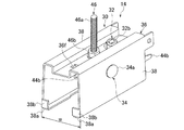
支持部材30の受部36を屋根10の瓦棒16の両はぜ26に固定するための係止部材31は、支持部材30の両脚部38間に配置されている。図4及び図7に示すように、係止部材31は、本体40と、該本体に一対のピン42を介してそれぞれ連なる一対のアーム部44とからなる。両アーム部44はそれぞれ両ピン42の周りに揺動可能である。係止部材31は、好ましくは、支持部材30の前記軸線の伸長方向における中央と該軸線の伸長方向における両端の一方との間であって、取付金具14の使用時に流れ方向Fにおける水上側にあるように配置する。これによれば、支持部材30が前記水上側において瓦棒16の両はぜ26に固定されるため、屋根10上の積雪が水上側から水下側に向けて及ぼす負荷によって支持部材30が水上側において浮き上がることを防止することができる。
The locking
係止部材31の本体40は溝形の板状体からなり、互いに相対する一対の立ち上がり部分40aを有する。両立ち上がり部分40aには互いに整合する二対の孔40bが設けられている。また、各アーム部44は溝形の板状体からなる基部分44aと、該基部分に連なる鉤形の先端部分44bとからなる。基部分44aには互いに整合する一対の孔44cが設けられている。
The
各アーム部44の基部分44aは、その一部において、本体40の両立ち上がり部分40a間に受け入れられ、その両孔44cが本体40各対の孔40bに整合する。互いに整合する両孔44c及び両孔40bにピン42が通されている。これにより、各アーム部44は、本体40に対して、各ピン42の周りに揺動可能とされている。また、両アーム部44の両基部分44aに連なる先端部分44bは、互いに他の一方に向けてわずかに相寄るように、本体40から垂れ下がる。
The
係止部材31は、そのピン42が支持部材30の前記軸線の伸長方向へ伸びるように、支持部材30の両脚部38間に配置され、後に詳述するように、第1の締結部材32により支持部材30の受部36に吊持されている。これによれば、取付金具14の使用時、両アーム部44をピン42の周りに揺動させ又は揺動させることなしに、鉤状の両先端部分44bをそれぞれ屋根10の瓦棒16の二条のはぜ26にその下方から引掛けることができる。このとき、互いに他の一方に向けて相寄るように垂れ下がる両先端部分44bは両はぜ26に対する引掛かり状態を維持する。
The locking
係止部材31は第1の締結部材32により支持部材30の受部36に締結することができる。この締結により、受部36を瓦棒16の両はぜ26に固定することができる。なお、係止部材31は、図示の例に代えて、本体40と両アーム部44とがピン42を介することなしに連続して連なり、両アーム部44が本体40に対して非可動であるものとすることができる(図11参照)。図11に示す係止部材31は、支持部材30の受部36に相対する板状の本体40と、該本体に連なり、支持部材30の両脚部38に沿ってそれぞれ伸びる一対の板状のアーム部44とからなる。両アーム部44は互いに他の一方に向けて伸びる鉤状の先端部分44bを有する。この例においては、両アーム部44の相互間隔が前記はぜ幅と異なるとき、両アーム部44を互いに他の一方に向けて又はその反対方向へ弾性変形させることにより、両アーム部44の相互間隔、より詳細には両先端部分44bの相互間隔の広狭を調整することができる。
The locking
図示の第1の締結部材32は、ボルト32aとこれに螺合されたナット32bとからなる。ボルト32aは、係止部材31の本体40に設けられその両立ち上がり部分40a間の中央を貫通するボルト孔40cと、支持部材30の受部36に設けられ該受部の凹面36bを貫通するボルト孔36cとを順次に経て上方へ伸び、その頭部が係止部材31の本体40に接している。したがって、係止部材31は、第1の締結部材32を介して、受部36に吊持されている。
The
これによれば、ボルト32aが支持部材30の受部36に向けて移動するようにナット32bを回すこと、すなわち締め付け操作を行うことにより、瓦棒16の両はぜ26に係止する係止部材31を受部36に向けて引き寄せ、係止部材31を受部36に締結することができ、これにより、支持部材30をその受部36において瓦棒16に固定することができる。図示の例では、ボルト32aの回り止めのために該ボルトが角根丸頭ボルトで構成され、ボルト孔40cが矩形孔とされている。さらに、ボルト32a及びナット32b相互間の緩み防止のため、支持部材30の受部36と係止部材31の本体40との間に六角ナット32dが配置され、また、ナット32bが緩み止めナットで構成されている。
According to this, by turning the
次に、図示の第2の締結部材34は、ボルト34aとこれに螺合されたナット34bとからなる。ボルト34aは、支持部材30の両脚部38に設けられこれらを貫通する2つのボルト孔38cを経て、支持部材30の前記軸線と直交する方向へ伸び、その頭部が一方の脚部38に接している。他方、ナット34bは他方の脚部38に接している。両ボルト孔38cは、好ましくは、図示したように、前記軸線の伸長方向における中央に位置する。また、両ボルト孔38cは、取付金具14の使用時において瓦棒16の上方に位置する。これらの両ボルト孔38cに通されたボルト34aは両脚部38間を係止部材31の本体40に隣接して伸びている。さらに、図示の例では、ボルト34aが回り止めのために、角根丸頭ボルトで構成され、ボルト孔38cが矩形孔とされている。なお、図7における符号34c、34dは、それぞれボルト34aに通される平座金及びばね座金を示す。
Next, the
これによれば、ナット34bを締め付け方向に回して該ナットとボルト34aの頭部との間隔を狭めることにより、これらの間の両脚部38をこれらが互いに他の一方に向けて相寄るように弾性変形させ、両脚部38の先端部分38aをそれぞれ瓦棒16の両側面16aに押し当てることができる。その結果、支持部材30が両脚部38において瓦棒16に締結され、これに固定される。好ましくは、支持部材30の前記軸線の伸長方向における各端部に、両先端部分38aと共に瓦棒16の両側面16aに当接する、両脚部38の一方から他の一方に向けて突出する一対の突出部38bを設ける。
According to this, by turning the
取付金具14は、その複数個が屋根10の流れ方向Fに間隔をおいて配置され、前記したようにして瓦棒16に固定される。図示の取付金具14は、これに屋根置き設備12を固定するために用いられる前記した固定板28を取付金具14の支持部材30に締結するための第3の締結部材46を備える。
A plurality of the mounting
図7に示すように、第3の締結部材46は、ボルト46aとこれに螺合されたナット46bとからなる。ボルト46aは、支持部材30の受部36に設けられ支持部材30の前記軸線の伸長方向中央において凹面36bを貫通するボルト孔36eを経て上方へ伸びている。固定板28は、これに設けられたボルト孔(図示せず)にボルト46aを通し、該ボルトにナット46bを螺合させ、これを締め付け方向に回すことにより、支持部材30の受部36に締結、固定される。図示の例では、ボルト46aの回り止めのために該ボルトが角根丸頭ボルトで構成され、ボルト孔36eが矩形孔とされている。なお、図7における符号46cは、ボルト46aに通される平座金を示す。
As shown in FIG. 7, the
また、図示の例においては、ボルト46aの挿通用孔として、ボルト孔36eに加えて、さらに、同様のボルト孔36fがボルト孔36eから間隔をおいて設けられ、凹面36bを貫通している。両ボルト孔36e、36fは、取付金具14の使用時、前記屋根面の流れ方向Fにおける水上側及び水下側にそれぞれ位置し、両ボルト孔36e、36fは、これらのうちのいずれか一方が選択的に使用される。
Further, in the illustrated example, in addition to the
水下側に位置するボルト孔36fは、屋根10の軒に最も近接して配置される取付金具14において使用される。ボルト孔36fは、支持部材30の前記軸線の伸長方向における端部(水下側の端部)に近接していることから、水上側に位置するボルト孔36eを使用する場合と比べて、屋根置き設備12下における支持部材30の前記端部の露出長を少なくすることができ、これにより屋根10の外観上の向上が図られる。
The
次に、図8〜図11を参照して、変形例に係る取付金具14について説明する。主たる変形点は、屋根置き設備12の一つである雪止め板(以下、説明の便宜のため、雪止め板12と称する。)に対する適応のために取付金具14の支持部材30に切れ込み50を設けたところにある。図示の雪止め板12は山形鋼のようなアングル材からなり、互いに直交する一片部12a及び他片部12bを有する。雪止め板12はその一部である一片部12aにおいて支持部材30の受部36上に載置される。このとき、切れ込み50が雪止め板12の他の一部である他片部12bの挿通を許す。
Next, the mounting
図8に示すように、雪止め板12は屋根10の複数の瓦棒16にそれぞれ固定された複数の取付金具14を介して、複数の瓦棒16の上方に配置され、これらの瓦棒16に直交する方向へ伸びる。なお、図8には、はぜ式瓦棒葺きの屋根10の他の一例として、図1に示す屋根10とは異なるタイプのものが示されている。この屋根10のはぜ式瓦棒葺きは「嵌合式縦平葺き」と称され、二条のはぜ26を有する複数の瓦棒16が、それぞれ、互いに隣接する2つの溝板20の折り返し端部の一方が他方に嵌合されてなる。
As shown in FIG. 8, the
図9〜図11に示すように、支持部材30の切れ込み50は、支持部材30の受部36からその両脚部38の一部分に至る。より詳細には、切れ込み50は、受部36から該受部をその伸長方向(取付金具14の使用時における屋根10の流れ方向F(図8))に直角な方向へ横切って両脚部38をこれらの高さ方向におけるほぼ中央まで伸びている。切れ込み50は、雪止め板12の他片部12bの挿通を許すように、雪止め板12の他片部12bの厚さ寸法よりわずかに大きい幅寸法と、雪止め板12の他片部12bの幅寸法よりわずかに大きい深さ寸法とを有する。また、切れ込み50は、支持部材30の受部36の前記伸長方向に関する任意の位置に設けることができる。図示の例において、切れ込み50は、受部36の前記伸長方向に関する一端(取付金具14の使用時において屋根10の水下側の一端)から他端へ雪止め板12の一片部12aの幅寸法にほぼ相当する距離をおいた位置にある。この切れ込み50により、受部36は2つの部分である長さ寸法が比較的小さい短部分36Aと比較的大きい長部分36Bとに分かたれている。
As shown in FIGS. 9 to 11, the
支持部材30の受部36は、図5に示す一対の平坦面36a及び凹面36bを有するものに代えて、図11に示すように平坦面36dのみを有するものとすることができる。取付金具14の使用時、雪止め板12はその一片部12aにおいて受部36の短部分36A上に載置され、固定板28を介して、支持部材30に固定される。
The receiving
固定板28は、全体に箱状を呈する一端部28aと折り曲げられてなる他端部28bとを有する。固定板28は、その一端部28aにおいて受部36の長部分36B上に載置されかつこれに固定され、その他端部28bにおいて雪止め板12の一片部12aを受部36に押し付け、雪止め板12を受部36上に固定する作用をなす。
The fixing
固定板28は、係止部材31を受部36に吊持する第1の締結部材32を介して、受部36に固定される。図示の係止部材31は、前記したように、支持部材30の受部36に相対する板状の本体40と、該本体に連なり、支持部材30の両脚部38に沿ってそれぞれ伸びる一対の板状のアーム部44とからなり、両アーム部44はそれぞれ互いに他の一方に向けて伸びる鉤状の先端部分44bを有する。
The fixing
第1の締結部材32のボルト32a、より詳細にはその軸部は、係止部材31の本体40に設けられ該本体を貫通するボルト孔40c及び受部36の長部分36Bに設けられ該長部分を貫通するボルト孔36cを経て伸び、さらに、固定板28の一端部28aに設けられ該一端部を貫通するボルト孔28cを経て伸び、これにナット32bが螺合されている。
The
取付金具14の使用時において、係止部材31の両先端部分44bをそれぞれ屋根10の瓦棒16の両はぜ26に引掛けた後、第1の締結部材32のナット32bを回転操作する。これにより、係止部材31が支持部材30の受部36に向けて移動し、第1の締結部材32を介して受部36に固定される。その結果、支持部材30が瓦棒16の両はぜ26に締結、固定される。その後、固定板28の一端部28aを貫通する第1の締結部材32のボルト32aにナット32eを螺合させ、これを締め付け方向に回転操作する。これにより、固定板28を受部36に固定することができる。
When the mounting
図示の例では、第2の締結部材34、より詳細にはそのボルト34aが係止部材31の両アーム部44を貫通している。係止部材31の両アーム部44はそれぞれボルト34aの貫通を許す、本体40に向けて伸びる長穴44dを有する。両長穴44dは、第1の締結部材32のナット32bの回転操作時における支持部材30の受部36に向けて係止部材31の移動を許す長さ寸法を有する。
In the illustrated example, the
なお、図示の例においては、支持部材30の受部36に対する固定板28の回転が生じないように、固定板28の一端部28aに一対の突起28cが設けられ、また、受部36に両突起28cをそれぞれ受け入れ可能の穴36eが設けられている。
In the illustrated example, a pair of
図示の例においては、また、各取付金具14に「羽根」と称される比較的長さの短い雪止め板(図示せず)を取り付けるためのボルト孔36gが設けられている。ボルト孔36gは支持部材30の受部36の短部分36Aに設けられている。前記「羽根」は、雪止め作用をなす細長い板部と該板に直交する、ボルト孔が設けられた舌部とを有する。これによれば、前記「羽根」は、その細長い板部が(取付金具14の使用時において屋根10の水下側に位置する)支持部材30の一端30aに面しかつ前記舌部が支持部材30の受部36上に位置するように配置され、前記舌部のボルト孔及び受部36のボルト孔36gとにボルトを通し、該ボルトにナットを螺合させてこれを締め付けることにより、各取付金具14に取り付けられる。
In the illustrated example, each mounting
さらに、支持部材30の両脚部38は、使用時に前記屋根面に当接する二対の先端部分であって互いに他の一方に対して反対方向へ伸びる二対の先端部分30dを有する。これらの先端部分30dは、前記屋根面上における取付金具14の姿勢保持に寄与する。
Further, both
10 屋根
12 屋根置き設備
14 取付金具
16 屋根の瓦棒
26 瓦棒のはぜ
30 支持部材
31 係止部材
32 第1の締結部材
34 第2の締結部材
36 支持部材における受部
38 支持部材における脚部
40 係止部材における本体
44 係止部材におけるアーム部
46 第3の締結部材
10
Claims (8)
使用時に前記屋根の瓦棒の上方において前記屋根置き設備の載置を受ける受部及び該受部に連なり、使用時に前記瓦棒の両側に位置する一対の脚部とを有する支持部材と、
前記支持部材の両脚部間に配置された、前記瓦棒の二条のはぜに係止される係止部材と、
前記支持部材の受部と前記係止部材とを締結するための第1の締結部材と、
前記支持部材の両脚部を前記瓦棒に締結するための第2の締結部材とを備え、
前記支持部材の両脚部は、それぞれ、両脚部が前記第2の締結部材により前記瓦棒に締結されるときに前記瓦棒の両側面に押し当てられる互いに他の一方に向けて伸びる一対の先端部分を有し、両先端部分は、それぞれ、使用時に屋根面に当接し、
前記係止部材は、本体と、該本体に一対のピンを介してそれぞれ連なる、鉤状の先端部分を有する一対のアーム部とからなる、取付金具。 A mounting bracket used to attach roofing equipment to a roof tiled roof.
A support member having a receiving portion on which the roof-standing equipment is placed above the roof tile bar during use and a pair of legs connected to the receiving portion and located on both sides of the roof tile bar during use.
A locking member arranged between both legs of the support member and locked to the two gobies of the tile bar,
A first fastening member for fastening the receiving portion of the support member and the locking member,
A second fastening member for fastening both legs of the support member to the tile bar is provided.
Both legs of the support member are a pair of tips extending toward the other one, which are pressed against both side surfaces of the tile bar when both legs are fastened to the tile bar by the second fastening member. has a portion, both ends portions, respectively, come into contact with the roof surface during use,
The locking member is a mounting bracket including a main body and a pair of arm portions having a hook-shaped tip portion connected to the main body via a pair of pins .
前記第1の締結部材は、前記凹面を貫通するボルトと前記凹面内に受け入れられ前記ボルトに螺合されたナットとからなる、請求項1記載の取付金具。 The receiving portion of the support member has a pair of flat surfaces extending in the flow direction of the roof surface forming a mounting surface of the roof-standing equipment, and a concave surface extending between the two flat surfaces in the flow direction of the roof surface. ,
The mounting bracket according to claim 1, wherein the first fastening member comprises a bolt penetrating the concave surface and a nut received in the concave surface and screwed into the bolt.
使用時、前記支持部材は前記一のボルト孔と他のボルト孔とが前記屋根の流れ方向に沿って位置するように配置される、請求項3に記載の取付金具。 The third fastening member includes a bolt extending through one of a bolt hole and another bolt hole provided at a distance from each other in a receiving portion of the support member, and a nut screwed into the bolt. Consists of
The mounting bracket according to claim 3, wherein the support member is arranged so that the one bolt hole and the other bolt hole are located along the flow direction of the roof when used.
前記支持部材は、前記受部から前記両脚部の一部分に至る、前記雪止め板の一部の挿通を許す切れ込みを有する、請求項1に記載の取付金具。 The roof-standing equipment consists of snow stoppers.
The mounting bracket according to claim 1, wherein the support member has a notch that allows a part of the snow stopper plate to be inserted from the receiving portion to a part of both leg portions.
前記固定板は前記第1の締結部材を介して前記支持部材の受部に固定される、請求項6に記載の取付金具。 Further, a fixing plate for fixing the snow stopper plate is provided on the receiving portion of the support member.
The mounting bracket according to claim 6 , wherein the fixing plate is fixed to a receiving portion of the support member via the first fastening member.
Applications Claiming Priority (2)
| Application Number | Priority Date | Filing Date | Title |
|---|---|---|---|
| JP2015134983 | 2015-07-06 | ||
| JP2015134983 | 2015-07-06 |
Publications (2)
| Publication Number | Publication Date |
|---|---|
| JP2017014886A JP2017014886A (en) | 2017-01-19 |
| JP6814543B2 true JP6814543B2 (en) | 2021-01-20 |
Family
ID=57830115
Family Applications (1)
| Application Number | Title | Priority Date | Filing Date |
|---|---|---|---|
| JP2016027677A Active JP6814543B2 (en) | 2015-07-06 | 2016-02-17 | Mounting bracket for roof-standing equipment |
Country Status (1)
| Country | Link |
|---|---|
| JP (1) | JP6814543B2 (en) |
Families Citing this family (1)
| Publication number | Priority date | Publication date | Assignee | Title |
|---|---|---|---|---|
| JP2021092085A (en) * | 2019-12-11 | 2021-06-17 | 株式会社ノミズヤ産業 | Snow stopping metal fitting |
Family Cites Families (5)
| Publication number | Priority date | Publication date | Assignee | Title |
|---|---|---|---|---|
| JPS5023459Y1 (en) * | 1970-10-19 | 1975-07-15 | ||
| US4189881A (en) * | 1979-03-12 | 1980-02-26 | Atlantic Richfield Company | Photovoltaic roof construction |
| JP2007023758A (en) * | 2005-06-15 | 2007-02-01 | Shigero Sasamoto | Metal fittings for attaching superstructure on roof |
| JP6050022B2 (en) * | 2012-04-24 | 2016-12-21 | 三晃金属工業株式会社 | Building fixture |
| JP5999771B2 (en) * | 2013-05-21 | 2016-09-28 | Jfe鋼板株式会社 | Attachment for roof installation and method of attaching installation for roof using the attachment |
-
2016
- 2016-02-17 JP JP2016027677A patent/JP6814543B2/en active Active
Also Published As
| Publication number | Publication date |
|---|---|
| JP2017014886A (en) | 2017-01-19 |
Similar Documents
| Publication | Publication Date | Title |
|---|---|---|
| US8453407B2 (en) | Seismic clip | |
| US6415560B1 (en) | Seismic bracing connector | |
| JP5295306B2 (en) | Brace fixing bracket | |
| US4949519A (en) | Fastener arrangement for securing an edge cap to an upstanding wall panel | |
| KR101467161B1 (en) | A fixing device for grating panel | |
| US10202805B2 (en) | Roof mounted ladder safety bracket | |
| JP6814543B2 (en) | Mounting bracket for roof-standing equipment | |
| JP5732950B2 (en) | Seismic structure of suspended ceiling | |
| US8985535B1 (en) | Wind resilient mast arm mounting assembly | |
| EP2844929A1 (en) | Rail clamp | |
| JP6778090B2 (en) | Hanger and system ceiling structure using the hanger | |
| JP6110835B2 (en) | Latch | |
| BR112019015035A2 (en) | CONSOLE FOR FIXING ELEMENTS OF FACADE | |
| KR101929337B1 (en) | Deck structure and construction method | |
| JP4782536B2 (en) | Ceiling base member mounting structure | |
| JP6117961B1 (en) | Suspended ceiling foundation structure on sloped roof and method of repairing existing suspended ceiling foundation | |
| US4720954A (en) | Screen ceiling assembly | |
| US7066440B2 (en) | Waler bracket with attached wedge for concrete forms | |
| JP7400176B2 (en) | Snow stopper with safety device retention function and snow stopper installation method | |
| JP3182622U (en) | Mounting bracket | |
| KR200410682Y1 (en) | Prop For Fence | |
| GB2364720A (en) | Fixing for co-operation with re-entrant groove | |
| JP6708881B2 (en) | Suspension device | |
| JP6927795B6 (en) | Eaves gutter support tool and eaves gutter support method | |
| KR200362896Y1 (en) | Ceiling board supported apparatus |
Legal Events
| Date | Code | Title | Description |
|---|---|---|---|
| A621 | Written request for application examination |
Free format text: JAPANESE INTERMEDIATE CODE: A621 Effective date: 20190125 |
|
| A977 | Report on retrieval |
Free format text: JAPANESE INTERMEDIATE CODE: A971007 Effective date: 20191111 |
|
| A131 | Notification of reasons for refusal |
Free format text: JAPANESE INTERMEDIATE CODE: A131 Effective date: 20191210 |
|
| A521 | Request for written amendment filed |
Free format text: JAPANESE INTERMEDIATE CODE: A523 Effective date: 20200207 |
|
| A131 | Notification of reasons for refusal |
Free format text: JAPANESE INTERMEDIATE CODE: A131 Effective date: 20200804 |
|
| A521 | Request for written amendment filed |
Free format text: JAPANESE INTERMEDIATE CODE: A523 Effective date: 20200929 |
|
| TRDD | Decision of grant or rejection written | ||
| A01 | Written decision to grant a patent or to grant a registration (utility model) |
Free format text: JAPANESE INTERMEDIATE CODE: A01 Effective date: 20201208 |
|
| A61 | First payment of annual fees (during grant procedure) |
Free format text: JAPANESE INTERMEDIATE CODE: A61 Effective date: 20201221 |
|
| R150 | Certificate of patent or registration of utility model |
Ref document number: 6814543 Country of ref document: JP Free format text: JAPANESE INTERMEDIATE CODE: R150 |
|
| R250 | Receipt of annual fees |
Free format text: JAPANESE INTERMEDIATE CODE: R250 |