EP2581496A2 - Blade holder for road maintenance plough - Google Patents
Blade holder for road maintenance plough Download PDFInfo
- Publication number
- EP2581496A2 EP2581496A2 EP12187848.2A EP12187848A EP2581496A2 EP 2581496 A2 EP2581496 A2 EP 2581496A2 EP 12187848 A EP12187848 A EP 12187848A EP 2581496 A2 EP2581496 A2 EP 2581496A2
- Authority
- EP
- European Patent Office
- Prior art keywords
- blade holder
- blade
- elastically deforming
- plough
- road maintenance
- Prior art date
- Legal status (The legal status is an assumption and is not a legal conclusion. Google has not performed a legal analysis and makes no representation as to the accuracy of the status listed.)
- Granted
Links
Images



Classifications
-
- E—FIXED CONSTRUCTIONS
- E01—CONSTRUCTION OF ROADS, RAILWAYS, OR BRIDGES
- E01H—STREET CLEANING; CLEANING OF PERMANENT WAYS; CLEANING BEACHES; DISPERSING OR PREVENTING FOG IN GENERAL CLEANING STREET OR RAILWAY FURNITURE OR TUNNEL WALLS
- E01H5/00—Removing snow or ice from roads or like surfaces; Grading or roughening snow or ice
- E01H5/04—Apparatus propelled by animal or engine power; Apparatus propelled by hand with driven dislodging or conveying levelling elements, conveying pneumatically for the dislodged material
- E01H5/06—Apparatus propelled by animal or engine power; Apparatus propelled by hand with driven dislodging or conveying levelling elements, conveying pneumatically for the dislodged material dislodging essentially by non-driven elements, e.g. scraper blades, snow-plough blades, scoop blades
- E01H5/061—Apparatus propelled by animal or engine power; Apparatus propelled by hand with driven dislodging or conveying levelling elements, conveying pneumatically for the dislodged material dislodging essentially by non-driven elements, e.g. scraper blades, snow-plough blades, scoop blades by scraper blades
- E01H5/062—Apparatus propelled by animal or engine power; Apparatus propelled by hand with driven dislodging or conveying levelling elements, conveying pneumatically for the dislodged material dislodging essentially by non-driven elements, e.g. scraper blades, snow-plough blades, scoop blades by scraper blades by scraper blades displaceable for shock-absorbing purposes
Definitions
- the invention is related to the field of mechanical engineering, namely to the field of blade constructions for road and large area maintenance equipment.
- Blade constructions for road maintenance vehicles, scrapers and snow ploughs are known from the prior art.
- Patent application publication WO 2004/031490 discloses the blade holder, in the form of a beam, connecting a blade to the lower edge of a snow-clearing device so that the blade has been given a definite angle to the base.
- the beam enables the lower part of the blade to fold backwards, thereby preventing possible damage to the blade when running into an obstacle on the road. After passing the obstacle, the blade resumes its original position
- US5743032 discloses a grader blade; preferably a snow plough blade construction intended to be attached preferably to a tractor or lorry.
- the grader blade construction includes a frame consisting of a flat part that is detachable from the grader, and several blade plates covering the desired working width; whereas there is a section consisting of elastic material between the blade plates.
- the elastic material is arranged to permit the movement of the blade plates in only one direction when the blade plate strikes an obstacle.
- DE 2519112 discloses a grader construction in which a blade is attached to a moldboard with an elastic section that enables, if an obstacle is encountered, the blade to trip and then resume its original position
- DE 3640565 discloses a clearing edge of a snow grader blade.
- the clearing edge includes a rubber or plastic fastening element that has a fastening strip on one end and the blade on the other end, whereas the fastening element has sufficient horizontal and vertical movement, so that road irregularities does not cause the blade to jump or break
- DE 2552058 discloses a snow plough construction in which a blade is attached to the moldboard of the plough with an elastic section that enables, if an obstacle is encountered, the blade to trip and then resume its original position.
- DE 4204109 discloses a snow grader designed to be fixed to a vehicle or tractor.
- a supporting frame is attached to the snow grader.
- a flexible spring guide is fixed on the underside of the supporting frame.
- a metal strip which is in contact with the road surface, is attached; whereby the metal strip is fixed to the underside of the grader with another band of elastic material.
- the angle of the blade changes significantly with the up and down movement of the blade holders, since natural behaviour of the parallelogram is absent, which results in the bouncing of the snow plough when crossing road irregularities.
- the purpose of this invention is to offer an elastically deforming, including from elastomeric material, snow plough blade holder construction; whereas a blade equipped with this elastic blade holder allows for the irregularities of a processed surface to be followed.
- the invention's blade holder includes an elaslically deforming material part, in which there are one or several gaps, as a result of which the blade holder functions in a manner similar to a parallelogram (four bar linkage). In addition to this, the blade holder deforms elastically more easily due to one or several gaps in comparison with analogous gapless constructions.
- the blade holder of this invention comprises of short, adjacently located modules. By being placed next to one another, these modules allow blades of various widths to be used according to need. By using blades of various widths it is possible to vary the rigidity of the blade holders and the ability to copy the road surface. At the same time, it is also possible to attach only one short blade to a module. This makes the blade holder module universal for all snow ploughs of varying widths.
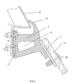
- FIG. 1 illustrates the new principle blade holder 1 made of an elastically deforming material, which is comprised of an elastically deforming material part 2 and the attachment plate 3 for the blade placed within.
- the elastically deforming material part 2 operates on the principle of a parallelogram. It differs from existing blade holders with elastically deforming details in that the blade holder has one or several gaps 4, as a result of which the blade holder operates in a manner similar to a parallelogram (four bar linkage). In addition to this, the blade holder deforms elastically more easily due to one or several gaps, in comparison to similar gapless constructions.
- the blade holder is comprised of four joints: the topmost moving joint 5, the lower moving joint 6, the front moving joint 7 and the rear moving joint 8. The joints are connected to each other conditionally with hinges 9. The result of the newly shaped blade holder ensures the excellent kinematics of the elastically deforming parts, sufficient rigidity and at the same time endurance.
- the blade holder 1 of the invention is made from elastically deforming material part 2 is attached to the holder 11 located along the bottom edge of the plough's moldboard 10 with attachment bolts 13 extending from the mounting plate 12 poured inside the part 2.
- Attached to the blade's mounting plate 3 is a snow plough blade 14.
- a sealing strip 15 extends outward from the upper edge of the elastically deforming material part 2, which prevents snow from ending up in the blade holder's gaps.
- Figure 3A-3C illustrates the plough's blade holder in its working position and the plough's blade position on a smooth surface ( Figure 3A ), in the case of an obstacle with evenly rising edges ( Figure 3B ), and in the case of incremental obstacles ( Figure 3C ).
- the lower joint 6) ( Figure 1 ) of part 2 made from elastically deforming material gives way according to the principle of a parallelogram and the snow plough's blade 13 is able to move backward while at the same time moving upwards, allowing the obstacle to be crossed.
- the blade can move up and down in relation to the snow plough's moldboard 10, remaining at approximately the same angle to the surface of the ground.
- the given blade holder permits greater upward movement of the blade in comparison with the known solutions, thereby permitting improved coping of the road surface when crossing over rounded obstacles.
- the invented blade holder 1 may be in a single piece that is the entire width of the plough's moldboard or may be comprised of short modules. By being placed next to one another, these modules allow blades of various widths to be used according to need. By using blades of various widths it is possible to vary the rigidity of the blade holders and the ability to copy the road surface. At the same time, it is also possible to attach only one short blade to a module. This makes the blade holder module universal for all snow ploughs of varying widths.
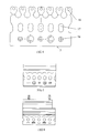
- the positions of attachment openings 16 ( Figure 4 ) in the blade 13 attachment plate 3 are selected in such a manner to allow attachment of all snow plough blades of standard measurements and several different nonstandard measurements.
- the attachment plate 3 has openings 17 for the improved connectedness between the elastically deforming material (such as elastomer) part 2 and the attachment plate 3.
- the attachment plate 3 has attachment anchors 18 to improve the connectedness between the elastomer and the attachment plate 3.
- Suitable radius of curvature notches (19 and 20) help in permitting the natural movement of the articulation of the elastically deforming material (elastomer) characteristic of a parallelogram.
- a suitable radius of curvature notch 21 permits the sealing strip 15 to adjust according to the snow plough's moldboard in the case of the various working positions of the blade holder.
- the blade attachment plate 3 may be bent (see Figures 9 to 12 ), in order to avoid its breaking out from the elastomer.
- the blade holder may be equipped with additional anchors 22.
- the blade holder 1 on the beam side 11 has a step 23 ( Figure 8 ) on one side.
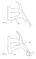
- FIG 11 illustrates one of the possible alternative implementations of a blade holder, where the elastically deforming material (elastomer) part 2 has a suitable radius of curvature notch 24 which ensures the greater buckling of the lower joint when crossing over a graduated obstacle.
- Figure 12 illustrates a blade holder 2, the bottom of which has an extending part 25, which is designed for restricting the movement of the blade holder upon hitting an obstacle, blade attachment bolt 26 (see Figure 2 ) protection 27 in the case of the buckling of the elastically deforming material (elastomer) part 2.
- the elastically deforming material (elastomer) part 2 has an elevation of 28, which restricts the buckling of the lower joint 6.
Landscapes
- Engineering & Computer Science (AREA)
- Architecture (AREA)
- Civil Engineering (AREA)
- Structural Engineering (AREA)
- Cleaning Of Streets, Tracks, Or Beaches (AREA)
- Fittings On The Vehicle Exterior For Carrying Loads, And Devices For Holding Or Mounting Articles (AREA)
- Soil Working Implements (AREA)
Abstract
Description
- The invention is related to the field of mechanical engineering, namely to the field of blade constructions for road and large area maintenance equipment.
- Blade constructions for road maintenance vehicles, scrapers and snow ploughs are known from the prior art.
- Patent application publication
WO 2004/031490 discloses the blade holder, in the form of a beam, connecting a blade to the lower edge of a snow-clearing device so that the blade has been given a definite angle to the base. The beam enables the lower part of the blade to fold backwards, thereby preventing possible damage to the blade when running into an obstacle on the road. After passing the obstacle, the blade resumes its original positionUS5743032 discloses a grader blade; preferably a snow plough blade construction intended to be attached preferably to a tractor or lorry. The grader blade construction includes a frame consisting of a flat part that is detachable from the grader, and several blade plates covering the desired working width; whereas there is a section consisting of elastic material between the blade plates. The elastic material is arranged to permit the movement of the blade plates in only one direction when the blade plate strikes an obstacle. -
DE 2519112 discloses a grader construction in which a blade is attached to a moldboard with an elastic section that enables, if an obstacle is encountered, the blade to trip and then resume its original position -
DE 3640565 discloses a clearing edge of a snow grader blade. The clearing edge includes a rubber or plastic fastening element that has a fastening strip on one end and the blade on the other end, whereas the fastening element has sufficient horizontal and vertical movement, so that road irregularities does not cause the blade to jump or break -
DE 2552058 discloses a snow plough construction in which a blade is attached to the moldboard of the plough with an elastic section that enables, if an obstacle is encountered, the blade to trip and then resume its original position. -
DE 4204109 discloses a snow grader designed to be fixed to a vehicle or tractor. A supporting frame is attached to the snow grader. On the underside of the supporting frame a flexible spring guide is fixed. On the other end of the spring a metal strip, which is in contact with the road surface, is attached; whereby the metal strip is fixed to the underside of the grader with another band of elastic material. Such construction enables, if an obstacle is encountered, the blade to trip and then resume its original position. - The deficiency of the known constructions is that in the case of an obstacle on the road surface the grader blade trips and the angle between the blade and the road surface changes, as a result of which cleaning efficiency is reduced during the period when the blade is clearing the obstacle.
- The angle of the blade changes significantly with the up and down movement of the blade holders, since natural behaviour of the parallelogram is absent, which results in the bouncing of the snow plough when crossing road irregularities.
- The purpose of this invention is to offer an elastically deforming, including from elastomeric material, snow plough blade holder construction; whereas a blade equipped with this elastic blade holder allows for the irregularities of a processed surface to be followed. The invention's blade holder includes an elaslically deforming material part, in which there are one or several gaps, as a result of which the blade holder functions in a manner similar to a parallelogram (four bar linkage). In addition to this, the blade holder deforms elastically more easily due to one or several gaps in comparison with analogous gapless constructions.
- The blade holder of this invention comprises of short, adjacently located modules. By being placed next to one another, these modules allow blades of various widths to be used according to need. By using blades of various widths it is possible to vary the rigidity of the blade holders and the ability to copy the road surface. At the same time, it is also possible to attach only one short blade to a module. This makes the blade holder module universal for all snow ploughs of varying widths.
- The preferred application of the invention is described by making reference to the accompanying drawings, where:
-
Figure 1 illustrates the similarity of the cross section of the invented blade holder to a parallelogram; -
Figure 2 illustrates a cross section of one of the preferred implementations of the invented blade holder made from elastically deforming material; -
Figures 3A, 3B and 3C , illustrate the shape of the invented blade holder made from elastically deforming material changed in accordance with the irregularities in the road surface; -
Figure 4 illustrates a top view of the blade attachment plate of the invented blade holder made from elastically deforming material; -
Figure 5 illustrates a front view of the invented blade holder made from elastically deforming material; -
Figure 6 illustrates a top view of the invented blade holder made from elastically deforming material; -
Figure 7 illustrates a side view of the invented blade holder made from elastically deforming material; -
Figure 8 illustrates section A-A ofFigure 6 ; -
Figure 9 illustrates a cross section of the preferred implementation of the invented blade holder made from elastically deforming material; -
Figure 10 illustrates an axonometric view with a partial cross section of the invented blade holder made from elastically deforming material; -
Figure 11 illustrates a side view of an alternative implementation of the invented blade holder made from elastically deforming material; -
Figure 12 illustrates a side view of another alternative implementation of the invented blade holder made from elastically deforming material. -
Figure 1 illustrates the newprinciple blade holder 1 made of an elastically deforming material, which is comprised of an elastically deformingmaterial part 2 and theattachment plate 3 for the blade placed within. The elastically deformingmaterial part 2 operates on the principle of a parallelogram. It differs from existing blade holders with elastically deforming details in that the blade holder has one orseveral gaps 4, as a result of which the blade holder operates in a manner similar to a parallelogram (four bar linkage). In addition to this, the blade holder deforms elastically more easily due to one or several gaps, in comparison to similar gapless constructions. The blade holder is comprised of four joints: the topmost movingjoint 5, the lower movingjoint 6, thefront moving joint 7 and the rear movingjoint 8. The joints are connected to each other conditionally withhinges 9. The result of the newly shaped blade holder ensures the excellent kinematics of the elastically deforming parts, sufficient rigidity and at the same time endurance. - According to
Figure 2 , theblade holder 1 of the invention is made from elastically deformingmaterial part 2 is attached to theholder 11 located along the bottom edge of the plough'smoldboard 10 withattachment bolts 13 extending from themounting plate 12 poured inside thepart 2. Attached to the blade'smounting plate 3 is asnow plough blade 14. Asealing strip 15 extends outward from the upper edge of the elastically deformingmaterial part 2, which prevents snow from ending up in the blade holder's gaps. -
Figure 3A-3C illustrates the plough's blade holder in its working position and the plough's blade position on a smooth surface (Figure 3A ), in the case of an obstacle with evenly rising edges (Figure 3B ), and in the case of incremental obstacles (Figure 3C ). In the case of graded obstacles, which do not permit the blade to freely move up and down, the lower joint 6) (Figure 1 ) ofpart 2 made from elastically deforming material gives way according to the principle of a parallelogram and the snow plough'sblade 13 is able to move backward while at the same time moving upwards, allowing the obstacle to be crossed. Therefore, due to the presence of one or several gaps in thepart 2 of the snow plough'sblade 13 made from elastically deforming material, the blade can move up and down in relation to the snow plough'smoldboard 10, remaining at approximately the same angle to the surface of the ground. The given blade holder permits greater upward movement of the blade in comparison with the known solutions, thereby permitting improved coping of the road surface when crossing over rounded obstacles. - The invented
blade holder 1 may be in a single piece that is the entire width of the plough's moldboard or may be comprised of short modules. By being placed next to one another, these modules allow blades of various widths to be used according to need. By using blades of various widths it is possible to vary the rigidity of the blade holders and the ability to copy the road surface. At the same time, it is also possible to attach only one short blade to a module. This makes the blade holder module universal for all snow ploughs of varying widths. - The positions of attachment openings 16 (
Figure 4 ) in theblade 13attachment plate 3 are selected in such a manner to allow attachment of all snow plough blades of standard measurements and several different nonstandard measurements. Theattachment plate 3 hasopenings 17 for the improved connectedness between the elastically deforming material (such as elastomer)part 2 and theattachment plate 3. In addition, theattachment plate 3 has attachment anchors 18 to improve the connectedness between the elastomer and theattachment plate 3. - The detailed technical solution of the blade holder is illustrated in
Figure 9 . Suitable radius of curvature notches (19 and 20) help in permitting the natural movement of the articulation of the elastically deforming material (elastomer) characteristic of a parallelogram. A suitable radius ofcurvature notch 21 permits the sealingstrip 15 to adjust according to the snow plough's moldboard in the case of the various working positions of the blade holder. Theblade attachment plate 3 may be bent (seeFigures 9 to 12 ), in order to avoid its breaking out from the elastomer. In order to ensure better adhesion, the blade holder may be equipped withadditional anchors 22. To allow for the removal of snow, theblade holder 1 on thebeam side 11 has a step 23 (Figure 8 ) on one side. - The blade holder may have different types of modifications.
Figure 11 illustrates one of the possible alternative implementations of a blade holder, where the elastically deforming material (elastomer)part 2 has a suitable radius ofcurvature notch 24 which ensures the greater buckling of the lower joint when crossing over a graduated obstacle.Figure 12 illustrates ablade holder 2, the bottom of which has an extendingpart 25, which is designed for restricting the movement of the blade holder upon hitting an obstacle, blade attachment bolt 26 (seeFigure 2 )protection 27 in the case of the buckling of the elastically deforming material (elastomer)part 2. In another alternative implementation the elastically deforming material (elastomer)part 2 has an elevation of 28, which restricts the buckling of thelower joint 6.
Claims (10)
- Blade holder for road maintenance plough (1) for attaching the blade (14) to the plough's moldboard (10), which is comprised of the attachment part for the attachment of the blade holder to the plough's moldboard and a blade attachment part for attachment to the blade holder, characterised in that the blade holder comprises an elastically deforming material part (2), in which there are one or more gaps so that the blade holder is adjusted to operate as a parallelogram, which has an upper moving joint (5), a lower moving joint (6), a front moving joint (7) and a rear moving joint (8), comprises an attachment plate (3) and connection plate (12) placed inside the elastically deforming material part (2).
- Blade holder for road maintenance plough according to the claim 1, characterised in that the attachment plate (3) is rectangular shaped.
- Blade holder for road maintenance plough according to the claim 1, characterised in that the upper part of the attachment plate (3) is bent.
- Blade holder for road maintenance plough according to the claim 1, characterised in that a sealing strip (15) extends out from the upper edge of the elastically deforming material part (2).
- Blade holder for road maintenance plough according to the claim 1, characterised in that the blade holder (1) is comprised of adjacently located modules.
- Blade holder for road maintenance plough according to the claim 1, characterised in that the attachment plate (3) has openings (17) for achieving improved connectedness between the elastically deforming material part (2) and the attachment plate (3) and the attachment plate (3) has attachment anchors (18).
- Blade holder for road maintenance plough according to the claim 1, characterised in that the elastically deforming material part (2) has one or more selected of the following: notch (19), notch (20), notch (21), and notch (24).
- Blade holder for road maintenance plough according to the claim 1, characterised in that the elastically deforming material part (2) has one or more anchors (22), elevation (28), pad (25), and protection (27).
- Blade holder for road maintenance plough according to the claim 1, characterised in that the attachment plate (3) and the connection plate (12) are covered with a coating prior to being placed in the elastically deforming material part (2).
- Blade holder for road maintenance plough according to the claim 1, characterised in that the elastically deforming material part (2) has a step (23).
Priority Applications (1)
| Application Number | Priority Date | Filing Date | Title |
|---|---|---|---|
| PL12187848T PL2581496T3 (en) | 2011-10-10 | 2012-10-09 | Blade holder for road maintenance plough |
Applications Claiming Priority (1)
| Application Number | Priority Date | Filing Date | Title |
|---|---|---|---|
| EEP201100057A EE05739B1 (en) | 2011-10-10 | 2011-10-10 | Plough blade holder of a road maintenance vehicle |
Publications (3)
| Publication Number | Publication Date |
|---|---|
| EP2581496A2 true EP2581496A2 (en) | 2013-04-17 |
| EP2581496A3 EP2581496A3 (en) | 2015-03-11 |
| EP2581496B1 EP2581496B1 (en) | 2021-01-27 |
Family
ID=47010371
Family Applications (1)
| Application Number | Title | Priority Date | Filing Date |
|---|---|---|---|
| EP12187848.2A Active EP2581496B1 (en) | 2011-10-10 | 2012-10-09 | Blade holder for road maintenance plough |
Country Status (3)
| Country | Link |
|---|---|
| EP (1) | EP2581496B1 (en) |
| EE (1) | EE05739B1 (en) |
| PL (1) | PL2581496T3 (en) |
Cited By (1)
| Publication number | Priority date | Publication date | Assignee | Title |
|---|---|---|---|---|
| EP3020866A3 (en) * | 2014-11-13 | 2016-08-31 | Meiren Engineering OÜ | Plough blade holder of a road maintenance vehicle |
Citations (6)
| Publication number | Priority date | Publication date | Assignee | Title |
|---|---|---|---|---|
| DE2519112A1 (en) | 1975-04-29 | 1976-11-04 | Gottfried Dr Reissinger | Jolt-absorbing mount for snow plough or road-sweeper ploughshare - has elastically deformable support connected to scraper bar |
| DE2552058A1 (en) | 1975-11-20 | 1977-05-26 | Beilhack Maschf Martin | Snow plough resilient sweeper bar hinge mounting - has hollow triangular sectioned elastic unit clamped to bar and bracket |
| DE3640565A1 (en) | 1986-11-27 | 1988-06-09 | Hoesch Ag | Clearing strip for the clearing blade of a snow plough |
| DE4204109A1 (en) | 1992-02-12 | 1993-08-19 | Beilhack Sued Vertriebs Gmbh | Snowplough with sprung lower support - has support made of elastic material with fixing clamp on plough higher than fixing clamp on support frame |
| US5743032A (en) | 1993-01-22 | 1998-04-28 | Vauhkonen; Pertti | Plough blade arrangement |
| WO2004031490A1 (en) | 2002-10-03 | 2004-04-15 | Kaellqvist Goesta | Blade holder for a snow-cleaning device |
Family Cites Families (1)
| Publication number | Priority date | Publication date | Assignee | Title |
|---|---|---|---|---|
| SE9700046L (en) * | 1997-01-09 | 1998-06-22 | Goesta Kaellqvist | Plow cutter holder |
-
2011
- 2011-10-10 EE EEP201100057A patent/EE05739B1/en not_active IP Right Cessation
-
2012
- 2012-10-09 EP EP12187848.2A patent/EP2581496B1/en active Active
- 2012-10-09 PL PL12187848T patent/PL2581496T3/en unknown
Patent Citations (6)
| Publication number | Priority date | Publication date | Assignee | Title |
|---|---|---|---|---|
| DE2519112A1 (en) | 1975-04-29 | 1976-11-04 | Gottfried Dr Reissinger | Jolt-absorbing mount for snow plough or road-sweeper ploughshare - has elastically deformable support connected to scraper bar |
| DE2552058A1 (en) | 1975-11-20 | 1977-05-26 | Beilhack Maschf Martin | Snow plough resilient sweeper bar hinge mounting - has hollow triangular sectioned elastic unit clamped to bar and bracket |
| DE3640565A1 (en) | 1986-11-27 | 1988-06-09 | Hoesch Ag | Clearing strip for the clearing blade of a snow plough |
| DE4204109A1 (en) | 1992-02-12 | 1993-08-19 | Beilhack Sued Vertriebs Gmbh | Snowplough with sprung lower support - has support made of elastic material with fixing clamp on plough higher than fixing clamp on support frame |
| US5743032A (en) | 1993-01-22 | 1998-04-28 | Vauhkonen; Pertti | Plough blade arrangement |
| WO2004031490A1 (en) | 2002-10-03 | 2004-04-15 | Kaellqvist Goesta | Blade holder for a snow-cleaning device |
Cited By (1)
| Publication number | Priority date | Publication date | Assignee | Title |
|---|---|---|---|---|
| EP3020866A3 (en) * | 2014-11-13 | 2016-08-31 | Meiren Engineering OÜ | Plough blade holder of a road maintenance vehicle |
Also Published As
| Publication number | Publication date |
|---|---|
| EP2581496A3 (en) | 2015-03-11 |
| EE201100057A (en) | 2013-06-17 |
| EE05739B1 (en) | 2015-02-16 |
| PL2581496T3 (en) | 2021-09-13 |
| EP2581496B1 (en) | 2021-01-27 |
Similar Documents
| Publication | Publication Date | Title |
|---|---|---|
| US5743032A (en) | Plough blade arrangement | |
| US7631441B2 (en) | Wearing edge attachment system | |
| US10865534B2 (en) | Snowplow with ground contour following cutting edge and impact absorption | |
| US11124935B2 (en) | Snowplow with ground contour following cutting edge and impact absorption | |
| EP2649240B1 (en) | Sweeping blade assembly | |
| US7437839B2 (en) | Cutting edge for a V-blade snowplow | |
| US7793440B1 (en) | Method and apparatus for attaching a moldboard to a moldboard frame | |
| JP4954354B1 (en) | snowblower | |
| CA3134279C (en) | Side panel assembly for a snow plow | |
| EP2581496B1 (en) | Blade holder for road maintenance plough | |
| US6269556B1 (en) | Blade holder for a snow-clearing device | |
| EP2643523B1 (en) | Snow slush wiper apparatus | |
| US9032648B2 (en) | Ditch forming implement | |
| KR100436986B1 (en) | A snowplow coupling device of tractor | |
| WO2016056312A1 (en) | Skid apparatus for rotary tiller | |
| CN105696513A (en) | Snow loosening shovel applicable to snowy roads compacted by vehicles | |
| GB2539880A (en) | Sweeping blade and sweeping apparatus | |
| KR200273915Y1 (en) | A snowplow coupling device of tractor | |
| WO2004031490A1 (en) | Blade holder for a snow-cleaning device | |
| EP2911552B1 (en) | Brush for mounting on a vehicle | |
| EP3020866A2 (en) | Plough blade holder of a road maintenance vehicle | |
| US20030079378A1 (en) | Bucket shock-absorbing system | |
| GB2253774A (en) | Yard scraper |
Legal Events
| Date | Code | Title | Description |
|---|---|---|---|
| PUAI | Public reference made under article 153(3) epc to a published international application that has entered the european phase |
Free format text: ORIGINAL CODE: 0009012 |
|
| AK | Designated contracting states |
Kind code of ref document: A2 Designated state(s): AL AT BE BG CH CY CZ DE DK EE ES FI FR GB GR HR HU IE IS IT LI LT LU LV MC MK MT NL NO PL PT RO RS SE SI SK SM TR |
|
| AX | Request for extension of the european patent |
Extension state: BA ME |
|
| PUAL | Search report despatched |
Free format text: ORIGINAL CODE: 0009013 |
|
| AK | Designated contracting states |
Kind code of ref document: A3 Designated state(s): AL AT BE BG CH CY CZ DE DK EE ES FI FR GB GR HR HU IE IS IT LI LT LU LV MC MK MT NL NO PL PT RO RS SE SI SK SM TR |
|
| AX | Request for extension of the european patent |
Extension state: BA ME |
|
| RIC1 | Information provided on ipc code assigned before grant |
Ipc: E01H 5/06 20060101AFI20150202BHEP |
|
| 17P | Request for examination filed |
Effective date: 20150908 |
|
| RBV | Designated contracting states (corrected) |
Designated state(s): AL AT BE BG CH CY CZ DE DK EE ES FI FR GB GR HR HU IE IS IT LI LT LU LV MC MK MT NL NO PL PT RO RS SE SI SK SM TR |
|
| STAA | Information on the status of an ep patent application or granted ep patent |
Free format text: STATUS: EXAMINATION IS IN PROGRESS |
|
| 17Q | First examination report despatched |
Effective date: 20180309 |
|
| GRAP | Despatch of communication of intention to grant a patent |
Free format text: ORIGINAL CODE: EPIDOSNIGR1 |
|
| STAA | Information on the status of an ep patent application or granted ep patent |
Free format text: STATUS: GRANT OF PATENT IS INTENDED |
|
| INTG | Intention to grant announced |
Effective date: 20200330 |
|
| GRAJ | Information related to disapproval of communication of intention to grant by the applicant or resumption of examination proceedings by the epo deleted |
Free format text: ORIGINAL CODE: EPIDOSDIGR1 |
|
| STAA | Information on the status of an ep patent application or granted ep patent |
Free format text: STATUS: EXAMINATION IS IN PROGRESS |
|
| INTC | Intention to grant announced (deleted) | ||
| GRAP | Despatch of communication of intention to grant a patent |
Free format text: ORIGINAL CODE: EPIDOSNIGR1 |
|
| STAA | Information on the status of an ep patent application or granted ep patent |
Free format text: STATUS: GRANT OF PATENT IS INTENDED |
|
| INTG | Intention to grant announced |
Effective date: 20200925 |
|
| GRAS | Grant fee paid |
Free format text: ORIGINAL CODE: EPIDOSNIGR3 |
|
| GRAA | (expected) grant |
Free format text: ORIGINAL CODE: 0009210 |
|
| STAA | Information on the status of an ep patent application or granted ep patent |
Free format text: STATUS: THE PATENT HAS BEEN GRANTED |
|
| AK | Designated contracting states |
Kind code of ref document: B1 Designated state(s): AL AT BE BG CH CY CZ DE DK EE ES FI FR GB GR HR HU IE IS IT LI LT LU LV MC MK MT NL NO PL PT RO RS SE SI SK SM TR |
|
| REG | Reference to a national code |
Ref country code: GB Ref legal event code: FG4D |
|
| REG | Reference to a national code |
Ref country code: CH Ref legal event code: EP |
|
| REG | Reference to a national code |
Ref country code: DE Ref legal event code: R096 Ref document number: 602012074268 Country of ref document: DE |
|
| REG | Reference to a national code |
Ref country code: AT Ref legal event code: REF Ref document number: 1358451 Country of ref document: AT Kind code of ref document: T Effective date: 20210215 |
|
| REG | Reference to a national code |
Ref country code: IE Ref legal event code: FG4D |
|
| REG | Reference to a national code |
Ref country code: FI Ref legal event code: FGE |
|
| REG | Reference to a national code |
Ref country code: SE Ref legal event code: TRGR |
|
| REG | Reference to a national code |
Ref country code: NO Ref legal event code: T2 Effective date: 20210127 |
|
| REG | Reference to a national code |
Ref country code: NL Ref legal event code: MP Effective date: 20210127 |
|
| REG | Reference to a national code |
Ref country code: LT Ref legal event code: MG9D |
|
| REG | Reference to a national code |
Ref country code: AT Ref legal event code: MK05 Ref document number: 1358451 Country of ref document: AT Kind code of ref document: T Effective date: 20210127 |
|
| PG25 | Lapsed in a contracting state [announced via postgrant information from national office to epo] |
Ref country code: PT Free format text: LAPSE BECAUSE OF FAILURE TO SUBMIT A TRANSLATION OF THE DESCRIPTION OR TO PAY THE FEE WITHIN THE PRESCRIBED TIME-LIMIT Effective date: 20210527 Ref country code: LT Free format text: LAPSE BECAUSE OF FAILURE TO SUBMIT A TRANSLATION OF THE DESCRIPTION OR TO PAY THE FEE WITHIN THE PRESCRIBED TIME-LIMIT Effective date: 20210127 Ref country code: HR Free format text: LAPSE BECAUSE OF FAILURE TO SUBMIT A TRANSLATION OF THE DESCRIPTION OR TO PAY THE FEE WITHIN THE PRESCRIBED TIME-LIMIT Effective date: 20210127 Ref country code: GR Free format text: LAPSE BECAUSE OF FAILURE TO SUBMIT A TRANSLATION OF THE DESCRIPTION OR TO PAY THE FEE WITHIN THE PRESCRIBED TIME-LIMIT Effective date: 20210428 Ref country code: BG Free format text: LAPSE BECAUSE OF FAILURE TO SUBMIT A TRANSLATION OF THE DESCRIPTION OR TO PAY THE FEE WITHIN THE PRESCRIBED TIME-LIMIT Effective date: 20210427 Ref country code: NL Free format text: LAPSE BECAUSE OF FAILURE TO SUBMIT A TRANSLATION OF THE DESCRIPTION OR TO PAY THE FEE WITHIN THE PRESCRIBED TIME-LIMIT Effective date: 20210127 |
|
| PG25 | Lapsed in a contracting state [announced via postgrant information from national office to epo] |
Ref country code: AT Free format text: LAPSE BECAUSE OF FAILURE TO SUBMIT A TRANSLATION OF THE DESCRIPTION OR TO PAY THE FEE WITHIN THE PRESCRIBED TIME-LIMIT Effective date: 20210127 Ref country code: RS Free format text: LAPSE BECAUSE OF FAILURE TO SUBMIT A TRANSLATION OF THE DESCRIPTION OR TO PAY THE FEE WITHIN THE PRESCRIBED TIME-LIMIT Effective date: 20210127 |
|
| PG25 | Lapsed in a contracting state [announced via postgrant information from national office to epo] |
Ref country code: IS Free format text: LAPSE BECAUSE OF FAILURE TO SUBMIT A TRANSLATION OF THE DESCRIPTION OR TO PAY THE FEE WITHIN THE PRESCRIBED TIME-LIMIT Effective date: 20210527 |
|
| REG | Reference to a national code |
Ref country code: DE Ref legal event code: R097 Ref document number: 602012074268 Country of ref document: DE |
|
| PG25 | Lapsed in a contracting state [announced via postgrant information from national office to epo] |
Ref country code: SM Free format text: LAPSE BECAUSE OF FAILURE TO SUBMIT A TRANSLATION OF THE DESCRIPTION OR TO PAY THE FEE WITHIN THE PRESCRIBED TIME-LIMIT Effective date: 20210127 Ref country code: CZ Free format text: LAPSE BECAUSE OF FAILURE TO SUBMIT A TRANSLATION OF THE DESCRIPTION OR TO PAY THE FEE WITHIN THE PRESCRIBED TIME-LIMIT Effective date: 20210127 Ref country code: EE Free format text: LAPSE BECAUSE OF FAILURE TO SUBMIT A TRANSLATION OF THE DESCRIPTION OR TO PAY THE FEE WITHIN THE PRESCRIBED TIME-LIMIT Effective date: 20210127 |
|
| PG25 | Lapsed in a contracting state [announced via postgrant information from national office to epo] |
Ref country code: ES Free format text: LAPSE BECAUSE OF FAILURE TO SUBMIT A TRANSLATION OF THE DESCRIPTION OR TO PAY THE FEE WITHIN THE PRESCRIBED TIME-LIMIT Effective date: 20210127 Ref country code: DK Free format text: LAPSE BECAUSE OF FAILURE TO SUBMIT A TRANSLATION OF THE DESCRIPTION OR TO PAY THE FEE WITHIN THE PRESCRIBED TIME-LIMIT Effective date: 20210127 Ref country code: SK Free format text: LAPSE BECAUSE OF FAILURE TO SUBMIT A TRANSLATION OF THE DESCRIPTION OR TO PAY THE FEE WITHIN THE PRESCRIBED TIME-LIMIT Effective date: 20210127 Ref country code: RO Free format text: LAPSE BECAUSE OF FAILURE TO SUBMIT A TRANSLATION OF THE DESCRIPTION OR TO PAY THE FEE WITHIN THE PRESCRIBED TIME-LIMIT Effective date: 20210127 |
|
| PLBE | No opposition filed within time limit |
Free format text: ORIGINAL CODE: 0009261 |
|
| STAA | Information on the status of an ep patent application or granted ep patent |
Free format text: STATUS: NO OPPOSITION FILED WITHIN TIME LIMIT |
|
| 26N | No opposition filed |
Effective date: 20211028 |
|
| PG25 | Lapsed in a contracting state [announced via postgrant information from national office to epo] |
Ref country code: AL Free format text: LAPSE BECAUSE OF FAILURE TO SUBMIT A TRANSLATION OF THE DESCRIPTION OR TO PAY THE FEE WITHIN THE PRESCRIBED TIME-LIMIT Effective date: 20210127 |
|
| PG25 | Lapsed in a contracting state [announced via postgrant information from national office to epo] |
Ref country code: SI Free format text: LAPSE BECAUSE OF FAILURE TO SUBMIT A TRANSLATION OF THE DESCRIPTION OR TO PAY THE FEE WITHIN THE PRESCRIBED TIME-LIMIT Effective date: 20210127 |
|
| PG25 | Lapsed in a contracting state [announced via postgrant information from national office to epo] |
Ref country code: IT Free format text: LAPSE BECAUSE OF FAILURE TO SUBMIT A TRANSLATION OF THE DESCRIPTION OR TO PAY THE FEE WITHIN THE PRESCRIBED TIME-LIMIT Effective date: 20210127 |
|
| REG | Reference to a national code |
Ref country code: CH Ref legal event code: PL |
|
| PG25 | Lapsed in a contracting state [announced via postgrant information from national office to epo] |
Ref country code: IS Free format text: LAPSE BECAUSE OF FAILURE TO SUBMIT A TRANSLATION OF THE DESCRIPTION OR TO PAY THE FEE WITHIN THE PRESCRIBED TIME-LIMIT Effective date: 20210527 |
|
| REG | Reference to a national code |
Ref country code: BE Ref legal event code: MM Effective date: 20211031 |
|
| PG25 | Lapsed in a contracting state [announced via postgrant information from national office to epo] |
Ref country code: MC Free format text: LAPSE BECAUSE OF FAILURE TO SUBMIT A TRANSLATION OF THE DESCRIPTION OR TO PAY THE FEE WITHIN THE PRESCRIBED TIME-LIMIT Effective date: 20210127 |
|
| PG25 | Lapsed in a contracting state [announced via postgrant information from national office to epo] |
Ref country code: LU Free format text: LAPSE BECAUSE OF NON-PAYMENT OF DUE FEES Effective date: 20211009 Ref country code: BE Free format text: LAPSE BECAUSE OF NON-PAYMENT OF DUE FEES Effective date: 20211031 |
|
| PG25 | Lapsed in a contracting state [announced via postgrant information from national office to epo] |
Ref country code: LI Free format text: LAPSE BECAUSE OF NON-PAYMENT OF DUE FEES Effective date: 20211031 Ref country code: CH Free format text: LAPSE BECAUSE OF NON-PAYMENT OF DUE FEES Effective date: 20211031 |
|
| PG25 | Lapsed in a contracting state [announced via postgrant information from national office to epo] |
Ref country code: FR Free format text: LAPSE BECAUSE OF NON-PAYMENT OF DUE FEES Effective date: 20211031 |
|
| PG25 | Lapsed in a contracting state [announced via postgrant information from national office to epo] |
Ref country code: HU Free format text: LAPSE BECAUSE OF FAILURE TO SUBMIT A TRANSLATION OF THE DESCRIPTION OR TO PAY THE FEE WITHIN THE PRESCRIBED TIME-LIMIT; INVALID AB INITIO Effective date: 20121009 Ref country code: CY Free format text: LAPSE BECAUSE OF FAILURE TO SUBMIT A TRANSLATION OF THE DESCRIPTION OR TO PAY THE FEE WITHIN THE PRESCRIBED TIME-LIMIT Effective date: 20210127 |
|
| P01 | Opt-out of the competence of the unified patent court (upc) registered |
Effective date: 20230522 |
|
| PG25 | Lapsed in a contracting state [announced via postgrant information from national office to epo] |
Ref country code: MK Free format text: LAPSE BECAUSE OF FAILURE TO SUBMIT A TRANSLATION OF THE DESCRIPTION OR TO PAY THE FEE WITHIN THE PRESCRIBED TIME-LIMIT Effective date: 20210127 |
|
| PG25 | Lapsed in a contracting state [announced via postgrant information from national office to epo] |
Ref country code: TR Free format text: LAPSE BECAUSE OF FAILURE TO SUBMIT A TRANSLATION OF THE DESCRIPTION OR TO PAY THE FEE WITHIN THE PRESCRIBED TIME-LIMIT Effective date: 20210127 |
|
| PG25 | Lapsed in a contracting state [announced via postgrant information from national office to epo] |
Ref country code: MT Free format text: LAPSE BECAUSE OF FAILURE TO SUBMIT A TRANSLATION OF THE DESCRIPTION OR TO PAY THE FEE WITHIN THE PRESCRIBED TIME-LIMIT Effective date: 20210127 |
|
| PGFP | Annual fee paid to national office [announced via postgrant information from national office to epo] |
Ref country code: IE Payment date: 20250120 Year of fee payment: 13 |
|
| PGFP | Annual fee paid to national office [announced via postgrant information from national office to epo] |
Ref country code: GB Payment date: 20250120 Year of fee payment: 13 |
|
| PGFP | Annual fee paid to national office [announced via postgrant information from national office to epo] |
Ref country code: FI Payment date: 20250821 Year of fee payment: 14 |
|
| PGFP | Annual fee paid to national office [announced via postgrant information from national office to epo] |
Ref country code: NO Payment date: 20250917 Year of fee payment: 14 |
|
| PGFP | Annual fee paid to national office [announced via postgrant information from national office to epo] |
Ref country code: PL Payment date: 20250916 Year of fee payment: 14 |
|
| PGFP | Annual fee paid to national office [announced via postgrant information from national office to epo] |
Ref country code: SE Payment date: 20250924 Year of fee payment: 14 |
|
| PGFP | Annual fee paid to national office [announced via postgrant information from national office to epo] |
Ref country code: LV Payment date: 20250818 Year of fee payment: 14 |
|
| PGFP | Annual fee paid to national office [announced via postgrant information from national office to epo] |
Ref country code: DE Payment date: 20250926 Year of fee payment: 14 |