EP2581250A1 - Structure for mounting vehicle inlet box - Google Patents
Structure for mounting vehicle inlet box Download PDFInfo
- Publication number
- EP2581250A1 EP2581250A1 EP12785265.5A EP12785265A EP2581250A1 EP 2581250 A1 EP2581250 A1 EP 2581250A1 EP 12785265 A EP12785265 A EP 12785265A EP 2581250 A1 EP2581250 A1 EP 2581250A1
- Authority
- EP
- European Patent Office
- Prior art keywords
- inlet box
- hole
- outer panel
- edge
- flange
- Prior art date
- Legal status (The legal status is an assumption and is not a legal conclusion. Google has not performed a legal analysis and makes no representation as to the accuracy of the status listed.)
- Granted
Links
Images





Classifications
-
- B—PERFORMING OPERATIONS; TRANSPORTING
- B60—VEHICLES IN GENERAL
- B60K—ARRANGEMENT OR MOUNTING OF PROPULSION UNITS OR OF TRANSMISSIONS IN VEHICLES; ARRANGEMENT OR MOUNTING OF PLURAL DIVERSE PRIME-MOVERS IN VEHICLES; AUXILIARY DRIVES FOR VEHICLES; INSTRUMENTATION OR DASHBOARDS FOR VEHICLES; ARRANGEMENTS IN CONNECTION WITH COOLING, AIR INTAKE, GAS EXHAUST OR FUEL SUPPLY OF PROPULSION UNITS IN VEHICLES
- B60K15/00—Arrangement in connection with fuel supply of combustion engines or other fuel consuming energy converters, e.g. fuel cells; Mounting or construction of fuel tanks
- B60K15/03—Fuel tanks
- B60K15/04—Tank inlets
- B60K15/05—Inlet covers
-
- B—PERFORMING OPERATIONS; TRANSPORTING
- B60—VEHICLES IN GENERAL
- B60J—WINDOWS, WINDSCREENS, NON-FIXED ROOFS, DOORS, OR SIMILAR DEVICES FOR VEHICLES; REMOVABLE EXTERNAL PROTECTIVE COVERINGS SPECIALLY ADAPTED FOR VEHICLES
- B60J5/00—Doors
-
- E—FIXED CONSTRUCTIONS
- E06—DOORS, WINDOWS, SHUTTERS, OR ROLLER BLINDS IN GENERAL; LADDERS
- E06B—FIXED OR MOVABLE CLOSURES FOR OPENINGS IN BUILDINGS, VEHICLES, FENCES OR LIKE ENCLOSURES IN GENERAL, e.g. DOORS, WINDOWS, BLINDS, GATES
- E06B7/00—Special arrangements or measures in connection with doors or windows
-
- H—ELECTRICITY
- H02—GENERATION; CONVERSION OR DISTRIBUTION OF ELECTRIC POWER
- H02G—INSTALLATION OF ELECTRIC CABLES OR LINES, OR OF COMBINED OPTICAL AND ELECTRIC CABLES OR LINES
- H02G3/00—Installations of electric cables or lines or protective tubing therefor in or on buildings, equivalent structures or vehicles
- H02G3/02—Details
- H02G3/08—Distribution boxes; Connection or junction boxes
-
- B—PERFORMING OPERATIONS; TRANSPORTING
- B60—VEHICLES IN GENERAL
- B60K—ARRANGEMENT OR MOUNTING OF PROPULSION UNITS OR OF TRANSMISSIONS IN VEHICLES; ARRANGEMENT OR MOUNTING OF PLURAL DIVERSE PRIME-MOVERS IN VEHICLES; AUXILIARY DRIVES FOR VEHICLES; INSTRUMENTATION OR DASHBOARDS FOR VEHICLES; ARRANGEMENTS IN CONNECTION WITH COOLING, AIR INTAKE, GAS EXHAUST OR FUEL SUPPLY OF PROPULSION UNITS IN VEHICLES
- B60K1/00—Arrangement or mounting of electrical propulsion units
- B60K1/04—Arrangement or mounting of electrical propulsion units of the electric storage means for propulsion
-
- B—PERFORMING OPERATIONS; TRANSPORTING
- B60—VEHICLES IN GENERAL
- B60K—ARRANGEMENT OR MOUNTING OF PROPULSION UNITS OR OF TRANSMISSIONS IN VEHICLES; ARRANGEMENT OR MOUNTING OF PLURAL DIVERSE PRIME-MOVERS IN VEHICLES; AUXILIARY DRIVES FOR VEHICLES; INSTRUMENTATION OR DASHBOARDS FOR VEHICLES; ARRANGEMENTS IN CONNECTION WITH COOLING, AIR INTAKE, GAS EXHAUST OR FUEL SUPPLY OF PROPULSION UNITS IN VEHICLES
- B60K15/00—Arrangement in connection with fuel supply of combustion engines or other fuel consuming energy converters, e.g. fuel cells; Mounting or construction of fuel tanks
- B60K15/03—Fuel tanks
- B60K15/04—Tank inlets
- B60K2015/0458—Details of the tank inlet
-
- B—PERFORMING OPERATIONS; TRANSPORTING
- B60—VEHICLES IN GENERAL
- B60K—ARRANGEMENT OR MOUNTING OF PROPULSION UNITS OR OF TRANSMISSIONS IN VEHICLES; ARRANGEMENT OR MOUNTING OF PLURAL DIVERSE PRIME-MOVERS IN VEHICLES; AUXILIARY DRIVES FOR VEHICLES; INSTRUMENTATION OR DASHBOARDS FOR VEHICLES; ARRANGEMENTS IN CONNECTION WITH COOLING, AIR INTAKE, GAS EXHAUST OR FUEL SUPPLY OF PROPULSION UNITS IN VEHICLES
- B60K15/00—Arrangement in connection with fuel supply of combustion engines or other fuel consuming energy converters, e.g. fuel cells; Mounting or construction of fuel tanks
- B60K15/03—Fuel tanks
- B60K15/04—Tank inlets
- B60K15/05—Inlet covers
- B60K2015/0507—Arrangements for adjusting the inlet cover
-
- B—PERFORMING OPERATIONS; TRANSPORTING
- B60—VEHICLES IN GENERAL
- B60K—ARRANGEMENT OR MOUNTING OF PROPULSION UNITS OR OF TRANSMISSIONS IN VEHICLES; ARRANGEMENT OR MOUNTING OF PLURAL DIVERSE PRIME-MOVERS IN VEHICLES; AUXILIARY DRIVES FOR VEHICLES; INSTRUMENTATION OR DASHBOARDS FOR VEHICLES; ARRANGEMENTS IN CONNECTION WITH COOLING, AIR INTAKE, GAS EXHAUST OR FUEL SUPPLY OF PROPULSION UNITS IN VEHICLES
- B60K15/00—Arrangement in connection with fuel supply of combustion engines or other fuel consuming energy converters, e.g. fuel cells; Mounting or construction of fuel tanks
- B60K15/03—Fuel tanks
- B60K15/04—Tank inlets
- B60K15/05—Inlet covers
- B60K2015/0515—Arrangements for closing or opening of inlet cover
- B60K2015/053—Arrangements for closing or opening of inlet cover with hinged connection to the vehicle body
-
- B—PERFORMING OPERATIONS; TRANSPORTING
- B60—VEHICLES IN GENERAL
- B60K—ARRANGEMENT OR MOUNTING OF PROPULSION UNITS OR OF TRANSMISSIONS IN VEHICLES; ARRANGEMENT OR MOUNTING OF PLURAL DIVERSE PRIME-MOVERS IN VEHICLES; AUXILIARY DRIVES FOR VEHICLES; INSTRUMENTATION OR DASHBOARDS FOR VEHICLES; ARRANGEMENTS IN CONNECTION WITH COOLING, AIR INTAKE, GAS EXHAUST OR FUEL SUPPLY OF PROPULSION UNITS IN VEHICLES
- B60K15/00—Arrangement in connection with fuel supply of combustion engines or other fuel consuming energy converters, e.g. fuel cells; Mounting or construction of fuel tanks
- B60K15/03—Fuel tanks
- B60K15/04—Tank inlets
- B60K15/05—Inlet covers
- B60K2015/0553—Details concerning the inlet box or bowl in the vehicle car body panel
Definitions
- the present invention relates to inlet box mounting structures for an outer panel of a car.
- Japanese Laid-Out Patent Publication No. 2005-125949 discloses a mounting structure for an inlet box of a car. As shown in FIG. 16 , the user first inserts the cylindrical portion 113 of the inlet box 110 into a hole 103 provided in a recess of an outer panel 101 of the car. A flange 114 provided around the opening of the inlet box 110 is then overlapped on the edge 102 around the hole 103 from the outside. Next, the flange 114 of the inlet box 110 is screwed to the edge 102 of the hole 103 from the outside of the outer panel 101. In this way the inlet box 110 is completely installed onto the outer panel 101. A lid (not shown) capable of closing the recess in the outer panel 101 is connected to the outer panel 101 through a hinge mechanism (not shown).
- the flange 114 on the inlet box 110 is screwed to the edge 102 of the hole 103 of the outer panel 101.
- the inlet box 110 is easy to detach when the lid is opened and makes the inlet box 110 easy to steal.
- a theft preventative structure is desired.
- the head of the screw is visible when the lid is opened, so an improved appearance is also desired.
- the flange 114 of the inlet box 110 is mounted onto the edge 102 of the hole 103 of the outer panel 101 from the inside.
- the inlet box 110 in general, is mounted on the side of the outer panel 101. For this reason, if a force should be applied to the inlet box 110 so as to push it outwardly at the time of screwing, the inlet box 110 could possibly fall from the outer panel 101 or shifted from the screwing position. It is thus desired to improve mounting the inlet box 110 from the inside onto the outer panel 101 with screws.
- an inlet box mounting structure for a car which includes an outer panel of the car having a hole, an inlet box inserted in the hole, a flange provided around the opening of the inlet box, and an engaging claw provided on the outer peripheral surface of the inlet box.
- the flange is set onto the edge of the hole from the outside, and screwed to the edge of the hole of the outer panel from the inside.
- the engaging claw engages the edge of the hole of the outer panel from the inside when the flange is set on the edge of the hole.
- the engaging claw is capable of disengaging from the edge of the hole by a disengagement operation inside the outer panel.
- the engaging claw of the inlet box is configured to disengage from the edge of the hole by a disengagement operation inside the outer panel. Therefore, the engaging claw does not prevent removal of the inlet box when exchanging inlet boxes.
- cars equipped with a rechargeable battery such as electric vehicles (EV), plug-in hybrid electric vehicles (PHEV), etc.
- PHEV plug-in hybrid electric vehicles
- the charging connector 50 may be housed in an inlet box 20 made of resin.
- the inlet box 20 is assembled to be a part of the inlet box assembly 10 (hereinafter simply referred to "assembly") made of resin.
- assembly As shown in FIGS.
- the assembly 10 is provided with a lid 30 made of resin capable of opening and closing the opening 22 of the inlet box 20, and a hinge mechanism 40 rotatably connecting the lid 30 to the inlet box 20.
- a lid 30 made of resin capable of opening and closing the opening 22 of the inlet box 20, and a hinge mechanism 40 rotatably connecting the lid 30 to the inlet box 20.
- front and rear, right and left, and up and down are intended to respectively refer to the longitudinal, lateral, and vertical directions of the car.
- the inlet box 20 is mounted to a certain position on the side surface of the car outer panel 2.
- the inlet box 20 is mounted onto the outer panel on the right side of the car. Therefore, the left of the inlet box 20 is associated with the inside (front side) of the passenger compartment; and the right with the outside (back side).
- the inlet box 20 has a box body 21 housing the charging connector 50 (see FIG. 8 ) and a bulged portion 23 projecting laterally from the box body 21.
- the box body 21 is formed in a generally cup-shape, which has an opening 22 (see FIG. 8 ) and a bottom 21b.
- the bulged portion 23 is a generally angular bag-shape that is open toward the box body 21.
- a circular flange 21f is formed around the opening 22 of the box body 21 (see FIGS. 4 and 5 ). Along the rim of the flange 21f is fixed a seal 21e made of rubber.
- the bottom 21b of the box body 21 has a bottom opening 21h through which a cable (not shown) is routed. This cable is connected to the charging connector 50.
- bolts 215 are fixed for mounting inlet box 20 onto the outer panel 2 of the car.
- the bolts 215 project generally perpendicular to the back surface of the flange 21f.
- the bolts 215 are arranged on the flange 21f at intervals of about 90° in the circumferential direction, and two of them are provided for each of the upper and lower portions of the box body 21.
- the outer panel 2 has a circular recess 2k configured to accommodate the lid 30.
- the bottom of the recess 2k has a generally cross-shaped hole 2j in which the inlet box 20 is to be fitted.
- the edge 2f around the hole 2j of the bottom of the recess 2k has bolt holes 2b through which the respective four bolts 215 on the flange 21f are to be inserted.
- the four bolts 215 are inserted in the bolt holes 2b and nuts N are screwed on the respective bolts 215 from the inside of the outer panel 215. In this way the inlet box 20 can be mounted to the car.
- a positioning pin 216 is fixed on the back side of the flange 21f, at a position in the rear side of the upper front one of the bolts 215.
- an auxiliary positioning pin 217 is fixed in the front of the lower rear one of the bolts 215.
- the positioning pin 216 and the auxiliary positioning pin 217 are pins for positioning the bolt 215 with respect to the bolt holes 2b.
- a positioning hole 2x and an auxiliary positioning hole 2y are provided in the edge 2f around the hole 2j of the outer panel 2.
- the positioning pin 216 and the auxiliary positioning pin 217 are adapted to be passed through the positioning hole 2x and the auxiliary positioning hole 2y, respectively.
- the positioning pin 216 is formed of such a length as to be inserted into the positioning hole 2x from the beginning of inserting the inlet box 20 into the hole 2j. As will be described below, the positioning pin 216 is curved along the insertion path of the inlet box 20.
- the auxiliary positioning pin 217 is inserted into the auxiliary positioning hole 2y at the end of insertion of the inlet box 20, i.e., just before the bolt 215 on the flange 21f is inserted into the bolt holes 2b on the outer panel 2.
- an engaging claw 220 may be fixed on the rear end of the box body 21.
- the engaging claw 220 is a claw which prevents the inlet box 20 from falling from the outer panel 2 while the flange 21f is set onto the edge 2f of the hole 2j of the outer panel 2 from the outside.
- the engaging claw 220 can engage the edge 2f of the hole 2j of the outer panel 2 from the inside of the outer panel 2.
- the bolts 215, the positioning pin 216 and the auxiliary positioning pin 217 of the inlet box 20 reinserted in the bolt holes 2b, the positioning hole 2x and the auxiliary positioning hole 2y of the outer panel 2, respectively.
- the engaging claw 220 has a claw body 224 and a claw support 222 (see FIG. 9 ).
- the claw support 222 is of an arch shape having a generally U-shaped cross-section. It is open towards the flange 21f and has a rear wall 222b.
- the claw body 224 is formed by cutting the rear wall 222b whereby a U-shaped slit is formed. This construction allows the claw body 224 to maintain integral construction connection to the top of the arch shape.
- the claw body 224 is capable of being bent with resin elasticity inwardly and outwardly in the radial direction of the box body 21.
- the claw body 224 may be supported in the portion near the top of the arch shape of the claw support 222.
- the inlet box 20 is inserted into the hole 2j in the outer panel 2
- the claw body 224 is deformed in accordance with its elasticity. Deformation can be viewed with reference to the double-chained line. If forced against its retentive properties, it rubs across the edge 2f around the hole 2j.
- an edge 225 is formed in parallel with the flange 21f.
- An inner portion of the edge 225 may be configured to engage the edge 2f of the hole 2j from the inside of the outer panel 2. As indicated by the double-chained line in FIG. 9 , the claw body 224 can be bent inwardly against its elastic resistance in the radial direction of the box body 21. Through manual operation one can detach the edge 225 engaged with the edge 2f.
- the lid 30 has a disc-shaped lid body 32 capable of closing the opening 22 while being disposed coaxially with the flange 21f.
- a generally U-shaped lever 35 connects the lid body 32 to the inlet box 20 via a hinge mechanism 40.
- the lid body 32 has an outer diameter set generally equal to that of the flange 21f and thus can be housed within the recess 2k of the outer panel 2. As shown in FIG. 8 , the lid body 32 is formed of a front plate 32f and a back plate 32u coupled together. A cover 32c of the charging connector 50 is formed at the center of the back plate 32u.
- the lever 35 on the lid 30 is rotatably provided about the rotation axis of the hinge mechanism 40.
- the rotating end of the lever 35 on the lid 30 is connected to the front end of the rear surface plate 32u of the lid body 32.
- the lever 35 on the lid 30 can be accommodated in the bulged portion 23 of the inlet box 20.
- the hinge mechanism 40 is one which connects the lid 30 generally horizontally rotatably to the inlet box 20. As shown in FIG. 11 , the hinge mechanism 40 has a hinge pin 41 and a lever 43 provided at the proximal end of the hinge pin 41. The lever 43 is mounted such that it does not rotate with respect to the hinge pin 41. As shown in FIG. 4 , the hinge mechanism 40 has a coil spring 45 (biasing member) disposed between the bulged portion 23 of the inlet box 20 and the lever 43.
- the hinge pin 41 has a pin body 41u and a cylindrical portion 430.
- the pin body 41u has a proximal end integrated to the cylindrical portion 430.
- the cylindrical portion 430 is provided with a larger-diameter cylindrical portion 433 located closer to the base end of the pin body 41u and a smaller-diameter detent portion 435 located near the distal end.
- an upper bearing 23j and a lower bearing 23k are fixed on the upper wall and the lower wall, respectively, on the front end of the bulged portion 23 of the inlet box 20, in the outboard position.
- the larger-diameter cylindrical portion 433 of the hinge pin 41 and the distal end of the pin body 41u are passed through each of the upper bearing 23j and the lower bearing 23k.
- the detent portion 435 has a ridge 435t provided on its outer peripheral surface which extends in the axial direction.
- the ridge 435t is configured to have two side surfaces 435s and 435u (contact surfaces) that are oriented outwardly in the circumferential direction. As viewed in a cross-section shown in FIG. 12 , they each extend along a radial line R from the rotation center O of the hinge pin 41. In other words, the ridge 435t has a generally fan-shaped cross-section.
- the lever 43 is a generally gourd-shaped plate with two discs coupled together. One disc constituting the lever 43 is integrated into the larger-diameter cylindrical portion 433 of the hinge pin 41.
- the lever 35 of the lid portion 30 has a proximal end provided with, as shown in FIGS. 10 and 11 , a through hole 35k in which the pin body 41u is fitted, and a detent hole (hinge hole) 35x in which the detent portion 435 is fitted.
- the detent hole 35x is provided with a groove 35z in which the ridge 435t is fitted in the axial direction.
- the groove 35z is configured to have two side surfaces 351 and 352 (contact surface) that face each other in the circumferential direction. As viewed in cross-section shown in FIG. 12 , the two side surfaces 351 and 352 each extend in a radial line R from the rotation center O of the hinge pin 41.
- One side surface 351 of the ridge 435t is in contact with one side surface 435s of the groove 35z, and the other side surface 352 of the ridge 435t is in contact with the other side surface 435u of the groove 35z.
- the ridge 435t and the groove 35z have side surfaces in contact with each other's side surfaces, and are thereby engaged together with respect to the circumferential direction.
- the side surfaces 435s and 435u of the ridge 435t and the side surfaces 351 and 352 of the groove 35z are provided perpendicular to the direction of the rotation.
- the coil spring 45 (urging member) is mounted between the lever 43 of the hinge mechanism 40 and the bulged portion 23 of the inlet box 20.
- the coil spring 45 is capable of imparting rotational force (biasing force) to the lid 30 in a direction to fully open and completely close the opening 22 of the inlet box 20. Since the hinge pin 41 and the lid 30 has the detent by fitting of the ridge 435t and groove 35z, the rotational force by the coil spring 45 is transmitted from the lever 43 and the detent portion 435 of the hinge pin 41, through the ridge 435t and the groove 35z, then to the lid 30.
- the lever 35 on the lid 30 is first inserted through the opening 22 into the bulged portion 23 of the inlet box 20.
- the through hole 35k and the detent hole 35x, in the lever 35 of the lid 30 are held coaxially with the lower bearing 23k and the upper bearing 23j.
- the lower bearing 23k and the upper bearing 23j are provided on the bulged portion 23 of the inlet box 20.
- the hinge pin 41 is then inserted into the inlet box 20 from the side of the upper bearing 23j until the pin body 41u of the hinge pin 41 is fitted in the through hole 35k in the lever 35 on the lid 30.
- the hinge pin 41 is fitted into the distal end of the pin body 41u and is held in the lower bearing 23k on the inlet box 20.
- the detent portion 435 of the hinge pin 41 is fitted in the detent hole 35x in the lever 35 of the lid 30.
- the ridge 435t on the detent portion 435 is fitted in the groove 35z in the detent hole 35x.
- the larger-diameter cylindrical portion 433 of the hinge pin 41 is held in the upper bearing 23j of the inlet box 20, as shown in FIG. 4 .
- the lever 35 of the lid 30 and the hinge pin 41 thus become capable of rotating in the upper bearing 23j and the lower bearing 23k of the inlet box 20.
- the bulged portion 23 of the inlet box 20 is first inserted into the hole 2j in the outer panel 2 while the assembly 10 is kept tilted.
- the distal end of the positioning pin 216 on the flange 21 f of the inlet box 20 is inserted into the positioning hole 2x in the edge 2f of the hole 2j of the outer panel 2.
- the positioning pin 216 enters the positioning hole 2x while the inlet box 20 goes into the hole 2j in the outer panel 2, as shown in FIG. 14 .
- the auxiliary positioning pin 217 on the flange 21f can be inserted into the auxiliary positioning hole 2y in the outer panel 2 to allow for positioning the bolts 215 on the flange 21f with respect to the bolt holes 2b on the outer panel 2.
- the bolts 215 on the flange 21f are then inserted into the bolt holes 2b in the edge 2f of the hole 2j.
- the flange 21f and the lid body 32 of the lid 30 can be accommodated in a circular recess 2k in the outer panel 2 as shown in FIGS. 8 and 15 .
- the flange 21f is set on the edge 2f of the hole 2j of the outer panel 2.
- the claw body 224 of the engaging claw 220 on the inlet box 20 passes through the hole 2j.
- the claw body 224 tends to rub across the edge of the hole 2j and bend radially inwardly against its own elastic strength (see the two-dot chain line in FIG. 9 ).
- the edge 225 of the claw body 224 springs radially outward due to its elasticity (see the solid line in FIG. 9 ) to engage with the edge 2f of the hole 2j from the inside of the outer panel 2.
- the nut N is screwed from the inside of the outer panel 2 onto each of the bolts 215 on the flange 21f to affix the assembly 10 to the outer panel 2.
- the edge 225 of the claw body 224 of the inlet box 20 engages with the edge 2f of the hole 2j of the outer panel 2. In this way, even if a force is applied in such a direction as to push the inlet box 20 outward, the inlet box 20 will not fall or slip off the outer panel 2.
- the mounting structure of the inlet box 20 of a car includes: the outer panel 2 of the car having the hole 2j; the inlet box 20 inserted in the hole 2j; the flange 21f provided around the opening 22 of the inlet box 20; and the engaging claw 220 provided on the outer peripheral surface of the inlet box 20.
- the flange 21f is set onto the edge 2f of the hole 2j from the outside and screwed to the edge 2f of the hole 2j of the outer panel 2 from the inside.
- the engaging claw 220 engages with the edge 2f of the hole 2j from the inside of the outer panel 2 when the flange 21f is set onto the edge 2f of the hole 2j.
- the engaging claw 220 is capable of disengaging from the edge 2f of the hole 2j by a disengagement operation inside the outer panel 2.
- the engaging claw 220 of the inlet box 20 can be disengaged from the edge 2f of the hole 2j by a disengaging operation inside the outer panel 2.
- the engaging claw 220 thus does not prevent removal of the inlet box 20 when exchanging the inlet box 20 for another.
- the mounting structure of the inlet box 20 is provided with the positioning hole 2x provided in the edge 2f of the hole 2j of the outer panel 2. It is also provided with a positioning pin 216 provided on the flange 21f on the inlet box 20. The positioning pin 216 is curved along its insertion path where the inlet box 20 is to be inserted into the hole in the outer panel 2. The positioning pin 216 is inserted into the positioning hole 2x.
- Inserting the positioning pin 216 in the inlet box 20 into the positioning hole 2x in the outer panel 2 allows an appropriate insertion path along which the inlet box 20 can be inserted into the hole 2j in the outer panel 2. Therefore, the inlet box 20 is easily set onto the outer panel 2 even in the situation where the inlet box 20 has a more complex configuration. In addition, that prevents scratching the surface of the outer panel 2.
- the mounting structure of the inlet box 20 is further provided with the lid 30 to open and close the opening of the inlet box 20.
- a hinge mechanism connects the lid 30 to the inlet box 20.
- the hinge mechanism includes: the detent hole (hinge hole) 35x provided on the lid 30; the hinge pin 41 inserted into the detent hole 35x; the ridge 435t and the groove 35z disposed between the detent hole 35x and the hinge pin 41.
- the ridge 435t and the groove 35z are preferably fitted to each other so as to restrict the relative rotation of the lid 30 and the hinge pin 41; and the coil spring 45 (biasing member) biasing the hinge pin 41 to hold a lid 30 at a certain position.
- the ridge 435t and the groove 35z includes contact surfaces in contact with each other and perpendicular to the direction of the rotational force applied by the coil spring 45.
- the mounting structure of the inlet box 20 may have a charging connector provided in the inlet box.
- the charging connector is connected to a power source connector when charging the battery of the car.
- the mounting structure of the inlet box 20 may thus be applied to automobiles, such as electric vehicles and plug-in hybrid electric vehicles, to achieve the effects stated above.
- Two or more engaging claws 220 may also be provided, and these engaging claws may be arranged, for example, along the circumferential direction of the inlet box 20. There may optionally be provided a plurality of hinge pin 41 and groove (hinge hole) 35z sets in different embodiments.
- the inlet box may be not only the inlet box 20 with a charging connector 50 but also a fuel inlet box having a fuel supply port.
Landscapes
- Engineering & Computer Science (AREA)
- Mechanical Engineering (AREA)
- Civil Engineering (AREA)
- Structural Engineering (AREA)
- Sustainable Energy (AREA)
- Sustainable Development (AREA)
- Life Sciences & Earth Sciences (AREA)
- Chemical & Material Sciences (AREA)
- Combustion & Propulsion (AREA)
- Transportation (AREA)
- Architecture (AREA)
- Arrangement Or Mounting Of Propulsion Units For Vehicles (AREA)
- Cooling, Air Intake And Gas Exhaust, And Fuel Tank Arrangements In Propulsion Units (AREA)
- Hybrid Electric Vehicles (AREA)
Abstract
Description
- The present invention relates to inlet box mounting structures for an outer panel of a car.
- Japanese Laid-Out Patent Publication No.
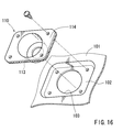
2005-125949 FIG. 16 , the user first inserts thecylindrical portion 113 of theinlet box 110 into ahole 103 provided in a recess of anouter panel 101 of the car. Aflange 114 provided around the opening of theinlet box 110 is then overlapped on theedge 102 around thehole 103 from the outside. Next, theflange 114 of theinlet box 110 is screwed to theedge 102 of thehole 103 from the outside of theouter panel 101. In this way theinlet box 110 is completely installed onto theouter panel 101. A lid (not shown) capable of closing the recess in theouter panel 101 is connected to theouter panel 101 through a hinge mechanism (not shown). - The
flange 114 on theinlet box 110 is screwed to theedge 102 of thehole 103 of theouter panel 101. Thus theinlet box 110 is easy to detach when the lid is opened and makes theinlet box 110 easy to steal. A theft preventative structure is desired. In addition, the head of the screw is visible when the lid is opened, so an improved appearance is also desired. - There is another possible way in which the
flange 114 of theinlet box 110 is mounted onto theedge 102 of thehole 103 of theouter panel 101 from the inside. Theinlet box 110, in general, is mounted on the side of theouter panel 101. For this reason, if a force should be applied to theinlet box 110 so as to push it outwardly at the time of screwing, theinlet box 110 could possibly fall from theouter panel 101 or shifted from the screwing position. It is thus desired to improve mounting theinlet box 110 from the inside onto theouter panel 101 with screws. - According to one aspect of the present invention, there is provided an inlet box mounting structure for a car which includes an outer panel of the car having a hole, an inlet box inserted in the hole, a flange provided around the opening of the inlet box, and an engaging claw provided on the outer peripheral surface of the inlet box. The flange is set onto the edge of the hole from the outside, and screwed to the edge of the hole of the outer panel from the inside. The engaging claw engages the edge of the hole of the outer panel from the inside when the flange is set on the edge of the hole. The engaging claw is capable of disengaging from the edge of the hole by a disengagement operation inside the outer panel.
- This may prevent the inlet box from falling or slipping out of place on the outer panel if a force is applied to press the inlet box outwardly when mounting the inlet box onto the outer panel. This may improve feasibility in mounting the inlet box with screws onto the outer panel. The improved feasibility may lead, for example, to an easier exchange of inlet boxes.
- In addition, the engaging claw of the inlet box is configured to disengage from the edge of the hole by a disengagement operation inside the outer panel. Therefore, the engaging claw does not prevent removal of the inlet box when exchanging inlet boxes.
-
-
FIG. 1 is a perspective view of a car having an inlet box mounting structure according to one embodiment. -
FIG. 2 is a perspective view of the assembly according to the embodiment as viewed from the front. -
FIG. 3 is a perspective view of the outer panel assembly as viewed from the inside of the car. -
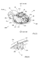
FIG. 4 is a perspective view of the back side of the inlet box as seen from the front above. -
FIG. 5 is a perspective view of the back side of the inlet box as viewed looking up at it from a rear position. -
FIG. 6 is an enlarged view of a part ofFIG. 4 indicated in the circle VI. -
FIG. 7 is an enlarged view of a part ofFIG. 5 indicated in the circle VII. -
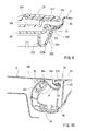
FIG. 8 is a horizontal cross-sectional view of the assembly and the mounting structure of the inlet box. -
FIG. 9 is an enlarged view of a part ofFIG. 8 indicated in the circle IX. -
FIG. 10 is a horizontal cross-sectional view of the hinge mechanism connecting the inlet box and the lid. -
FIG. 11 is a perspective view of the hinge pin of the hinge mechanism and the hinge hole in the lid. -
FIG. 12 is an enlarged cross-sectional view of the detent mechanism indicated in the circle XII inFIG. 10 . -
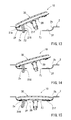
FIG. 13 is a side view of the assembly in the first stage to be set in the outer panel. -
FIG. 14 is a side view of the assembly in the second stage to be set in the outer panel. -
FIG. 15 is a side view of the assembly in the third stage to be set in the outer panel. -
FIG. 16 is a perspective view of a conventional inlet box mounting structure of a car. - Described below is an inlet box mounting structure of a car according to one embodiment of the present invention with reference to
FIGS. 1 to 13 . As shown inFIG. 8 , cars equipped with a rechargeable battery (such as electric vehicles (EV), plug-in hybrid electric vehicles (PHEV), etc.) have acharging connector 50 to which a connector of the power supply is connected when charging the battery. Thecharging connector 50 may be housed in aninlet box 20 made of resin. Theinlet box 20 is assembled to be a part of the inlet box assembly 10 (hereinafter simply referred to "assembly") made of resin. As shown inFIGS. 2 and8 , theassembly 10 is provided with alid 30 made of resin capable of opening and closing theopening 22 of theinlet box 20, and ahinge mechanism 40 rotatably connecting thelid 30 to theinlet box 20. In the following description, front and rear, right and left, and up and down are intended to respectively refer to the longitudinal, lateral, and vertical directions of the car. - As shown in
FIGS. 1 and3 , theinlet box 20 is mounted to a certain position on the side surface of the carouter panel 2. In the present embodiment, theinlet box 20 is mounted onto the outer panel on the right side of the car. Therefore, the left of theinlet box 20 is associated with the inside (front side) of the passenger compartment; and the right with the outside (back side). - As shown in
FIGS. 4 ,5 and8 , theinlet box 20 has abox body 21 housing the charging connector 50 (seeFIG. 8 ) and a bulgedportion 23 projecting laterally from thebox body 21. Thebox body 21 is formed in a generally cup-shape, which has an opening 22 (seeFIG. 8 ) and abottom 21b. The bulgedportion 23 is a generally angular bag-shape that is open toward thebox body 21. - A
circular flange 21f is formed around the opening 22 of the box body 21 (seeFIGS. 4 and5 ). Along the rim of theflange 21f is fixed aseal 21e made of rubber. Thebottom 21b of thebox body 21 has a bottom opening 21h through which a cable (not shown) is routed. This cable is connected to thecharging connector 50. - On the back surface of the
flange 21f, as shown inFIGS. 3 to 5 ,bolts 215 are fixed for mountinginlet box 20 onto theouter panel 2 of the car. Thebolts 215 project generally perpendicular to the back surface of theflange 21f. As shown inFIGS. 4 and5 , thebolts 215 are arranged on theflange 21f at intervals of about 90° in the circumferential direction, and two of them are provided for each of the upper and lower portions of thebox body 21. - As shown in
FIGS. 1 and3 , theouter panel 2 has acircular recess 2k configured to accommodate thelid 30. The bottom of therecess 2k has a generallycross-shaped hole 2j in which theinlet box 20 is to be fitted. As shown inFIG. 3 , theedge 2f around thehole 2j of the bottom of therecess 2k hasbolt holes 2b through which the respective fourbolts 215 on theflange 21f are to be inserted. The fourbolts 215 are inserted in the bolt holes 2b and nuts N are screwed on therespective bolts 215 from the inside of theouter panel 215. In this way theinlet box 20 can be mounted to the car. - As shown in
FIGS. 4 and6 , apositioning pin 216 is fixed on the back side of theflange 21f, at a position in the rear side of the upper front one of thebolts 215. As shown inFIG. 5 , on the back side of theflange 21f, anauxiliary positioning pin 217 is fixed in the front of the lower rear one of thebolts 215. Thepositioning pin 216 and theauxiliary positioning pin 217 are pins for positioning thebolt 215 with respect to thebolt holes 2b. - As shown in
FIG. 3 , apositioning hole 2x and anauxiliary positioning hole 2y are provided in theedge 2f around thehole 2j of theouter panel 2. Thepositioning pin 216 and the auxiliary positioning pin 217 (seeFIG. 5 ) are adapted to be passed through thepositioning hole 2x and theauxiliary positioning hole 2y, respectively. - The
positioning pin 216 is formed of such a length as to be inserted into thepositioning hole 2x from the beginning of inserting theinlet box 20 into thehole 2j. As will be described below, thepositioning pin 216 is curved along the insertion path of theinlet box 20. Theauxiliary positioning pin 217 is inserted into theauxiliary positioning hole 2y at the end of insertion of theinlet box 20, i.e., just before thebolt 215 on theflange 21f is inserted into the bolt holes 2b on theouter panel 2. - As shown in
FIGS. 5 and7 , an engagingclaw 220 may be fixed on the rear end of thebox body 21. The engagingclaw 220 is a claw which prevents theinlet box 20 from falling from theouter panel 2 while theflange 21f is set onto theedge 2f of thehole 2j of theouter panel 2 from the outside. Specifically, the engagingclaw 220 can engage theedge 2f of thehole 2j of theouter panel 2 from the inside of theouter panel 2. During such engagement, thebolts 215, thepositioning pin 216 and theauxiliary positioning pin 217 of theinlet box 20 reinserted in thebolt holes 2b, thepositioning hole 2x and theauxiliary positioning hole 2y of theouter panel 2, respectively. - As shown in
FIGS. 7 and9 , the engagingclaw 220 has aclaw body 224 and a claw support 222 (seeFIG. 9 ). Theclaw support 222 is of an arch shape having a generally U-shaped cross-section. It is open towards theflange 21f and has arear wall 222b. Theclaw body 224 is formed by cutting therear wall 222b whereby a U-shaped slit is formed. This construction allows theclaw body 224 to maintain integral construction connection to the top of the arch shape. - As shown in
FIG. 9 , theclaw body 224 is capable of being bent with resin elasticity inwardly and outwardly in the radial direction of thebox body 21. Theclaw body 224 may be supported in the portion near the top of the arch shape of theclaw support 222. While theinlet box 20 is inserted into thehole 2j in theouter panel 2, theclaw body 224 is deformed in accordance with its elasticity. Deformation can be viewed with reference to the double-chained line. If forced against its retentive properties, it rubs across theedge 2f around thehole 2j. On the distal end of theclaw body 224, i.e., the portion farthest from the support, anedge 225 is formed in parallel with theflange 21f. An inner portion of theedge 225 may be configured to engage theedge 2f of thehole 2j from the inside of theouter panel 2. As indicated by the double-chained line inFIG. 9 , theclaw body 224 can be bent inwardly against its elastic resistance in the radial direction of thebox body 21. Through manual operation one can detach theedge 225 engaged with theedge 2f. - As shown in
FIGS. 2 and8 , thelid 30 has a disc-shapedlid body 32 capable of closing theopening 22 while being disposed coaxially with theflange 21f. A generallyU-shaped lever 35 connects thelid body 32 to theinlet box 20 via ahinge mechanism 40. - The
lid body 32 has an outer diameter set generally equal to that of theflange 21f and thus can be housed within therecess 2k of theouter panel 2. As shown inFIG. 8 , thelid body 32 is formed of afront plate 32f and aback plate 32u coupled together. Acover 32c of the chargingconnector 50 is formed at the center of theback plate 32u. - The
lever 35 on thelid 30 is rotatably provided about the rotation axis of thehinge mechanism 40. The rotating end of thelever 35 on thelid 30 is connected to the front end of therear surface plate 32u of thelid body 32. As shown inFIG. 8 , thelever 35 on thelid 30 can be accommodated in the bulgedportion 23 of theinlet box 20. - The
hinge mechanism 40 is one which connects thelid 30 generally horizontally rotatably to theinlet box 20. As shown inFIG. 11 , thehinge mechanism 40 has ahinge pin 41 and alever 43 provided at the proximal end of thehinge pin 41. Thelever 43 is mounted such that it does not rotate with respect to thehinge pin 41. As shown inFIG. 4 , thehinge mechanism 40 has a coil spring 45 (biasing member) disposed between the bulgedportion 23 of theinlet box 20 and thelever 43. - As shown in
FIG. 11 , thehinge pin 41 has apin body 41u and acylindrical portion 430. Thepin body 41u has a proximal end integrated to thecylindrical portion 430. Thecylindrical portion 430 is provided with a larger-diametercylindrical portion 433 located closer to the base end of thepin body 41u and a smaller-diameter detent portion 435 located near the distal end. - As shown in
FIGS. 4 and5 , anupper bearing 23j and alower bearing 23k are fixed on the upper wall and the lower wall, respectively, on the front end of the bulgedportion 23 of theinlet box 20, in the outboard position. The larger-diametercylindrical portion 433 of thehinge pin 41 and the distal end of thepin body 41u are passed through each of theupper bearing 23j and thelower bearing 23k. - The
detent portion 435 has aridge 435t provided on its outer peripheral surface which extends in the axial direction. Theridge 435t is configured to have twoside surfaces FIG. 12 , they each extend along a radial line R from the rotation center O of thehinge pin 41. In other words, theridge 435t has a generally fan-shaped cross-section. - As shown in
FIG. 11 , thelever 43 is a generally gourd-shaped plate with two discs coupled together. One disc constituting thelever 43 is integrated into the larger-diametercylindrical portion 433 of thehinge pin 41. - The
lever 35 of thelid portion 30 has a proximal end provided with, as shown inFIGS. 10 and11 , a throughhole 35k in which thepin body 41u is fitted, and a detent hole (hinge hole) 35x in which thedetent portion 435 is fitted. Thedetent hole 35x is provided with agroove 35z in which theridge 435t is fitted in the axial direction. - The
groove 35z is configured to have twoside surfaces 351 and 352 (contact surface) that face each other in the circumferential direction. As viewed in cross-section shown inFIG. 12 , the twoside surfaces hinge pin 41. Oneside surface 351 of theridge 435t is in contact with oneside surface 435s of thegroove 35z, and theother side surface 352 of theridge 435t is in contact with theother side surface 435u of thegroove 35z. In this way, theridge 435t and thegroove 35z have side surfaces in contact with each other's side surfaces, and are thereby engaged together with respect to the circumferential direction. In particular, the side surfaces 435s and 435u of theridge 435t and the side surfaces 351 and 352 of thegroove 35z are provided perpendicular to the direction of the rotation. - As shown in
FIG. 4 the coil spring 45 (urging member) is mounted between thelever 43 of thehinge mechanism 40 and the bulgedportion 23 of theinlet box 20. Thecoil spring 45 is capable of imparting rotational force (biasing force) to thelid 30 in a direction to fully open and completely close theopening 22 of theinlet box 20. Since thehinge pin 41 and thelid 30 has the detent by fitting of theridge 435t andgroove 35z, the rotational force by thecoil spring 45 is transmitted from thelever 43 and thedetent portion 435 of thehinge pin 41, through theridge 435t and thegroove 35z, then to thelid 30. - As shown in
FIG. 8 , during construction of the assembly, thelever 35 on thelid 30 is first inserted through theopening 22 into the bulgedportion 23 of theinlet box 20. Next, the throughhole 35k and thedetent hole 35x, in thelever 35 of thelid 30, are held coaxially with thelower bearing 23k and theupper bearing 23j. Thelower bearing 23k and theupper bearing 23j are provided on the bulgedportion 23 of theinlet box 20. - The
hinge pin 41 is then inserted into theinlet box 20 from the side of theupper bearing 23j until thepin body 41u of thehinge pin 41 is fitted in the throughhole 35k in thelever 35 on thelid 30. Preferably, as shown inFIG. 5 , thehinge pin 41 is fitted into the distal end of thepin body 41u and is held in thelower bearing 23k on theinlet box 20. As shown inFIG. 12 , thedetent portion 435 of thehinge pin 41 is fitted in thedetent hole 35x in thelever 35 of thelid 30. Theridge 435t on thedetent portion 435 is fitted in thegroove 35z in thedetent hole 35x. Further, the larger-diametercylindrical portion 433 of thehinge pin 41 is held in theupper bearing 23j of theinlet box 20, as shown inFIG. 4 . Thelever 35 of thelid 30 and thehinge pin 41 thus become capable of rotating in theupper bearing 23j and thelower bearing 23k of theinlet box 20. - In order to mount the
assembly 10 onto theouter panel 2, the bulgedportion 23 of theinlet box 20 is first inserted into thehole 2j in theouter panel 2 while theassembly 10 is kept tilted. Next, as shown inFIG. 13 , the distal end of thepositioning pin 216 on theflange 21 f of theinlet box 20 is inserted into thepositioning hole 2x in theedge 2f of thehole 2j of theouter panel 2. Thepositioning pin 216 enters thepositioning hole 2x while theinlet box 20 goes into thehole 2j in theouter panel 2, as shown inFIG. 14 . During this procedure, theauxiliary positioning pin 217 on theflange 21f can be inserted into theauxiliary positioning hole 2y in theouter panel 2 to allow for positioning thebolts 215 on theflange 21f with respect to the bolt holes 2b on theouter panel 2. Thebolts 215 on theflange 21f are then inserted into thebolt holes 2b in theedge 2f of thehole 2j. In this way, theflange 21f and thelid body 32 of thelid 30 can be accommodated in acircular recess 2k in theouter panel 2 as shown inFIGS. 8 and15 . - Next, the
flange 21f is set on theedge 2f of thehole 2j of theouter panel 2. During this procedure, theclaw body 224 of the engagingclaw 220 on theinlet box 20 passes through thehole 2j. During this procedure, theclaw body 224 tends to rub across the edge of thehole 2j and bend radially inwardly against its own elastic strength (see the two-dot chain line inFIG. 9 ). When theclaw body 224 of the engagingclaw 220 has passed through thehole 2j, theedge 225 of theclaw body 224 springs radially outward due to its elasticity (see the solid line inFIG. 9 ) to engage with theedge 2f of thehole 2j from the inside of theouter panel 2. - Next, as shown in
FIG. 3 , the nut N is screwed from the inside of theouter panel 2 onto each of thebolts 215 on theflange 21f to affix theassembly 10 to theouter panel 2. Theedge 225 of theclaw body 224 of theinlet box 20 engages with theedge 2f of thehole 2j of theouter panel 2. In this way, even if a force is applied in such a direction as to push theinlet box 20 outward, theinlet box 20 will not fall or slip off theouter panel 2. - As described above, the mounting structure of the
inlet box 20 of a car includes: theouter panel 2 of the car having thehole 2j; theinlet box 20 inserted in thehole 2j; theflange 21f provided around theopening 22 of theinlet box 20; and the engagingclaw 220 provided on the outer peripheral surface of theinlet box 20. Theflange 21f is set onto theedge 2f of thehole 2j from the outside and screwed to theedge 2f of thehole 2j of theouter panel 2 from the inside. The engagingclaw 220 engages with theedge 2f of thehole 2j from the inside of theouter panel 2 when theflange 21f is set onto theedge 2f of thehole 2j. The engagingclaw 220 is capable of disengaging from theedge 2f of thehole 2j by a disengagement operation inside theouter panel 2. - If a force is applied to the
inlet box 20 to press it outwardly, this suppresses theinlet box 20 from falling or slipping off theouter panel 2 when screwed to theouter panel 2 to theinlet box 20. This may improve feasibility in attaching theinlet box 20 to theouter panel 2. The improved feasibility may lead, for example, to an easier exchange of theinlet box 20. - In addition, the engaging
claw 220 of theinlet box 20 can be disengaged from theedge 2f of thehole 2j by a disengaging operation inside theouter panel 2. The engagingclaw 220 thus does not prevent removal of theinlet box 20 when exchanging theinlet box 20 for another. - In addition, the mounting structure of the
inlet box 20 is provided with thepositioning hole 2x provided in theedge 2f of thehole 2j of theouter panel 2. It is also provided with apositioning pin 216 provided on theflange 21f on theinlet box 20. Thepositioning pin 216 is curved along its insertion path where theinlet box 20 is to be inserted into the hole in theouter panel 2. Thepositioning pin 216 is inserted into thepositioning hole 2x. - Inserting the
positioning pin 216 in theinlet box 20 into thepositioning hole 2x in theouter panel 2 allows an appropriate insertion path along which theinlet box 20 can be inserted into thehole 2j in theouter panel 2. Therefore, theinlet box 20 is easily set onto theouter panel 2 even in the situation where theinlet box 20 has a more complex configuration. In addition, that prevents scratching the surface of theouter panel 2. - In addition, the mounting structure of the
inlet box 20 is further provided with thelid 30 to open and close the opening of theinlet box 20. A hinge mechanism connects thelid 30 to theinlet box 20. The hinge mechanism includes: the detent hole (hinge hole) 35x provided on thelid 30; thehinge pin 41 inserted into thedetent hole 35x; theridge 435t and thegroove 35z disposed between thedetent hole 35x and thehinge pin 41. Theridge 435t and thegroove 35z are preferably fitted to each other so as to restrict the relative rotation of thelid 30 and thehinge pin 41; and the coil spring 45 (biasing member) biasing thehinge pin 41 to hold alid 30 at a certain position. Theridge 435t and thegroove 35z includes contact surfaces in contact with each other and perpendicular to the direction of the rotational force applied by thecoil spring 45. - Thus, when a rotational force by the
coil spring 45 is transmitted from thehinge pin 41 of thehinge mechanism 40 to thelid 30, radial sliding or play does not occur, i.e. the rotational force is efficiently transmitted between the side surfaces 351 and 352 of thegroove 35z and the side surfaces 435s and 435u of theridge 435t. Therefore, less wear will be caused in the fitting portion of thegroove 35z andridge 435t. - In addition, the mounting structure of the
inlet box 20 may have a charging connector provided in the inlet box. The charging connector is connected to a power source connector when charging the battery of the car. The mounting structure of theinlet box 20 may thus be applied to automobiles, such as electric vehicles and plug-in hybrid electric vehicles, to achieve the effects stated above. - While the embodiments of invention have been described with reference to specific configurations, it will be apparent to those skilled in the art that many alternatives, modifications and variations may be made without departing from the scope of the present invention. Accordingly, embodiments of the present invention are intended to embrace all such alternatives, modifications and variations that may fall within the spirit and scope of the appended claims. For example, embodiments of the present invention should not be limited to the representative configurations, but may be modified, for example, as described below.
- Two or more
engaging claws 220 may also be provided, and these engaging claws may be arranged, for example, along the circumferential direction of theinlet box 20. There may optionally be provided a plurality ofhinge pin 41 and groove (hinge hole) 35z sets in different embodiments. The inlet box may be not only theinlet box 20 with a chargingconnector 50 but also a fuel inlet box having a fuel supply port.
Claims (4)
- An inlet box mounting structure of a car, comprising:an outer panel of a car having a hole;an inlet box inserted into the hole;a flange provided around the opening of the inlet box,
wherein the flange is set onto an edge of the hole from the outside and screwed to the edge of the hole of the outer panel from the inside; andan engaging claw provided on an outer peripheral surface of the inlet box,
wherein the engaging claw engages the edge of the hole of the outer panel from the inside when the flange is set on the edge of the hole, and
wherein the engaging claw is capable of disengaging from the edge of the hole by a disengagement operation of the outer panel. - An inlet box mounting structure of a car according to claim 1, further comprising:a positioning hole provided on the edge of the hole of the outer panel,a positioning pin provided in the flange of the inlet box,
wherein the positioning pin is curved along the insertion path of the inlet box into the hole in the outer panel and the positioning pin is inserted into the positioning hole. - An inlet box mounting structure of a car according to claim 1 or 2, further comprising:a lid to open and close an opening of the inlet box; anda hinge mechanism connecting the lid to the inlet box,wherein the hinge mechanism comprises:a hinge hole provided in the lid;a hinge pin inserted in the hinge hole;a ridge and a groove provided between the hinge pin and the hinge hole and fitted to each other so as to restrict the relative rotation of the lid and the hinge pin; anda biasing member biasing the hinge pin to hold the lid at a certain position;wherein the ridge and the groove comprise a contact surface between each other and perpendicular to the direction of the rotational force applied by the biasing member.
- An inlet box mounting structure of a car according to any one of claims 1 to 3, wherein a charging connector is provided in the inlet box, which is to be connected to a power source connector when charging the battery of the car.
Applications Claiming Priority (2)
| Application Number | Priority Date | Filing Date | Title |
|---|---|---|---|
| JP2011109342A JP5636566B2 (en) | 2011-05-16 | 2011-05-16 | Vehicle inlet box mounting structure |
| PCT/JP2012/061873 WO2012157489A1 (en) | 2011-05-16 | 2012-05-09 | Structure for mounting vehicle inlet box |
Publications (3)
| Publication Number | Publication Date |
|---|---|
| EP2581250A1 true EP2581250A1 (en) | 2013-04-17 |
| EP2581250A4 EP2581250A4 (en) | 2014-05-14 |
| EP2581250B1 EP2581250B1 (en) | 2016-08-03 |
Family
ID=47176819
Family Applications (1)
| Application Number | Title | Priority Date | Filing Date |
|---|---|---|---|
| EP12785265.5A Not-in-force EP2581250B1 (en) | 2011-05-16 | 2012-05-09 | Structure for mounting vehicle inlet box |
Country Status (5)
| Country | Link |
|---|---|
| US (1) | US9083163B2 (en) |
| EP (1) | EP2581250B1 (en) |
| JP (1) | JP5636566B2 (en) |
| CN (1) | CN103025555B (en) |
| WO (1) | WO2012157489A1 (en) |
Cited By (4)
| Publication number | Priority date | Publication date | Assignee | Title |
|---|---|---|---|---|
| WO2015067631A1 (en) * | 2013-11-07 | 2015-05-14 | Volkswagen Aktiengesellschaft | Flap module |
| FR3027851A1 (en) * | 2014-10-31 | 2016-05-06 | Porsche Ag | CHARGING DEVICE FOR A VEHICLE WITH ELECTRIC DRIVE |
| FR3087160A1 (en) * | 2018-10-10 | 2020-04-17 | Renault S.A.S | SYSTEM FOR MOUNTING A FUEL HATCH BOWL |
| EP4155108A1 (en) * | 2021-09-07 | 2023-03-29 | Toyota Jidosha Kabushiki Kaisha | Fuel inlet structure of vehicle |
Families Citing this family (24)
| Publication number | Priority date | Publication date | Assignee | Title |
|---|---|---|---|---|
| JP5920146B2 (en) * | 2012-09-27 | 2016-05-18 | 豊田合成株式会社 | Fuel inlet box seal structure |
| US20160280061A1 (en) * | 2013-11-19 | 2016-09-29 | Illinois Tool Works Inc. | A fuel filler assembly for a vehicle |
| WO2015079960A1 (en) * | 2013-11-28 | 2015-06-04 | 八千代工業株式会社 | Seal structure for fuel tank |
| JP5952324B2 (en) | 2014-02-21 | 2016-07-13 | トヨタ自動車株式会社 | Vehicle charging section |
| US10179518B2 (en) | 2014-11-14 | 2019-01-15 | Ricky Jay Henderson | Power docking port system with tetrahedral charging probe |
| CN105172580A (en) * | 2015-09-25 | 2015-12-23 | 重庆博荣拓尔科技有限公司 | Anti-looseness oil tank |
| CN105172581A (en) * | 2015-09-25 | 2015-12-23 | 重庆博荣拓尔科技有限公司 | Fuel tank cap |
| CN105172582A (en) * | 2015-09-25 | 2015-12-23 | 重庆博荣拓尔科技有限公司 | Anti-slip oil tank cap |
| US20170101022A1 (en) * | 2015-10-12 | 2017-04-13 | Revitalize Charging Solutions, Inc. | Apparatus and method for dual automobile electric charger |
| IT201600104772A1 (en) * | 2016-10-18 | 2018-04-18 | Cebi Italy Spa | SYSTEM FOR THE CLOSING OF A DOOR OF THE FUEL TANK. |
| CN107042769A (en) * | 2017-03-16 | 2017-08-15 | 重庆国翰能源发展有限公司 | A kind of household electricity electrical automobile identification and charging system |
| JP2018192925A (en) * | 2017-05-18 | 2018-12-06 | ダイキョーニシカワ株式会社 | Fuel case assembly |
| JP7003779B2 (en) * | 2018-03-23 | 2022-01-21 | トヨタ自動車株式会社 | Vehicle refueling section structure |
| JP7587344B2 (en) | 2018-04-12 | 2024-11-20 | レーヴェンシュタイン メディカル テクノロジー エス.アー. | System for transmitting data |
| DE102018125209A1 (en) * | 2018-10-11 | 2020-04-16 | Bayerische Motoren Werke Aktiengesellschaft | Tank or tailgate assembly |
| JP7233307B2 (en) * | 2019-05-31 | 2023-03-06 | ダイキョーニシカワ株式会社 | Mounting structure of the fuel lid device |
| DE102019119091B4 (en) * | 2019-07-15 | 2022-02-10 | Illinois Tool Works Inc. | LOADER OR TANK HOUSING AND METHOD OF MANUFACTURE THEREOF |
| JP7489263B2 (en) * | 2020-08-20 | 2024-05-23 | 西川ゴム工業株式会社 | Seal member mounting structure |
| CN116783090A (en) * | 2021-01-27 | 2023-09-19 | 浙江智马达智能科技有限公司 | A car charging port cover structure and car |
| JP7649097B2 (en) * | 2021-01-28 | 2025-03-19 | 株式会社Fts | Lid mounting structure |
| JP7649098B2 (en) * | 2021-01-28 | 2025-03-19 | 株式会社Fts | Lid mounting structure |
| US11794821B2 (en) * | 2022-02-14 | 2023-10-24 | Honda Motor Co., Ltd. | Vehicle fender assembly including a charge port assembly |
| JP7597064B2 (en) * | 2022-03-22 | 2024-12-10 | トヨタ自動車株式会社 | Charging inlet device |
| JP7838453B2 (en) | 2022-11-10 | 2026-04-01 | 豊田合成株式会社 | Lid opening and closing device |
Family Cites Families (24)
| Publication number | Priority date | Publication date | Assignee | Title |
|---|---|---|---|---|
| JPS6211209Y2 (en) | 1981-03-11 | 1987-03-17 | ||
| JPS58139328U (en) * | 1982-03-17 | 1983-09-19 | スズキ株式会社 | car fuel filler |
| US5090760A (en) * | 1990-01-29 | 1992-02-25 | Wheeler Basil W | Break-away gas fill guard |
| JP2516895Y2 (en) | 1991-06-14 | 1996-11-13 | ダイハツ工業株式会社 | Fuel inlet box seal structure |
| JPH0613924U (en) | 1992-07-29 | 1994-02-22 | トヨタ車体株式会社 | Filler structure |
| JPH0671246U (en) | 1993-03-23 | 1994-10-04 | 日野自動車工業株式会社 | Vehicle fuel inlet device |
| US5906406A (en) * | 1997-06-25 | 1999-05-25 | General Motors Corporation | Fuel filler pocket assembly |
| JP3680503B2 (en) | 1997-07-18 | 2005-08-10 | スズキ株式会社 | Fuel lid mounting structure |
| DE10157395B4 (en) * | 2001-11-23 | 2019-08-01 | Volkswagen Ag | Insert pot for a tank flap module of a vehicle, especially a motor vehicle |
| DE20305291U1 (en) | 2003-04-01 | 2003-06-18 | Dr. Schneider Engineering GmbH, 96317 Kronach | Swivel bearing for a flap, in particular for the flap in front of a tank cap in a motor vehicle |
| DE20311149U1 (en) | 2003-07-18 | 2003-10-16 | Dr. Schneider Engineering GmbH, 96317 Kronach | Tank recess made of plastic |
| JP4088239B2 (en) | 2003-10-24 | 2008-05-21 | 本田技研工業株式会社 | Fuel adapter structure |
| JP4406411B2 (en) * | 2006-03-31 | 2010-01-27 | 本田技研工業株式会社 | Fuel lid structure |
| KR100844672B1 (en) * | 2006-11-13 | 2008-07-07 | 기아자동차주식회사 | Housing for fuel door mounting of vehicle |
| JP5191813B2 (en) * | 2007-07-26 | 2013-05-08 | 株式会社ニフコ | Fixing device, fixing member fixing structure, fixing member fixing method, and fixing release method |
| JP4367559B2 (en) | 2007-08-10 | 2009-11-18 | トヨタ自動車株式会社 | vehicle |
| JP2009061974A (en) * | 2007-09-07 | 2009-03-26 | Honda Motor Co Ltd | Fuel lid structure |
| DE102008047464A1 (en) | 2008-09-17 | 2010-04-15 | Dr.Ing.H.C.F.Porsche Aktiengesellschaft | Tank flap module for motor vehicle, has damping medium provided with stop cushion lying inside and arranged in hinge arm of hinge, where stop cushion is aligned to tank filler tray with front surface of stop wall |
| FR2936448B1 (en) * | 2008-09-29 | 2011-06-17 | Peugeot Citroen Automobiles Sa | DEVICE FOR PRECISIONALLY FITTING A FUEL HATCH IN AN OPENING MADE IN THE SHEET OF THE BOX OF A MOTOR VEHICLE |
| JP2010203208A (en) * | 2009-03-06 | 2010-09-16 | Toyota Auto Body Co Ltd | Lid member opening and closing structure for vehicle |
| JP5417995B2 (en) | 2009-06-02 | 2014-02-19 | 三菱自動車工業株式会社 | Lid device |
| JP5198361B2 (en) * | 2009-06-04 | 2013-05-15 | トヨタ自動車株式会社 | Retainer structure |
| JP5360480B2 (en) * | 2009-06-22 | 2013-12-04 | 株式会社ニフコ | Fastener |
| WO2010151635A2 (en) * | 2009-06-24 | 2010-12-29 | Huawei Technologies Co., Ltd. | Method and apparatus for electric powered vehicle recharging safety |
-
2011
- 2011-05-16 JP JP2011109342A patent/JP5636566B2/en active Active
-
2012
- 2012-05-09 US US13/808,560 patent/US9083163B2/en active Active
- 2012-05-09 CN CN201280001909.8A patent/CN103025555B/en not_active Expired - Fee Related
- 2012-05-09 WO PCT/JP2012/061873 patent/WO2012157489A1/en not_active Ceased
- 2012-05-09 EP EP12785265.5A patent/EP2581250B1/en not_active Not-in-force
Cited By (5)
| Publication number | Priority date | Publication date | Assignee | Title |
|---|---|---|---|---|
| WO2015067631A1 (en) * | 2013-11-07 | 2015-05-14 | Volkswagen Aktiengesellschaft | Flap module |
| FR3027851A1 (en) * | 2014-10-31 | 2016-05-06 | Porsche Ag | CHARGING DEVICE FOR A VEHICLE WITH ELECTRIC DRIVE |
| US10322635B2 (en) | 2014-10-31 | 2019-06-18 | Dr. Ing. H.C. F. Porsche Aktiengesellschaft | Charging apparatus for a vehicle that can be driven electrically |
| FR3087160A1 (en) * | 2018-10-10 | 2020-04-17 | Renault S.A.S | SYSTEM FOR MOUNTING A FUEL HATCH BOWL |
| EP4155108A1 (en) * | 2021-09-07 | 2023-03-29 | Toyota Jidosha Kabushiki Kaisha | Fuel inlet structure of vehicle |
Also Published As
| Publication number | Publication date |
|---|---|
| EP2581250A4 (en) | 2014-05-14 |
| CN103025555A (en) | 2013-04-03 |
| US9083163B2 (en) | 2015-07-14 |
| US20140060920A1 (en) | 2014-03-06 |
| EP2581250B1 (en) | 2016-08-03 |
| JP2012240443A (en) | 2012-12-10 |
| CN103025555B (en) | 2015-08-26 |
| JP5636566B2 (en) | 2014-12-10 |
| WO2012157489A1 (en) | 2012-11-22 |
Similar Documents
| Publication | Publication Date | Title |
|---|---|---|
| EP2581250B1 (en) | Structure for mounting vehicle inlet box | |
| JP5609725B2 (en) | Wire holding member | |
| JP5645077B2 (en) | Charging connector | |
| US10358169B2 (en) | Coverless battery assembly for electrified vehicle | |
| US8671604B2 (en) | Marking carrier for marking a floating caliper brake | |
| JP6215519B2 (en) | Charging inlet device | |
| CN105673653B (en) | Locking device | |
| US20150258925A1 (en) | Device for assembling rear seat back assembly | |
| JP2008290566A (en) | Sun visor holder | |
| JP5741196B2 (en) | Charging connector mounting structure | |
| US9847610B2 (en) | Electric vehicle service disconnect position indicator | |
| EP1683657B1 (en) | Tyre monitoring unit for a vehicle | |
| CN107650581A (en) | Vehicle bridge component with half shaft subassemblies | |
| US9975440B1 (en) | Charge port covering assembly and method | |
| CN100458231C (en) | Drive plate assembly structure for torque converter | |
| US20240053174A1 (en) | Bracket assembly | |
| JP4836721B2 (en) | Electric vehicle | |
| JP2010106438A (en) | Lid locking device for vehicle | |
| JP5798062B2 (en) | Power receiving device | |
| JP5786683B2 (en) | Charging lid structure for vehicles | |
| JP2013021791A (en) | Grommet | |
| JP2006010000A (en) | tightening structure | |
| KR102947502B1 (en) | Emergency release cable opening and closing device of inlet | |
| JP3963312B2 (en) | Storage box for automobile and its mounting method | |
| CN222645918U (en) | Vehicle with a vehicle body having a vehicle body support |
Legal Events
| Date | Code | Title | Description |
|---|---|---|---|
| PUAI | Public reference made under article 153(3) epc to a published international application that has entered the european phase |
Free format text: ORIGINAL CODE: 0009012 |
|
| 17P | Request for examination filed |
Effective date: 20130103 |
|
| AK | Designated contracting states |
Kind code of ref document: A1 Designated state(s): AL AT BE BG CH CY CZ DE DK EE ES FI FR GB GR HR HU IE IS IT LI LT LU LV MC MK MT NL NO PL PT RO RS SE SI SK SM TR |
|
| RIN1 | Information on inventor provided before grant (corrected) |
Inventor name: TAMAOKI, TERUAKI Inventor name: IKUTA, HIROSHIGE Inventor name: MATSUDA, YASUHIRO |
|
| A4 | Supplementary search report drawn up and despatched |
Effective date: 20140410 |
|
| RIC1 | Information provided on ipc code assigned before grant |
Ipc: E06B 7/00 20060101ALI20140404BHEP Ipc: B60L 11/18 20060101ALI20140404BHEP Ipc: B60K 15/05 20060101ALI20140404BHEP Ipc: B60K 1/04 20060101AFI20140404BHEP Ipc: H02G 3/08 20060101ALI20140404BHEP Ipc: B60K 6/22 20071001ALI20140404BHEP Ipc: B60J 5/00 20060101ALI20140404BHEP Ipc: B60K 15/04 20060101ALI20140404BHEP |
|
| DAX | Request for extension of the european patent (deleted) | ||
| GRAP | Despatch of communication of intention to grant a patent |
Free format text: ORIGINAL CODE: EPIDOSNIGR1 |
|
| INTG | Intention to grant announced |
Effective date: 20160322 |
|
| GRAS | Grant fee paid |
Free format text: ORIGINAL CODE: EPIDOSNIGR3 |
|
| GRAA | (expected) grant |
Free format text: ORIGINAL CODE: 0009210 |
|
| AK | Designated contracting states |
Kind code of ref document: B1 Designated state(s): AL AT BE BG CH CY CZ DE DK EE ES FI FR GB GR HR HU IE IS IT LI LT LU LV MC MK MT NL NO PL PT RO RS SE SI SK SM TR |
|
| REG | Reference to a national code |
Ref country code: GB Ref legal event code: FG4D |
|
| REG | Reference to a national code |
Ref country code: CH Ref legal event code: EP Ref country code: AT Ref legal event code: REF Ref document number: 817091 Country of ref document: AT Kind code of ref document: T Effective date: 20160815 |
|
| REG | Reference to a national code |
Ref country code: IE Ref legal event code: FG4D |
|
| REG | Reference to a national code |
Ref country code: DE Ref legal event code: R096 Ref document number: 602012021262 Country of ref document: DE |
|
| REG | Reference to a national code |
Ref country code: NL Ref legal event code: MP Effective date: 20160803 |
|
| REG | Reference to a national code |
Ref country code: LT Ref legal event code: MG4D |
|
| REG | Reference to a national code |
Ref country code: AT Ref legal event code: MK05 Ref document number: 817091 Country of ref document: AT Kind code of ref document: T Effective date: 20160803 |
|
| PG25 | Lapsed in a contracting state [announced via postgrant information from national office to epo] |
Ref country code: NO Free format text: LAPSE BECAUSE OF FAILURE TO SUBMIT A TRANSLATION OF THE DESCRIPTION OR TO PAY THE FEE WITHIN THE PRESCRIBED TIME-LIMIT Effective date: 20161103 Ref country code: FI Free format text: LAPSE BECAUSE OF FAILURE TO SUBMIT A TRANSLATION OF THE DESCRIPTION OR TO PAY THE FEE WITHIN THE PRESCRIBED TIME-LIMIT Effective date: 20160803 Ref country code: NL Free format text: LAPSE BECAUSE OF FAILURE TO SUBMIT A TRANSLATION OF THE DESCRIPTION OR TO PAY THE FEE WITHIN THE PRESCRIBED TIME-LIMIT Effective date: 20160803 Ref country code: RS Free format text: LAPSE BECAUSE OF FAILURE TO SUBMIT A TRANSLATION OF THE DESCRIPTION OR TO PAY THE FEE WITHIN THE PRESCRIBED TIME-LIMIT Effective date: 20160803 Ref country code: LT Free format text: LAPSE BECAUSE OF FAILURE TO SUBMIT A TRANSLATION OF THE DESCRIPTION OR TO PAY THE FEE WITHIN THE PRESCRIBED TIME-LIMIT Effective date: 20160803 Ref country code: IS Free format text: LAPSE BECAUSE OF FAILURE TO SUBMIT A TRANSLATION OF THE DESCRIPTION OR TO PAY THE FEE WITHIN THE PRESCRIBED TIME-LIMIT Effective date: 20161203 Ref country code: IT Free format text: LAPSE BECAUSE OF FAILURE TO SUBMIT A TRANSLATION OF THE DESCRIPTION OR TO PAY THE FEE WITHIN THE PRESCRIBED TIME-LIMIT Effective date: 20160803 Ref country code: HR Free format text: LAPSE BECAUSE OF FAILURE TO SUBMIT A TRANSLATION OF THE DESCRIPTION OR TO PAY THE FEE WITHIN THE PRESCRIBED TIME-LIMIT Effective date: 20160803 |
|
| PG25 | Lapsed in a contracting state [announced via postgrant information from national office to epo] |
Ref country code: LV Free format text: LAPSE BECAUSE OF FAILURE TO SUBMIT A TRANSLATION OF THE DESCRIPTION OR TO PAY THE FEE WITHIN THE PRESCRIBED TIME-LIMIT Effective date: 20160803 Ref country code: GR Free format text: LAPSE BECAUSE OF FAILURE TO SUBMIT A TRANSLATION OF THE DESCRIPTION OR TO PAY THE FEE WITHIN THE PRESCRIBED TIME-LIMIT Effective date: 20161104 Ref country code: ES Free format text: LAPSE BECAUSE OF FAILURE TO SUBMIT A TRANSLATION OF THE DESCRIPTION OR TO PAY THE FEE WITHIN THE PRESCRIBED TIME-LIMIT Effective date: 20160803 Ref country code: AT Free format text: LAPSE BECAUSE OF FAILURE TO SUBMIT A TRANSLATION OF THE DESCRIPTION OR TO PAY THE FEE WITHIN THE PRESCRIBED TIME-LIMIT Effective date: 20160803 Ref country code: PT Free format text: LAPSE BECAUSE OF FAILURE TO SUBMIT A TRANSLATION OF THE DESCRIPTION OR TO PAY THE FEE WITHIN THE PRESCRIBED TIME-LIMIT Effective date: 20161205 Ref country code: PL Free format text: LAPSE BECAUSE OF FAILURE TO SUBMIT A TRANSLATION OF THE DESCRIPTION OR TO PAY THE FEE WITHIN THE PRESCRIBED TIME-LIMIT Effective date: 20160803 Ref country code: SE Free format text: LAPSE BECAUSE OF FAILURE TO SUBMIT A TRANSLATION OF THE DESCRIPTION OR TO PAY THE FEE WITHIN THE PRESCRIBED TIME-LIMIT Effective date: 20160803 |
|
| PG25 | Lapsed in a contracting state [announced via postgrant information from national office to epo] |
Ref country code: EE Free format text: LAPSE BECAUSE OF FAILURE TO SUBMIT A TRANSLATION OF THE DESCRIPTION OR TO PAY THE FEE WITHIN THE PRESCRIBED TIME-LIMIT Effective date: 20160803 Ref country code: RO Free format text: LAPSE BECAUSE OF FAILURE TO SUBMIT A TRANSLATION OF THE DESCRIPTION OR TO PAY THE FEE WITHIN THE PRESCRIBED TIME-LIMIT Effective date: 20160803 |
|
| REG | Reference to a national code |
Ref country code: DE Ref legal event code: R097 Ref document number: 602012021262 Country of ref document: DE |
|
| REG | Reference to a national code |
Ref country code: FR Ref legal event code: PLFP Year of fee payment: 6 |
|
| PG25 | Lapsed in a contracting state [announced via postgrant information from national office to epo] |
Ref country code: CZ Free format text: LAPSE BECAUSE OF FAILURE TO SUBMIT A TRANSLATION OF THE DESCRIPTION OR TO PAY THE FEE WITHIN THE PRESCRIBED TIME-LIMIT Effective date: 20160803 Ref country code: DK Free format text: LAPSE BECAUSE OF FAILURE TO SUBMIT A TRANSLATION OF THE DESCRIPTION OR TO PAY THE FEE WITHIN THE PRESCRIBED TIME-LIMIT Effective date: 20160803 Ref country code: BG Free format text: LAPSE BECAUSE OF FAILURE TO SUBMIT A TRANSLATION OF THE DESCRIPTION OR TO PAY THE FEE WITHIN THE PRESCRIBED TIME-LIMIT Effective date: 20161103 Ref country code: SK Free format text: LAPSE BECAUSE OF FAILURE TO SUBMIT A TRANSLATION OF THE DESCRIPTION OR TO PAY THE FEE WITHIN THE PRESCRIBED TIME-LIMIT Effective date: 20160803 Ref country code: BE Free format text: LAPSE BECAUSE OF FAILURE TO SUBMIT A TRANSLATION OF THE DESCRIPTION OR TO PAY THE FEE WITHIN THE PRESCRIBED TIME-LIMIT Effective date: 20160803 Ref country code: SM Free format text: LAPSE BECAUSE OF FAILURE TO SUBMIT A TRANSLATION OF THE DESCRIPTION OR TO PAY THE FEE WITHIN THE PRESCRIBED TIME-LIMIT Effective date: 20160803 |
|
| PLBE | No opposition filed within time limit |
Free format text: ORIGINAL CODE: 0009261 |
|
| STAA | Information on the status of an ep patent application or granted ep patent |
Free format text: STATUS: NO OPPOSITION FILED WITHIN TIME LIMIT |
|
| 26N | No opposition filed |
Effective date: 20170504 |
|
| PG25 | Lapsed in a contracting state [announced via postgrant information from national office to epo] |
Ref country code: SI Free format text: LAPSE BECAUSE OF FAILURE TO SUBMIT A TRANSLATION OF THE DESCRIPTION OR TO PAY THE FEE WITHIN THE PRESCRIBED TIME-LIMIT Effective date: 20160803 Ref country code: LU Free format text: LAPSE BECAUSE OF NON-PAYMENT OF DUE FEES Effective date: 20170531 |
|
| REG | Reference to a national code |
Ref country code: CH Ref legal event code: PL |
|
| GBPC | Gb: european patent ceased through non-payment of renewal fee |
Effective date: 20170509 |
|
| PG25 | Lapsed in a contracting state [announced via postgrant information from national office to epo] |
Ref country code: MC Free format text: LAPSE BECAUSE OF FAILURE TO SUBMIT A TRANSLATION OF THE DESCRIPTION OR TO PAY THE FEE WITHIN THE PRESCRIBED TIME-LIMIT Effective date: 20160803 |
|
| REG | Reference to a national code |
Ref country code: IE Ref legal event code: MM4A |
|
| PG25 | Lapsed in a contracting state [announced via postgrant information from national office to epo] |
Ref country code: LI Free format text: LAPSE BECAUSE OF NON-PAYMENT OF DUE FEES Effective date: 20170531 Ref country code: CH Free format text: LAPSE BECAUSE OF NON-PAYMENT OF DUE FEES Effective date: 20170531 |
|
| PG25 | Lapsed in a contracting state [announced via postgrant information from national office to epo] |
Ref country code: LU Free format text: LAPSE BECAUSE OF NON-PAYMENT OF DUE FEES Effective date: 20170509 |
|
| PG25 | Lapsed in a contracting state [announced via postgrant information from national office to epo] |
Ref country code: IE Free format text: LAPSE BECAUSE OF NON-PAYMENT OF DUE FEES Effective date: 20170509 Ref country code: GB Free format text: LAPSE BECAUSE OF NON-PAYMENT OF DUE FEES Effective date: 20170509 |
|
| REG | Reference to a national code |
Ref country code: FR Ref legal event code: PLFP Year of fee payment: 7 |
|
| PG25 | Lapsed in a contracting state [announced via postgrant information from national office to epo] |
Ref country code: MT Free format text: LAPSE BECAUSE OF NON-PAYMENT OF DUE FEES Effective date: 20170509 |
|
| PG25 | Lapsed in a contracting state [announced via postgrant information from national office to epo] |
Ref country code: AL Free format text: LAPSE BECAUSE OF FAILURE TO SUBMIT A TRANSLATION OF THE DESCRIPTION OR TO PAY THE FEE WITHIN THE PRESCRIBED TIME-LIMIT Effective date: 20160803 |
|
| RIC2 | Information provided on ipc code assigned after grant |
Ipc: B60K 6/22 20071001ALI20140404BHEP Ipc: B60J 5/00 20060101ALI20140404BHEP Ipc: B60K 15/04 20060101ALI20140404BHEP Ipc: B60L 11/18 20060101ALI20140404BHEP Ipc: H02G 3/08 20060101ALI20140404BHEP Ipc: B60K 1/04 20190101AFI20140404BHEP Ipc: B60K 15/05 20060101ALI20140404BHEP Ipc: E06B 7/00 20060101ALI20140404BHEP |
|
| PG25 | Lapsed in a contracting state [announced via postgrant information from national office to epo] |
Ref country code: HU Free format text: LAPSE BECAUSE OF FAILURE TO SUBMIT A TRANSLATION OF THE DESCRIPTION OR TO PAY THE FEE WITHIN THE PRESCRIBED TIME-LIMIT; INVALID AB INITIO Effective date: 20120509 |
|
| PG25 | Lapsed in a contracting state [announced via postgrant information from national office to epo] |
Ref country code: CY Free format text: LAPSE BECAUSE OF NON-PAYMENT OF DUE FEES Effective date: 20160803 |
|
| PG25 | Lapsed in a contracting state [announced via postgrant information from national office to epo] |
Ref country code: MK Free format text: LAPSE BECAUSE OF FAILURE TO SUBMIT A TRANSLATION OF THE DESCRIPTION OR TO PAY THE FEE WITHIN THE PRESCRIBED TIME-LIMIT Effective date: 20160803 |
|
| PG25 | Lapsed in a contracting state [announced via postgrant information from national office to epo] |
Ref country code: TR Free format text: LAPSE BECAUSE OF FAILURE TO SUBMIT A TRANSLATION OF THE DESCRIPTION OR TO PAY THE FEE WITHIN THE PRESCRIBED TIME-LIMIT Effective date: 20160803 |
|
| PGFP | Annual fee paid to national office [announced via postgrant information from national office to epo] |
Ref country code: DE Payment date: 20200428 Year of fee payment: 9 Ref country code: FR Payment date: 20200414 Year of fee payment: 9 |
|
| REG | Reference to a national code |
Ref country code: DE Ref legal event code: R119 Ref document number: 602012021262 Country of ref document: DE |
|
| PG25 | Lapsed in a contracting state [announced via postgrant information from national office to epo] |
Ref country code: DE Free format text: LAPSE BECAUSE OF NON-PAYMENT OF DUE FEES Effective date: 20211201 |
|
| PG25 | Lapsed in a contracting state [announced via postgrant information from national office to epo] |
Ref country code: FR Free format text: LAPSE BECAUSE OF NON-PAYMENT OF DUE FEES Effective date: 20210531 |