JP4088239B2 - Fuel adapter structure - Google Patents
Fuel adapter structure Download PDFInfo
- Publication number
- JP4088239B2 JP4088239B2 JP2003364320A JP2003364320A JP4088239B2 JP 4088239 B2 JP4088239 B2 JP 4088239B2 JP 2003364320 A JP2003364320 A JP 2003364320A JP 2003364320 A JP2003364320 A JP 2003364320A JP 4088239 B2 JP4088239 B2 JP 4088239B2
- Authority
- JP
- Japan
- Prior art keywords
- vehicle body
- fuel
- opening
- locking claw
- fuel adapter
- Prior art date
- Legal status (The legal status is an assumption and is not a legal conclusion. Google has not performed a legal analysis and makes no representation as to the accuracy of the status listed.)
- Expired - Fee Related
Links
Images


Description
本発明は、自動車の車体に形成した給油用の開口部へ取り付けるフューエルアダプタ構造に関し、特に、簡単な構造で、かつ、小スペースで開口部への取り付けを可能にするフューエルアダプタ構造に関する。 The present invention relates to a fuel adapter structure that is attached to an opening portion for refueling formed in a vehicle body of an automobile, and more particularly, to a fuel adapter structure that can be attached to an opening portion with a simple structure and in a small space.
従来、自動車の給油口におけるフューエルアダプタの取付構造として、車体とフューエルパイプとの間に介在されるフューエルアダプタの外向きフランジを、リヤフェンダ等の車体の一部に円形にくり抜いた開口部にネジ止めすることによって取り付けるようにした技術がある(例えば、特許文献1参照)。このフューエルアダプタは、フューエルパイプ本体に一体成形されたネック部の外向きに広がるフランジを車体の給油用開口部の周縁部に係止させ、ネジで固定して車体に取り付けるように構成されている。 Conventionally, as a fuel adapter mounting structure at the fuel filler opening of an automobile, the outward flange of the fuel adapter that is interposed between the vehicle body and the fuel pipe is screwed into an opening formed in a part of the vehicle body such as a rear fender in a circular shape. There is a technique in which attachment is performed by doing (see, for example, Patent Document 1). This fuel adapter is configured such that a flange extending outwardly of a neck portion integrally formed with a fuel pipe main body is engaged with a peripheral portion of an oil supply opening of a vehicle body and fixed with a screw to be attached to the vehicle body. .
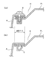
このように、従来のフューエルアダプタの取付構造は、ネジやクリップによってフューエルアダプタを車体パネルの開口部に取り付ける構造が採られていた。例えば、図6に示す構造では、フューエルアダプタAは、アウタパネルP1の一部に形成された開口部Oに取り付けられている。車体の開口部Oには、アウタパネルP1の車体表面から段差をもって室内側に略矩形状の窪み部Hが形成されている。この窪み部Hに形成された開口部OにフューエルアダプタAが嵌め込まれて、そのフューエルアダプタAのフランジF1を開口部Oの周縁部に係止させてビス止めにより固着している。 Thus, the conventional fuel adapter mounting structure employs a structure in which the fuel adapter is mounted to the opening of the vehicle body panel with screws or clips. For example, in the structure shown in FIG. 6, the fuel adapter A is attached to an opening O formed in a part of the outer panel P 1 . The body of the opening O, a substantially rectangular recess H on the indoor side with a step from the body surface of the outer panel P 1 is formed. The fuel adapter A is fitted into the opening O formed in the hollow H, and the flange F 1 of the fuel adapter A is locked to the peripheral edge of the opening O and fixed by screws.
前記フューエルアダプタAは、上面が開放された開口部Oを持つ略矩形状に形成されている。このフューエルアダプタAの底部には、フューエルパイプ取付用の円形穴が形成されており、この円形穴にフューエルパイプGを嵌入させて固定している。フューエルパイプGの先端には、給油キャップCが冠着されている。フューエルアダプタAの開口部は、フューエルリッドLで蓋をされて、アウタパネルP1の外方からは隠れて見えないように設置されている。このフューエルアダプタAの底部付近の外側部には、インナパネルP2を嵌め込むように形成された取付溝付きフランジF2が設けられている。この取付溝付きフランジF2によりフューエルアダプタAの底部がインナパネルP2でしっかり支持される。 The fuel adapter A is formed in a substantially rectangular shape having an opening O having an open upper surface. At the bottom of the fuel adapter A, a circular hole for attaching a fuel pipe is formed, and the fuel pipe G is fitted into the circular hole and fixed. A fuel cap C is attached to the tip of the fuel pipe G. The opening of the fuel adapter A is covered with a fuel lid L so as to be hidden from the outside of the outer panel P 1 so as not to be seen. This outer portion near the bottom of the fuel adapter A, mounting the grooved flange F 2 is provided which is formed to fit the inner panel P 2. The bottom of the fuel adapter A is firmly supported by the inner panel P 2 by the flange F 2 with the mounting groove.
図6に示した前記フューエルアダプタAのフランジF1をアウタパネルP1の開口部Oに取り付けるには、図7に示すように、そのフランジF1にシール材Sを介装して開口部OにフューエルアダプタAの円筒部を嵌め込み、開口部Oの周縁部RにフランジF1を係止して固着する。その固着手段として、図8(a)または(b)に示すように、例えば、ビスと樹脂ナットとを用いたネジ止め固着手段Bまたはクリップによる弾性固着手段Cが用いられている。このような固着手段B,Cにより前記フランジF1を開口部Oに固着する場合、図8(a)、(b)に示すような前記固着手段B,Cを用いるための取付スペース、つまり、アウタパネルP1に形成する窪み部Hの大きさと、ビス頭等が出っ張らないだけの窪み部Hの深さが必要になる。
しかしながら、近年、自動車の製造コスト低減や省資源化などの観点からコンパクト化、軽量化への対策が進められている。当然ながら、フューエルアダプタAの取付構造についても、このようなコンパクト化の要請、およびデザイン的にも車体外表面に現れるフューエルリッド(給油蓋)Lをできるだけ小型化するために、フューエルアダプタAとアウタパネルP1との取付部もコンパクト化することが望まれている。 However, in recent years, measures to reduce the size and weight have been promoted from the viewpoint of reducing the manufacturing cost and saving resources of automobiles. Needless to say, the fuel adapter A and the outer panel P are attached to the fuel adapter A in order to make the fuel lid L that appears on the outer surface of the vehicle body as compact as possible. It is also desired that the mounting portion with 1 be made compact.
前記したように、ビスやクリップによる固着手段B,Cを用いるための取付スペースが存在する限り、前記窪み部Hの大きさと深さ、つまりフューエルアダプタAや、これを覆うフューエルリッド(給油蓋)Lとのサイズを小さくしてコンパクト化することができない。それゆえ、このようなビス等の固着手段用の前記フランジF1を省略できるように工夫する必要があった。その場合、省スペース化を図るために前記したフランジF1を省略し、フューエルアダプタAに一体形成された爪形状による取付方法が考えられる。しかし、このような爪形状を採用する場合は、係止爪の周辺に穴または切込みを形成する構造上の必要性があるため、車体とフューエルアダプタとの間に雨水などが浸入する隙間ができ、防水ができないという新たなシール性の問題が発生する。 As described above, as long as there is an installation space for using the fixing means B and C by screws and clips, the size and depth of the recess H, that is, the fuel adapter A and the fuel lid (oil supply lid) L covering the same. It cannot be made compact by reducing the size. Therefore, it has been necessary to devise such that the flange F 1 for fixing means such as a screw can be omitted. In that case, in order to save space, the above-described flange F 1 is omitted, and an attachment method using a claw shape integrally formed with the fuel adapter A is conceivable. However, when such a claw shape is adopted, there is a structural need to form a hole or a notch around the locking claw, so there is a gap for rainwater to enter between the vehicle body and the fuel adapter. As a result, a new sealing problem that waterproofing is impossible occurs.
そこで、本発明の課題は、前記した問題を解決するために、取付スペースを必要とするビス等の固着手段を使用せず、かつ、車体とフューエルアダプタとの間のシール性を確保すると共に、小さい取付スペースでフューエルパイプを確実に固定することができる新規なフューエルアダプタ構造の提供を目的とする。 Then, in order to solve the above-mentioned problem, the subject of the present invention is not to use a fixing means such as a screw that requires a mounting space, and to ensure a sealing property between the vehicle body and the fuel adapter, An object of the present invention is to provide a novel fuel adapter structure that can securely fix a fuel pipe in a small installation space.
前記課題を解決するために講じた本発明の手段は、次のような構成としたものである。
請求項1の発明では、車体、前記開口部の外方へ向かって突出するフランジ状の補強部と、を有し、前記係止爪と補強部との間で車体の開口部を挟むようにして開口部周縁に係止されるとともに、前記係止爪および補強部をラバー材により覆ったことを特徴とする。
The means of the present invention taken in order to solve the above-described problems are configured as follows.
According to the first aspect of the present invention, there is provided a vehicle body and a flange-shaped reinforcing portion that protrudes outward of the opening portion, and the opening is formed so as to sandwich the opening portion of the vehicle body between the locking claw and the reinforcing portion. While being latched by the peripheral part of the part, the said latching claw and the reinforcement part were covered with the rubber material, It is characterized by the above-mentioned.
請求項2の発明では、請求項1において、前記係止爪は、フューエルアダプタの車体側取付部に設けられ、この係止爪を覆う前記ラバー材は、フューエルパイプ取付部と一体的に形成されることを特徴とする。 According to a second aspect of the present invention, in the first aspect, the locking claw is provided on a vehicle body side mounting portion of the fuel adapter, and the rubber material covering the locking claw is formed integrally with the fuel pipe mounting portion. It is characterized by that.
請求項3の発明では、請求項1または請求項2において、前記係止爪は、フューエルアダプタの開口部周辺を補強するための補強部と一体的に形成されていることを特徴とする。 According to a third aspect of the present invention, in the first or second aspect, the locking claw is formed integrally with a reinforcing portion for reinforcing the periphery of the opening of the fuel adapter.
請求項4の発明では、請求項1ないし請求項3のいずれか一項において、前記係止爪の周りに隣接して穴が設けられていることを特徴とする。 According to a fourth aspect of the present invention, in any one of the first to third aspects, a hole is provided adjacent to the periphery of the locking claw.
請求項5の発明では、請求項1ないし請求項4のいずれか一項において、前記係止爪の車体と係合する係合部は、山型状に形成されていることを特徴とする。
また、請求項6の発明では、請求項1ないし請求項5のいずれか一項において、前記係止爪は、前記補強部との間で車体の開口部を挟むようにして開口部周縁に係止されることを特徴とする。
According to a fifth aspect of the present invention, in any one of the first to fourth aspects, the engaging portion that engages with the vehicle body of the locking claw is formed in a mountain shape.
According to a sixth aspect of the present invention, in any one of the first to fifth aspects, the locking claw is locked to the periphery of the opening so as to sandwich the opening of the vehicle body with the reinforcing portion. It is characterized by that.
請求項1の発明によれば、フューエルアダプタ取付部のコンパクト化を図るために係止
爪を設けた場合であっても、開口部の周縁に当接して係止するフランジ状の補強部をもラバー材で覆うので、雨水が浸入するような隙間部分がなく、防水などのシール性を得ることができる。そして、このラバー材はシール性を兼備するのでシール材の付設を省略することができ、コンパクト化を図ることができると共にシール性を備えた構造を達成することができた。
また、係止爪、補強部、および両者を被覆するラバー材によって、係止爪の撓み変形の弾性的復元性と合成ラバー材の伸縮性により、前記補強部との間で車体の開口部を挟むようにして車体に取付けることができる。
According to the first aspect of the present invention, even when the locking claw is provided in order to make the fuel adapter mounting portion compact, the flange-shaped reinforcing portion that contacts and locks the periphery of the opening portion is also provided. Since it is covered with a rubber material, there is no gap where rainwater enters, and sealing properties such as waterproofing can be obtained. Since this rubber material also has a sealing property, it is possible to omit the attachment of the sealing material, to achieve a compact structure and to achieve a structure having a sealing property.
In addition, the latching claw, the reinforcing portion, and the rubber material covering both, the elastic restoring property of the bending deformation of the locking claw and the stretchability of the synthetic rubber material allow the opening of the vehicle body between the reinforcing portion. It can be attached to the vehicle body so as to be pinched.
請求項2の発明によれば、フューエルパイプとのシール性を確保するためのフューエルパイプ取付部を形成するラバー材と、係止爪を覆うラバー材とを一体に形成することによって、生産性を高めて、コストダウンや品質の安定化を図ることができる。
According to invention of
請求項3の発明によれば、係止爪を補強部と一体的に形成することによって、生産性を高めることができる。
According to invention of
請求項4の発明によれば、係止爪の周りに穴を設けることによって、係止爪を撓みやすく形成することができる。また、ラバー材が係止爪を覆った構成においても、係止爪の変形を容易に行わせることができるので、組付け性を向上することができる。
According to the invention of
請求項5の発明によれば、単純な構成で、かつ省スペース化に有効な係止爪形状とすることができる。
According to invention of
次に、本発明の実施形態について、適宜図面を参照しながら詳細に説明する。図1は、本実施形態のフューエルアダプタの全体斜視図である。図2は、フューエルアダプタの係止爪の説明図である。図3は、フューエルアダプタの係止爪部分をラバー材により被覆した説明図である。図4は、本実施形態のフューエルアダプタの車体への取付状態を示す説明図である。図5は、フューエルアダプタ取付時における係止爪の変形状態を示す説明図である。 Next, embodiments of the present invention will be described in detail with reference to the drawings as appropriate. FIG. 1 is an overall perspective view of the fuel adapter of the present embodiment. FIG. 2 is an explanatory view of a locking claw of the fuel adapter. FIG. 3 is an explanatory view in which a locking claw portion of the fuel adapter is covered with a rubber material. FIG. 4 is an explanatory view showing a state where the fuel adapter of this embodiment is attached to the vehicle body. FIG. 5 is an explanatory view showing a deformed state of the locking claw when the fuel adapter is attached.
図1に示すように、本実施形態のフューエルアダプタ1は、側部に配置される側部取付部2と、底部に配置されるフューエルパイプ取付部5とを備え、上部が開放された開口部を有する形態に主として構成されている。本実施形態では、このフューエルアダプタ1は、側部取付部2の形状が断面矩形状の容器のような形態に形成されている。本発明は、このような側部取付部2の断面形状に限定されるものではなく、例えば、断面円形状や断面楕円形状の容器のような形態、その他の各種の形態に形成されたものでもよい。
As shown in FIG. 1, the
前記側部取付部2は、車体側取付部3と、この車体側取付部3に連なり、フューエルパイプ取付部5に接続する車室側取付部4とを備えている。フューエルパイプ取付部5は、その略中央にフューエルパイプ取付穴6を有する。前記車体側取付部3は、例えば、ポリプロピレンなどの合成樹脂材から形成される。前記車室側取付部4およびフューエルパイプ取付部5は、合成ラバー材から形成される。なお、車体側取付部3は、金属材から形成されてもよい。また、フューエルアダプタ1の上部は前記したように開放されており、この開放部分で開口部を形成している。
The side
車体側取付部3と車室側取付部4とは、一体的に接続されており、これにより側部取付部2として形成されている。したがって、車体側取付部3、車室側取付部4およびフューエルパイプ取付部5は、一体的に形成されてフューエルアダプタ1を容器状の形態に構成している。
The vehicle body
車体側取付部3には、前記開口部において係止爪7がその数箇所に形成されている。本実施形態では、図示のように4箇所に形成されているが、本発明はこれに限定されるものではない。この係止爪7の周り三方に隣接して、適宜大きさの穴9が形成されている。係止爪7は、車体側取付部3に形成される穴9により、画成されるものである。前記穴9は、切り込みを含む。この係止爪7は、前記車体側取付部3が合成樹脂材で形成されるものであることに加え、その周りに設けられる前記穴9とにより、その根元部分が弾性的に撓み変形しやすいように形成されるものである。
Locking
なお、本発明においては、係止爪7は、本実施形態で説明する車体への取り付けのため車体側取付部3に形成するものに限定されない。係止爪7は、フューエルパイプへの取り付けのためフューエルパイプ取付部5にも形成することができるものである。図示しないが、フューエルアダプタ1のフューエルパイプ取付部5のフューエルパイプ取付穴6の周縁に、フューエルアダプタ1をフューエルパイプへ取り付けるための係止爪7を設けてもよい。係止爪7の構造および形態は、図1に示す本実施形態と同じでよい。係止爪7の係合部14は、フューエルパイプ外周へ対接させる向きに設定するとよい。この場合、車体側取付部3に係止爪7を設けたのと同様に、車室側取付部4は合成樹脂材で形成する。そして、この合成樹脂材で形成したフューエルパイプ取付穴6の周縁に係止爪7とその周りに隣接して穴を形成し、これらを全体的に合成ラバー材で被覆する。一方、フューエルパイプには、その先端部外周に係止爪7に係合する係止片を設ける。これにより、ビス等の固着手段を用いることなく、フューエルパイプへフューエルアダプタ1を取り付けるように構成することができるものである。この構成により、フューエルパイプとフューエルアダプタ1との間に防水などのシール機能を得ることができる。
In addition, in this invention, the latching
車体側取付部3には、前記開口部の周辺を補強する補強部8が一体的に設けられている。この補強部8は、剛性を付与するための突条部または厚肉状部に形成されるフランジ状あるいはリブ状の補強部分である。この補強部8は、部分的に突条部または厚肉状部に形成された部分を含む。図示の補強部8は、車体側取付部3の端部の開口部において外向きに形成されたフランジ状の突条部として設けられたものである。
The vehicle body
また、車体側取付部3は、全体的に合成ラバー材により被覆されたラバー被覆部10を有している。このラバー被覆部10は、車室側取付部4を形成する合成ラバー材を用いて形成してもよい。これにより、車体側取付部3、車室側取付部4およびフューエルパイプ取付部5とからなるフューエルアダプタ1は、外観上、全体的に合成ラバー材により被覆された一体形状を呈する構造として形成される。
Moreover, the vehicle body
次に、図2を参照して、本実施形態の前記係止爪7について説明する。図2には、フューエルアダプタ1の開口部周辺に形成した係止爪7が拡大断面図により示されている。図では、説明のために、合成ラバー材が被覆されてない状態の係止爪7とその周辺部分の構造を示している。係止爪7は、車体側取付部3の開口部に形成されている。係止爪7の周り三方には、穴9が形成されている。この穴9を係止爪7に隣接して形成することにより、係止部が画成される。そのため、係止部は、車体側取付部3と一体的に形成されるものである。
Next, the locking
係止爪7の裏面側(図4参照)には、山型状に形成された係合部14が形成されている。この係合部14は、頂部に対してその両側に傾斜面が形成されたものであり、本実施形態では図示の山型状のもので説明される。このため、係止爪7の根元部分は、係合部14が形成される山型状の部分よりも肉厚が薄いので、撓んで屈曲しやすいように構成されるものである。このように、係止爪7の根元部分は、弾性による撓み変形することが可能なように形成されている。この撓み変形は、フューエルアダプタ1を車体に嵌め込んで取り付けるときに、係止爪7の山型状の係合部14が車体側の開口部21(図5参照)と接触して、この開口部21から押圧力が付与される際に生じるものである。この変形作用については後記する。なお、係合部14の形状は、この山型状のものに限られない。例えば、頂部の片側のみにその根元部分から頂部に向う傾斜面が形成されるものでもよい。具体的には、前記係合部14の山型状には、球状、三角状の形状のほか、鋸歯状などの山型状の形状を含む。このため、係止爪7の山型状の係合部14は、抜け止め防止機能も備えている。
On the back side of the locking claw 7 (see FIG. 4), an engaging
また、車体側取付部3の開口部端部には、外方に向ってフランジ状の突条部による補強部8が設けられている。この補強部8は、フューエルアダプタ1の開口部分の剛性を高めるために形成するものである。本実施形態のフューエルアダプタ1は、このフランジ状の補強部8を備えることにより、フューエルアダプタ1の開口部の変形が防止されると共に安定した剛性を有する品質に製造できるものである。
Further, a reinforcing
図3は、本実施形態のフューエルアダプタ1を車体26に形成した窪み部20内に組み付けた状態の一部を断面で示している。窪み部20は、車体26に設けた段差24により形成されている。フューエルアダプタ1は、窪み部20に形成された開口部21に嵌め込まれた状態で固着される。図3に示すように、本実施形態のフューエルアダプタ1は、係止爪7、補強部8(図2参照)を含む車体側取付部3全体が合成ラバー材で被覆される。これにより、前記した係止爪7の周りに形成した穴9は合成ラバー材で充填されると共に係止爪7自体を含むその周りも合成ラバー材の薄い皮膜で覆われる。かくして、車体側取付部3全体を被覆するラバー被覆部10が形成されるものである。この状態において、車体側取付部3の下端は、車室側取付部4の上端部に連続して接続された状態で一体的に形成されている。なお、図3に示されているように、フューエルアダプタ1を車体26の開口部21内へ組み付けた状態において、後加工で、車室側取付部4の外周部に形成した溝付きフランジ12にインナパネル30が取り付けられる。フューエルアダプタ1は、このインナパネル30の取り付けにより堅固に固定される。
本実施形態のフューエルアダプタ1が車体26の窪み部20に取り付けられた状態においては、補強部8を被覆するラバー被覆部10と車体26の開口部周縁22との接合部分は、合成ラバー材により密着接合される。この密着接合によりシール性が付与されるので、雨水などの車室内への浸入を防止することができる。また、このラバー被覆部10により、車体26の開口部周縁22との接合部分は、クッション性を得ることができ、フューエルアダプタ1の振動などを車体または車室へ伝わることを防止することができる。
FIG. 3 is a cross-sectional view showing a part of the
In the state where the
図4に示すように、本実施形態のフューエルアダプタ1を車体26に取り付けた状態において、フューエルアダプタ1の補強部8が開口部周縁22と係止するスペースは、ビス等の固着手段を用いた場合に比べて、小スペースとなっている。また、車体26の窪み部20の深さも、ビス等の頭部のスペースが省略できる分だけ浅くなっている。窪み部20は、車体26に設けた段差24により形成されている。そのため、窪み部20の深さは、ビス等のスペースが省略できる分だけ段差24を少なくすることにより浅く形成することができる。同図に示すように、補強部8は、係止爪7の係合部14が車体26の開口部21を通過した後、開口部周縁22に当接して係止する際のストッパーとしての機能を果たしている。したがって、フューエルアダプタ1は、車体26の開口部周縁22を、係止爪7の係合部14と補強部8との間で挟着する状態で、開口部21にしっかりと取り付けられる。このように、フューエルアダプタ1が車体26の開口部周縁22に係止する取付スペースは、補強部8のみであり、従来のビス等を用いてフランジを固着する形式のものと比べて、取り付けに必要なスペースを格段に小さくすることができる。この結果、図示しないが、フューエルリッドも大幅なコンパクト化を図ることができる。
As shown in FIG. 4, in a state where the
次に、図5を参照して係止爪7の撓み変形の態様について説明する。同図には、フューエルアダプタ1を車体26の開口部21に嵌め込む際の係止爪7の撓み変形を示している。フューエルアダプタ1を車体表面側から開口部21へ嵌め込む際、合成ラバー材により被覆された係止爪7は、開口部21の縁部に接触する。そして、係合部14には、開口部21との接触でフューエルアダプタ1の内部側へ撓まされる押圧力が付与される。このとき係止爪7は、合成ラバー材により被覆されているが、合成ラバー材の伸縮性により係止爪7の撓み変形が阻害されるような影響を受けることはない。この押圧力によって係止爪7の根元部分が、屈曲させられて撓み変形することにより、係止爪7は、開口部21の通過を許容される。係止爪7の山型状の係合部14の頂部が開口部21の縁部を通過して乗り越えると、開口部21との接触による係止爪7への押圧力が弱まると共に、係止爪7の弾性的復元性により撓み変形が元に戻される。そして、係止爪7は、係合部14の傾斜面と補強部8との間で車体26の開口部21を挟むようにして開口部周縁22に係止される。係合部14の係止状態は、被覆したラバー被覆部10の合成ラバー材に押圧力が弾性的な変形として少し残存する状態で係止するのが好ましい。
Next, with reference to FIG. 5, the deformation | transformation aspect of the latching
以上に説明した本実施形態によれば、次のような効果を得ることができる。
(1)本実施形態のフューエルアダプタ1を車体26との開口部21内へ嵌め込んで固定する際、係止爪7の周りに形成される穴9をラバー被覆部10で被覆するので、固定部における防水性などのシール機能を得ることができる。
(2)係止爪7を含むフューエルアダプタ1の車体側取付部3には、全体を被覆するラバー被覆部10を形成するので、車体26の開口部21や、フューエルアダプタ1自体の加工精度のバラツキを吸収することができる。
(3)補強部8を被覆するラバー被覆部10と車体26の開口部周縁22との接合部分を合成ラバー材により密着接合させることにより、車室内への雨水などの浸入を防止できる。
(4)車体側取付部3のラバー被覆部10と車体26の開口部周縁22との接合部分は、クッション性を得ることができ、フューエルアダプタ1の振動などを車体または車室へ伝わることを防止することができる。
(5)フューエルアダプタ1の開口部に補強部8を設けることにより、フューエルアダプタ1の開口部の変形が防止されると共に安定した剛性を有する品質に製造できる。
(6)車体26の開口部21の形状とフューエルアダプタ1の外観的形状とを平面視で正方形、円形、楕円形などの形状とすることによって、上下あるいは左右の組み付け時の位置決めを省略してフューエルアダプタ1を嵌め込むことができるので、組付け作業が容易であると共に生産性を高めることができる。
According to the present embodiment described above, the following effects can be obtained.
(1) When the
(2) Since the
(3) By intimately joining the joint portion between the
(4) The joint portion between the
(5) By providing the
(6) By positioning the shape of the
1 フューエルアダプタ
2 側部取付部
3 車体側取付部
4 車室側取付部
5 フューエルパイプ取付部
6 フューエルパイプ取付穴
7 係止爪
8 補強部
9 穴
10 ラバー被覆部
14 係合部
20 窪み部
21 開口部
22 開口部周縁
26 車体
DESCRIPTION OF
Claims (5)
前記係止爪と補強部との間で車体の開口部を挟むようにして開口部周縁に係止されるとともに、前記係止爪および補強部をラバー材により覆ったことを特徴とするフューエルアダプタ構造。 The fuel adapter interposed between the vehicle body and the fuel pipe has a locking claw for attaching to the opening of the vehicle body and a flange-shaped reinforcing portion protruding outward of the opening. And
A fuel adapter structure characterized in that it is locked to the periphery of the opening so as to sandwich the opening of the vehicle body between the locking claw and the reinforcing part, and the locking claw and the reinforcing part are covered with a rubber material.
この係止爪を覆う前記ラバー材は、フューエルパイプ取付部と一体的に形成されることを特徴とする請求項1に記載のフューエルアダプタ構造。 The locking claw is provided on the vehicle body side mounting portion of the fuel adapter,
The fuel adapter structure according to claim 1, wherein the rubber material covering the locking claws is formed integrally with a fuel pipe mounting portion.
Priority Applications (1)
| Application Number | Priority Date | Filing Date | Title |
|---|---|---|---|
| JP2003364320A JP4088239B2 (en) | 2003-10-24 | 2003-10-24 | Fuel adapter structure |
Applications Claiming Priority (1)
| Application Number | Priority Date | Filing Date | Title |
|---|---|---|---|
| JP2003364320A JP4088239B2 (en) | 2003-10-24 | 2003-10-24 | Fuel adapter structure |
Publications (2)
| Publication Number | Publication Date |
|---|---|
| JP2005125949A JP2005125949A (en) | 2005-05-19 |
| JP4088239B2 true JP4088239B2 (en) | 2008-05-21 |
Family
ID=34643334
Family Applications (1)
| Application Number | Title | Priority Date | Filing Date |
|---|---|---|---|
| JP2003364320A Expired - Fee Related JP4088239B2 (en) | 2003-10-24 | 2003-10-24 | Fuel adapter structure |
Country Status (1)
| Country | Link |
|---|---|
| JP (1) | JP4088239B2 (en) |
Families Citing this family (5)
| Publication number | Priority date | Publication date | Assignee | Title |
|---|---|---|---|---|
| JP2007085453A (en) * | 2005-09-21 | 2007-04-05 | Daiwa Kasei Ind Co Ltd | Seal member and seal member molding method |
| JP5636566B2 (en) | 2011-05-16 | 2014-12-10 | トヨタ車体株式会社 | Vehicle inlet box mounting structure |
| JP5655740B2 (en) * | 2011-08-09 | 2015-01-21 | 三菱自動車工業株式会社 | Vehicle fuel adapter mounting structure |
| JP5830161B2 (en) | 2012-02-20 | 2015-12-09 | 本田技研工業株式会社 | Fuel supply pipe oil supply structure |
| JP6000064B2 (en) * | 2012-10-30 | 2016-09-28 | ダイハツ工業株式会社 | Inlet box mounting structure of fuel supply unit |
-
2003
- 2003-10-24 JP JP2003364320A patent/JP4088239B2/en not_active Expired - Fee Related
Also Published As
| Publication number | Publication date |
|---|---|
| JP2005125949A (en) | 2005-05-19 |
Similar Documents
| Publication | Publication Date | Title |
|---|---|---|
| US7040682B2 (en) | Installation structure for a side sill garnish | |
| US8640385B2 (en) | Trim attachment structure | |
| JP4202360B2 (en) | Vehicle door structure | |
| WO2019116747A1 (en) | Weather strip and mounting structure for same | |
| JP4371897B2 (en) | Vehicle battery fixing structure | |
| JP4088239B2 (en) | Fuel adapter structure | |
| US10035411B2 (en) | Sound insulation member and vehicular door structure | |
| JP4816486B2 (en) | Exterior parts for vehicles | |
| JP6517173B2 (en) | Antenna device for vehicle | |
| JP2013001192A (en) | Seal structure of vehicle door mirror attaching part | |
| JP4622528B2 (en) | Front fender mounting structure of cover member | |
| JP2007331571A (en) | Automobile center pillar structure | |
| JP4867829B2 (en) | Vehicle side step | |
| JP2006290023A (en) | Fixing structure of interior trim | |
| JP2629174B2 (en) | Automotive window equipment | |
| JP4816485B2 (en) | Exterior parts for vehicles | |
| JP6910147B2 (en) | Garnish fixed structure | |
| JP6747890B2 (en) | Vehicle cushioning parts | |
| JP4178959B2 (en) | Steering shaft cover seal structure | |
| JP2003141959A (en) | Grommet | |
| JP7367444B2 (en) | resin window structure | |
| JP2019127241A (en) | Sealing structure for vehicle door | |
| JP3985524B2 (en) | Cover member for vehicle outer plate | |
| JP4516402B2 (en) | Steering joint cover | |
| JP2019123353A (en) | Roof weather strip for vehicle |
Legal Events
| Date | Code | Title | Description |
|---|---|---|---|
| A131 | Notification of reasons for refusal |
Free format text: JAPANESE INTERMEDIATE CODE: A131 Effective date: 20070509 |
|
| A521 | Written amendment |
Free format text: JAPANESE INTERMEDIATE CODE: A523 Effective date: 20070706 |
|
| A131 | Notification of reasons for refusal |
Free format text: JAPANESE INTERMEDIATE CODE: A131 Effective date: 20071003 |
|
| A521 | Written amendment |
Free format text: JAPANESE INTERMEDIATE CODE: A523 Effective date: 20071130 |
|
| TRDD | Decision of grant or rejection written | ||
| A01 | Written decision to grant a patent or to grant a registration (utility model) |
Free format text: JAPANESE INTERMEDIATE CODE: A01 Effective date: 20080205 |
|
| A61 | First payment of annual fees (during grant procedure) |
Free format text: JAPANESE INTERMEDIATE CODE: A61 Effective date: 20080222 |
|
| FPAY | Renewal fee payment (event date is renewal date of database) |
Free format text: PAYMENT UNTIL: 20110228 Year of fee payment: 3 |
|
| R150 | Certificate of patent or registration of utility model |
Free format text: JAPANESE INTERMEDIATE CODE: R150 |
|
| FPAY | Renewal fee payment (event date is renewal date of database) |
Free format text: PAYMENT UNTIL: 20110228 Year of fee payment: 3 |
|
| FPAY | Renewal fee payment (event date is renewal date of database) |
Free format text: PAYMENT UNTIL: 20120229 Year of fee payment: 4 |
|
| FPAY | Renewal fee payment (event date is renewal date of database) |
Free format text: PAYMENT UNTIL: 20130228 Year of fee payment: 5 |
|
| FPAY | Renewal fee payment (event date is renewal date of database) |
Free format text: PAYMENT UNTIL: 20130228 Year of fee payment: 5 |
|
| FPAY | Renewal fee payment (event date is renewal date of database) |
Free format text: PAYMENT UNTIL: 20140228 Year of fee payment: 6 |
|
| R250 | Receipt of annual fees |
Free format text: JAPANESE INTERMEDIATE CODE: R250 |
|
| S111 | Request for change of ownership or part of ownership |
Free format text: JAPANESE INTERMEDIATE CODE: R313117 |
|
| R350 | Written notification of registration of transfer |
Free format text: JAPANESE INTERMEDIATE CODE: R350 |
|
| LAPS | Cancellation because of no payment of annual fees |