EP2579809B1 - Elastance vasculaire - Google Patents
Elastance vasculaire Download PDFInfo
- Publication number
- EP2579809B1 EP2579809B1 EP11792905.9A EP11792905A EP2579809B1 EP 2579809 B1 EP2579809 B1 EP 2579809B1 EP 11792905 A EP11792905 A EP 11792905A EP 2579809 B1 EP2579809 B1 EP 2579809B1
- Authority
- EP
- European Patent Office
- Prior art keywords
- compliant
- volume
- artery
- pressure
- interface
- Prior art date
- Legal status (The legal status is an assumption and is not a legal conclusion. Google has not performed a legal analysis and makes no representation as to the accuracy of the status listed.)
- Active
Links
Images


Classifications
-
- A—HUMAN NECESSITIES
- A61—MEDICAL OR VETERINARY SCIENCE; HYGIENE
- A61F—FILTERS IMPLANTABLE INTO BLOOD VESSELS; PROSTHESES; DEVICES PROVIDING PATENCY TO, OR PREVENTING COLLAPSING OF, TUBULAR STRUCTURES OF THE BODY, e.g. STENTS; ORTHOPAEDIC, NURSING OR CONTRACEPTIVE DEVICES; FOMENTATION; TREATMENT OR PROTECTION OF EYES OR EARS; BANDAGES, DRESSINGS OR ABSORBENT PADS; FIRST-AID KITS
- A61F2/00—Filters implantable into blood vessels; Prostheses, i.e. artificial substitutes or replacements for parts of the body; Appliances for connecting them with the body; Devices providing patency to, or preventing collapsing of, tubular structures of the body, e.g. stents
- A61F2/82—Devices providing patency to, or preventing collapsing of, tubular structures of the body, e.g. stents
-
- A—HUMAN NECESSITIES
- A61—MEDICAL OR VETERINARY SCIENCE; HYGIENE
- A61B—DIAGNOSIS; SURGERY; IDENTIFICATION
- A61B17/00—Surgical instruments, devices or methods, e.g. tourniquets
- A61B17/12—Surgical instruments, devices or methods, e.g. tourniquets for ligaturing or otherwise compressing tubular parts of the body, e.g. blood vessels, umbilical cord
- A61B17/12022—Occluding by internal devices, e.g. balloons or releasable wires
- A61B17/12027—Type of occlusion
- A61B17/12036—Type of occlusion partial occlusion
-
- A—HUMAN NECESSITIES
- A61—MEDICAL OR VETERINARY SCIENCE; HYGIENE
- A61B—DIAGNOSIS; SURGERY; IDENTIFICATION
- A61B17/00—Surgical instruments, devices or methods, e.g. tourniquets
- A61B17/12—Surgical instruments, devices or methods, e.g. tourniquets for ligaturing or otherwise compressing tubular parts of the body, e.g. blood vessels, umbilical cord
- A61B17/12022—Occluding by internal devices, e.g. balloons or releasable wires
- A61B17/12099—Occluding by internal devices, e.g. balloons or releasable wires characterised by the location of the occluder
- A61B17/12109—Occluding by internal devices, e.g. balloons or releasable wires characterised by the location of the occluder in a blood vessel
-
- A—HUMAN NECESSITIES
- A61—MEDICAL OR VETERINARY SCIENCE; HYGIENE
- A61B—DIAGNOSIS; SURGERY; IDENTIFICATION
- A61B17/00—Surgical instruments, devices or methods, e.g. tourniquets
- A61B17/12—Surgical instruments, devices or methods, e.g. tourniquets for ligaturing or otherwise compressing tubular parts of the body, e.g. blood vessels, umbilical cord
- A61B17/12022—Occluding by internal devices, e.g. balloons or releasable wires
- A61B17/12131—Occluding by internal devices, e.g. balloons or releasable wires characterised by the type of occluding device
- A61B17/12136—Balloons
-
- A—HUMAN NECESSITIES
- A61—MEDICAL OR VETERINARY SCIENCE; HYGIENE
- A61F—FILTERS IMPLANTABLE INTO BLOOD VESSELS; PROSTHESES; DEVICES PROVIDING PATENCY TO, OR PREVENTING COLLAPSING OF, TUBULAR STRUCTURES OF THE BODY, e.g. STENTS; ORTHOPAEDIC, NURSING OR CONTRACEPTIVE DEVICES; FOMENTATION; TREATMENT OR PROTECTION OF EYES OR EARS; BANDAGES, DRESSINGS OR ABSORBENT PADS; FIRST-AID KITS
- A61F2/00—Filters implantable into blood vessels; Prostheses, i.e. artificial substitutes or replacements for parts of the body; Appliances for connecting them with the body; Devices providing patency to, or preventing collapsing of, tubular structures of the body, e.g. stents
- A61F2/02—Prostheses implantable into the body
- A61F2/04—Hollow or tubular parts of organs, e.g. bladders, tracheae, bronchi or bile ducts
- A61F2/06—Blood vessels
-
- A—HUMAN NECESSITIES
- A61—MEDICAL OR VETERINARY SCIENCE; HYGIENE
- A61F—FILTERS IMPLANTABLE INTO BLOOD VESSELS; PROSTHESES; DEVICES PROVIDING PATENCY TO, OR PREVENTING COLLAPSING OF, TUBULAR STRUCTURES OF THE BODY, e.g. STENTS; ORTHOPAEDIC, NURSING OR CONTRACEPTIVE DEVICES; FOMENTATION; TREATMENT OR PROTECTION OF EYES OR EARS; BANDAGES, DRESSINGS OR ABSORBENT PADS; FIRST-AID KITS
- A61F2/00—Filters implantable into blood vessels; Prostheses, i.e. artificial substitutes or replacements for parts of the body; Appliances for connecting them with the body; Devices providing patency to, or preventing collapsing of, tubular structures of the body, e.g. stents
- A61F2/82—Devices providing patency to, or preventing collapsing of, tubular structures of the body, e.g. stents
- A61F2/848—Devices providing patency to, or preventing collapsing of, tubular structures of the body, e.g. stents having means for fixation to the vessel wall, e.g. barbs
-
- A—HUMAN NECESSITIES
- A61—MEDICAL OR VETERINARY SCIENCE; HYGIENE
- A61F—FILTERS IMPLANTABLE INTO BLOOD VESSELS; PROSTHESES; DEVICES PROVIDING PATENCY TO, OR PREVENTING COLLAPSING OF, TUBULAR STRUCTURES OF THE BODY, e.g. STENTS; ORTHOPAEDIC, NURSING OR CONTRACEPTIVE DEVICES; FOMENTATION; TREATMENT OR PROTECTION OF EYES OR EARS; BANDAGES, DRESSINGS OR ABSORBENT PADS; FIRST-AID KITS
- A61F2/00—Filters implantable into blood vessels; Prostheses, i.e. artificial substitutes or replacements for parts of the body; Appliances for connecting them with the body; Devices providing patency to, or preventing collapsing of, tubular structures of the body, e.g. stents
- A61F2/82—Devices providing patency to, or preventing collapsing of, tubular structures of the body, e.g. stents
- A61F2/86—Stents in a form characterised by the wire-like elements; Stents in the form characterised by a net-like or mesh-like structure
- A61F2/90—Stents in a form characterised by the wire-like elements; Stents in the form characterised by a net-like or mesh-like structure characterised by a net-like or mesh-like structure
-
- A—HUMAN NECESSITIES
- A61—MEDICAL OR VETERINARY SCIENCE; HYGIENE
- A61F—FILTERS IMPLANTABLE INTO BLOOD VESSELS; PROSTHESES; DEVICES PROVIDING PATENCY TO, OR PREVENTING COLLAPSING OF, TUBULAR STRUCTURES OF THE BODY, e.g. STENTS; ORTHOPAEDIC, NURSING OR CONTRACEPTIVE DEVICES; FOMENTATION; TREATMENT OR PROTECTION OF EYES OR EARS; BANDAGES, DRESSINGS OR ABSORBENT PADS; FIRST-AID KITS
- A61F2230/00—Geometry of prostheses classified in groups A61F2/00 - A61F2/26 or A61F2/82 or A61F9/00 or A61F11/00 or subgroups thereof
- A61F2230/0063—Three-dimensional shapes
- A61F2230/0065—Three-dimensional shapes toroidal, e.g. ring-shaped, doughnut-shaped
-
- A—HUMAN NECESSITIES
- A61—MEDICAL OR VETERINARY SCIENCE; HYGIENE
- A61F—FILTERS IMPLANTABLE INTO BLOOD VESSELS; PROSTHESES; DEVICES PROVIDING PATENCY TO, OR PREVENTING COLLAPSING OF, TUBULAR STRUCTURES OF THE BODY, e.g. STENTS; ORTHOPAEDIC, NURSING OR CONTRACEPTIVE DEVICES; FOMENTATION; TREATMENT OR PROTECTION OF EYES OR EARS; BANDAGES, DRESSINGS OR ABSORBENT PADS; FIRST-AID KITS
- A61F2250/00—Special features of prostheses classified in groups A61F2/00 - A61F2/26 or A61F2/82 or A61F9/00 or A61F11/00 or subgroups thereof
- A61F2250/0003—Special features of prostheses classified in groups A61F2/00 - A61F2/26 or A61F2/82 or A61F9/00 or A61F11/00 or subgroups thereof having an inflatable pocket filled with fluid, e.g. liquid or gas
-
- A—HUMAN NECESSITIES
- A61—MEDICAL OR VETERINARY SCIENCE; HYGIENE
- A61F—FILTERS IMPLANTABLE INTO BLOOD VESSELS; PROSTHESES; DEVICES PROVIDING PATENCY TO, OR PREVENTING COLLAPSING OF, TUBULAR STRUCTURES OF THE BODY, e.g. STENTS; ORTHOPAEDIC, NURSING OR CONTRACEPTIVE DEVICES; FOMENTATION; TREATMENT OR PROTECTION OF EYES OR EARS; BANDAGES, DRESSINGS OR ABSORBENT PADS; FIRST-AID KITS
- A61F2250/00—Special features of prostheses classified in groups A61F2/00 - A61F2/26 or A61F2/82 or A61F9/00 or A61F11/00 or subgroups thereof
- A61F2250/0004—Special features of prostheses classified in groups A61F2/00 - A61F2/26 or A61F2/82 or A61F9/00 or A61F11/00 or subgroups thereof adjustable
- A61F2250/0013—Special features of prostheses classified in groups A61F2/00 - A61F2/26 or A61F2/82 or A61F9/00 or A61F11/00 or subgroups thereof adjustable for adjusting fluid pressure
Definitions
- Pulmonary Hypertension is a condition characterized by elevated blood pressure in the pulmonary circulation. It can be caused by multiple diseases and if not controlled, leads to right heart failure and death. Depending on the form of the disease, afflicted individuals can have poor quality of life and a very poor prognosis. According to one authority, median survival time for untreated idiopathic pulmonary arterial hypertension in 2002 was 2.8 years. PH can be defined as a mean blood pressure in the pulmonary artery greater than 25 mmHg at rest.
- WO2004/026112 discloses a device for modifying the compliance of a vascular system by providing an elastic member capable of reducing peak pressure and blood flow from the heart.
- the device may consist of an anchoring stent having an elastic member with a passage for blood flow.
- a healthy artery is an elastic vascular structure that can deform when acted on by mechanical forces. With some diseases, such as arteriosclerosis and hypertension, an artery becomes less compliant than normal. This reduction in compliance results in a relatively high pulsatile pressure in the artery for a given stroke volume. A reduction in arterial compliance increases the hydraulic loading on the heart and increases the amount of energy lost in the pulsatile components. In light of the pulsatile component loading on the right heart, a decrease in arterial compliance can be problematic.
- the present invention provides a device as defined in appended claim 1, to which reference should now be made.
- Various preferred and/or advantageous features of the invention are defined in dependent sub-claims.
- An example of the present subject matter is configured for treating hypertension of the systemic or pulmonary circulations.
- hypertension the relatively low compliance of the arteries can contribute to high peak arterial pressures.
- the high peak arterial pressure in turn, causes high peak ventricular wall stress and energy expenditure. Over time, this increases cardiac burden can lead to heart failure, and ultimately, death.
- An example of the present subject matter is configured to reduce the pulsatile stiffness component of arterial elastance and as a consequence, improve systemic arterial elastance with the effect of minimizing the afterload on the right heart.
- a compressible device is implanted within the blood vessel.
- the device has a volume (sometimes referred to as a compressible volume) that changes when subjected to pressure within the vessel. For instance, a pressure change within the vessel can cause the device to compress from a first volume to a second volume and thereby provide a reduction in vessel elastance.
- a device in one example, includes both a rigid structure and a compressible volume that is configured to encircle an artery.
- the compressible volume portion can compress during vessel distension.
- the device functions as a spring.
- the device is coupled to a wall of the vessel and is located external to the vessel or partially external to the vessel. In one example, the device is configured for placement within the muscular vessel wall.
- an energy storage device is coupled to a vessel.
- the device is configured to absorb energy from the system at a first time and return energy to the system during a second time.
- the energy storage device in one example, includes a fluidic accumulator having a dynamic element.
- the dynamic element can include an elastic membrane or a piston. Examples of the present subject matter are suitable for treatment related to heart failure, general hypertension, or pulmonary hypertension.
- E ⁇ P/ ⁇ V.
- E PA Effective Arterial Elastance
- Afterload is caused by the dynamic interplay between steady state resistance, dynamic stiffness and wave reflections.
- Pulmonary Arterial Hypertension both the steady state and the pulsatile components of afterload are increased.
- the altered Pulmonary Arterial stiffness and right ventricular timing cause the reflected waves to significantly contribute to ventricular afterload, whereas in a normal individual reflected waves have a much smaller effect.
- Compliance is a measure of the ability of an elastic body to accommodate deformation.
- compliance is defined as the ratio of the change of internal volume to the change in internal pressure due to an externally applied force.
- C ⁇ V/ ⁇ P and is the multiplicative inverse (or reciprocal) of elastance.
- the right and left ventricles of the heart pump blood into the pulmonary artery and aorta respectively.
- pulsatile flow is generated such that localized periodic pressure rises and falls about the mean arterial pressure.
- a time response of blood pressure at a particular location along the artery exhibits a periodic variation of pressure levels about the mean that is correlated with systole and diastole.
- an organ includes tissue having a particular function.
- An organ can be a component of an anatomical system such as vessel in a circulatory system.
- One example of the present subject matter is configured to increase the compliance of a vessel (such as an artery, a capillary, or a vein) or other hollow organ.
- a hollow organ can include a visceral organ having a hollow tube or pouch (such as the stomach or intestine) or that includes a cavity (such as the heart or urinary bladder). For instance, one example is configured for placement in a component of the urinary system and may be suitable for treatment of incontinence.
- An example of the present subject matter includes an energy absorbing device configured to respond to fluidic pressure changes within an organ.
- the device provides a smoothing function as to changes in the fluid pressure. For example, the maximum pressure is reduced and the minimum pressure is raised.
- the change in pressure dynamics can also include a shift in the mean pressure level within the organ.
- an energy storage device is coupled to the artery to increase tissue compliance.
- the energy storage device can include a compliant member located within the artery, a compliant member coupled to the artery by a fluidic channel, or a compliant member wholly or fully embedded in a wall of the artery.
- the energy storage device can include a fluidic accumulator.
- the energy storage device can include a compliant member having a flexible membrane that surrounds a compliant volume.
- a flexible membrane can include a structure whose stiffness can be changed.
- the stiffness can be changed by changing pressure within the compliant volume by various means including direct variation of internal pressures such as injection of gas through a catheter or needle, transfer of material from a small volume of relatively high pressure to a larger volume of relatively lower pressure, conversion of material from solid to gas, conversion of material from liquid to gas or the addition of compliant materials such as gas, foam, or hydro-gel.
- the stiffness of the flexible membrane can also be changed by selection of the membrane material or selection of the membrane thickness.
- the stiffness can be changed by selection of the membrane geometry.
- the stiffness is remotely adjustable using an external energy source such as ultrasound, electromagnetic waves, or magnetic field variations such as an electrically induced vaporizer.
- a compliant volume is a structure substantially bounded on all sides by surfaces that can include, among others, a flexible membrane or a piston.
- the compliance of the compliant volume can be adjusted by changing the pressure within the compliant volume by various means including direct variation of internal pressures or the addition of compliant materials such as gas, foam, or hydro-gel.
- material selection and thickness can be used to tailor a particular compliant volume. Adjustments can also be made in the geometry of the compliant volume or by using an induced vaporizer or gas generator.
- Differential pressure is the instantaneous variation of pressure between that experienced in the bodily lumen and that experienced in the compliant volume defined by the compliant body.
- a positive differential pressure indicates lumen pressure exceeds compliant volume pressure.
- a negative differential pressure indicates compliant volume pressure exceeds lumen pressure.
- An example of the present subject matter can be held in place, or anchored, by various structures.
- the present subject matter is anchored to reduce the risk presented by an embolized structure.
- a device can be anchored by a suture, a stent, a friction fit, expansion to fill a hollow or vascular space, a hook mechanism, vascular endothelial ingrowth, a barb mechanism, a rivet, compression exerted by adjacent tissue, or a magnet.
- An example of the present subject matter can be delivered to the installation site by various procedures, including a surgical procedure or a percutaneous procedure.
- a surgical procedure or a percutaneous procedure For example, general surgery, percutaneous transcatheter surgery, thorascopically, and intra or extra vascular placement can be used.
- a minimally invasive surgical procedure can be used to install a device.
- a percutaneous installation procedure can include using a needle, an introducer guide wire, an introducer sheath, and a catheter. The catheter can also be used to inflate or pressurize the device after installation. Such methods and tools can also be used for device removal or to reposition a device.
- the device is fabricated of a material that is biocompatible.
- one example includes a biologically absorbable material.
- Other materials can also be used.
- a material that assists in the growth of endothelial cells on a surface can be used for various components.
- a component is fabricated of a material having a smooth, low friction surface that facilitates implantation or removal.
- Device fabrication can include manufacturing a balloon.
- molded or formed materials such as sheet goods, can be used in the fabrication of such a device.
- a fatigue resistant polymer having sufficient flexibility can be used for a membrane.
- a membrane is fabricated using a sputter-coating (diffusion layer) to limit gas pass-through.
- FIGS. 1 and 2 illustrate transverse and sagittal views, respectively, of device 100 according to one example.
- device 100 includes interface 110 and compliant body 115.
- Interface 110 includes a stent-like anchoring device and is configured, in this example, for placement within a blood vessel, such as artery 105.
- Channel 120 is a lumen aligned with artery 105 and carries blood.
- Interface 110 can include a metal or non-metal mesh selected to promote bonding with the endothelium layer.
- the endothelium is a thin layer of cells that line the interior of blood vessels, thus forming an interface between circulating blood lumen and the vessel wall.
- interface 110 forms a fluid-tight joint with the inner surface of the walls of artery 105.
- interface 110 is loosely fitted within artery 105 and blood, or other fluid, is allowed to pass between compliant body 115 and the inner surface of the walls of artery 105.
- Device 100 can be retained in artery 105 by an interference fit with the vessel wall.
- Compliant body 115 presents a compliant volume.
- the undeformed shape of the compliant volume is defined by a resilient or flexible membrane of compliant body 115.
- Compliant body 115 assumes a cylindrical shape along the length of the central compliant volume.
- Device 100 is held in fixed alignment relative to the vasculature using an anchor structure.
- the outer surface of compliant body 115 is fastened to interface 110.
- Interface 110 includes a stent-like component which expands on deployment to intimately contact the wall of artery 105 to reduce embolization of the device 100.
- device 100 is located within the lumen of artery 105 and interface 110 allows device 100 to be suspended within the lumen.
- the device 100 In operation, the device 100 is located within the vasculature and is exposed to pulsatile pressure loads. Under positive differential pressure, blood flowing in artery 105 exerts a force against device 100 and deforms the compliant body 115 such that an equivalent volume of blood occupies the space of the compliant body 115. Under negative differential pressure, the compliant body 115 returns to the original, undeformed position.
- FIG. 3 illustrates a sagittal cross sectional view of an example having a plurality of annular compliant bodies 115 coupled to a common interface 110 disposed in artery 105.
- each compliant body 115 operates independently of any other compliant body 115.
- the number of individual compliant bodies 115 is not limited and is selectable according to the compliancy requirements of a particular application.
- FIGS. 4 and 5 illustrate views of an example having a plurality of longitudinal compliant bodies 415 and interface 110 disposed in artery 105.
- the compliant bodies 415 in this example are distributed about the interior of the artery and each has a rounded linear profile.
- the particular profile is selected to provide a variable volume region that is distributed in a manner to maintain uniform blood flow within a large portion of the lumen.
- a variety of profiles are contemplated, including cylindrical, ellipsoidal, polygonal cross-sections with mitered, concave, or convex features along the length of each individual compliant body 415.
- the examples shown includes a common interface 110, however, a plurality of individual segments of interface 110 can also be used.
- FIG. 6 illustrates a lateral cross section view of device 600 according to one example.
- Device 600 includes compliant body 620 configured to surround the periphery of artery 105.
- Compliant body 620 can have a shape defined by a flexible membrane (or balloon) and can have a variety of shapes, including cylindrical, ellipsoidal, polygonal cross-sections with mitered, concave, or convex features along the length of the compliant body 620.
- compliant body 620 includes a flexible membrane having a toroidal shape with a circular cross-sectional area and a length selected to encompass a volume sufficient to provide a therapeutic effect.
- Compliant body 620 can include a sheet of material suitable for wrapping around artery 105. In the example shown, compliant body 620 is wrapped and joined in the area near joint 615.
- Shell 610 surrounds the outer surface of compliant body 620.
- shell 610 is wrapped around artery 105 and is joined and secured at joint 615.
- Shell 610 provides a rigid frame or structure and forms a self-reacted structure to prevent expansion of compliant body 620 beyond the periphery of the shell 610.
- the compliant body 620 is connected to the inner periphery of shell 610.
- compliant body 620 and shell 610 are tubular structures.
- Shell 610 and compliant body 620 are connected in a manner to bring the inner periphery of the compliant body 620 into intimate contact with the outer periphery of artery 105.
- Device 600 is secured to the vasculature with an anchor structure.
- an anchor structure since the compliant body 620 is in intimate contact with the outer periphery of artery 105, a friction force is generated by joint 615.
- the compliant body 600 In operation, as the artery 105 distends during systole, the compliant body 600 is exposes to pulsatile pressure loads creating a positive differential pressure. As the compliant body 600 is bounded about the outer periphery by shell 610, a positive differential pressure deforms the compliant body 620 such that an equivalent volume of blood occupies the space of the compliant volume. Under negative differential pressure, compliant body 620 returns to the original undeformed position.
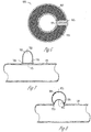
- FIGS. 7 and 8 illustrate lateral cross sectional views of examples of extra-vascular devices 700 and 800, respectively.
- device 700 includes compliant volume 725 defined by a flexible membrane 715 and the walls of device 700.
- the undeformed shape of the compliant volume can assume many shapes including, but not limited to, cylindrical, ellipsoidal, polygonal volumes with mitered, concave or convex features along the length of the compliant volume.
- membrane 715 has a flat, circular cross-sectional area and a length specified to encompass a volume sufficient to realize the desired therapeutic effect.
- membrane 715 is concave with respect to the compliant volume.
- Membrane 715 is located at aperture 710 and provides a fluid-tight joint between 725 and the lumen of artery 105.
- Device 700 is secured to the vasculature or surrounding tissue with feature 720 or by other anchor structure.
- feature 720 can include a suture however an adhesive or endothelial growth can also provide an anchor.
- feature 720 is disposed on an external surface of artery 105.
- membrane 715 is exposed to pulsatile pressure loads in artery 105. Under positive differential pressure, blood flowing in artery 105 presses against the device 700 and deforms membrane 715 such that an equivalent volume of blood occupies the space of the compliant volume. Under negative differential pressure, membrane 715 returns to the original, undeformed position.
- FIG. 8 illustrates an example in which device 800 includes a wall fabricated of a resilient material.
- Volume 825 has a variable volume based on deflection of device 800 and position of membrane 815.
- Membrane 815 is located at aperture 810.
- Feature 820 provides an anchoring structure for affixing device 800 to artery 105.
- Feature 820 is disposed on an interior surface of artery 105.
- Device 800 assumes a generally bulbous shape with increasing pressure within artery 105.
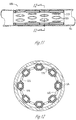
- FIGS. 9 and 10 illustrate device 900 having compliant body 920 and a central compliant volume.
- FIG. 9 illustrates a front view
- FIG. 10 illustrates a top view.
- Device 900 is configured for placement within the branches of a main pulmonary artery (left and right).
- the undeformed shape of the central compliant volume is defined by a flexible membrane of body 920 that can assume many shapes including, but not limited to, cylindrical, ellipsoidal, polygonal cross-sections with mitered, concave, or convex features along the length of the central compliant volume.
- the flexible membrane forms a triangular volume shape of a given length, base and height based on the central compliant volume required for specific patient therapeutic requirements.
- one or more surfaces defined by the flexible membrane can be of a different material with different stiffness and compliance properties.
- Device 900 is secured within the blood vessel lumen with an anchor structure.
- compliant body 920 is secured within blood vessel lumen by a scaffold-like structure for placement near a bifurcating vasculature anatomy.
- the scaffold-like structure includes structural rings 910 and 915 attached to the support structure base 930 at angles from 0 to 180 degrees as defined by an included angle measured from a surface of the compliant body 920 to the planar surface of structural ring 910 or 915.
- Structural rings 910 and 915 can be located in or near the bifurcating vasculature anatomy, respectively, to anchor the compliant body 920 at, or near, the bifurcation and are distributed around the periphery of the support structure base 930 at a location to locate structural rings 910 and 915 in the bifurcating vessels.
- a diameter of rings 910 and 915 are a function of the diameter of the bifurcating vessels.
- the support member 940 attaches to the support structure base 930 at appropriate locations along the periphery of the support structure base 930 at a first end and to the lower support base 950 at appropriate locations along the periphery of the lower support base 950 at the second end.
- the support member 940 and lower support base 950 are located in the primary vessel with support member 940 of a length to provide the support structure base 930 with sufficient lateral support to prevent embolization during systolic/diastolic heart function.
- the diameter of lower support base 950 is selectable based on the anatomy of the particular patient into which the device will be inserted.
- Support structures 910, 915, 930, 940, and 950 are made of bio-compatible, shape memory alloy materials such nitinol.
- device 900 is secured in position to allow the compliant body 920 to be suspended within the blood vessel lumen.
- the compliant body 920 is exposes to pulsatile pressure loads in the blood vessel lumen. Under positive differential pressure, blood flowing in the vessel lumen presses against the device 900 and deforms the flexible membrane such that an equivalent volume of blood occupies the space of the compliant volume. Under negative differential pressure, the flexible membrane returns to the original, undeformed position.
- Device 900 provides increased vessel compliance and is configured to divert acoustic waves to reduce reflections and the effects of afterloading.
- FIGS. 11 and 12 illustrate a sagittal and transverse cross sectional views, respectively, of fenestrated device 1100 in artery 105.
- Device 1100 includes compliant body 1110 in the form of a toroidal balloon.
- a plurality of fenestrations 1115 are provided in the balloon and the perimeter of each fenestration 1115 is bonded to retain a closed volume within compliant body 1110.
- the bonded perimeters of each fenestration 1115 presents an appearance similar to that of quilt stitching.
- the aperture of each fenestration 1115 provides a region where endothelium cells on the inner walls of artery 105 infuse and bond with the compliant body 1110, thus holding device 1100 at a fixed location within artery 105.
- Fenestrations 1115 are depicted as oval shapes and in various examples, can include longitudinal slits or rectangular windows.
- the portions of compliant body 1110 located between adjacent fenestrations may take on a faceted appearance in which the portions of compliant body 1110 that are bonded to the inner wall of artery 105 are joined by relatively straight segments of inflated balloon material.
- FIG. 12 the cell growth between the compliant body 1110 and the wall of artery 105 is not shown.
- the web of material between the fenestrations can be biased to enlarge the bore of the lumen by selection of suitable materials for the inner and outer portions of the toroidal balloon, by selection of material thickness.
- an internal structure can be molded within the balloon to provide a specified bore.
- an installation tool having a stent-like support structure can be used to temporarily bring the web into contact with the vessel wall and thereby promote endothelial cell growth.
- the number of fenestrations and the arrangement of fenestrations and balloon material can be tailored to provide a larger or smaller number of contact points with the arterial wall.
- adjacent balloon segments defined between fenestrations
- the compliant volume of device 1100 is defined by the toroidal balloon and lies between the fenestrations.
- the undeformed shape of device 1100 is defined by a flexible membrane of compliant body 1110 into which a quilted pattern of holes 1115 is fenestrated to allow endothelial tissue growth over the surface of the flexible membrane.
- the undeformed shape of the compliant volume can assume many shapes including, but not limited to, cylindrical, ellipsoidal, polygonal cross-sections with mitered, concave or convex features along the length of the compliant volume.
- the flexible membrane is formed into a toroidal cylindrical shape of a length and diameter based on the compliant volume required for specific patient therapeutic requirements.
- device 1100 is separated into individual compliant bodies 1110 of a length less than the total length required to achieve specific patient therapeutic requirements and deployed into the artery 105 to convenient locations as required to realize the compliant volume required for patient therapeutic requirements.
- Device 1100 is secured to the vasculature by an anchor structure or feature.
- the diameter of the flexible membrane is selected to ensure intimate contact of the flexible membrane with the artery 105 wall resulting in sufficient friction between the flexible membrane and the artery 105 wall to prevent embolization of device 1100.
- device 1100 is located within the vasculature and the compliant body 1110 is exposed to pulsatile pressure loads.
- blood flowing in the blood vessel lumen of artery 105 presses against the compliant body 1110 and deforms the flexible membrane such that an equivalent volume of blood occupies the space of the compliant volume.
- negative differential pressure the flexible membrane returns to the original, undeformed position.
- FIGS. 12 and 14 illustrate lateral and transverse cross sectional views of device 1300 according to one example.
- device 1300 includes compliant body 1310 with a central compliant body 1310 with a central compliant volume 1315, the undeformed shape of which is defined by a flexible membrane designed for implantation between and within the muscular layers of a blood vessel, such as artery 105.
- the undeformed shape of the central compliant volume 1315 defined by a flexible membrane can assume many shapes including, but not limited to, cylindrical, ellipsoidal, polygonal cross-sections with mitered, concave, or convex features along the length of the central compliant volume 1315.
- the flexible membrane is formed into an oblong cylindrical cross-sectional shape of a given length and central diameter based on the central compliant volume 1315 required for patient therapeutic requirements.
- Device 1300 is secured to the vasculature with an anchor structure.
- device 1300 is positioned between muscular layers of artery 105 ensuring intimate contact of the device 1300 with the artery 105, thus resulting in sufficient friction between the flexible membrane and the lumen wall of artery 105 to prevent embolization of the device 1300.
- device 1300 In operation, device 1300 is located within the vasculature and is exposed to pulsatile pressure loads. Under positive differential pressure, blood flowing in the vessel lumen of artery 105 presses against the blood vessel lumen wall which in turn deforms the flexible membrane of compliant body 1310 such that an equivalent volume of blood occupies the space of the compliant volume 1315. Under negative differential pressure, the flexible membrane returns to the original, undeformed position as defined insertion within the artery 105.
- FIG. 13 depicts device 1300 located within void 95 of an interior portion of the vessel wall.
- Void 95 can include a region between two layers of a wall or within a single particular layer.
- FIGS. 15 and 16 illustrate lateral cross sectional views of device 1500 according to one example.
- device 1500 includes frame 1525 and diaphragm 1510 which cooperatively define a volume.
- Diaphragm 1510 is two stable modes and in one example, includes a flexible membrane.
- the flexible membrane can include a polymer or a metal (formed or stamped) to have bimodal configurations.
- diaphragm 1510 is illustrated to bow away from frame 1525 and extend into the lumen of artery 105, thereby defining volume 1520A.
- diaphragm 1510 is illustrated to bow toward frame 1525 and away from the center of the lumen of artery 105, thereby defining volume 1520B.
- Volume 1520B is less than volume 1520A and the air or gas therebetween can be vented to a larger region.
- diaphragm 1510 remains stable without undue influence.
- Diaphragm 1510 can maintain one of two stable positions, namely, a state of negative differential pressure ( FIG. 15 ) and a state of positive differential pressure ( FIG. 16 ).
- Device 1500 includes a compliant body with a central compliant volume (1520A and 1520B) the undeformed shape of which is defined by a diaphragm 1510 which is configured to remain in either a concave mode or a convex mode with respect to the central compliant volume.
- the undeformed shape of the central compliant volume defined by a diaphragm 1510 can assume many shapes including, but not limited to, cylindrical, ellipsoidal, polygonal cross-sections with mitered, concave, or convex features along the length of the central compliant volume.
- the diaphragm 1510 is formed into a rectangular cross-sectional shape of a given length based on the central compliant volume required for patient therapeutic requirements.
- Device 1500 is secured to the vasculature using frame 1525.
- frame 1525 can be sutured to a blood vessel lumen wall (artery 105) to prevent embolization of the device 1500.
- Device 1500 is located within the blood vessel lumen and is held in a fixed position by other structure to suspend device 1500 within the lumen.
- device 1500 is located within the blood vessel lumen and is exposed to pulsatile pressure loads. Under positive differential pressure, blood flowing in the blood vessel lumen presses against the diaphragm 1510 until such time that sufficient force is generated over the area of the diaphragm 1510 that the buckling strength of the flexible membrane is exceeded and the diaphragm 1510 becomes convex with respect to the central compliant volume.
- the pressure contained within the central compliant volume presses against the diaphragm 1510 until such time that sufficient force is generated over the area of diaphragm 1510 that the buckling strength of diaphragm 1510 is exceeded and diaphragm 1510 becomes concave with respect to the central compliant volume whereby the diaphragm 1510 is returned to the original, undeformed position.
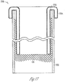
- FIG. 17 illustrates a portion of device 1700 according to one example.
- Device 1700 includes coaxial outer tube 1050 and inner tube 1704 having a rolled, or everted end as shown at the top of the figure.
- Voice 1702 between outer tube 1050 and inner tube 1704 provides a variable volume region.
- Inner tube 1704 is fabricated of an elastic or compliant material.
- Void 1702 can be precharged with a predetermined pressure. Variations in fluid pressure in a fluid (such as blood) flowing through the lumen of inner tube 1704 will cause a change in the volume at void 1702.
- a port in outer tube 1050 can be used to provide a precharge.
- Device 1700 can be held in a fixed position within and artery or organ using interface 110 or other anchor structure.
- the energy storage device includes a membrane in one example.
- the membrane provides a barrier to separate the blood (or other fluid) from the variable volume region.
- the membrane in one example, is unstressed until the onset of pressure from the fluid. With the onset of pressure, the membrane is deflected from the initial position and takes on a distended mode. Modulation of pressure within the organ causes a corresponding modulation of the membrane position. The pressure in the variable volume region will also modulate with change in position of the membrane.
- variable volume region is pressurized with a pre-charge including a gas or a fluid.
- the pre-charge can be delivered by a syringe, conversion of a liquid or solid substance to a gaseous phase (i.e., to off-gas a vapor), or by physical manipulation of the membrane.
- a variable volume region can have a pre-charge gas pressure selected based on various factors, including, for example, the blood pressure or the stiffness of the membrane. In one example, the pre-charge is approximately 85% of the typical pressure in that organ.
- variable volume region can be pressurized after implantation.
- a syringe or other means can be used to recharge the energy storage device. Recharging can include directly injecting a gas or fluid into the device. The injection can be delivered through a port on an exterior portion of the body (or through an arterial wall).
- variable volume region can be pressurized using a compressible gas such as carbon dioxide, air, nitrogen, argon, helium, or other gas.
- a compressible gas such as carbon dioxide, air, nitrogen, argon, helium, or other gas.
- a large molecule gas is selected to reduce incidence of gas leak-down through the membrane.
- nitric oxide is selected for pressurizing the region. Nitric oxide gas leaked from a membrane and into an artery can provide a therapeutic benefit to the tissue.
- An example of the present subject matter can be implanted in the pulmonary artery.
- Other locations include placement in the right of left main pulmonary artery (MPA).
- MPA main pulmonary artery
- a device is located within a lumen of the artery and retained by a suspension or support structure.
- the device presents a volume that varies with pressure changes.
- the device is coupled to an artery by a fluid-tight joint.
- the fluid tight joint can be the result of endothelial cell development, by an adhesive, or other structure.
- the energy storage device is passively operated based on pressure dynamics within the organ. As the pressure rises, energy is absorbed and upon reduction in pressure, the energy is returned to the fluidic system. In one example, the energy storage device is actively modulated. Active modulation can include a motor-driven piston or membrane, a piezo-electric element, or other device that can be modulated by an external energy source.
- a plurality of compressible gaseous bubbles can be delivered to the organ using a suitable manifold.
- the volume of the bubbles will modulate with changes in the pressure within the fluidic system.
- the delivery manifold can include an annular ring configured to emit bubbles into the organ.
- such a device includes a sealed gas chamber above a bodily fluid (such as blood).
- the gas chamber (or variable volume region) can be separated by a fluid-gas interface (without a barrier or membrane) or can include a resilient membrane (diaphragm).
- the membrane can be in the form of a planar diaphragm or in the form of a bladder or balloon.
- the membrane can take a continuously variable position within its range of freedom or can have any number of indexed modes. For example, a bi-stable membrane can have a first mode or a second mode corresponding to different volumes.
- the energy storage device includes a gas-charged piston or a spring-loaded piston.
- a gas-charged piston example includes a free-floating piston with a seal between the piston wall and the cylinder wall.
- the energy storage device can be located internal to an organ (e.g., wholly within the channel), external to the organ (e.g., coupled to an artery by a fluidic channel), or located partially internal and partially external (e.g., in a wall of a vessel).
- the surface area of the membrane, working deflection range of the membrane, and the pre-charge of the variable volume region can be selected to suit a particular application.
- multiple devices can be used in series or in parallel configuration.
Claims (8)
- Dispositif comprenant :un ballonnet (115, 1510) présentant une surface externe et une forme cylindrique, le ballonnet (115, 1510) étant configuré pour recevoir un fluide compressible de telle sorte que le ballonnet (115, 1510) se déforme sous une pression différentielle positive, le ballonnet (115, 1510) étant configuré en outre pour reprendre une position non déformée initiale sous une pression différentielle négative ; etune interface (110, 1525) configurée pour être couplée à la surface externe, l'interface (110, 1525) présentant une surface externe configurée pour se lier à un tissu de l'artère pulmonaire.
- Dispositif selon la revendication 1, dans lequel le ballonnet (115, 1510) comporte une pluralité de fenestrations (1115).
- Dispositif selon la revendication 1 ou 2, dans lequel l'interface (110, 1525) comporte au moins un échafaudage, un stent ou un manchon cylindrique.
- Dispositif selon l'une quelconque des revendications 1 à 3, dans lequel la surface externe est configurée pour permettre un développement de cellules endothéliales.
- Dispositif selon l'une quelconque des revendications 1 à 4, dans lequel l'interface (110, 1525) est configurée pour fournir un joint étanche aux liquides avec le tissu de l'artère pulmonaire.
- Dispositif selon l'une quelconque des revendications 1 à 5, dans lequel l'interface (110, 1525) comprend un filet non métallique.
- Dispositif selon l'une quelconque des revendications 1 à 6, dans lequel l'interface (110, 1525) comprend un filet métallique.
- Dispositif selon l'une quelconque des revendications 1 à 7, dans lequel l'interface (110, 1525) est configurée pour s'élargir lors de son déploiement pour entrer intimement en contact avec la paroi de l'artère pulmonaire.
Applications Claiming Priority (2)
| Application Number | Priority Date | Filing Date | Title |
|---|---|---|---|
| US35277410P | 2010-06-08 | 2010-06-08 | |
| PCT/US2011/038558 WO2011156176A1 (fr) | 2010-06-08 | 2011-05-31 | Elastance vasculaire |
Publications (3)
| Publication Number | Publication Date |
|---|---|
| EP2579809A1 EP2579809A1 (fr) | 2013-04-17 |
| EP2579809A4 EP2579809A4 (fr) | 2017-03-29 |
| EP2579809B1 true EP2579809B1 (fr) | 2020-11-25 |
Family
ID=45098375
Family Applications (1)
| Application Number | Title | Priority Date | Filing Date |
|---|---|---|---|
| EP11792905.9A Active EP2579809B1 (fr) | 2010-06-08 | 2011-05-31 | Elastance vasculaire |
Country Status (3)
| Country | Link |
|---|---|
| US (3) | US9987153B2 (fr) |
| EP (1) | EP2579809B1 (fr) |
| WO (1) | WO2011156176A1 (fr) |
Families Citing this family (16)
| Publication number | Priority date | Publication date | Assignee | Title |
|---|---|---|---|---|
| US20080300528A1 (en) * | 2007-05-29 | 2008-12-04 | Creativasc Medical Llc | Arteriovenous access valve system and process |
| US20090030498A1 (en) | 2007-05-29 | 2009-01-29 | Creativasc Medical | Arteriovenous Access Valve System and Process |
| WO2011156176A1 (fr) | 2010-06-08 | 2011-12-15 | Regents Of The University Of Minnesota | Elastance vasculaire |
| JP5782523B2 (ja) | 2010-11-22 | 2015-09-24 | アリア シーブイ, インコーポレイテッド | 脈動圧力を減少させるためのシステムおよび方法 |
| US8876850B1 (en) | 2014-06-19 | 2014-11-04 | Aria Cv, Inc. | Systems and methods for treating pulmonary hypertension |
| EP3169251A4 (fr) * | 2014-07-20 | 2018-03-14 | Elchanan Bruckheimer | Appareil de pose d'implant dans l'artère pulmonaire et ses procédés d'utilisation |
| US10420538B2 (en) | 2015-02-05 | 2019-09-24 | Obp Medical Corporation | Illuminated surgical retractor |
| US20170042551A1 (en) | 2015-08-13 | 2017-02-16 | The Brain Protection Company PTY LTD | Implantable damping devices for treating dementia and associated systems and methods of use |
| US10376681B2 (en) | 2016-02-29 | 2019-08-13 | Edwards Lifesciences Corporation | Vacuum-based compliance restoration |
| US11771434B2 (en) | 2016-09-28 | 2023-10-03 | Restore Medical Ltd. | Artery medical apparatus and methods of use thereof |
| US11331105B2 (en) | 2016-10-19 | 2022-05-17 | Aria Cv, Inc. | Diffusion resistant implantable devices for reducing pulsatile pressure |
| WO2018200972A1 (fr) * | 2017-04-28 | 2018-11-01 | Regents Of The University Of Minnesota | Greffes de stent aortique compliantes et systèmes et procédés associés |
| CN110691554B (zh) | 2017-06-05 | 2022-11-01 | 恢复医疗有限公司 | 双壁固定长度的支架状设备及其使用方法 |
| CA3131354A1 (fr) * | 2018-02-20 | 2019-08-29 | QHeart Medical Pty Ltd | Dispositif de traitement de vaisseau pliable et reglable et manchon perfectionne avec modes de charge et de decharge independants et commandes dynamiquement pour un traitement d'u n vaisseau ou d'une paroi de sac et dispositif d'assistance cardiaque |
| US11318029B2 (en) | 2018-06-13 | 2022-05-03 | Michael Warren Sutherland | Pulmonary arterial compliance enhancement device |
| WO2021046252A1 (fr) | 2019-09-06 | 2021-03-11 | Aria Cv, Inc. | Dispositifs implantables résistants à la diffusion et à la perfusion pour réduire la pression pulsatile |
Family Cites Families (135)
| Publication number | Priority date | Publication date | Assignee | Title |
|---|---|---|---|---|
| US3275001A (en) | 1962-05-22 | 1966-09-27 | Kendall & Co | Self-inflatable catheter |
| US3634924A (en) | 1970-04-20 | 1972-01-18 | American Hospital Supply Corp | Method of making multilumen balloon catheter |
| US3818903A (en) | 1973-04-11 | 1974-06-25 | Bard Inc C R | Self-inflating catheter with deflating means and reservoir |
| US4422447A (en) | 1981-04-13 | 1983-12-27 | Peter Schiff | Percutaneous balloon |
| US4902273A (en) | 1984-02-21 | 1990-02-20 | Choy Daniel S J | Heart assist device |
| DE3621350A1 (de) | 1986-06-26 | 1988-01-14 | Bonzel Tassilo | Dilatationskatheter mit einem aufweitbaren ballon |
| US4793351A (en) | 1987-06-15 | 1988-12-27 | Mansfield Scientific, Inc. | Multi-lumen balloon catheter |
| US4938766A (en) | 1987-08-28 | 1990-07-03 | Jarvik Robert K | Prosthetic compliance devices |
| US5084015A (en) | 1988-05-16 | 1992-01-28 | Terumo Kabushiki Kaisha | Catheter assembly of the hypodermic embedment type |
| GB8825236D0 (en) * | 1988-10-28 | 1988-11-30 | Franklin W | Improvements in & relating to endotracheal tube |
| WO1990006086A1 (fr) | 1988-11-25 | 1990-06-14 | Leadon Pty Ltd | Dispositif a soupape |
| US4955905A (en) | 1989-06-26 | 1990-09-11 | Reed Andrew M | Method and apparatus for monitoring pressure of human tissue expansion devices |
| CA2067110C (fr) | 1989-09-08 | 2001-07-31 | John E. Abele | Angioplastie a faible stress physiologique |
| US5112303A (en) | 1991-05-02 | 1992-05-12 | Pudenz-Schulte Medical Research Corporation | Tumor access device and method for delivering medication into a body cavity |
| US5795325A (en) | 1991-07-16 | 1998-08-18 | Heartport, Inc. | Methods and apparatus for anchoring an occluding member |
| US5766151A (en) | 1991-07-16 | 1998-06-16 | Heartport, Inc. | Endovascular system for arresting the heart |
| US5222980A (en) | 1991-09-27 | 1993-06-29 | Medtronic, Inc. | Implantable heart-assist device |
| US5578085A (en) | 1991-11-27 | 1996-11-26 | Board Of Regents The University Of Texas System | Balloon prosthesis for the lung and methods of making and using same |
| US5509900A (en) | 1992-03-02 | 1996-04-23 | Kirkman; Thomas R. | Apparatus and method for retaining a catheter in a blood vessel in a fixed position |
| US5769821A (en) | 1992-03-02 | 1998-06-23 | Quinton Instrument Company | Catheter tip retainer |
| US5409444A (en) | 1992-03-04 | 1995-04-25 | Kensey Nash Corporation | Method and apparatus to reduce injury to the vascular system |
| US6623516B2 (en) | 1992-08-13 | 2003-09-23 | Mark A. Saab | Method for changing the temperature of a selected body region |
| US5499995C1 (en) | 1994-05-25 | 2002-03-12 | Paul S Teirstein | Body passageway closure apparatus and method of use |
| US5486192A (en) | 1994-06-03 | 1996-01-23 | Walinsky; Paul | Cyclic coronary angioplasty system |
| WO1996000095A1 (fr) | 1994-06-23 | 1996-01-04 | Minimed Inc. | Pompe de perfusion de medicaments a siege de soupape en fluoropolymere |
| US6048330A (en) | 1994-10-20 | 2000-04-11 | Children's Medical Center Corporation | Systems and methods for promoting tissue growth |
| US5858003A (en) | 1994-10-20 | 1999-01-12 | Children's Medical Center Corporation | Systems and methods for promoting tissue growth |
| DE19508129C2 (de) | 1995-03-08 | 1997-02-13 | Jan Dr Med Menke | Blutdurchflußeinstelleinrichtung zur wahlweisen externen Verengung und Erweiterung des Blutdurchflußquerschnittes eines Blutgefäßes |
| US5688237A (en) | 1995-05-04 | 1997-11-18 | Cedars-Sinai Medical Center | Implantable catheter and method of use |
| FR2744924B1 (fr) | 1996-02-21 | 1998-04-24 | Franchi Pierre | Dispositif generateur/regulateur de pression pour pompe d'assistance cardiaque implantable du type a ballonnet de contrepression |
| US5713867A (en) | 1996-04-29 | 1998-02-03 | Medtronic, Inc. | Introducer system having kink resistant splittable sheath |
| US5797879A (en) | 1996-08-26 | 1998-08-25 | Decampli; William M. | Apparatus and methods for providing selectively adjustable blood flow through a vascular graft |
| US5820542A (en) | 1996-10-31 | 1998-10-13 | Momentum Medical, Inc. | Modified circulatory assist device |
| US5833655A (en) | 1997-05-15 | 1998-11-10 | L. Vad Technology, Inc. | Percutaneous access device having removable turret assembly |
| US6579224B1 (en) | 1999-10-11 | 2003-06-17 | Uromedica, Inc. | Apparatus and method for inserting an adjustable implantable genitourinary device |
| DE69739334D1 (de) | 1997-07-16 | 2009-05-07 | Metacure N V | Einrichtung zur Steuerung eines glatten Muskels |
| FR2766373B1 (fr) | 1997-07-24 | 1999-08-27 | Commissariat Energie Atomique | Dispositif d'assistance cardiaque ventriculaire a contre-pulsation |
| US6168586B1 (en) | 1998-08-07 | 2001-01-02 | Embol-X, Inc. | Inflatable cannula and method of using same |
| US6261304B1 (en) | 1998-09-10 | 2001-07-17 | Percardia, Inc. | Delivery methods for left ventricular conduit |
| US6368345B1 (en) | 1998-09-30 | 2002-04-09 | Edwards Lifesciences Corporation | Methods and apparatus for intraluminal placement of a bifurcated intraluminal garafat |
| US6017324A (en) | 1998-10-20 | 2000-01-25 | Tu; Lily Chen | Dilatation catheter having a bifurcated balloon |
| US6210318B1 (en) | 1999-03-09 | 2001-04-03 | Abiomed, Inc. | Stented balloon pump system and method for using same |
| AU4684500A (en) | 1999-04-30 | 2000-11-17 | Uromedica, Inc. | Method and apparatus for adjustable sling for treatment of urinary stress incontinence |
| SE514718C2 (sv) | 1999-06-29 | 2001-04-09 | Jan Otto Solem | Anordning för behandling av bristande tillslutningsförmåga hos mitralisklaffapparaten |
| US6461367B1 (en) | 1999-07-16 | 2002-10-08 | Loma Linda University Medical Center | Method and device for urethral-vesicle anastomosis |
| US6136025A (en) | 1999-07-27 | 2000-10-24 | Barbut; Denise R. | Endoscopic arterial pumps for treatment of cardiac insufficiency and venous pumps for right-sided cardiac support |
| US6184431B1 (en) | 1999-08-23 | 2001-02-06 | Shell Oil Company | Process for separating internal and alpha olefins from saturated compounds |
| US8579966B2 (en) | 1999-11-17 | 2013-11-12 | Medtronic Corevalve Llc | Prosthetic valve for transluminal delivery |
| FR2815844B1 (fr) | 2000-10-31 | 2003-01-17 | Jacques Seguin | Support tubulaire de mise en place, par voie percutanee, d'une valve cardiaque de remplacement |
| US10327880B2 (en) | 2000-04-14 | 2019-06-25 | Attenuex Technologies, Inc. | Attenuation device for use in an anatomical structure |
| US6682473B1 (en) | 2000-04-14 | 2004-01-27 | Solace Therapeutics, Inc. | Devices and methods for attenuation of pressure waves in the body |
| IL137090A (en) * | 2000-06-29 | 2010-04-15 | Pentech Medical Devices Ltd | Polymeric stent |
| US7077825B1 (en) | 2002-01-16 | 2006-07-18 | Radiant Medical, Inc. | Method for gastric cooling using balloon catheter |
| US20040093007A1 (en) | 2002-05-31 | 2004-05-13 | Anthony Sussman | Intraluminal occlusion device and method |
| WO2004014257A1 (fr) | 2002-08-08 | 2004-02-19 | Neovasc Medical Ltd. | Regulateur de debit de forme geometrique |
| US9307991B2 (en) | 2002-08-22 | 2016-04-12 | Ams Research, Llc | Anastomosis device and related methods |
| JP2005538807A (ja) | 2002-09-17 | 2005-12-22 | トライカーディア, エル.エル.シー. | 血管の伸展性デバイスおよび使用の方法 |
| US20040111006A1 (en) * | 2002-12-17 | 2004-06-10 | Scout Medical Technologies, Llc | System and method for regulating blood pressure |
| US7468050B1 (en) | 2002-12-27 | 2008-12-23 | L. Vad Technology, Inc. | Long term ambulatory intra-aortic balloon pump |
| US7150758B2 (en) | 2003-03-06 | 2006-12-19 | Boston Scientific Santa Rosa Corp. | Kink resistant endovascular graft |
| US8116883B2 (en) | 2003-06-04 | 2012-02-14 | Synecor Llc | Intravascular device for neuromodulation |
| US7008438B2 (en) | 2003-07-14 | 2006-03-07 | Scimed Life Systems, Inc. | Anchored PTCA balloon |
| US7736362B2 (en) | 2003-09-15 | 2010-06-15 | Boston Scientific Scimed, Inc. | Catheter balloons |
| US7056286B2 (en) | 2003-11-12 | 2006-06-06 | Adrian Ravenscroft | Medical device anchor and delivery system |
| US7766814B2 (en) * | 2004-03-02 | 2010-08-03 | Peter William Walsh | Vessel or sac wall treatment and a cardiac assist device |
| EP1744804A4 (fr) * | 2004-05-03 | 2009-11-04 | Fulfillium Inc | Procede et systeme de commande du volume gastrique |
| US7497854B2 (en) | 2004-05-07 | 2009-03-03 | Ethicon Endo-Surgery, Inc. | Method and instrument for effecting anastomosis of respective tissues defining two body lumens |
| US8012079B2 (en) | 2004-08-13 | 2011-09-06 | Procyrion, Inc. | Method and apparatus for long-term assisting a left ventricle to pump blood |
| US7261725B2 (en) | 2005-01-13 | 2007-08-28 | Binmoeller Kenneth F | Endoscopic device with independently actuated legs |
| US20060135962A1 (en) | 2004-09-09 | 2006-06-22 | Kick George F | Expandable trans-septal sheath |
| US20060085028A1 (en) | 2004-10-18 | 2006-04-20 | Robert Boock | Vessel occlusion system |
| US20060093642A1 (en) | 2004-11-03 | 2006-05-04 | Ranade Shrirang V | Method of incorporating carbon nanotubes in a medical appliance, a carbon nanotube medical appliance, and a medical appliance coated using carbon nanotube technology |
| US8226592B2 (en) | 2004-12-15 | 2012-07-24 | Rox Medical, Inc. | Method of treating COPD with artificial arterio-venous fistula and flow mediating systems |
| GB0428257D0 (en) | 2004-12-23 | 2005-01-26 | Harefield Cardiac Ltd | A blood circulation assistance device |
| JP3855171B2 (ja) | 2005-01-07 | 2006-12-06 | 独立行政法人理化学研究所 | Maldi質量分析用試料の調製方法及びそのための試薬組成物 |
| US8096937B2 (en) | 2005-01-11 | 2012-01-17 | Otologics, Llc | Adaptive cancellation system for implantable hearing instruments |
| SE531468C2 (sv) | 2005-04-21 | 2009-04-14 | Edwards Lifesciences Ag | En anordning för styrning av blodflöde |
| CA2616037A1 (fr) | 2005-07-21 | 2007-02-01 | The Cleveland Clinic Foundation | Dispositifs medicaux oscillants intracraniens et leurs utilisations |
| EP1940316B1 (fr) * | 2005-09-26 | 2015-10-21 | AttenueX Technologies, Inc. | Dispositif d'attenuation de pression |
| DE102005051849B4 (de) | 2005-10-28 | 2010-01-21 | JenaValve Technology Inc., Wilmington | Vorrichtung zur Implantation und Befestigung von Herzklappenprothesen |
| BRPI0505102A (pt) | 2005-11-22 | 2007-08-07 | Renato Samy Assad | aperfeiçoamentos introduzidos em dispositivo de bandagem do tronco pulmonar |
| US20070293848A1 (en) | 2005-12-06 | 2007-12-20 | Morinobu Endo | Medical Instrument |
| DE102005060197A1 (de) | 2005-12-14 | 2007-06-21 | Rheinisch-Westfälisch Technische Hochschule Aachen | Kathetervorrichtung |
| US20070142819A1 (en) | 2005-12-20 | 2007-06-21 | El-Nounou Fozan O | Bifurcated catheter for agent delivery and method of agent delivery |
| US8043206B2 (en) | 2006-01-04 | 2011-10-25 | Allergan, Inc. | Self-regulating gastric band with pressure data processing |
| CA2673650A1 (fr) | 2006-10-05 | 2008-04-17 | Anil B. Kumar | Catheter a ballonnet pourvu d'une valve actionnee manuellement et d'un aspirateur |
| GB0623395D0 (en) | 2006-11-23 | 2007-01-03 | Renishaw Plc | Port |
| US20080147181A1 (en) | 2006-12-19 | 2008-06-19 | Sorin Biomedica Cardio S.R.L. | Device for in situ axial and radial positioning of cardiac valve prostheses |
| US8442639B2 (en) | 2007-02-13 | 2013-05-14 | Cardiac Pacemakers, Inc. | Systems and methods for electrical stimulation of blood vessels |
| US7942863B2 (en) | 2007-03-29 | 2011-05-17 | Medtronic, Inc. | Detecting needle entry into a port of an infusion device |
| US9017362B2 (en) * | 2007-06-13 | 2015-04-28 | Cook Medical Technologies Llc | Occluding device |
| EP2155051A1 (fr) | 2007-06-14 | 2010-02-24 | Cardiac Pacemakers, Inc. | Procédés et dispositifs de mesure de pression intracorporelle |
| EP2016961B1 (fr) | 2007-07-18 | 2010-02-17 | Surgery in Motion Ltd. | Dispositif d'assistance cardiaque |
| US8002744B2 (en) | 2007-08-06 | 2011-08-23 | Bard Peripheral Vascular, Inc | Non-compliant medical balloon |
| US8613721B2 (en) | 2007-11-14 | 2013-12-24 | Medrad, Inc. | Delivery and administration of compositions using interventional catheters |
| US7835797B2 (en) | 2007-12-04 | 2010-11-16 | Cvrx, Inc. | Method and system for implantable pressure transducer for regulating blood pressure |
| WO2009100242A2 (fr) | 2008-02-06 | 2009-08-13 | Guided Delivery Systems, Inc. | Tunnel de guidage à fenêtres multiples |
| EP2252362A1 (fr) | 2008-02-07 | 2010-11-24 | University of Pittsburgh - Of the Commonwealth System of Higher Education | Dispositifs, systèmes et procédés d échange de gaz intracorporel |
| US8128617B2 (en) | 2008-05-27 | 2012-03-06 | Boston Scientific Scimed, Inc. | Electrical mapping and cryo ablating with a balloon catheter |
| CN102186436B (zh) | 2008-08-13 | 2016-02-10 | 拜纳瑞克斯医学有限公司 | 用于管状体部的衬垫以及用于施加衬垫的设备和方法 |
| CA2734493C (fr) | 2008-08-19 | 2016-09-27 | Tissuegen, Inc. | Dispositif medical auto-dilatable |
| US8366602B2 (en) | 2008-10-22 | 2013-02-05 | Allergan, Inc. | Electrically activated valve for implantable fluid handling system |
| US20100185049A1 (en) | 2008-10-22 | 2010-07-22 | Allergan, Inc. | Dome and screw valves for remotely adjustable gastric banding systems |
| US8672917B2 (en) | 2009-01-05 | 2014-03-18 | Medtronic, Inc. | Pressure monitoring to control delivery of therapeutic agent |
| US20100204590A1 (en) | 2009-02-09 | 2010-08-12 | Edwards Lifesciences Corporation | Detection of Vascular Conditions Using Arterial Pressure Waveform Data |
| EP3146937B1 (fr) | 2009-04-28 | 2019-10-02 | Corvia Medical, Inc. | Dispositifs de traitement d'une insuffisance cardiaque |
| EP2509508A4 (fr) | 2009-12-08 | 2015-11-18 | Aum Cardiovascular Inc | Systèmes et procédés destinés à détecter une maladie cardiovasculaire |
| WO2011156176A1 (fr) | 2010-06-08 | 2011-12-15 | Regents Of The University Of Minnesota | Elastance vasculaire |
| US9737660B2 (en) | 2010-08-25 | 2017-08-22 | Medtronic, Inc. | Drug infusion device with controllable valve |
| US20130165964A1 (en) | 2010-09-21 | 2013-06-27 | Regents Of The University Of Minnesota | Active pressure control for vascular disease states |
| US9352172B2 (en) | 2010-09-30 | 2016-05-31 | Hologic, Inc. | Using a guide member to facilitate brachytherapy device swap |
| JP5782523B2 (ja) | 2010-11-22 | 2015-09-24 | アリア シーブイ, インコーポレイテッド | 脈動圧力を減少させるためのシステムおよび方法 |
| US8747386B2 (en) | 2010-12-16 | 2014-06-10 | Ams Research Corporation | Anastomosis device and related methods |
| US8562509B2 (en) | 2010-12-30 | 2013-10-22 | Cook Medical Technologies Llc | Ventricular assist device |
| US8206378B1 (en) | 2011-04-13 | 2012-06-26 | Medtronic, Inc. | Estimating the volume of fluid in therapeutic fluid delivery device reservoir |
| KR102109391B1 (ko) | 2011-11-28 | 2020-05-13 | 미-바드, 아이엔씨. | 심실 보조 장치 및 방법 |
| US20140370246A1 (en) | 2012-01-20 | 2014-12-18 | Brown University | Substrate with Graphene-based Layer |
| CA2868853C (fr) | 2012-03-26 | 2021-02-09 | Procyrion, Inc. | Systemes et procedes de circulation et de perfusion permettant d'ameliorer l'ecoulement et/ou la pression des liquides organiques |
| CN102657910A (zh) | 2012-05-31 | 2012-09-12 | 骆助林 | 一种t型双腔球囊扩张引流管 |
| US20130331921A1 (en) | 2012-06-08 | 2013-12-12 | Gary Roubin | Bifurcated catheter |
| US8894563B2 (en) | 2012-08-10 | 2014-11-25 | Attenuex Technologies, Inc. | Methods and systems for performing a medical procedure |
| JP6356152B2 (ja) | 2013-01-24 | 2018-07-11 | グラフトウォークス, インコーポレイテッド | 管腔を通る流動を測定するための装置 |
| GB201310578D0 (en) | 2013-06-13 | 2013-07-31 | Univ Nottingham Trent | Electroactive actuators |
| WO2015102693A2 (fr) | 2013-09-30 | 2015-07-09 | William Marsh Rice University | Composites à base de nanorubans de graphène perméables aux gaz et leurs procédés de fabrication |
| US9421017B2 (en) | 2014-01-15 | 2016-08-23 | Jacques Seguin | Methods and apparatus using branched balloon for treating pulmonary arterial hypertension |
| FR3016279A1 (fr) | 2014-01-15 | 2015-07-17 | Jacques Seguin | Dispositif de traitement de l'hypertension arterielle pulmonaire |
| US9427236B2 (en) | 2014-01-31 | 2016-08-30 | Jacques Seguin | Methods and apparatus using an anchored balloon for treating pulmonary arterial hypertension |
| FR3017044A1 (fr) | 2014-01-31 | 2015-08-07 | Jacques Seguin | Dispositif de traitement de l'hypertension arterielle pulmonaire |
| WO2015133849A1 (fr) | 2014-03-07 | 2015-09-11 | 한양대학교 산학협력단 | Membrane nanocomposite d'oxyde de graphène présentant des caractéristiques de barrière contre les gaz améliorées et son procédé de fabrication |
| US10166372B2 (en) | 2014-06-06 | 2019-01-01 | Cook Medical Technologies Llc | Angioplasty balloon improved with graphene |
| US8876850B1 (en) | 2014-06-19 | 2014-11-04 | Aria Cv, Inc. | Systems and methods for treating pulmonary hypertension |
| WO2016171763A1 (fr) | 2015-04-23 | 2016-10-27 | Obalon Therapeutics, Inc. | Systèmes et méthodes de détermination de défaillance de dispositifs intragastriques |
| US10376681B2 (en) | 2016-02-29 | 2019-08-13 | Edwards Lifesciences Corporation | Vacuum-based compliance restoration |
| US11331105B2 (en) | 2016-10-19 | 2022-05-17 | Aria Cv, Inc. | Diffusion resistant implantable devices for reducing pulsatile pressure |
| WO2021046252A1 (fr) | 2019-09-06 | 2021-03-11 | Aria Cv, Inc. | Dispositifs implantables résistants à la diffusion et à la perfusion pour réduire la pression pulsatile |
-
2011
- 2011-05-31 WO PCT/US2011/038558 patent/WO2011156176A1/fr active Application Filing
- 2011-05-31 US US13/701,721 patent/US9987153B2/en active Active
- 2011-05-31 EP EP11792905.9A patent/EP2579809B1/fr active Active
-
2018
- 2018-05-30 US US15/993,572 patent/US10617538B2/en active Active
-
2020
- 2020-04-07 US US16/842,612 patent/US11583420B2/en active Active
Non-Patent Citations (1)
| Title |
|---|
| None * |
Also Published As
| Publication number | Publication date |
|---|---|
| US11583420B2 (en) | 2023-02-21 |
| US20180271681A1 (en) | 2018-09-27 |
| US20130079871A1 (en) | 2013-03-28 |
| US10617538B2 (en) | 2020-04-14 |
| EP2579809A1 (fr) | 2013-04-17 |
| WO2011156176A1 (fr) | 2011-12-15 |
| US20200229950A1 (en) | 2020-07-23 |
| EP2579809A4 (fr) | 2017-03-29 |
| US9987153B2 (en) | 2018-06-05 |
Similar Documents
| Publication | Publication Date | Title |
|---|---|---|
| US11583420B2 (en) | Vascular elastance | |
| US10702682B2 (en) | System and method for reducing pulsatile pressure | |
| EP3160528B1 (fr) | Dispositif de support cardiaque | |
| US9433715B2 (en) | Stable aortic blood pump implant | |
| US6572533B1 (en) | Cardiac disease treatment and device | |
| US7854762B2 (en) | Devices and methods for reducing cardiac valve regurgitation | |
| CN104334119A (zh) | 单环心脏瓣膜支撑结构 | |
| US8821571B2 (en) | Compensatory container | |
| US7374531B1 (en) | Long term ambulatory intra-aortic balloon pump with three dimensional tortuous shape | |
| US20090131741A1 (en) | Methods of making aortic counter pulsation cardiac assist devices with three dimensional tortuous shape |
Legal Events
| Date | Code | Title | Description |
|---|---|---|---|
| PUAI | Public reference made under article 153(3) epc to a published international application that has entered the european phase |
Free format text: ORIGINAL CODE: 0009012 |
|
| 17P | Request for examination filed |
Effective date: 20130108 |
|
| AK | Designated contracting states |
Kind code of ref document: A1 Designated state(s): AL AT BE BG CH CY CZ DE DK EE ES FI FR GB GR HR HU IE IS IT LI LT LU LV MC MK MT NL NO PL PT RO RS SE SI SK SM TR |
|
| DAX | Request for extension of the european patent (deleted) | ||
| RA4 | Supplementary search report drawn up and despatched (corrected) |
Effective date: 20170301 |
|
| RIC1 | Information provided on ipc code assigned before grant |
Ipc: A61F 2/06 20130101AFI20170223BHEP |
|
| STAA | Information on the status of an ep patent application or granted ep patent |
Free format text: STATUS: EXAMINATION IS IN PROGRESS |
|
| 17Q | First examination report despatched |
Effective date: 20190830 |
|
| GRAP | Despatch of communication of intention to grant a patent |
Free format text: ORIGINAL CODE: EPIDOSNIGR1 |
|
| STAA | Information on the status of an ep patent application or granted ep patent |
Free format text: STATUS: GRANT OF PATENT IS INTENDED |
|
| INTG | Intention to grant announced |
Effective date: 20200709 |
|
| RIN1 | Information on inventor provided before grant (corrected) |
Inventor name: SCANDURRA, JOHN Inventor name: SCORZELLI, CHRISTOPHER Inventor name: VOLLMERS, KARL Inventor name: LITTLE, ERIC F. |
|
| GRAS | Grant fee paid |
Free format text: ORIGINAL CODE: EPIDOSNIGR3 |
|
| GRAA | (expected) grant |
Free format text: ORIGINAL CODE: 0009210 |
|
| STAA | Information on the status of an ep patent application or granted ep patent |
Free format text: STATUS: THE PATENT HAS BEEN GRANTED |
|
| AK | Designated contracting states |
Kind code of ref document: B1 Designated state(s): AL AT BE BG CH CY CZ DE DK EE ES FI FR GB GR HR HU IE IS IT LI LT LU LV MC MK MT NL NO PL PT RO RS SE SI SK SM TR |
|
| REG | Reference to a national code |
Ref country code: GB Ref legal event code: FG4D |
|
| REG | Reference to a national code |
Ref country code: CH Ref legal event code: EP |
|
| REG | Reference to a national code |
Ref country code: DE Ref legal event code: R096 Ref document number: 602011069432 Country of ref document: DE |
|
| REG | Reference to a national code |
Ref country code: AT Ref legal event code: REF Ref document number: 1337409 Country of ref document: AT Kind code of ref document: T Effective date: 20201215 |
|
| REG | Reference to a national code |
Ref country code: IE Ref legal event code: FG4D |
|
| REG | Reference to a national code |
Ref country code: AT Ref legal event code: MK05 Ref document number: 1337409 Country of ref document: AT Kind code of ref document: T Effective date: 20201125 |
|
| REG | Reference to a national code |
Ref country code: NL Ref legal event code: MP Effective date: 20201125 |
|
| PG25 | Lapsed in a contracting state [announced via postgrant information from national office to epo] |
Ref country code: FI Free format text: LAPSE BECAUSE OF FAILURE TO SUBMIT A TRANSLATION OF THE DESCRIPTION OR TO PAY THE FEE WITHIN THE PRESCRIBED TIME-LIMIT Effective date: 20201125 Ref country code: RS Free format text: LAPSE BECAUSE OF FAILURE TO SUBMIT A TRANSLATION OF THE DESCRIPTION OR TO PAY THE FEE WITHIN THE PRESCRIBED TIME-LIMIT Effective date: 20201125 Ref country code: NO Free format text: LAPSE BECAUSE OF FAILURE TO SUBMIT A TRANSLATION OF THE DESCRIPTION OR TO PAY THE FEE WITHIN THE PRESCRIBED TIME-LIMIT Effective date: 20210225 Ref country code: PT Free format text: LAPSE BECAUSE OF FAILURE TO SUBMIT A TRANSLATION OF THE DESCRIPTION OR TO PAY THE FEE WITHIN THE PRESCRIBED TIME-LIMIT Effective date: 20210325 Ref country code: GR Free format text: LAPSE BECAUSE OF FAILURE TO SUBMIT A TRANSLATION OF THE DESCRIPTION OR TO PAY THE FEE WITHIN THE PRESCRIBED TIME-LIMIT Effective date: 20210226 |
|
| PG25 | Lapsed in a contracting state [announced via postgrant information from national office to epo] |
Ref country code: BG Free format text: LAPSE BECAUSE OF FAILURE TO SUBMIT A TRANSLATION OF THE DESCRIPTION OR TO PAY THE FEE WITHIN THE PRESCRIBED TIME-LIMIT Effective date: 20210225 Ref country code: AT Free format text: LAPSE BECAUSE OF FAILURE TO SUBMIT A TRANSLATION OF THE DESCRIPTION OR TO PAY THE FEE WITHIN THE PRESCRIBED TIME-LIMIT Effective date: 20201125 Ref country code: IS Free format text: LAPSE BECAUSE OF FAILURE TO SUBMIT A TRANSLATION OF THE DESCRIPTION OR TO PAY THE FEE WITHIN THE PRESCRIBED TIME-LIMIT Effective date: 20210325 Ref country code: LV Free format text: LAPSE BECAUSE OF FAILURE TO SUBMIT A TRANSLATION OF THE DESCRIPTION OR TO PAY THE FEE WITHIN THE PRESCRIBED TIME-LIMIT Effective date: 20201125 Ref country code: PL Free format text: LAPSE BECAUSE OF FAILURE TO SUBMIT A TRANSLATION OF THE DESCRIPTION OR TO PAY THE FEE WITHIN THE PRESCRIBED TIME-LIMIT Effective date: 20201125 Ref country code: SE Free format text: LAPSE BECAUSE OF FAILURE TO SUBMIT A TRANSLATION OF THE DESCRIPTION OR TO PAY THE FEE WITHIN THE PRESCRIBED TIME-LIMIT Effective date: 20201125 |
|
| REG | Reference to a national code |
Ref country code: LT Ref legal event code: MG9D |
|
| PG25 | Lapsed in a contracting state [announced via postgrant information from national office to epo] |
Ref country code: HR Free format text: LAPSE BECAUSE OF FAILURE TO SUBMIT A TRANSLATION OF THE DESCRIPTION OR TO PAY THE FEE WITHIN THE PRESCRIBED TIME-LIMIT Effective date: 20201125 |
|
| PG25 | Lapsed in a contracting state [announced via postgrant information from national office to epo] |
Ref country code: CZ Free format text: LAPSE BECAUSE OF FAILURE TO SUBMIT A TRANSLATION OF THE DESCRIPTION OR TO PAY THE FEE WITHIN THE PRESCRIBED TIME-LIMIT Effective date: 20201125 Ref country code: EE Free format text: LAPSE BECAUSE OF FAILURE TO SUBMIT A TRANSLATION OF THE DESCRIPTION OR TO PAY THE FEE WITHIN THE PRESCRIBED TIME-LIMIT Effective date: 20201125 Ref country code: SM Free format text: LAPSE BECAUSE OF FAILURE TO SUBMIT A TRANSLATION OF THE DESCRIPTION OR TO PAY THE FEE WITHIN THE PRESCRIBED TIME-LIMIT Effective date: 20201125 Ref country code: LT Free format text: LAPSE BECAUSE OF FAILURE TO SUBMIT A TRANSLATION OF THE DESCRIPTION OR TO PAY THE FEE WITHIN THE PRESCRIBED TIME-LIMIT Effective date: 20201125 Ref country code: SK Free format text: LAPSE BECAUSE OF FAILURE TO SUBMIT A TRANSLATION OF THE DESCRIPTION OR TO PAY THE FEE WITHIN THE PRESCRIBED TIME-LIMIT Effective date: 20201125 Ref country code: RO Free format text: LAPSE BECAUSE OF FAILURE TO SUBMIT A TRANSLATION OF THE DESCRIPTION OR TO PAY THE FEE WITHIN THE PRESCRIBED TIME-LIMIT Effective date: 20201125 |
|
| REG | Reference to a national code |
Ref country code: DE Ref legal event code: R097 Ref document number: 602011069432 Country of ref document: DE |
|
| PG25 | Lapsed in a contracting state [announced via postgrant information from national office to epo] |
Ref country code: DK Free format text: LAPSE BECAUSE OF FAILURE TO SUBMIT A TRANSLATION OF THE DESCRIPTION OR TO PAY THE FEE WITHIN THE PRESCRIBED TIME-LIMIT Effective date: 20201125 |
|
| PLBE | No opposition filed within time limit |
Free format text: ORIGINAL CODE: 0009261 |
|
| STAA | Information on the status of an ep patent application or granted ep patent |
Free format text: STATUS: NO OPPOSITION FILED WITHIN TIME LIMIT |
|
| PG25 | Lapsed in a contracting state [announced via postgrant information from national office to epo] |
Ref country code: AL Free format text: LAPSE BECAUSE OF FAILURE TO SUBMIT A TRANSLATION OF THE DESCRIPTION OR TO PAY THE FEE WITHIN THE PRESCRIBED TIME-LIMIT Effective date: 20201125 Ref country code: NL Free format text: LAPSE BECAUSE OF FAILURE TO SUBMIT A TRANSLATION OF THE DESCRIPTION OR TO PAY THE FEE WITHIN THE PRESCRIBED TIME-LIMIT Effective date: 20201125 |
|
| 26N | No opposition filed |
Effective date: 20210826 |
|
| PG25 | Lapsed in a contracting state [announced via postgrant information from national office to epo] |
Ref country code: SI Free format text: LAPSE BECAUSE OF FAILURE TO SUBMIT A TRANSLATION OF THE DESCRIPTION OR TO PAY THE FEE WITHIN THE PRESCRIBED TIME-LIMIT Effective date: 20201125 Ref country code: ES Free format text: LAPSE BECAUSE OF FAILURE TO SUBMIT A TRANSLATION OF THE DESCRIPTION OR TO PAY THE FEE WITHIN THE PRESCRIBED TIME-LIMIT Effective date: 20201125 |
|
| REG | Reference to a national code |
Ref country code: CH Ref legal event code: PL |
|
| PG25 | Lapsed in a contracting state [announced via postgrant information from national office to epo] |
Ref country code: CH Free format text: LAPSE BECAUSE OF NON-PAYMENT OF DUE FEES Effective date: 20210531 Ref country code: MC Free format text: LAPSE BECAUSE OF FAILURE TO SUBMIT A TRANSLATION OF THE DESCRIPTION OR TO PAY THE FEE WITHIN THE PRESCRIBED TIME-LIMIT Effective date: 20201125 Ref country code: LU Free format text: LAPSE BECAUSE OF NON-PAYMENT OF DUE FEES Effective date: 20210531 Ref country code: LI Free format text: LAPSE BECAUSE OF NON-PAYMENT OF DUE FEES Effective date: 20210531 |
|
| REG | Reference to a national code |
Ref country code: BE Ref legal event code: MM Effective date: 20210531 |
|
| PG25 | Lapsed in a contracting state [announced via postgrant information from national office to epo] |
Ref country code: IS Free format text: LAPSE BECAUSE OF FAILURE TO SUBMIT A TRANSLATION OF THE DESCRIPTION OR TO PAY THE FEE WITHIN THE PRESCRIBED TIME-LIMIT Effective date: 20210325 |
|
| PG25 | Lapsed in a contracting state [announced via postgrant information from national office to epo] |
Ref country code: BE Free format text: LAPSE BECAUSE OF NON-PAYMENT OF DUE FEES Effective date: 20210531 |
|
| REG | Reference to a national code |
Ref country code: FR Ref legal event code: PLFP Year of fee payment: 13 |
|
| PG25 | Lapsed in a contracting state [announced via postgrant information from national office to epo] |
Ref country code: HU Free format text: LAPSE BECAUSE OF FAILURE TO SUBMIT A TRANSLATION OF THE DESCRIPTION OR TO PAY THE FEE WITHIN THE PRESCRIBED TIME-LIMIT; INVALID AB INITIO Effective date: 20110531 Ref country code: CY Free format text: LAPSE BECAUSE OF FAILURE TO SUBMIT A TRANSLATION OF THE DESCRIPTION OR TO PAY THE FEE WITHIN THE PRESCRIBED TIME-LIMIT Effective date: 20201125 |
|
| P01 | Opt-out of the competence of the unified patent court (upc) registered |
Effective date: 20230509 |
|
| PGFP | Annual fee paid to national office [announced via postgrant information from national office to epo] |
Ref country code: IT Payment date: 20230412 Year of fee payment: 13 Ref country code: IE Payment date: 20230412 Year of fee payment: 13 Ref country code: FR Payment date: 20230411 Year of fee payment: 13 Ref country code: DE Payment date: 20230404 Year of fee payment: 13 |
|
| PGFP | Annual fee paid to national office [announced via postgrant information from national office to epo] |
Ref country code: GB Payment date: 20230406 Year of fee payment: 13 |