EP2579420A2 - Drahtloses Ladegerät mit Positionsführungsmechanismus - Google Patents
Drahtloses Ladegerät mit Positionsführungsmechanismus Download PDFInfo
- Publication number
- EP2579420A2 EP2579420A2 EP11194912.9A EP11194912A EP2579420A2 EP 2579420 A2 EP2579420 A2 EP 2579420A2 EP 11194912 A EP11194912 A EP 11194912A EP 2579420 A2 EP2579420 A2 EP 2579420A2
- Authority
- EP
- European Patent Office
- Prior art keywords
- carrier
- electronic device
- wireless charger
- track
- wireless
- Prior art date
- Legal status (The legal status is an assumption and is not a legal conclusion. Google has not performed a legal analysis and makes no representation as to the accuracy of the status listed.)
- Withdrawn
Links
Images


Classifications
-
- H—ELECTRICITY
- H02—GENERATION; CONVERSION OR DISTRIBUTION OF ELECTRIC POWER
- H02J—CIRCUIT ARRANGEMENTS OR SYSTEMS FOR SUPPLYING OR DISTRIBUTING ELECTRIC POWER; SYSTEMS FOR STORING ELECTRIC ENERGY
- H02J7/00—Circuit arrangements for charging or depolarising batteries or for supplying loads from batteries
- H02J7/0042—Circuit arrangements for charging or depolarising batteries or for supplying loads from batteries characterised by the mechanical construction
- H02J7/0044—Circuit arrangements for charging or depolarising batteries or for supplying loads from batteries characterised by the mechanical construction specially adapted for holding portable devices containing batteries
-
- H—ELECTRICITY
- H02—GENERATION; CONVERSION OR DISTRIBUTION OF ELECTRIC POWER
- H02J—CIRCUIT ARRANGEMENTS OR SYSTEMS FOR SUPPLYING OR DISTRIBUTING ELECTRIC POWER; SYSTEMS FOR STORING ELECTRIC ENERGY
- H02J50/00—Circuit arrangements or systems for wireless supply or distribution of electric power
- H02J50/10—Circuit arrangements or systems for wireless supply or distribution of electric power using inductive coupling
-
- H—ELECTRICITY
- H02—GENERATION; CONVERSION OR DISTRIBUTION OF ELECTRIC POWER
- H02J—CIRCUIT ARRANGEMENTS OR SYSTEMS FOR SUPPLYING OR DISTRIBUTING ELECTRIC POWER; SYSTEMS FOR STORING ELECTRIC ENERGY
- H02J50/00—Circuit arrangements or systems for wireless supply or distribution of electric power
- H02J50/90—Circuit arrangements or systems for wireless supply or distribution of electric power involving detection or optimisation of position, e.g. alignment
Definitions
- the present invention relates to a wireless charger, and more particularly to a wireless charger with a position-guiding mechanism.
- the commercially available charger is equipped with a power cable. Through the power cable, the charger is in communication with the portable electronic device in physical connection for charging the portable electronic device.
- the portable electronic device and the charger are developed toward light weightiness and miniaturization.
- the charging plug of the power cable of the charger and the charging slot of the portable electronic device are both shrunken.
- the user wants to charge the portable electronic device, the user should carefully align the charging plug with the charging slot in order to inert the charging plug into the charging slot. In other words, the procedure of aligning the charging plug with the charging slot is very inconvenient.
- FIG. 1 is a schematic perspective view illustrating a wireless charger for charging a portable electronic device according to the prior art.
- the wireless charger 7 has a transmitter coil 71.
- a receiver coil 81 is included in the portable electronic device 8 for receiving signals from the transmitter coil 71 of the wireless charger 7, so that a wireless charging operation is performed.
- the charging efficiency for the wireless charging technology is principally dependent on whether the center of the receiver coil 81 and the center of the transmitter coil 71 are aligned with each other. Since the commercially available wireless charger 7 has no mechanism for precisely positioning the portable electronic device 8, the receiver coil 81 fails to be precisely aligned with the center of the transmitter coil 71. Under this circumstance, the efficiency of charging the portable electronic device 8 by the wireless charger 7 is deteriorated or the portable electronic device 8 fails to be accurately charged.
- the portable electronic device during operations of the conventional horizontal-type wireless charger, the portable electronic device should be deliberately located near or aligned with the center of the wireless charger.
- a position-guiding mechanism for precisely aligning the transmitter coil with the receiver coil, thereby increasing the charging efficiency and using flexibility.
- the present invention relates to a wireless charger with a position-guiding mechanism.
- the electronic device is precisely aligned with the wireless charger, so that the efficiency of charging the portable electronic device is enhanced.
- a wireless charger with a position-guiding mechanism An electronic device with a receiver coil is charged by the wireless charger.
- the wireless charger includes a wireless charging body, a carrier and an elastic element.
- the wireless charging body has a track and a transmitter coil.
- the carrier is used for supporting the electronic device, wherein the carrier includes an extension part, which is movably disposed on the track.
- the elastic element is connected with the carrier for providing a pulling force to the carrier, so that the carrier is maintained at an initial position.
- the carrier When the electronic device is held by the carrier, the carrier to be moved from the initial position to a charging position along the track in response to a gravity force of the electronic device, so that the receiver coil of the electronic device is aligned with the transmitter coil of the wireless charging body.
- the carrier When the electronic device is not held by the carrier, the carrier is returned to the initial position in response to the pulling force of the elastic element.
- the carrier further includes a main gear, wherein the main gear is pivotally coupled to the extension part through a shaft.
- the track has a plurality of first toothed structures, and the main gear is engaged with the first toothed structures.
- the main gear is rotated relative to the shaft.
- the carrier further includes a lateral arm and a bottom plate for supporting the electronic device.
- the lateral arm and the bottom plate are fixed on the main gear.
- the carrier is moved along the track in response to the gravity force of the electronic device, and the lateral arm and the bottom plate are rotated relative to the shaft through the main gear.
- the wireless charging body has a contact surface for supporting the electronic device, and the contact surface is located adjacent to the lateral arm and the bottom plate.
- the carrier is moved along the track in response to the gravity force of the electronic device, and the lateral arm and the bottom plate are rotated relative to the shaft through the main gear.
- the wireless charging body further includes a cushioning element, and the cushioning element is sustained against the extension part.
- the extension part has a plurality of second toothed structures, and the cushioning element is sustained against the second toothed structures.
- the cushioning element is a damping gear.
- the extension part of the carrier has a terminal part, wherein the elastic element is fixed on the terminal part of the carrier.
- the extension part of the carrier has a lateral surface, wherein the elastic element is fixed on the lateral surface of the extension part.
- the wireless charging body further includes a position-limiting element.
- the carrier is stopped by the position-limiting element, so that the position-limiting element is maintained at the initial position.
- the elastic element is a line spring.
- FIG. 1 is a schematic perspective view illustrating a wireless charger for charging a portable electronic device according to the prior art
- FIG. 2 is a schematic perspective view illustrating a wireless charger with a position-guiding mechanism according to an embodiment of the present invention
- FIG. 3 a schematic exploded view illustrating the wireless charger as shown in FIG. 2 ;
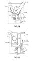
- FIG. 4A is a schematic front view illustrating a wireless charger with a position-guiding mechanism according to an embodiment of the present invention, in which the electronic device is not held by the carrier;
- FIG. 4B is a schematic front view illustrating a wireless charger with a position-guiding mechanism according to an embodiment of the present invention, in which the electronic device is held by the carrier.
- FIG. 2 is a schematic perspective view illustrating a wireless charger with a position-guiding mechanism according to an embodiment of the present invention.
- FIG. 3 a schematic exploded view illustrating the wireless charger as shown in FIG. 2 .
- the wireless charger 1 is used for charging an electronic device 4 that has a receiver coil 46.
- the wireless charger 1 comprises a wireless charging body 11, a carrier 13 and an elastic element 15.
- the wireless charging body 11 has a transmitter coil 110 and a track 112.
- the transmitter coil 110 is usually disposed within the wireless charging body 11.
- the receiver coil 46 takes power from the electromagnetic field and converts the power into an electric current.
- the electric current is transmitted to the electronic device 4 to charge the electronic device 4.
- the elastic element 15 is connected with the carrier 13 and the wireless charging body 11.
- the elastic element 15 is disposed within the wireless charging body 11 for maintaining a concise appearance of the wireless charger 1.
- the way of connecting the elastic element 15 and the carrier 13 is not restricted as long as the carrier 13 is able to be maintained at an initial position relative to the wireless charging body 11.
- the elastic restoring force provided by the elastic element 15 is a pulling force. Before the electronic device 4 is held by the carrier 13, the carrier 13 is pulled by the elastic element 15 to be maintained and positioned at the initial position.
- the carrier 13 has an extension part 132.
- the extension part 132 is movably disposed on the track 112.
- the track 112 of the wireless charging body 11 is substantially arranged in a vertical direction (but is not limited to the vertical direction). That is, the track 112 is arranged along the line directed to the earth's center. Due to a gravity force, the carrier 13 may be moved along the track 112.
- the carrier 13 is used for holding the electronic device 4. When the electronic device 4 is held by the carrier 13, the carrier 13 is moved from the initial position to a charging position along the track 112 in response to the gravity force of the electronic device.
- the charging position is a position where the electronic device 4 is charged the most efficiently by the wireless charging body 11.
- the charging operation is performed by the wireless charger 1 when the electronic device 4 is at the charging position.
- the elastic element 15 which is connected with the carrier 13 and the wireless charging body 11 is subject to tensile deformation. Due to the tensile deformation, an elastic potential energy is stored in the elastic element 15.
- the carrier 13 is returned to the initial position.
- FIG. 4A is a schematic front view illustrating a wireless charger with a position-guiding mechanism according to an embodiment of the present invention, in which the electronic device is not held by the carrier.
- FIG. 4B is a schematic front view illustrating a wireless charger with a position-guiding mechanism according to an embodiment of the present invention, in which the electronic device is held by the carrier.
- the carrier 13 comprises a main gear 135.
- the main gear 135 is pivotally coupled to the extension part 132 through a shaft 136. Consequently, the main gear 135 is rotatable relative to the extension part 132.
- the carrier 13 further comprises a lateral arm 138 and a bottom plate 139 for holding the electronic device 4.
- the main gear 135 is fixed on the lateral arm 138 and the bottom plate 139. Consequently, as the main gear 135 is rotated, the lateral arm 138 and the bottom plate 139 are synchronously rotated with the main gear 135 by the same angle, and rotated relative to the extension part 132. Moreover, in this embodiment, the main gear 135 and the extension part 132 are disposed within the wireless charging body 11, and the lateral arm 138 and the bottom plate 139 are disposed outside the wireless charging body 11. The shaft 136 is penetrated through a slot 115 of the wireless charging body 11, so that the lateral arm 138 and the bottom plate 139 are fixed on the main gear 135.
- the track 112 of the wireless charging body 11 has a plurality of first toothed structures 112a.
- the first toothed structures 112a are engaged with the peripheral toothed surface 135a of the main gear 135.
- the first toothed structures 112a are successively arranged along the track 112a (e.g. in the vertical direction).
- the wireless charging body 11 further comprises a cushioning element 119.
- the cushioning element 119 is sustained against the extension part 132 for slightly hindering the downward movement of the extension part 132 while reducing the moving speed of the carrier 13 downwardly.
- the extension part 132 has a plurality of second toothed structures 132a.
- the second toothed structures 132a are formed on both edges of the extension part 132, and the cushioning element 119 could be a damping gear.
- the cushioning element 119 comprises a pair of damping gears, which are respectively sustained against the second toothed structures 132a on the both edges of the extension part 132. Consequently, the gravity force loaded on the damping gears can be uniformly exerted on the damping gears.
- the carrier 13 When the carrier 13 to be moved downwardly in response to the gravity force of the electronic device 4, the moving speed of the extension part 132 is reduced by means of the damping gears. Under this circumstance, the carrier 13 and the electronic device 4 can be smoothly moved downwardly at a steady speed.
- the wireless charging body 11 has a contact surface 113 to be contacted with the electronic device 4. Moreover, the contact surface 113 is located adjacent to the lateral arm 138 and the bottom plate 139. Consequently, the electronic device 4 may be simultaneously leant against the contact surface 113 of the wireless charging body 11 and the lateral arm 138 and the bottom plate 139 of the carrier 13. At the same time, the carrier 13 to be moved along the track 112 in response to the gravity force of the electronic device, and the rotation of the main gear 135 may result in rotation of the lateral arm 138 and the bottom plate 139 relative to the shaft 136. Until the electronic device 4 supported on the carrier 13 is rotated to the charging position upon rotation of the lateral arm 138 and the bottom plate 139, the electronic device 4 is placed upright.
- the elastic element 15 is a line spring.
- the extension part 132 of the carrier 13 has a terminal part 132b, and an end of the elastic element 15 is fixed on the terminal part 132b of the carrier 13.
- the extension part 132 of the carrier 13 has a lateral surface 132c, and the elastic element 15 is fixed on the lateral surface 132c of the extension part 132. In such way, when the elastic potential energy stored in the elastic element 15 is released, the extension part 132 can be pulled back to the initial position.
- the wireless charging body 11 further comprises a position-limiting element 116 for limiting the position of the carrier 13.
- the position-limiting element 116 is sustained against the carrier 13 so as to prevent the carrier 13 from being overly displaced by the pulling force of the elastic element 15. Consequently, if the electronic device 4 is not held by the carrier 13, the carrier 13 is stopped by the position-limiting element 116 to be maintained at the initial position.
- the position-limiting element 116 may be sustained against the extension part 132 for stopping the carrier 13.
- the present invention provides wireless charger with a position-guiding mechanism.
- the carrier When the electronic device is placed on the carrier by the user, the carrier may be self-moved to the charging position in response to the gravity force of the electronic device.
- the charging position is a position where the electronic device is charged the most efficiently by the wireless charger.
- the receiver coil of the electronic device and the transmitter coil of the wireless charger can be precisely aligned with each other, the efficiency of charging the electronic device will be enhanced. Consequently, the drawbacks encountered from the prior art will be obviated.
Applications Claiming Priority (1)
| Application Number | Priority Date | Filing Date | Title |
|---|---|---|---|
| TW100136605A TWI433424B (zh) | 2011-10-07 | 2011-10-07 | 具有導引定位機構之無線充電器 |
Publications (1)
| Publication Number | Publication Date |
|---|---|
| EP2579420A2 true EP2579420A2 (de) | 2013-04-10 |
Family
ID=45470318
Family Applications (1)
| Application Number | Title | Priority Date | Filing Date |
|---|---|---|---|
| EP11194912.9A Withdrawn EP2579420A2 (de) | 2011-10-07 | 2011-12-21 | Drahtloses Ladegerät mit Positionsführungsmechanismus |
Country Status (4)
| Country | Link |
|---|---|
| US (1) | US20130088193A1 (de) |
| EP (1) | EP2579420A2 (de) |
| JP (1) | JP2013085433A (de) |
| TW (1) | TWI433424B (de) |
Cited By (4)
| Publication number | Priority date | Publication date | Assignee | Title |
|---|---|---|---|---|
| DE102014113886A1 (de) | 2013-10-04 | 2015-04-09 | Faurecia Interieur Industrie | Drahtloses Ladegerät für ein elektronisches Gerät und Fahrzeuginnenausrüstung, die ein derartiges Ladegerät umfasst |
| US9577449B2 (en) | 2014-01-17 | 2017-02-21 | Honda Motor Co., Ltd. | Method and apparatus to align wireless charging coils |
| CN107147167A (zh) * | 2017-05-24 | 2017-09-08 | 深圳市安思科电子科技有限公司 | 一种安放可靠的无线充电设备 |
| CN108964199A (zh) * | 2018-08-07 | 2018-12-07 | Oppo广东移动通信有限公司 | 电子设备、无线充电管理系统以及无线充电管理方法 |
Families Citing this family (10)
| Publication number | Priority date | Publication date | Assignee | Title |
|---|---|---|---|---|
| TWI495982B (zh) * | 2012-08-10 | 2015-08-11 | Wistron Corp | 底座及具有其之電子組件 |
| TWI528673B (zh) | 2014-01-02 | 2016-04-01 | 鴻騰精密科技股份有限公司 | 無線充電基座 |
| US9300151B2 (en) * | 2014-02-25 | 2016-03-29 | Youhua Technology (Shenzhen) Co., Ltd. | Wireless charging device |
| US20150326053A1 (en) * | 2014-05-09 | 2015-11-12 | Lenovo (Singapore) Pte. Ltd. | Foldable wireless charging system |
| WO2016054535A1 (en) * | 2014-10-03 | 2016-04-07 | Robert Bosch Gmbh | Inductive charging holster for power tool |
| US9793727B2 (en) | 2014-10-10 | 2017-10-17 | Samsung-Electro-Mechanics Co., Ltd. | Apparatus for wireless charging |
| US9887576B2 (en) | 2014-12-24 | 2018-02-06 | Robert Bosch Tool Corporation | Inductive charging holster for power tools in mobile applications |
| CN208062821U (zh) * | 2018-02-06 | 2018-11-06 | 黄星辉 | 无线充电器 |
| CN112398203B (zh) * | 2020-11-30 | 2023-11-21 | 维沃移动通信有限公司 | 无线充电器及电子设备组件 |
| CN115333260A (zh) * | 2022-10-17 | 2022-11-11 | 北京紫光芯能科技有限公司 | 用于调整磁链的方法及装置、无线充电接收设备 |
Family Cites Families (16)
| Publication number | Priority date | Publication date | Assignee | Title |
|---|---|---|---|---|
| JPH1141381A (ja) * | 1997-07-16 | 1999-02-12 | Tamura Electric Works Ltd | 公衆電話機 |
| JP2000037047A (ja) * | 1998-07-15 | 2000-02-02 | Mitsumi Electric Co Ltd | 電磁誘導型充電装置 |
| US7126450B2 (en) * | 1999-06-21 | 2006-10-24 | Access Business Group International Llc | Inductively powered apparatus |
| JP2003125252A (ja) * | 2001-10-16 | 2003-04-25 | Olympus Optical Co Ltd | 電子カメラ、充電装置、及び電子カメラシステム |
| JP4618769B2 (ja) * | 2003-12-18 | 2011-01-26 | 国立大学法人 東京大学 | 回転伸縮リンク機構 |
| US7352567B2 (en) * | 2005-08-09 | 2008-04-01 | Apple Inc. | Methods and apparatuses for docking a portable electronic device that has a planar like configuration and that operates in multiple orientations |
| JP5166773B2 (ja) * | 2007-05-28 | 2013-03-21 | ソニーモバイルコミュニケーションズ株式会社 | 無接点電力伝送装置 |
| JP5072690B2 (ja) * | 2008-04-04 | 2012-11-14 | シャープ株式会社 | 無接点式充電装置 |
| TWI478460B (zh) * | 2009-01-06 | 2015-03-21 | Access Business Group Int Llc | 感應式電源供應器及其系統 |
| JP2010279240A (ja) * | 2009-04-27 | 2010-12-09 | Panasonic Corp | 非接触充電装置 |
| JP2010273466A (ja) * | 2009-05-22 | 2010-12-02 | Nidec Copal Electronics Corp | 非接触充電器の送電コイルの移動装置 |
| JP2011010378A (ja) * | 2009-06-23 | 2011-01-13 | Panasonic Corp | 非接触充電システム |
| JP5365748B2 (ja) * | 2009-12-28 | 2013-12-11 | 豊田合成株式会社 | 携帯型電子デバイス用の再充電または接続トレイ |
| TWM393909U (en) * | 2010-07-02 | 2010-12-01 | ming-xiang Ye | Double-sided wireless charger |
| JP5348183B2 (ja) * | 2010-08-18 | 2013-11-20 | 三洋電機株式会社 | 電池内蔵機器と充電装置 |
| US9124105B2 (en) * | 2010-12-07 | 2015-09-01 | Bryce Robert Gunderman | Wireless charging shelf |
-
2011
- 2011-10-07 TW TW100136605A patent/TWI433424B/zh not_active IP Right Cessation
- 2011-11-14 JP JP2011248714A patent/JP2013085433A/ja active Pending
- 2011-12-21 EP EP11194912.9A patent/EP2579420A2/de not_active Withdrawn
-
2012
- 2012-01-13 US US13/350,002 patent/US20130088193A1/en not_active Abandoned
Non-Patent Citations (1)
| Title |
|---|
| None |
Cited By (6)
| Publication number | Priority date | Publication date | Assignee | Title |
|---|---|---|---|---|
| DE102014113886A1 (de) | 2013-10-04 | 2015-04-09 | Faurecia Interieur Industrie | Drahtloses Ladegerät für ein elektronisches Gerät und Fahrzeuginnenausrüstung, die ein derartiges Ladegerät umfasst |
| US9912202B2 (en) | 2013-10-04 | 2018-03-06 | Faurecia Interieur Industrie | Wireless charger for an electronic device and vehicle interior equipment comprising such a charger |
| US9577449B2 (en) | 2014-01-17 | 2017-02-21 | Honda Motor Co., Ltd. | Method and apparatus to align wireless charging coils |
| CN107147167A (zh) * | 2017-05-24 | 2017-09-08 | 深圳市安思科电子科技有限公司 | 一种安放可靠的无线充电设备 |
| CN107147167B (zh) * | 2017-05-24 | 2019-12-10 | 深圳市奥利弗科技有限公司 | 一种安放可靠的无线充电设备 |
| CN108964199A (zh) * | 2018-08-07 | 2018-12-07 | Oppo广东移动通信有限公司 | 电子设备、无线充电管理系统以及无线充电管理方法 |
Also Published As
| Publication number | Publication date |
|---|---|
| JP2013085433A (ja) | 2013-05-09 |
| TW201316648A (zh) | 2013-04-16 |
| TWI433424B (zh) | 2014-04-01 |
| US20130088193A1 (en) | 2013-04-11 |
Similar Documents
| Publication | Publication Date | Title |
|---|---|---|
| EP2579420A2 (de) | Drahtloses Ladegerät mit Positionsführungsmechanismus | |
| EP1998423B1 (de) | Kontaktlose Stromübertragungsvorrichtung | |
| US8395353B2 (en) | Wireless charging transmitter for portable electronic device | |
| CN102854927B (zh) | 用于便携式电子装置的坞站 | |
| US8605425B2 (en) | Docking station for electronic device | |
| CN106331930A (zh) | 一种无线耳机的充电盒和适配该充电盒的无线耳机 | |
| US20120169275A1 (en) | Wireless charging receiver for portable electronic device | |
| US9935486B2 (en) | Wireless charging device | |
| EP2472697A1 (de) | Drahtloser Ladesender für tragbare elektronische Geräte | |
| CN208806622U (zh) | 一种无线充电装置 | |
| US11050276B2 (en) | Wireless charging device | |
| US9017086B2 (en) | Detachable electronic apparatus | |
| US8242743B2 (en) | Mouse with battery chamber and battery charging circuit | |
| EP2472696A1 (de) | Drahtloser Ladeempfänger für tragbare elektronische Geräte | |
| KR20120109892A (ko) | 차량용 무선전력전송기 | |
| CN210517260U (zh) | 一种充电头 | |
| EP3840341B1 (de) | Mobiles endgerät | |
| CN112152324B (zh) | 无线充电装置 | |
| US20210044124A1 (en) | Dock Base for Wirelessly Charging Intelligent Handheld Devices | |
| CN214154055U (zh) | 充电设备及充电系统 | |
| CN219145052U (zh) | 一种便携式无线储能充电装置 | |
| CN110392131A (zh) | 移动终端 | |
| KR102570376B1 (ko) | 태블릿 pc용 무선 충전장치 | |
| CN210608620U (zh) | 一种充电卡座及其充电系统 | |
| US20190386500A1 (en) | Portable wireless charging apparatus |
Legal Events
| Date | Code | Title | Description |
|---|---|---|---|
| PUAI | Public reference made under article 153(3) epc to a published international application that has entered the european phase |
Free format text: ORIGINAL CODE: 0009012 |
|
| AK | Designated contracting states |
Kind code of ref document: A2 Designated state(s): AL AT BE BG CH CY CZ DE DK EE ES FI FR GB GR HR HU IE IS IT LI LT LU LV MC MK MT NL NO PL PT RO RS SE SI SK SM TR |
|
| AX | Request for extension of the european patent |
Extension state: BA ME |
|
| STAA | Information on the status of an ep patent application or granted ep patent |
Free format text: STATUS: THE APPLICATION IS DEEMED TO BE WITHDRAWN |
|
| 18D | Application deemed to be withdrawn |
Effective date: 20150701 |