EP2579356A2 - Batteriemodul und verfahren zum anschluss einer zellenklemme einer batterie an ein vernetzungselement - Google Patents
Batteriemodul und verfahren zum anschluss einer zellenklemme einer batterie an ein vernetzungselement Download PDFInfo
- Publication number
- EP2579356A2 EP2579356A2 EP11792635.2A EP11792635A EP2579356A2 EP 2579356 A2 EP2579356 A2 EP 2579356A2 EP 11792635 A EP11792635 A EP 11792635A EP 2579356 A2 EP2579356 A2 EP 2579356A2
- Authority
- EP
- European Patent Office
- Prior art keywords
- reactive layer
- exothermal reactive
- cell terminal
- interconnect member
- exothermal
- Prior art date
- Legal status (The legal status is an assumption and is not a legal conclusion. Google has not performed a legal analysis and makes no representation as to the accuracy of the status listed.)
- Granted
Links
Images


Classifications
-
- H—ELECTRICITY
- H01—ELECTRIC ELEMENTS
- H01M—PROCESSES OR MEANS, e.g. BATTERIES, FOR THE DIRECT CONVERSION OF CHEMICAL ENERGY INTO ELECTRICAL ENERGY
- H01M50/00—Constructional details or processes of manufacture of the non-active parts of electrochemical cells other than fuel cells, e.g. hybrid cells
- H01M50/50—Current conducting connections for cells or batteries
- H01M50/543—Terminals
-
- B—PERFORMING OPERATIONS; TRANSPORTING
- B23—MACHINE TOOLS; METAL-WORKING NOT OTHERWISE PROVIDED FOR
- B23K—SOLDERING OR UNSOLDERING; WELDING; CLADDING OR PLATING BY SOLDERING OR WELDING; CUTTING BY APPLYING HEAT LOCALLY, e.g. FLAME CUTTING; WORKING BY LASER BEAM
- B23K26/00—Working by laser beam, e.g. welding, cutting or boring
- B23K26/20—Bonding
- B23K26/21—Bonding by welding
- B23K26/211—Bonding by welding with interposition of special material to facilitate connection of the parts
-
- B—PERFORMING OPERATIONS; TRANSPORTING
- B23—MACHINE TOOLS; METAL-WORKING NOT OTHERWISE PROVIDED FOR
- B23K—SOLDERING OR UNSOLDERING; WELDING; CLADDING OR PLATING BY SOLDERING OR WELDING; CUTTING BY APPLYING HEAT LOCALLY, e.g. FLAME CUTTING; WORKING BY LASER BEAM
- B23K1/00—Soldering, e.g. brazing, or unsoldering
- B23K1/0006—Exothermic brazing
-
- B—PERFORMING OPERATIONS; TRANSPORTING
- B23—MACHINE TOOLS; METAL-WORKING NOT OTHERWISE PROVIDED FOR
- B23K—SOLDERING OR UNSOLDERING; WELDING; CLADDING OR PLATING BY SOLDERING OR WELDING; CUTTING BY APPLYING HEAT LOCALLY, e.g. FLAME CUTTING; WORKING BY LASER BEAM
- B23K1/00—Soldering, e.g. brazing, or unsoldering
- B23K1/0008—Soldering, e.g. brazing, or unsoldering specially adapted for particular articles or work
- B23K1/0016—Soldering of electronic components
-
- B—PERFORMING OPERATIONS; TRANSPORTING
- B23—MACHINE TOOLS; METAL-WORKING NOT OTHERWISE PROVIDED FOR
- B23K—SOLDERING OR UNSOLDERING; WELDING; CLADDING OR PLATING BY SOLDERING OR WELDING; CUTTING BY APPLYING HEAT LOCALLY, e.g. FLAME CUTTING; WORKING BY LASER BEAM
- B23K1/00—Soldering, e.g. brazing, or unsoldering
- B23K1/005—Soldering by means of radiant energy
- B23K1/0056—Soldering by means of radiant energy soldering by means of beams, e.g. lasers, electron beams [EB]
-
- H—ELECTRICITY
- H01—ELECTRIC ELEMENTS
- H01M—PROCESSES OR MEANS, e.g. BATTERIES, FOR THE DIRECT CONVERSION OF CHEMICAL ENERGY INTO ELECTRICAL ENERGY
- H01M10/00—Secondary cells; Manufacture thereof
- H01M10/04—Construction or manufacture in general
- H01M10/0472—Vertically superposed cells with vertically disposed plates
-
- H—ELECTRICITY
- H01—ELECTRIC ELEMENTS
- H01M—PROCESSES OR MEANS, e.g. BATTERIES, FOR THE DIRECT CONVERSION OF CHEMICAL ENERGY INTO ELECTRICAL ENERGY
- H01M50/00—Constructional details or processes of manufacture of the non-active parts of electrochemical cells other than fuel cells, e.g. hybrid cells
- H01M50/50—Current conducting connections for cells or batteries
- H01M50/531—Electrode connections inside a battery casing
- H01M50/54—Connection of several leads or tabs of plate-like electrode stacks, e.g. electrode pole straps or bridges
-
- B—PERFORMING OPERATIONS; TRANSPORTING
- B23—MACHINE TOOLS; METAL-WORKING NOT OTHERWISE PROVIDED FOR
- B23K—SOLDERING OR UNSOLDERING; WELDING; CLADDING OR PLATING BY SOLDERING OR WELDING; CUTTING BY APPLYING HEAT LOCALLY, e.g. FLAME CUTTING; WORKING BY LASER BEAM
- B23K2101/00—Articles made by soldering, welding or cutting
- B23K2101/36—Electric or electronic devices
- B23K2101/38—Conductors
-
- Y—GENERAL TAGGING OF NEW TECHNOLOGICAL DEVELOPMENTS; GENERAL TAGGING OF CROSS-SECTIONAL TECHNOLOGIES SPANNING OVER SEVERAL SECTIONS OF THE IPC; TECHNICAL SUBJECTS COVERED BY FORMER USPC CROSS-REFERENCE ART COLLECTIONS [XRACs] AND DIGESTS
- Y02—TECHNOLOGIES OR APPLICATIONS FOR MITIGATION OR ADAPTATION AGAINST CLIMATE CHANGE
- Y02E—REDUCTION OF GREENHOUSE GAS [GHG] EMISSIONS, RELATED TO ENERGY GENERATION, TRANSMISSION OR DISTRIBUTION
- Y02E60/00—Enabling technologies; Technologies with a potential or indirect contribution to GHG emissions mitigation
- Y02E60/10—Energy storage using batteries
-
- Y—GENERAL TAGGING OF NEW TECHNOLOGICAL DEVELOPMENTS; GENERAL TAGGING OF CROSS-SECTIONAL TECHNOLOGIES SPANNING OVER SEVERAL SECTIONS OF THE IPC; TECHNICAL SUBJECTS COVERED BY FORMER USPC CROSS-REFERENCE ART COLLECTIONS [XRACs] AND DIGESTS
- Y02—TECHNOLOGIES OR APPLICATIONS FOR MITIGATION OR ADAPTATION AGAINST CLIMATE CHANGE
- Y02P—CLIMATE CHANGE MITIGATION TECHNOLOGIES IN THE PRODUCTION OR PROCESSING OF GOODS
- Y02P70/00—Climate change mitigation technologies in the production process for final industrial or consumer products
- Y02P70/50—Manufacturing or production processes characterised by the final manufactured product
-
- Y—GENERAL TAGGING OF NEW TECHNOLOGICAL DEVELOPMENTS; GENERAL TAGGING OF CROSS-SECTIONAL TECHNOLOGIES SPANNING OVER SEVERAL SECTIONS OF THE IPC; TECHNICAL SUBJECTS COVERED BY FORMER USPC CROSS-REFERENCE ART COLLECTIONS [XRACs] AND DIGESTS
- Y10—TECHNICAL SUBJECTS COVERED BY FORMER USPC
- Y10T—TECHNICAL SUBJECTS COVERED BY FORMER US CLASSIFICATION
- Y10T29/00—Metal working
- Y10T29/49—Method of mechanical manufacture
- Y10T29/49002—Electrical device making
- Y10T29/49108—Electric battery cell making
Definitions
- Battery modules have battery cells with cell terminals that are welded to interconnect devices.
- ultrasonic welding devices have a relatively long cycle time for welding cell terminals to interconnect devices.
- a welding tool of an ultrasonic welding device must be sequentially moved to each cell of a plurality of cell terminals that takes a relatively large amount of manufacturing time. Further, the welding tool must be allowed to cool between each weld that takes an additional amount of manufacturing time.
- the inventors herein have recognized a need for an improved battery module and methods for bonding a cell terminal of a battery module to an interconnect device.
- the battery module includes a battery cell having a cell terminal.
- the battery module further includes an exothermal reactive layer having first and second sides. The first side is disposed adjacent to the cell terminal.
- the battery module further includes an interconnect member disposed adjacent to the second side of the exothermal reactive layer.
- the exothermal reactive layer is configured to ignite to form a bonding joint between the interconnect member and the cell terminal in response to a laser beam contacting at least a portion of the exothermal reactive layer.
- a method for bonding a cell terminal of a battery to an interconnect member in accordance with another exemplary embodiment includes disposing an exothermal reactive layer between the interconnect member and the cell terminal of the battery cell, utilizing a component placement machine.
- the method further includes emitting a laser beam from a laser for a predetermined amount of time that contacts at least a portion of the exothermal reactive layer and ignites the exothermal reactive layer to form a bonding joint between the interconnect member and the cell terminal.
- a method for bonding a cell terminal of a battery to an interconnect member in accordance with another exemplary embodiment includes disposing the interconnect member having an exothermal reactive layer previously disposed thereon adjacent to the cell terminal utilizing a component placement machine. The method further includes emitting a laser beam from a laser for a predetermined amount of time that contacts at least a portion of the exothermal reactive layer and ignites the exothermal reactive layer to form a bonding joint between the interconnect member and the cell terminal.
- a method for bonding a cell terminal of a battery to an interconnect member in accordance with another exemplary embodiment includes disposing the cell terminal having an exothermal reactive layer previously disposed thereon adjacent to the interconnect layer utilizing a component placement machine. The method further includes emitting a laser beam from a laser for a predetermined amount of time that contacts at least a portion of the exothermal reactive layer and ignites the exothermal reactive layer to form a bonding joint between the interconnect member and the cell terminal.
- FIG. 1 is a schematic of a battery module in accordance with an exemplary embodiment
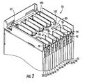
- FIG. 2 is a cross-sectional schematic of a top portion of the battery module of FIG. 1 ;
- FIG. 3 is a schematic of four battery cells and an interconnect member utilized in the battery module of FIG. 1 ;
- FIG. 4 is a cross-sectional schematic of the four battery cells and the interconnect member of FIG. 3 ;
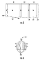
- FIG. 5 is a simplified enlarged cross-sectional schematic of a portion of an interconnect member, an exothermal reactive layer, and a cell terminal in accordance with another exemplary embodiment
- FIG. 6 is a simplified enlarged cross-sectional schematic of a portion of the exothermal reactive layer of FIG. 5 ;
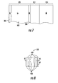
- FIG. 7 is a simplified enlarged cross-sectional schematic of a portion of an interconnect member, an exothermal reactive layer, and a cell terminal in accordance with another exemplary embodiment
- FIG. 8 is a simplified enlarged cross-sectional schematic of a portion of the exothermal reactive layer of FIG. 7 ;
- FIG. 9 is a block diagram of a system utilized to ignite an exothermal reactive layer disposed between a cell terminal and an interconnect member
- FIG. 10 is a flowchart of a method for bonding a cell terminal of the battery to an interconnect member in accordance with another exemplary embodiment
- FIG. 11 is a flowchart of another method for bonding a cell terminal of the battery to an interconnect member in accordance with another exemplary embodiment
- FIG. 12 is a flowchart of another method for bonding a cell terminal of the battery to an interconnect member in accordance with another exemplary embodiment
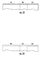
- FIG. 13 is a simplified enlarged cross-sectional schematic of a portion of an interconnect member, a bonding joint, and a cell terminal wherein the bonding joint is formed by igniting the exothermal reactive layer of FIG. 5 ;
- FIG. 14 is a simplified enlarged cross-sectional view of a portion of an interconnect member, a bonding joint, and a cell terminal wherein the bonding joint is formed by igniting the exothermal reactive layer of FIG. 7 .
- the battery module 10 includes battery cells 20, 22, 24, 26, 28, 30, 32, 34, 36, 38, 40, 42, 44, 46, 47, 48, 50, frame members 60, 62, 64, 66, 68, 70, 72, 74, 76, a circuit board 80, interconnect members 90, 92, 94, 96, 97, 98, 100, 102, 103 and exothermal reactive layers including exothermal reactive layers 110, 112.
- An advantage of the battery module 10 is that the module 10 utilizes exothermal reactive layers that can be ignited utilizing a laser beam during manufacture of the module 10 to bond cell terminals of the battery cells to associated interconnect members extremely quickly.
- An exothermal reactive layer refers to a layer which generates heat after being ignited.
- the battery cells 20-50 are lithium-ion battery cells. Further, the structure of the battery cells 20-50 are substantially similar to one another. Of course, in alternative embodiments, the battery cells could be other types of battery cells known to those skilled in the art.
- the battery cell 20 includes a body portion 130, an extension portion 132 extending around a periphery of the body portion 130, and cell terminals 134, 135 extending outwardly from the extension portion 132.
- the cell terminal 134 is a nickel-plated copper cell terminal and the cell terminal 135 is an aluminum cell terminal.
- the battery cell 22 includes a body portion 140, an extension portion 142 extending around a periphery of the body portion 140, and cell terminals 144, 145 extending outwardly from the extension portion 142.
- the cell terminal 144 is a nickel-plated copper cell terminal and the cell terminal 145 is an aluminum cell terminal.
- the battery cell 24 includes a body portion 150, an extension portion 152 extending around a periphery of the body portion 150, and cell terminals 154, 155 extending outwardly from the extension portion 152.
- the cell terminal 154 is a nickel-plated copper cell terminal and the cell terminal 155 is an aluminum cell terminal.
- the battery cell 26 includes a body portion 160, an extension portion 162 extending around a periphery of the body portion 160, and cell terminals 164, 165 extending outwardly from the extension portion 162.
- the cell terminal 164 is a nickel-plated copper cell terminal and the cell terminal 165 is an aluminum cell terminal.
- the frame members 60, 62, 64, 66, 68, 70, 72, 74, 76 are configured to be coupled together to enclose the battery cells 20-50 therebetween, and the frame members 60, 62 are configured to be coupled together and to hold the battery cells 20, 22 therebetween. Further, the frame members 62, 64 are configured to be coupled together and to hold the battery cells 24, 26 therebetween, and the frame members 64, 66 are configured to be coupled together and to hold battery cells 28, 30 therebetween. Also, the frame members 66, 68 are configured to be coupled together and to hold battery cells 32, 34 therebetween, and the frame members 68, 70 are configured to be coupled together and to hold battery cells 36, 38 therebetween.
- frame members 70, 72 are configured to be coupled together and to hold battery cells 40, 42 therebetween, and the frame members 72, 74 are configured to be coupled together and to hold battery cells 44, 46 therebetween. Finally, the frame members 74, 76 are configured to be coupled together and to hold battery cells 48, 50 therebetween.
- the interconnect members 90, 92, 94, 96, 97, 98, 100, 102, 103 are provided to electrically couple cell terminals of the battery cells 20-50 in series with one another. Since the interconnect members 90, 92, 94, 96, 98, 100, 102 have a substantially similar configuration, only the structure of interconnect member 90 will be discussed in detail.
- the interconnect member 90 is substantially U-shaped and has outer nickel layers 180, 184 and a central copper layer 182. As illustrated, a surface of the nickel layer 184 is disposed adjacent to a first side of the exothermal reactive layer 112 also having a nickel layer.
- the surface of the nickel layer 184 is disposed adjacent to a first side of the exothermal reactive layer 112 having an aluminum layer.
- a wall of the interconnect member 90 has a thickness in a range of 0.5-1.0 millimeters.
- the interconnect members 97 and 103 have a different shape than the other interconnect members, and the interconnect members 97 and 103 are constructed of the same materials as the other interconnect members.
- the exothermal reactive layer 112 is provided to ignite in response to a laser beam contacting the exothermal reactive layer 112 in order to form a bonding joint 700 between the interconnect member 90 and the cell terminal 154.
- the exothermal reactive layer 112 is constructed of a plurality of nickel layers 200 and a plurality of aluminum layers 202. Each nickel layer 200 has an adjacent aluminum layer 202 disposed thereon.
- the layers 200 and 202 are extremely thin and are deposited on each other utilizing a vapor deposition process or a magnetron sputtering process for example. Further, a total thickness of the exothermal reactive layer 112 is in a range of 40-200 microns.
- the exothermal reactive layer 112 has a first side disposed adjacent to a wall of the interconnect member 90 and a second side disposed adjacent to the cell terminal 154.
- the exothermal reactive layer 112 comprises a product named "NanoFoil” manufactured by Indium Corporation of America and is a separate component.
- the layer 112 is formed on a portion of the outer wall of the interconnect member 90 during manufacture of the interconnect member 90.
- the layer 112 is formed on a portion of the cell terminal 154 during manufacture of the battery cell 24.
- the battery cells 20-50 have cell terminals with substantially similar structures. Only the cell terminal 154 of the battery cell 24 will be described in further detail.
- the cell terminal 154 has outer nickel layers 220, 224 and a central copper layer 222 disposed between the layers 220, 224.
- the nickel layer 220 is bonded (e.g., welded) to the exothermal reactive layer 112.
- a thin tin-alloy layer may be disposed between the cell terminal 154 and the exothermal reactive layer 112 to assist in bonding the cell terminal 154 to the interconnect layer 90.
- a thin tin-alloy layer may be disposed between the interconnect member 90 and the exothermal reactive layer 112 to assist in bonding the cell terminal 154 to the interconnect layer 90.
- a thickness of the cell terminal 154 is 0.2 millimeters.
- a thickness of the cell terminal 154 could be 0.1-0.2 millimeters for example.
- the exothermal reactive layer 112 is configured to ignite in response a laser beam contacting the layer 112 with a power density of 0.1 x 10 8 Watts/cm 2 to 5.0 x 10 8 Watts/cm 2 .
- the exothermal reactive layer 112 may burn at a temperature level of at least 1200 degrees Celsius to form a bonding joint (e.g., a weld joint) between the interconnect member 90 and the cell terminal 154.
- the interconnect member 290 is substantially U-shaped and has outer nickel layers 380, 384 and a central copper layer 382. As illustrated, a surface of the nickel layer 384 is disposed adjacent to a first side of the exothermal reactive layer 312. In one exemplary embodiment, a wall of the interconnect member 290 has a thickness in a range of 0.5-1.0 millimeters.
- the exothermal reactive layer 312 is provided to ignite in response to a laser beam contacting the exothermal reactive layer 312 in order to form a bonding joint 710 between the interconnect member 290 and the cell terminal 354.
- the exothermal reactive layer 312 is constructed of a plurality of nickel layers 400 and a plurality of aluminum layers 402. Each nickel layer 400 has an adjacent aluminum layer 402 disposed of thereon.
- the layers 400 and 402 are extremely thin and are deposited on each other utilizing a vapor deposition process or a magnetron sputtering process. Further, a thickness of the exothermal reactive layer 312 is in a range of 40-200 microns.
- the exothermal reactive layer 312 has a first side disposed adjacent to a wall of the interconnect member 290 and a second side disposed adjacent to the cell terminal 354.
- the exothermal reactive layer 412 comprises a product named "NanoFoil” manufactured by Indium Corporation of America and is a separate component.
- the layer 312 is formed on a portion of the outer wall of the interconnect member 290 during manufacture of the interconnect member 290.
- the layer 312 is formed on a portion of the cell terminal 354 during manufacture of an associated battery cell.
- the cell terminal 354 is constructed of aluminum and is bonded with an aluminum layer of the exothermal reactive layer 312. In the illustrated embodiment, a thickness of the cell terminal 354 is 0.2 millimeters. Of course, in an alternative embodiment, a thickness of the cell terminal 354 is 0.1-0.2 millimeters.
- the exothermal reactive layer 312 is configured to ignite in response a laser beam contacting the layer 312 with a power density of 0.1 x 10 8 Watts/cm 2 to 5.0 x 10 8 Watts/cm 2 .
- the exothermal reactive layer 312 may burn at a temperature level of at least 1200 degrees Celsius to form a bonding joint (e.g., a weld joint) between the interconnect member 290 and the cell terminal 354.
- the system 500 includes a clamping device 501, a component placement machine 502, a laser 504, a mirror assembly 506, an optional electrostatic discharge device 507, and a computer 508.
- the clamping device 501 is configured to clamp the interconnect member 90, the exothermal reactive layer 112, and the cell terminal 154 together, in response to a control signal from the computer 508.
- the clamping device 501 clamps the interconnect member 90, the exothermal reactive layer 112, and the cell terminal 154 together when the exothermal reactive layer 112 is ignited to form the bonding joint.
- the clamping device 501 has clamping members 580, 581 and an actuator that moves the members 580, 581 toward one another to apply a clamping force of 40-60 psi to the combination of the interconnect member 90, the exothermal reactive layer 112, and the cell terminal 154 disposed between the clamping members 580, 581, in response to a control signal from the computer 508.
- the actuator moves the clamping members 580, 581 away from one another to release the combination of the interconnect member 90, the exothermal reactive layer 112, and the cell terminal 154, in response to another control signal from the computer 508.
- the component placement machine 502 is configured to dispose the exothermal reactive layer 112 between the interconnect member 90 and the cell terminal 154. In an alternative embodiment, the component placement machine 502 is configured to dispose an interconnect member having an exothermal reactive layer previously disposed thereon adjacent to a cell terminal of the battery cell. In still another alternative embodiment, the component placement machine 502 is configured to dispose an interconnect member adjacent to a cell terminal of a battery cell having an exothermal reactive layer previously disposed thereon.
- the component placement machine 502 is operably coupled to the computer 508 and performs tasks based on control signals received from the computer 508. In one exemplary embodiment, the component placement machine 502 is a robotic placement machine.
- the laser 504 is configured to iteratively emit a laser beam for a predetermined amount of time in response to control signals from the computer 508. In the illustrated embodiment, the laser 504 emits a laser beam toward the mirror assembly 506 for less than or equal to 0.1 milliseconds. In an alternative embodiment, the laser 504 can be a yttrium aluminum garnet (YAG) laser, a CO 2 laser, a fiber laser, or a disc laser for example.
- YAG yttrium aluminum garnet
- the mirror assembly 506 is configured to receive a laser beam from the laser 504 and to direct the laser beam toward a portion of an exothermal reactive layer. In particular, the mirror assembly 506 directs laser beams to predetermined locations based on control signals from the computer 508. As shown, the mirror assembly 506 directs the laser beam 509 toward the exothermal reactive layer 112 to ignite the layer 112 for forming a bonding joint 700 between the interconnect member 90 and the cell terminal 154.
- the laser beam 509 has a power density of 0.1 x 10 8 Watts/cm 2 to 5.0 x 10 8 Watts/cm 2 at the exothermal reactive layer 112.
- the mirror assembly 506 can direct a second laser beam 511 towards another exothermal reactive layer to ignite the exothermal reactive layer 112.
- the mirror assembly 506 is a galvanic mirror assembly.
- the mirror assembly 506 is a scanning mirror assembly.
- the electrostatic discharge device 507 may be optionally utilized instead of the laser 504 and the mirror assembly 506 to ignite the exothermal reactive layer 112.
- the electrostatic discharge device 507 emits an electrical spark or discharge in response to a control signal from the computer 508 to ignite the exothermal reactive layer 112.
- FIGS. 9 and 10 a flowchart of a method for bonding a cell terminal of the battery to an interconnect member in accordance with another exemplary embodiment will be explained. It should be understood that the following method can be iteratively performed to bond a plurality of cell terminals to associated interconnect members. During the explanation of the following method, it is assumed that the exothermal reactive layer 112 is a separate distinct component.
- the component placement machine 502 disposes the exothermal reactive layer 112 between the interconnect member 90 and the cell terminal 154 of the battery cell 24, in response to receiving control signals from the computer 508.
- the clamping device 501 clamps the interconnect member 90, the exothermal reactive layer 112, and the cell terminal 154 together in response to a control signal from the computer 508.
- the laser 504 emits a laser beam 509 for a predetermined amount of time in response to receiving a control signal from the computer 508.
- the mirror assembly 506 receives the laser beam 509 from the laser 504 and reflects the laser beam 509 such that the laser beam 509 contacts at least a portion of the exothermal reactive layer 112 and ignites the exothermal reactive layer 112 to form a bonding joint 700, shown in FIG. 13 , between the interconnect member 90 and the cell terminal 154.
- the mirror assembly 506 reflects the laser beam 509 toward the portion of the exothermal reactive layer 112 in response to receiving a control signal from the computer 508.
- FIGS. 9 and 11 a flowchart of a method for bonding a cell terminal of the battery to an interconnect member in accordance with another exemplary embodiment will be explained. It should be understood that the following method can be iteratively performed to bond a plurality of cell terminals to associated interconnect members. During the explanation of the following method, it is assumed that the exothermal reactive layer 112 is previously formed on an outer surface of the interconnect member 90 utilizing a vapor deposition method or a magnetron sputtering method for example.
- the component placement machine 502 disposes the interconnect member 90 having the exothermal reactive layer 112 previously disposed thereon adjacent to the cell terminal 154 of the battery cell 24, in response to receiving control signals from the computer 508, such that the exothermal reactive layer 112 is disposed between the interconnect member 90 and the cell terminal 154.
- the clamping device 501 clamps the interconnect member 90, the exothermal reactive layer 112, and the cell terminal 154 together in response to a control signal from the computer 508.
- the laser 504 emits the laser beam 509 for a predetermined amount of time in response to control signal from the computer 508.
- the mirror assembly 506 receives the laser beam 509 from the laser 504 and reflects the laser beam 509 such that the laser beam 509 contacts at least a portion of the exothermal reactive layer 112 in response to receiving a control signal from the computer 508, and ignites the exothermal reactive layer 112 to form a bonding joint between the interconnect member 90 and the cell terminal 154.
- FIGS. 9 and 12 a flowchart of a method for bonding a cell terminal of the battery to an interconnect member in accordance with another exemplary embodiment will be explained. It should be understood that the following method can be iteratively performed to bond a plurality of cell terminals to associated interconnect members. During the explanation of the following method, it is assumed that the exothermal reactive layer 112 is previously formed on a surface of the cell tab 112 utilizing a vapor deposition method or a magnetron sputtering method for example.
- the component placement machine 502 disposes the interconnect member 90 adjacent to the cell terminal 154 of the battery cell 24 having the exothermal reactive layer 112 previously disposed thereon, in response to receiving control signals from the computer 508, such that the exothermal reactive layer 112 is disposed between the interconnect member 90 and the cell terminal 154.
- the clamping device 501 clamps the interconnect member 90, the exothermal reactive layer 112, and the cell terminal 154 together in response to a control signal from the computer 508.
- the laser 504 emits a laser beam 509 for a predetermined amount of time in response to receiving a control signal from the computer 508.
- the mirror assembly 506 receives the laser beam 509 from the laser 504 and reflects the laser beam 509 such that the laser beam 509 contacts at least a portion of the exothermal reactive layer 112 in response to receiving a control signal from the computer 508, and ignites the exothermal reactive layer 112 to form a bonding joint between the interconnect member 90 and the cell terminal 112.
- the battery module 10 and the methods disclosed herein provide substantial advantages over other methods.
- the battery module 10 and methods provide a technical effect of utilizing exothermal reactive layers that are ignited utilizing a laser beam during manufacture of the module 10 to bond cell terminals of the battery cells to interconnect members extremely quickly (e.g., less than 0.5 seconds).
Landscapes
- Engineering & Computer Science (AREA)
- Mechanical Engineering (AREA)
- Physics & Mathematics (AREA)
- Optics & Photonics (AREA)
- Chemical & Material Sciences (AREA)
- Chemical Kinetics & Catalysis (AREA)
- Electrochemistry (AREA)
- General Chemical & Material Sciences (AREA)
- Plasma & Fusion (AREA)
- Manufacturing & Machinery (AREA)
- Connection Of Batteries Or Terminals (AREA)
- Battery Mounting, Suspending (AREA)
Applications Claiming Priority (2)
| Application Number | Priority Date | Filing Date | Title |
|---|---|---|---|
| US12/794,949 US20110300438A1 (en) | 2010-06-07 | 2010-06-07 | Battery module and methods for bonding a cell terminal of a battery to an interconnect member |
| PCT/KR2011/004034 WO2011155724A2 (ko) | 2010-06-07 | 2011-06-02 | 전지모듈 및 전지의 셀 단자를 상호 접속부재에 결합하는 방법들 |
Publications (4)
| Publication Number | Publication Date |
|---|---|
| EP2579356A2 true EP2579356A2 (de) | 2013-04-10 |
| EP2579356A4 EP2579356A4 (de) | 2014-05-07 |
| EP2579356B1 EP2579356B1 (de) | 2014-12-24 |
| EP2579356B8 EP2579356B8 (de) | 2015-02-18 |
Family
ID=45064717
Family Applications (1)
| Application Number | Title | Priority Date | Filing Date |
|---|---|---|---|
| EP11792635.2A Active EP2579356B8 (de) | 2010-06-07 | 2011-06-02 | Batteriemodul und verfahren zum anschluss einer zellenklemme einer batterie an ein vernetzungselement |
Country Status (5)
| Country | Link |
|---|---|
| US (1) | US20110300438A1 (de) |
| EP (1) | EP2579356B8 (de) |
| KR (1) | KR101237237B1 (de) |
| CN (1) | CN102934261B (de) |
| WO (1) | WO2011155724A2 (de) |
Cited By (2)
| Publication number | Priority date | Publication date | Assignee | Title |
|---|---|---|---|---|
| EP2610946A4 (de) * | 2010-08-25 | 2014-06-04 | Lg Chemical Ltd | Batteriemodul und verbindungsverfahren für einen zellenpol einer batteriezelle |
| US11529873B2 (en) | 2013-09-06 | 2022-12-20 | Cps Technology Holdings Llc | Bus bar link for battery cell interconnections in a battery module |
Families Citing this family (12)
| Publication number | Priority date | Publication date | Assignee | Title |
|---|---|---|---|---|
| US8403019B2 (en) | 2010-05-24 | 2013-03-26 | Lg Chem, Ltd. | Ultrasonic welding assembly and method of attaching an anvil to a bracket of the assembly |
| US9034129B2 (en) | 2011-01-13 | 2015-05-19 | Lg Chem, Ltd. | Ultrasonic welding system and method for forming a weld joint utilizing the ultrasonic welding system |
| US8640760B2 (en) | 2011-08-19 | 2014-02-04 | Lg Chem, Ltd. | Ultrasonic welding machine and method of aligning an ultrasonic welding horn relative to an anvil |
| US8695867B2 (en) | 2011-08-31 | 2014-04-15 | Lg Chem, Ltd. | Ultrasonic welding machine and method of assembling the ultrasonic welding machine |
| KR101906923B1 (ko) * | 2012-06-14 | 2018-10-11 | 에스케이이노베이션 주식회사 | 배터리 모듈 및 배터리 모듈의 레이저 용접 방법 |
| US8517078B1 (en) | 2012-07-24 | 2013-08-27 | Lg Chem, Ltd. | Ultrasonic welding assembly and method of attaching an anvil to a bracket of the assembly |
| JP6146099B2 (ja) * | 2013-04-08 | 2017-06-14 | 株式会社Gsユアサ | バッテリモジュール |
| US10096806B2 (en) * | 2013-07-30 | 2018-10-09 | Johnson Controls Technology Company | System and method for clamping interconnection of battery cells |
| US20150047180A1 (en) * | 2013-08-14 | 2015-02-19 | The Gillette Company | Battery manufacturing |
| AU2015271816B2 (en) | 2014-06-02 | 2018-10-18 | East Penn Manufacturing Co. | Lead acid battery having a strap molding well |
| FR3067522B1 (fr) * | 2017-06-13 | 2022-11-25 | Zodiac Aero Electric | Module de batterie pour aeronef |
| DE102017218931A1 (de) | 2017-10-24 | 2019-04-25 | Robert Bosch Gmbh | Elektrisches Überbrückungselement, Energiespeicher und Vorrichtung |
Family Cites Families (15)
| Publication number | Priority date | Publication date | Assignee | Title |
|---|---|---|---|---|
| US6534194B2 (en) * | 2000-05-02 | 2003-03-18 | Johns Hopkins University | Method of making reactive multilayer foil and resulting product |
| US6736942B2 (en) * | 2000-05-02 | 2004-05-18 | Johns Hopkins University | Freestanding reactive multilayer foils |
| JP4434444B2 (ja) * | 2000-07-14 | 2010-03-17 | Jsr株式会社 | 金属間化合物による被覆方法 |
| JP2004071265A (ja) * | 2002-08-05 | 2004-03-04 | Sanyo Electric Co Ltd | 電池 |
| JP5228482B2 (ja) | 2005-04-22 | 2013-07-03 | 日本電気株式会社 | 電気デバイス |
| CN101305481B (zh) * | 2005-09-02 | 2011-01-12 | A123系统公司 | 电池设计及其构造方法 |
| JP4986441B2 (ja) | 2005-11-24 | 2012-07-25 | 三洋電機株式会社 | 角形電池 |
| KR100878700B1 (ko) | 2006-06-26 | 2009-01-14 | 주식회사 엘지화학 | 전지셀 제조용 전극판 및 그것의 제조방법 |
| US7975902B2 (en) * | 2007-04-30 | 2011-07-12 | Airbus Operations Gmbh | Joining method for joining components |
| JP2009037785A (ja) * | 2007-07-31 | 2009-02-19 | Calsonic Kansei Corp | バッテリの電池モジュール構造における接続端子の溶接方法 |
| US8276695B2 (en) * | 2007-12-25 | 2012-10-02 | Byd Co. Ltd. | Battery electrode sheet |
| US20090159354A1 (en) | 2007-12-25 | 2009-06-25 | Wenfeng Jiang | Battery system having interconnected battery packs each having multiple electrochemical storage cells |
| KR101067625B1 (ko) * | 2008-03-07 | 2011-09-26 | 주식회사 엘지화학 | 전극단자 접속부재 및 절연성 체결부재를 구비하는 중대형전지모듈 |
| KR101050318B1 (ko) * | 2009-04-16 | 2011-07-19 | 에스비리모티브 주식회사 | 이차 전지 모듈 |
| US9005799B2 (en) * | 2010-08-25 | 2015-04-14 | Lg Chem, Ltd. | Battery module and methods for bonding cell terminals of battery cells together |
-
2010
- 2010-06-07 US US12/794,949 patent/US20110300438A1/en not_active Abandoned
-
2011
- 2011-06-02 EP EP11792635.2A patent/EP2579356B8/de active Active
- 2011-06-02 CN CN201180028263.8A patent/CN102934261B/zh active Active
- 2011-06-02 WO PCT/KR2011/004034 patent/WO2011155724A2/ko not_active Ceased
- 2011-06-02 KR KR1020110053110A patent/KR101237237B1/ko active Active
Cited By (3)
| Publication number | Priority date | Publication date | Assignee | Title |
|---|---|---|---|---|
| EP2610946A4 (de) * | 2010-08-25 | 2014-06-04 | Lg Chemical Ltd | Batteriemodul und verbindungsverfahren für einen zellenpol einer batteriezelle |
| US9005799B2 (en) | 2010-08-25 | 2015-04-14 | Lg Chem, Ltd. | Battery module and methods for bonding cell terminals of battery cells together |
| US11529873B2 (en) | 2013-09-06 | 2022-12-20 | Cps Technology Holdings Llc | Bus bar link for battery cell interconnections in a battery module |
Also Published As
| Publication number | Publication date |
|---|---|
| KR20110134280A (ko) | 2011-12-14 |
| US20110300438A1 (en) | 2011-12-08 |
| CN102934261A (zh) | 2013-02-13 |
| WO2011155724A3 (ko) | 2012-04-19 |
| EP2579356A4 (de) | 2014-05-07 |
| KR101237237B1 (ko) | 2013-02-26 |
| EP2579356B8 (de) | 2015-02-18 |
| WO2011155724A2 (ko) | 2011-12-15 |
| EP2579356B1 (de) | 2014-12-24 |
| CN102934261B (zh) | 2015-09-02 |
Similar Documents
| Publication | Publication Date | Title |
|---|---|---|
| EP2579356B1 (de) | Batteriemodul und verfahren zum anschluss einer zellenklemme einer batterie an ein vernetzungselement | |
| US9005799B2 (en) | Battery module and methods for bonding cell terminals of battery cells together | |
| EP3159953B1 (de) | Batteriepacklaschenschweissverfahren | |
| JP5112429B2 (ja) | バッテリーセル用電極板及びその製造方法 | |
| CN110100330B (zh) | 电池模块 | |
| US20110195296A1 (en) | Battery module and method of manufacturing the same | |
| KR102094210B1 (ko) | 레이저 용접된 전극 탭과 전극리드를 구비한 전지셀 | |
| CN116636058A (zh) | 子电芯、子电芯的制造方法、以及包括子电芯的圆柱形二次电池、电池组和车辆 | |
| JP5231235B2 (ja) | 中及び大型バッテリーモジュール用の二次バッテリー | |
| CN116998060A (zh) | 具有螺旋焊接部分的圆柱形电池单元和包括其的电池模块 | |
| JP5957651B2 (ja) | 組電池 | |
| KR101532216B1 (ko) | 전극 탭-리드 결합부 구조를 가진 이차전지 | |
| JP6385426B2 (ja) | 電池の正負電極端子接続部材 | |
| US11171391B2 (en) | Battery assembly and method | |
| CN116264282A (zh) | 用于电池电极的金属-聚合物杂化集流体以及制造方法 | |
| KR102852053B1 (ko) | 보호회로부 및 리드부와 보호회로부의 접합방법 | |
| JP7830495B2 (ja) | 電池及び電池の製造方法 | |
| KR102946994B1 (ko) | 조전지 및 접합 방법 | |
| JP2009087707A (ja) | セル端子構造、セル端子間接続構造およびセル端子製造方法。 | |
| US20260084242A1 (en) | Welding method and welding structure | |
| KR102898889B1 (ko) | 다중 레이저 빔을 이용한 용접장치 및 방법 | |
| US20240283106A1 (en) | Battery Cell and Manufacturing Method Thereof | |
| JP7348119B2 (ja) | 溶接方法及び電池モジュールの製造方法 | |
| KR20250139632A (ko) | 이차전지 제조방법 | |
| KR20250030813A (ko) | 이차전지 및 이차전지의 용접장치 |
Legal Events
| Date | Code | Title | Description |
|---|---|---|---|
| PUAI | Public reference made under article 153(3) epc to a published international application that has entered the european phase |
Free format text: ORIGINAL CODE: 0009012 |
|
| 17P | Request for examination filed |
Effective date: 20121203 |
|
| AK | Designated contracting states |
Kind code of ref document: A2 Designated state(s): AL AT BE BG CH CY CZ DE DK EE ES FI FR GB GR HR HU IE IS IT LI LT LU LV MC MK MT NL NO PL PT RO RS SE SI SK SM TR |
|
| DAX | Request for extension of the european patent (deleted) | ||
| A4 | Supplementary search report drawn up and despatched |
Effective date: 20140404 |
|
| RIC1 | Information provided on ipc code assigned before grant |
Ipc: H01M 10/04 20060101ALI20140331BHEP Ipc: H01M 2/26 20060101AFI20140331BHEP Ipc: B23K 1/00 20060101ALI20140331BHEP Ipc: H01M 2/34 20060101ALI20140331BHEP Ipc: B23K 20/16 20060101ALI20140331BHEP Ipc: B23K 26/20 20140101ALI20140331BHEP Ipc: H01M 2/22 20060101ALI20140331BHEP Ipc: H01M 2/30 20060101ALI20140331BHEP |
|
| RIC1 | Information provided on ipc code assigned before grant |
Ipc: H01M 2/26 20060101AFI20140722BHEP Ipc: B23K 20/16 20060101ALI20140722BHEP Ipc: H01M 2/30 20060101ALI20140722BHEP Ipc: B23K 1/005 20060101ALI20140722BHEP Ipc: H01M 2/22 20060101ALI20140722BHEP Ipc: H01M 10/04 20060101ALI20140722BHEP Ipc: B23K 1/00 20060101ALI20140722BHEP Ipc: H01M 2/34 20060101ALI20140722BHEP Ipc: B23K 26/20 20140101ALI20140722BHEP |
|
| GRAP | Despatch of communication of intention to grant a patent |
Free format text: ORIGINAL CODE: EPIDOSNIGR1 |
|
| INTG | Intention to grant announced |
Effective date: 20140918 |
|
| GRAS | Grant fee paid |
Free format text: ORIGINAL CODE: EPIDOSNIGR3 |
|
| GRAA | (expected) grant |
Free format text: ORIGINAL CODE: 0009210 |
|
| AK | Designated contracting states |
Kind code of ref document: B1 Designated state(s): AL AT BE BG CH CY CZ DE DK EE ES FI FR GB GR HR HU IE IS IT LI LT LU LV MC MK MT NL NO PL PT RO RS SE SI SK SM TR |
|
| REG | Reference to a national code |
Ref country code: GB Ref legal event code: FG4D |
|
| REG | Reference to a national code |
Ref country code: CH Ref legal event code: EP |
|
| RAP2 | Party data changed (patent owner data changed or rights of a patent transferred) |
Owner name: LG CHEM, LTD. |
|
| REG | Reference to a national code |
Ref country code: IE Ref legal event code: FG4D |
|
| REG | Reference to a national code |
Ref country code: AT Ref legal event code: REF Ref document number: 703539 Country of ref document: AT Kind code of ref document: T Effective date: 20150115 |
|
| REG | Reference to a national code |
Ref country code: DE Ref legal event code: R096 Ref document number: 602011012602 Country of ref document: DE Effective date: 20150212 |
|
| REG | Reference to a national code |
Ref country code: NL Ref legal event code: VDEP Effective date: 20141224 |
|
| PG25 | Lapsed in a contracting state [announced via postgrant information from national office to epo] |
Ref country code: NO Free format text: LAPSE BECAUSE OF FAILURE TO SUBMIT A TRANSLATION OF THE DESCRIPTION OR TO PAY THE FEE WITHIN THE PRESCRIBED TIME-LIMIT Effective date: 20150324 Ref country code: FI Free format text: LAPSE BECAUSE OF FAILURE TO SUBMIT A TRANSLATION OF THE DESCRIPTION OR TO PAY THE FEE WITHIN THE PRESCRIBED TIME-LIMIT Effective date: 20141224 Ref country code: LT Free format text: LAPSE BECAUSE OF FAILURE TO SUBMIT A TRANSLATION OF THE DESCRIPTION OR TO PAY THE FEE WITHIN THE PRESCRIBED TIME-LIMIT Effective date: 20141224 |
|
| REG | Reference to a national code |
Ref country code: FR Ref legal event code: PLFP Year of fee payment: 5 |
|
| REG | Reference to a national code |
Ref country code: LT Ref legal event code: MG4D |
|
| PG25 | Lapsed in a contracting state [announced via postgrant information from national office to epo] |
Ref country code: LV Free format text: LAPSE BECAUSE OF FAILURE TO SUBMIT A TRANSLATION OF THE DESCRIPTION OR TO PAY THE FEE WITHIN THE PRESCRIBED TIME-LIMIT Effective date: 20141224 Ref country code: RS Free format text: LAPSE BECAUSE OF FAILURE TO SUBMIT A TRANSLATION OF THE DESCRIPTION OR TO PAY THE FEE WITHIN THE PRESCRIBED TIME-LIMIT Effective date: 20141224 Ref country code: SE Free format text: LAPSE BECAUSE OF FAILURE TO SUBMIT A TRANSLATION OF THE DESCRIPTION OR TO PAY THE FEE WITHIN THE PRESCRIBED TIME-LIMIT Effective date: 20141224 Ref country code: HR Free format text: LAPSE BECAUSE OF FAILURE TO SUBMIT A TRANSLATION OF THE DESCRIPTION OR TO PAY THE FEE WITHIN THE PRESCRIBED TIME-LIMIT Effective date: 20141224 Ref country code: GR Free format text: LAPSE BECAUSE OF FAILURE TO SUBMIT A TRANSLATION OF THE DESCRIPTION OR TO PAY THE FEE WITHIN THE PRESCRIBED TIME-LIMIT Effective date: 20150325 |
|
| REG | Reference to a national code |
Ref country code: AT Ref legal event code: MK05 Ref document number: 703539 Country of ref document: AT Kind code of ref document: T Effective date: 20141224 |
|
| PG25 | Lapsed in a contracting state [announced via postgrant information from national office to epo] |
Ref country code: NL Free format text: LAPSE BECAUSE OF FAILURE TO SUBMIT A TRANSLATION OF THE DESCRIPTION OR TO PAY THE FEE WITHIN THE PRESCRIBED TIME-LIMIT Effective date: 20141224 |
|
| PG25 | Lapsed in a contracting state [announced via postgrant information from national office to epo] |
Ref country code: ES Free format text: LAPSE BECAUSE OF FAILURE TO SUBMIT A TRANSLATION OF THE DESCRIPTION OR TO PAY THE FEE WITHIN THE PRESCRIBED TIME-LIMIT Effective date: 20141224 Ref country code: SK Free format text: LAPSE BECAUSE OF FAILURE TO SUBMIT A TRANSLATION OF THE DESCRIPTION OR TO PAY THE FEE WITHIN THE PRESCRIBED TIME-LIMIT Effective date: 20141224 Ref country code: CZ Free format text: LAPSE BECAUSE OF FAILURE TO SUBMIT A TRANSLATION OF THE DESCRIPTION OR TO PAY THE FEE WITHIN THE PRESCRIBED TIME-LIMIT Effective date: 20141224 Ref country code: EE Free format text: LAPSE BECAUSE OF FAILURE TO SUBMIT A TRANSLATION OF THE DESCRIPTION OR TO PAY THE FEE WITHIN THE PRESCRIBED TIME-LIMIT Effective date: 20141224 Ref country code: RO Free format text: LAPSE BECAUSE OF FAILURE TO SUBMIT A TRANSLATION OF THE DESCRIPTION OR TO PAY THE FEE WITHIN THE PRESCRIBED TIME-LIMIT Effective date: 20141224 |
|
| PG25 | Lapsed in a contracting state [announced via postgrant information from national office to epo] |
Ref country code: IS Free format text: LAPSE BECAUSE OF FAILURE TO SUBMIT A TRANSLATION OF THE DESCRIPTION OR TO PAY THE FEE WITHIN THE PRESCRIBED TIME-LIMIT Effective date: 20150424 Ref country code: PL Free format text: LAPSE BECAUSE OF FAILURE TO SUBMIT A TRANSLATION OF THE DESCRIPTION OR TO PAY THE FEE WITHIN THE PRESCRIBED TIME-LIMIT Effective date: 20141224 Ref country code: AT Free format text: LAPSE BECAUSE OF FAILURE TO SUBMIT A TRANSLATION OF THE DESCRIPTION OR TO PAY THE FEE WITHIN THE PRESCRIBED TIME-LIMIT Effective date: 20141224 |
|
| REG | Reference to a national code |
Ref country code: DE Ref legal event code: R097 Ref document number: 602011012602 Country of ref document: DE |
|
| PG25 | Lapsed in a contracting state [announced via postgrant information from national office to epo] |
Ref country code: DK Free format text: LAPSE BECAUSE OF FAILURE TO SUBMIT A TRANSLATION OF THE DESCRIPTION OR TO PAY THE FEE WITHIN THE PRESCRIBED TIME-LIMIT Effective date: 20141224 |
|
| PLBE | No opposition filed within time limit |
Free format text: ORIGINAL CODE: 0009261 |
|
| STAA | Information on the status of an ep patent application or granted ep patent |
Free format text: STATUS: NO OPPOSITION FILED WITHIN TIME LIMIT |
|
| 26N | No opposition filed |
Effective date: 20150925 |
|
| PG25 | Lapsed in a contracting state [announced via postgrant information from national office to epo] |
Ref country code: IT Free format text: LAPSE BECAUSE OF FAILURE TO SUBMIT A TRANSLATION OF THE DESCRIPTION OR TO PAY THE FEE WITHIN THE PRESCRIBED TIME-LIMIT Effective date: 20141224 |
|
| PG25 | Lapsed in a contracting state [announced via postgrant information from national office to epo] |
Ref country code: MC Free format text: LAPSE BECAUSE OF FAILURE TO SUBMIT A TRANSLATION OF THE DESCRIPTION OR TO PAY THE FEE WITHIN THE PRESCRIBED TIME-LIMIT Effective date: 20141224 |
|
| REG | Reference to a national code |
Ref country code: CH Ref legal event code: PL |
|
| PG25 | Lapsed in a contracting state [announced via postgrant information from national office to epo] |
Ref country code: LU Free format text: LAPSE BECAUSE OF FAILURE TO SUBMIT A TRANSLATION OF THE DESCRIPTION OR TO PAY THE FEE WITHIN THE PRESCRIBED TIME-LIMIT Effective date: 20150602 Ref country code: SI Free format text: LAPSE BECAUSE OF FAILURE TO SUBMIT A TRANSLATION OF THE DESCRIPTION OR TO PAY THE FEE WITHIN THE PRESCRIBED TIME-LIMIT Effective date: 20141224 |
|
| REG | Reference to a national code |
Ref country code: IE Ref legal event code: MM4A |
|
| PG25 | Lapsed in a contracting state [announced via postgrant information from national office to epo] |
Ref country code: IE Free format text: LAPSE BECAUSE OF NON-PAYMENT OF DUE FEES Effective date: 20150602 Ref country code: CH Free format text: LAPSE BECAUSE OF NON-PAYMENT OF DUE FEES Effective date: 20150630 Ref country code: LI Free format text: LAPSE BECAUSE OF NON-PAYMENT OF DUE FEES Effective date: 20150630 |
|
| REG | Reference to a national code |
Ref country code: FR Ref legal event code: PLFP Year of fee payment: 6 |
|
| PG25 | Lapsed in a contracting state [announced via postgrant information from national office to epo] |
Ref country code: BE Free format text: LAPSE BECAUSE OF FAILURE TO SUBMIT A TRANSLATION OF THE DESCRIPTION OR TO PAY THE FEE WITHIN THE PRESCRIBED TIME-LIMIT Effective date: 20141224 |
|
| PG25 | Lapsed in a contracting state [announced via postgrant information from national office to epo] |
Ref country code: MT Free format text: LAPSE BECAUSE OF FAILURE TO SUBMIT A TRANSLATION OF THE DESCRIPTION OR TO PAY THE FEE WITHIN THE PRESCRIBED TIME-LIMIT Effective date: 20141224 |
|
| REG | Reference to a national code |
Ref country code: FR Ref legal event code: PLFP Year of fee payment: 7 |
|
| PG25 | Lapsed in a contracting state [announced via postgrant information from national office to epo] |
Ref country code: BG Free format text: LAPSE BECAUSE OF FAILURE TO SUBMIT A TRANSLATION OF THE DESCRIPTION OR TO PAY THE FEE WITHIN THE PRESCRIBED TIME-LIMIT Effective date: 20141224 Ref country code: SM Free format text: LAPSE BECAUSE OF FAILURE TO SUBMIT A TRANSLATION OF THE DESCRIPTION OR TO PAY THE FEE WITHIN THE PRESCRIBED TIME-LIMIT Effective date: 20141224 Ref country code: HU Free format text: LAPSE BECAUSE OF FAILURE TO SUBMIT A TRANSLATION OF THE DESCRIPTION OR TO PAY THE FEE WITHIN THE PRESCRIBED TIME-LIMIT; INVALID AB INITIO Effective date: 20110602 |
|
| PG25 | Lapsed in a contracting state [announced via postgrant information from national office to epo] |
Ref country code: CY Free format text: LAPSE BECAUSE OF FAILURE TO SUBMIT A TRANSLATION OF THE DESCRIPTION OR TO PAY THE FEE WITHIN THE PRESCRIBED TIME-LIMIT Effective date: 20141224 |
|
| PG25 | Lapsed in a contracting state [announced via postgrant information from national office to epo] |
Ref country code: TR Free format text: LAPSE BECAUSE OF FAILURE TO SUBMIT A TRANSLATION OF THE DESCRIPTION OR TO PAY THE FEE WITHIN THE PRESCRIBED TIME-LIMIT Effective date: 20141224 |
|
| REG | Reference to a national code |
Ref country code: FR Ref legal event code: PLFP Year of fee payment: 8 |
|
| PG25 | Lapsed in a contracting state [announced via postgrant information from national office to epo] |
Ref country code: MK Free format text: LAPSE BECAUSE OF FAILURE TO SUBMIT A TRANSLATION OF THE DESCRIPTION OR TO PAY THE FEE WITHIN THE PRESCRIBED TIME-LIMIT Effective date: 20141224 |
|
| PG25 | Lapsed in a contracting state [announced via postgrant information from national office to epo] |
Ref country code: PT Free format text: LAPSE BECAUSE OF FAILURE TO SUBMIT A TRANSLATION OF THE DESCRIPTION OR TO PAY THE FEE WITHIN THE PRESCRIBED TIME-LIMIT Effective date: 20141224 |
|
| PG25 | Lapsed in a contracting state [announced via postgrant information from national office to epo] |
Ref country code: AL Free format text: LAPSE BECAUSE OF FAILURE TO SUBMIT A TRANSLATION OF THE DESCRIPTION OR TO PAY THE FEE WITHIN THE PRESCRIBED TIME-LIMIT Effective date: 20141224 |
|
| REG | Reference to a national code |
Ref country code: DE Ref legal event code: R079 Ref document number: 602011012602 Country of ref document: DE Free format text: PREVIOUS MAIN CLASS: H01M0002260000 Ipc: H01M0050531000 |
|
| REG | Reference to a national code |
Ref country code: DE Ref legal event code: R081 Ref document number: 602011012602 Country of ref document: DE Owner name: LG ENERGY SOLUTION LTD., KR Free format text: FORMER OWNER: LG CHEM, LTD., SEOUL, KR Ref country code: DE Ref legal event code: R081 Ref document number: 602011012602 Country of ref document: DE Owner name: LG ENERGY SOLUTION, LTD., KR Free format text: FORMER OWNER: LG CHEM, LTD., SEOUL, KR |
|
| P01 | Opt-out of the competence of the unified patent court (upc) registered |
Effective date: 20230525 |
|
| REG | Reference to a national code |
Ref country code: GB Ref legal event code: 732E Free format text: REGISTERED BETWEEN 20231026 AND 20231101 |
|
| REG | Reference to a national code |
Ref country code: DE Ref legal event code: R081 Ref document number: 602011012602 Country of ref document: DE Owner name: LG ENERGY SOLUTION, LTD., KR Free format text: FORMER OWNER: LG ENERGY SOLUTION LTD., SEOUL, KR |
|
| PGFP | Annual fee paid to national office [announced via postgrant information from national office to epo] |
Ref country code: DE Payment date: 20250520 Year of fee payment: 15 |
|
| PGFP | Annual fee paid to national office [announced via postgrant information from national office to epo] |
Ref country code: GB Payment date: 20250520 Year of fee payment: 15 |
|
| PGFP | Annual fee paid to national office [announced via postgrant information from national office to epo] |
Ref country code: FR Payment date: 20250521 Year of fee payment: 15 |