EP2579086A1 - Inverted microscope - Google Patents
Inverted microscope Download PDFInfo
- Publication number
- EP2579086A1 EP2579086A1 EP11786787.9A EP11786787A EP2579086A1 EP 2579086 A1 EP2579086 A1 EP 2579086A1 EP 11786787 A EP11786787 A EP 11786787A EP 2579086 A1 EP2579086 A1 EP 2579086A1
- Authority
- EP
- European Patent Office
- Prior art keywords
- attached
- stage
- inverted microscope
- main body
- objective lens
- Prior art date
- Legal status (The legal status is an assumption and is not a legal conclusion. Google has not performed a legal analysis and makes no representation as to the accuracy of the status listed.)
- Granted
Links
Images




Classifications
-
- G—PHYSICS
- G02—OPTICS
- G02B—OPTICAL ELEMENTS, SYSTEMS OR APPARATUS
- G02B21/00—Microscopes
- G02B21/0004—Microscopes specially adapted for specific applications
- G02B21/0088—Inverse microscopes
-
- G—PHYSICS
- G02—OPTICS
- G02B—OPTICAL ELEMENTS, SYSTEMS OR APPARATUS
- G02B21/00—Microscopes
- G02B21/24—Base structure
- G02B21/241—Devices for focusing
-
- G—PHYSICS
- G02—OPTICS
- G02B—OPTICAL ELEMENTS, SYSTEMS OR APPARATUS
- G02B21/00—Microscopes
- G02B21/24—Base structure
- G02B21/241—Devices for focusing
- G02B21/245—Devices for focusing using auxiliary sources, detectors
-
- G—PHYSICS
- G02—OPTICS
- G02B—OPTICAL ELEMENTS, SYSTEMS OR APPARATUS
- G02B21/00—Microscopes
- G02B21/24—Base structure
- G02B21/26—Stages; Adjusting means therefor
Definitions
- the present invention relates to an inverted microscope that allows observing a sample as an observation target from underneath.
- an inverted microscope to which an optical device constituting a new optical system between an objective lens and a tube lens can be attached has been proposed.
- this inverted microscope is configured so that a spacer member can be arranged between a stage and a stage supporting member that supports the stage.
- a spacer member By selecting and arranging a spacer member corresponding to a thickness of the optical device to be newly attached, a level of the stage is raised and the new optical device is attached between the objective lens and the tube lens through the use of a space provided by the leveling (see Patent Literature 1, for example).
- the present invention has been achieved in view of the foregoing and an object of the present invention is to provide an inverted microscope in which an optical device can be attached to an observation optical system from an objective lens to an eyepiece and which is low in cost and of superiority in rigidity.
- an inverted microscope provided with a microscope main body, a stage that is supported by the microscope main body, and an observation optical system that allows observing a sample placed on the stage from underneath, the microscope main body, in which an optical device can be attached between an objective lens and a tube lens which constitute the observation optical system includes a plurality of stage supporting parts that support the stage; and a beam part that connects, in a manner of locating between the tube lens and the objective lens, at least a pair of stage supporting parts at front and back sides together among the plurality of stage supporting parts.
- the inverted microscope according to the present invention includes a focusing device at least a part of which is attached to one of the stage supporting parts and the beam part, and which shifts the objective lens to an optical axis direction.
- the focusing device is an autofocusing device that detects a reflection light from one of the sample and a sample container and focuses the objective lens.
- the stage supporting parts includes a supporting part main body; and a sliding body that is formed together with the beam part and attached to the supporting part main body in a manner enabling a sliding adjustment so that an optical axis of the attached optical device and an optical axis of the objective lens match.
- the beam part has a size to cover an entire area of an upper surface of the attached optical device and has an edge part protruding upward in at least a part of an outer periphery of the upper surface.
- the microscope main body includes a lower part structure to which the tube lens is attached and the optical device is configured to be attached; and an upper part structure in which the plurality of stage supporting parts and the beam part are integrally formed and which is attached to the lower part structure in a manner enabling a sliding adjustment so that an optical axis of the attached optical device and an optical axis of the objective lens match.
- the beam part has a size to cover an entire area of an upper surface of the attached optical device and has an edge part protruding upward in at least a part of an outer periphery of the upper surface.
- a microscope main body, in which an optical device can be attached between an objective lens and a tube lens constituting an observation optical system, of an inverted microscope includes a plurality of stage supporting parts that support a stage and a beam part that connects, in a manner of locating between the tube lens and the objective lens, at least a pair of stage supporting parts at front and back sides together among the plurality of stage supporting parts, it is possible to provide an inverted microscope in which the optical device can be attached to the observation optical system from the objective lens to the tube lens and which is low in cost and of superiority in rigidity.
- stage supporting parts of the inverted microscope include a supporting part main body and a sliding body which is formed together with the supporting part main body and the beam part and attached to the supporting part main body so that sliding can be adjusted, it is possible to make an adjustment so that an optical axis of the attached optical device and an optical axis of the objective lens match.
- FIG. 1 is a conceptual perspective view of an inverted microscope according to a first embodiment of the present invention and FIG. 2 is a cross sectional view of an inner structure of the inverted microscope shown in FIG. 1 .
- the inverted microscope is a microscope that allows observing a sample as an observation target from underneath and is provided with a microscope main body 1, a stage 2 that is supported in the microscope main body 1, and an observation optical system 3 that allows observing a sample placed on the stage 2 from underneath.
- the microscope main body 1 has a box shape and is provided with a base part 1a that extends in a front-back direction, a back wall part 1b that extends upward from a back edge part of the base part 1a, a front wall part 1c that extends upward from a front edge part of the base part 1a, and a beam part 1d that connects an upper part of the back wall part 1b and an upper part of the front wall part 1c together.
- An attachment area of an optical device 4 is formed in a lower side area of the beam part 1d and an attachment area of an objective lens 31 (see FIG. 2 ) is formed in an upper side area thereof.
- three pairs of fitting groves 1b1 and 1c1 provided at front and back sides are formed along the vertical direction.
- the convex part 4a provided in the optical device 4 is guided to the fitting grooves 1b1 and 1c1 and the optical device 4 is attached to the microscope main body 1.
- the attached optical device 4 is then positioned by the convex part 4a and the fitting grooves 1b1 and 1c1 and fixed.
- fitting holes 1b2 that are in communication with the respective three fitting grooves 1b1 are formed collaterally along the vertical direction in the back wall part 1b.
- the convex part 5a provided in the light source 5 is guided to the fitting hole 1b2 and the light source 5 is attached to the microscope main body 1.
- the attached light source 5 is then positioned by the convex part 5a and the fitting hole 1b2 and fixed.
- a revolver 6 and a focusing device 7 are attached on an upper surface of the beam part 1d forming the attachment area.
- the revolver 6, to which a plurality of objective lenses 31 can be attached, is capable of revolving and moving up and down. Then, one of the objective lenses 31 attached to the revolver 6 is placed on the optical axis.
- the focusing device 7 serves to focus the objective lens 31 on the sample and the objective lens 31 attached to the revolver 6 is focused on the sample when the revolver 6 moves down in response to the operation of the focusing device 7.
- an upper surface 1b3 of the back wall part 1b and an upper surface 1c3 of the front wall part 1c form the same planar surface running in the horizontal direction, and the stage 2 is attached over and supported by the upper surface 1b3 of the back wall part 1b and the upper surface 1c3 of the front wall part 1c.
- the stage 2 has a plate like body whose upper surface and lower surface are flat and the sample is placed on the upper surface. Besides, an opening (open hole) 2a whose size is small enough not to allow the sample to drop therethrough is provided approximately at a center of the stage 2, enabling an observation light to pass through.
- the observation optical system 3 enables observing the sample and is provided over the course from the microscope main body 1 to a lens-barrel 8 attached to the microscope main body 1.
- the observation optical system 3 is provided with, other than the objective lens 31 explained above, a tube lens 32, a mirror 33, a relay lens 34, a tube lens 35, and an eyepiece 36.
- the tube lens 32, the mirror 33, and the relay lens 34 are attached in an inside of the microscope main body 1, and an observation light which becomes a parallel light beam by passing through the objective lens 31 is made into an image by passing through the tube lens 32 and enters the lens-barrel 8 by way of the mirror 33 and the relay lens 34.
- the tube lens 35 and the eyepiece 36 are attached in an inside of the lens-barrel 8, and an observation light having entered from the microscope main body 1 is made into an image by passing through the tube lens 35 and observed when seen through the eyepiece 36.
- the inverted microscope shown in FIGS. 1 and 2 is provided with a transmissive illumination device 9.
- the transmissive illumination device 9 is attached in an area above the microscope main body 1.
- the transmissive illumination device 9 is provided with a supporting post 91, a light source 92 attached to the supporting post 91, a floodlight tube 93 attached to the supporting post 91, and a condenser lens 94 attached to the supporting post 91.
- the convex part 4a provided in the optical device 4 is inserted to the fitting grooves 1b1 and 1c1 provided in the microscope main body 1 in attaching the optical device 4 in the attachment area.
- the convex part 4a provided in the optical device 4 is guided to the fitting grooves 1b1 and 1c1 provided in the microscope main body 1, and the optical device 4 is attached to the microscope main body 1.
- the attached optical device 4 is positioned by the convex part 4a and the fitting grooves 1b1 and 1c1 and fixed.
- a convex part 5a provided in the light source 5 is inserted to the fitting hole 1b2 provided in the microscope main body 1.
- the convex part 5a provided in the light source 5 is guided to the fitting hole 1b2 provided in the microscope main body 1, and the light source 5 is attached to the microscope main body 1.
- the attached light source 5 is positioned by the convex part 5a and the fitting hole 1b2 and fixed.
- the microscope main body 1 of the inverted microscope according to the first embodiment explained above is provided with the beam part 1d connecting the upper part of the back wall part 1b and the upper part of the front wall part 1c, the attachment area of the optical device 4 is formed in the lower side area of the beam part 1d, and the attachment area of the objective lens 31 is formed in the upper side area thereof. Since the beam part 1d locates between the tube lens 32 and the objective lens 31 and connects the back wall part 1b and the front wall part 1c in pairs at the front and the back sides together, the microscope main body 1 becomes of superiority in rigidity. Besides, since the focusing device 7 is arranged in the vicinity of the stage 2 irrespective of the number of attached optical devices 4, it is possible to reduce the size and be of superiority in rigidity.
- the supporting parts are not limited to such wall bodies as the back wall part 1b and the front wall part 1c and may be supporting posts (not shown) as long as they support the stage 2 in pairs at the front and the back sides.
- the focusing device 7 is attached on the upper surface of the beam part 1d, it is only necessary to attach at least a part of the focusing device 7 to the beam part 1d or the stage supporting parts (the back wall part 1b or the front wall part 1c).
- FIG. 3 is a conceptual perspective view of an inverted microscope according to a second embodiment of the present invention
- FIG. 3-1 shows a state where an upper part structure is slid and adjusted forward
- FIG. 3-2 shows state where the upper part structure is slid and adjusted backward
- FIG. 4 is a cross sectional view of an inner structure of the inverted microscope shown in FIG. 3
- FIG. 5 is an exploded perspective view of the structure of the inverted microscope shown in FIG. 3 .
- the inverted microscope according to the second embodiment has no other difference from the inverted microscope according to the first embodiment than a configuration that the microscope main body 1 is constituted by a lower part structure 10 and an upper part structure 11. Therefore, the microscope main body 1 will be explained, the same component as the inverted microscope according to the first embodiment will be assigned with the same reference sign, and the explanation of the same component will be omitted.
- the inverted microscope according to the second embodiment is configured to enable an optical axis O 2 of the objective lens 31 to be slid and adjusted in the front-back direction so that an optical axis O 1 of the attached optical device 4 and the optical axis O 2 of the objective lens 31 match (see FIGS. 3-1 and 3-2 ), and the microscope main body 1 of the inverted microscope according to the second embodiment is constituted by the lower part structure (supporting part main body) 10 and the upper part structure (sliding body) 11 as explained above.
- the lower part structure 10 forms a lower part of the microscope main body 1 and includes a base part 10a that extends in the front-back direction, a back wall lower part 10b that extends upward from a back edge part of the base part 10a, and a front wall lower part 10c that extends upward from a front edge part of the base part 10a.
- An upper surface 10b3 (see FIG. 5 ) of the back wall lower part 10b and an upper surface 10c3 (see FIG. 5 ) of the front wall lower part 10c form the same planar surface running in the horizontal direction, and the upper part structure 11 is attached over the upper surface 10b3 of the back wall lower part 10b and the upper surface 10c3 of the front wall lower part 10c.
- the upper part structure 11 forms an upper part of the microscope main body 1 and is attached on top of the lower part structure 10.
- the upper part structure 11 includes a back wall upper part 11b that extends upward from the back wall lower part 10b of the lower part structure 10, a front wall upper part 11c that extends upward from the front wall lower part 10c of the lower part structure 10 when attached to the lower part structure 10, and a beam part 11d that connects the back wall upper part 11b and the front wall upper part 11c approximately at a center in a height direction.
- An upper surface 11b3 of the back wall upper part 11b and an upper surface 11c3 of the front wall upper part 11c form the same planar surface running in the horizontal direction, and the stage 2 is attached over the upper surface 11b3 of the back wall upper part 11b and the upper surface 11c3 of the front wall upper part 11c.
- the upper part structure 11 explained above is fixed to the lower part structure 10 by tightening screws 12 (see FIG. 8 ) inserted through long holes 11b4 and 11c4 (see FIG. 8 ) provided in the upper part structure 11 with internal threads 10b4 and 10c4 provided in the lower part structure.
- a click mechanism or an abutting surface for positioning may be provided between the lower part structure 10 and the upper part structure 11 and the upper part structure 11 may be positioned at a predetermined position when no optical device 4 is attached or depending on the number of optical devices 4.
- the revolver 6 and the focusing device 7 are attached on the upper surface of the beam part 11d of the upper part structure 11. Therefore, when the upper part structure 11 is detached from the lower part structure 10, the revolver 6 and the focusing device 7 are detached together with the upper part structure 11. When the screws 12 are loosened and the upper part structure is shifted with respect to the lower part structure 10, the revolver 6 and the focusing device 7 are shifted together with the upper part structure 11.
- the transmissive illumination device 9 is attached to the back wall upper part 11b of the upper part structure 11. Therefore, when the upper part structure 11 is detached from the lower part structure 10, the transmissive illumination device 9 is detached together with the upper part structure 11. When the screws 12 are loosened and the upper part structure is shifted with respect to the lower part structure 10, the transmissive illumination device 9 is shifted together with the upper part structure 11.
- the screws fixing the upper part structure 11 to the lower part structure 10 are loosened and the upper part structure 11 is shifted so that the optical axis O 1 of the attached optical device 4 and the optical axis O 2 of the objective lens 31 match (see FIGS. 3-1 and 3-2 ).
- the upper part structure 11 is fixed to the lower part structure 10 by tightening the screws.
- the microscope main body 1 of the inverted microscope according to the second embodiment explained above is provided with the lower part structure 10 and the upper part structure 11 attached to the lower part structure 10, and the upper part structure 11 can be shifted with respect to the lower part structure 10, it is possible to make an adjustment so that the optical axis O 1 of the optical device 4 attached to the lower part structure 10 and the optical axis O 2 of the objective lens 31 attached to the revolver 6 match.
- the revolver 6 and the focusing device 7 are attached to the upper surface of the beam part 11d of the upper part structure 11 and also the transmissive illumination device 9 is attached to the back wall upper part 11b of the upper part structure 11, no deviation would be generated, even when the upper part structure 11 is shifted with respect to the lower part structure 10, between the optical axis of the transmissive illumination device 9 and the optical axis of the objective lens 31 attached to the revolver 6 by making the adjustment so that the optical axis of the transmissive illumination device 9 and the optical axis of the objective lens 31 attached to the revolver 6 match, enabling in a highly reliable measurement.
- FIG. 7 is a conceptual perspective view of an inverted microscope according to an embodiment of the present invention and FIG. 8 is an exploded perspective view of a structure of the inverted microscope shown in FIG. 7 .
- the inverted microscope according to the third embodiment has no other difference from the inverted microscope according to the second embodiment than a configuration that edge parts 11d1 and 11d2 are provided on the upper surface of the beam part 11d. Therefore, the beam part 11d will be explained, the same component as the second embodiment will be assigned with the same reference sign, and the explanation of the same component will be omitted.
- the inverted microscope tends to be contaminated in a lower side area of the stage 2 due to a dripping of oil used for an oil immersion objective lens, solvent dissolving the sample, liquid used for managing temperature or humidity, and the like from the stage 2.
- the beam part 11d of the inverted microscope according to the third embodiment has a size to cover an entire area of the upper surface of the attached optical device 4 and receives once the oil, the solvent, the liquid, and the like dripping from the stage 2 by the upper surface.
- an edge part 11d1 protruding upward is formed at both edge parts on the upper surface of the beam part 11d and surrounds an outer periphery of the upper surface of the beam part 11d together with the back wall upper part 11b and the front wall upper part 11c.
- an edge part 11d2 protruding upward is formed and surrounds the open hole.
- edge parts 11d1 and 11d2 prevent the oil, the solvent, the liquid, and the like received by the upper surface of the beam part 11d once from irregularly running down from an edge part at the upper surface side of the beam part 11d.
- a cutout 11d3 is provided at a part of the edge part 11d1 and allows the oil, the solvent, the liquid, and the like collected on the upper surface of the beam part 11d to run out to the outside from the cutout 11d3.
- the beam part 11d of the inverted microscope according to the third embodiment covers an entire area of the upper surface of the attached optical device 4 and the dripping of the oil, the solvent, the liquid, and the like from the stage 2 is received by the beam part 11d, it is possible to prevent a contamination of the attached optical device 4.
- the received oil, solvent, liquid, and the like are run out from the cutout 11d3 provided in the outer periphery of the upper surface of the beam part 11d, there is no chance of leaking from the edge parts 11d1 and 11d2 and contaminating the attached optical device 4.
- FIG. 9 is a conceptual perspective view of an inverted microscope according to a fourth embodiment of the present invention.
- the inverted microscope according to the fourth embodiment has no other difference from the inverted microscope according to the second embodiment than a configuration that the focusing device 7 is configured by an autofocusing device 70. Therefore, the same component as the inverted microscope according to the second embodiment will be assigned with the same reference sign and the explanation of the same component will be omitted.
- the focusing device 7 is configured by the autofocusing device 70 in the inverted microscope according to the fourth embodiment of the present invention.
- the autofocusing device 70 automatically focuses the objective lens 31 and is provided with a light source, a lens, and an optical receiver.
- the autofocusing device is, for example, adopts an active method, detects a reflection light from the sample placed on the stage or from a bottom surface of a sample container, and automatically focuses the objective lens 31.
- the focusing device 7 is configured by the autofocusing device 70 in the inverted microscope according to the fourth embodiment, the objective lens 31 is automatically focused and a focusing operation becomes easy.
Landscapes
- Physics & Mathematics (AREA)
- Chemical & Material Sciences (AREA)
- Analytical Chemistry (AREA)
- General Physics & Mathematics (AREA)
- Optics & Photonics (AREA)
- Microscoopes, Condenser (AREA)
Abstract
Description
- The present invention relates to an inverted microscope that allows observing a sample as an observation target from underneath.
- An inverted microscope to which an optical device constituting a new optical system between an objective lens and a tube lens can be attached has been proposed. To enable the attachment of the optical device between the objective lens and the tube lens, this inverted microscope is configured so that a spacer member can be arranged between a stage and a stage supporting member that supports the stage. By selecting and arranging a spacer member corresponding to a thickness of the optical device to be newly attached, a level of the stage is raised and the new optical device is attached between the objective lens and the tube lens through the use of a space provided by the leveling (see
Patent Literature 1, for example). - Besides, there has been proposed another inverted microscope provided with a stage unit that is formed by unitizing a stage and an objective lens, a microscope main body to which the stage unit can be detachably attached, and an optical device which can be attached between the microscope main body and the stage unit and by which a height of the stage is changed when attached (see
Patent Literature 2, for example). -
- Patent Literature 1: Japanese Patent Application Laid-Open No.
H11-72715 - Patent Literature 2: Japanese Patent Application Laid-Open No.
H11-344675 - By the way, it is necessary in the inverted microscope disclosed in the
Patent Literature 1 to raise the height of the stage greatly when a plurality of new optical devices are arranged between the objective lens and the tube lens by selecting and arranging a spacer member corresponding to a thickness of the plurality of optical devices to be newly arranged. - When the stage is greatly raised, however, there arise unfavorable conditions such as deteriorations in rigidity of the stage, susceptibility to an effect of vibration and the like, and susceptibility to an effect of heat.
- Besides, it is necessary in the inverted microscope disclosed in the
Patent Literature 2 to take an accuracy in parallelism and a rigidity into consideration since the optical device is attached between the microscope main body and the stage unit and accordingly an upper surface and a lower surface of the optical device become attachment surfaces, and it is impossible to provide the optical device at low cost. In addition, it is impossible to change an assembly of the optical device easily. - The present invention has been achieved in view of the foregoing and an object of the present invention is to provide an inverted microscope in which an optical device can be attached to an observation optical system from an objective lens to an eyepiece and which is low in cost and of superiority in rigidity.
- To solve the problems explained above and achieve the object, in an inverted microscope, according to the present invention, provided with a microscope main body, a stage that is supported by the microscope main body, and an observation optical system that allows observing a sample placed on the stage from underneath, the microscope main body, in which an optical device can be attached between an objective lens and a tube lens which constitute the observation optical system includes a plurality of stage supporting parts that support the stage; and a beam part that connects, in a manner of locating between the tube lens and the objective lens, at least a pair of stage supporting parts at front and back sides together among the plurality of stage supporting parts.
- The inverted microscope according to the present invention includes a focusing device at least a part of which is attached to one of the stage supporting parts and the beam part, and which shifts the objective lens to an optical axis direction.
- In the inverted microscope according to the present invention, the focusing device is an autofocusing device that detects a reflection light from one of the sample and a sample container and focuses the objective lens.
- In the inverted microscope according to the present invention, the stage supporting parts includes a supporting part main body; and a sliding body that is formed together with the beam part and attached to the supporting part main body in a manner enabling a sliding adjustment so that an optical axis of the attached optical device and an optical axis of the objective lens match.
- In the inverted microscope according to the present invention, the beam part has a size to cover an entire area of an upper surface of the attached optical device and has an edge part protruding upward in at least a part of an outer periphery of the upper surface.
- In the inverted microscope according to the present invention, the microscope main body includes a lower part structure to which the tube lens is attached and the optical device is configured to be attached; and an upper part structure in which the plurality of stage supporting parts and the beam part are integrally formed and which is attached to the lower part structure in a manner enabling a sliding adjustment so that an optical axis of the attached optical device and an optical axis of the objective lens match.
- In the inverted microscope according to the present invention, the beam part has a size to cover an entire area of an upper surface of the attached optical device and has an edge part protruding upward in at least a part of an outer periphery of the upper surface. Advantageous Effects of Invention
- Since a microscope main body, in which an optical device can be attached between an objective lens and a tube lens constituting an observation optical system, of an inverted microscope according to the present invention includes a plurality of stage supporting parts that support a stage and a beam part that connects, in a manner of locating between the tube lens and the objective lens, at least a pair of stage supporting parts at front and back sides together among the plurality of stage supporting parts, it is possible to provide an inverted microscope in which the optical device can be attached to the observation optical system from the objective lens to the tube lens and which is low in cost and of superiority in rigidity.
- Since the stage supporting parts of the inverted microscope according to the present invention include a supporting part main body and a sliding body which is formed together with the supporting part main body and the beam part and attached to the supporting part main body so that sliding can be adjusted, it is possible to make an adjustment so that an optical axis of the attached optical device and an optical axis of the objective lens match. Brief Description of Drawings
-
-
FIG. 1 is a conceptual perspective view of an inverted microscope according to a first embodiment of the present invention. -
FIG. 2 is a cross sectional view of an inner structure of the inverted microscope shown inFIG. 1 . -
FIG. 3-1 is a conceptual perspective view of an inverted microscope according to a second embodiment of the present invention, showing a state where an upper part structure is slid and adjusted forward. -
FIG. 3-2 is a conceptual perspective view of the inverted microscope according to the second embodiment of the present invention, showing a state where the upper part structure is slid and adjusted backward. -
FIG. 4 is a cross sectional view of an inner structure of the inverted microscope shown inFIG. 3 . -
FIG. 5 is an exploded perspective view of the structure of the inverted microscope shown inFIG. 3 . -
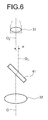
FIG. 6 is a view explaining a reason why an optical axis deviates. -
FIG. 7 is a conceptual perspective view of an inverted microscope according to a third embodiment of the present invention. -
FIG. 8 is an exploded perspective view of a structure of the inverted microscope shown inFIG. 7 . -
FIG. 9 is a conceptual perspective view of an inverted microscope according to a fourth embodiment of the present invention. - Exemplary embodiments of an inverted microscope according to the present invention will be explained in detail below with reference to the accompanying drawings. It should be noted that the present invention is not limited to the embodiments.
-
FIG. 1 is a conceptual perspective view of an inverted microscope according to a first embodiment of the present invention andFIG. 2 is a cross sectional view of an inner structure of the inverted microscope shown inFIG. 1 . - As shown in
FIGS. 1 and2 , the inverted microscope is a microscope that allows observing a sample as an observation target from underneath and is provided with a microscopemain body 1, astage 2 that is supported in the microscopemain body 1, and an observationoptical system 3 that allows observing a sample placed on thestage 2 from underneath. - The microscope
main body 1 has a box shape and is provided with abase part 1a that extends in a front-back direction, aback wall part 1b that extends upward from a back edge part of thebase part 1a, afront wall part 1c that extends upward from a front edge part of thebase part 1a, and abeam part 1d that connects an upper part of theback wall part 1b and an upper part of thefront wall part 1c together. An attachment area of anoptical device 4 is formed in a lower side area of thebeam part 1d and an attachment area of an objective lens 31 (seeFIG. 2 ) is formed in an upper side area thereof. - In an inner side of the
back wall part 1b and an inner side of thefront wall part 1c forming the attachment area, three pairs of fitting groves 1b1 and 1c1 provided at front and back sides are formed along the vertical direction. The fitting grooves 1b1 and 1c1 in pairs, to which aconvex part 4a which has a prismatic column shape and is provided in theoptical device 4 can be fitted, allow attaching theoptical device 4 and extend in the horizontal direction. The convexpart 4a provided in theoptical device 4 is guided to the fitting grooves 1b1 and 1c1 and theoptical device 4 is attached to the microscopemain body 1. The attachedoptical device 4 is then positioned by theconvex part 4a and the fitting grooves 1b1 and 1c1 and fixed. - As shown in
FIG. 2 , fitting holes 1b2 that are in communication with the respective three fitting grooves 1b1 are formed collaterally along the vertical direction in theback wall part 1b. The fitting hole 1b2, to which acolumnar convex part 5a provided in alight source 5 can be fitted, allows attaching thelight source 5. The convexpart 5a provided in thelight source 5 is guided to the fitting hole 1b2 and thelight source 5 is attached to the microscopemain body 1. The attachedlight source 5 is then positioned by the convexpart 5a and the fitting hole 1b2 and fixed. - On an upper surface of the
beam part 1d forming the attachment area, arevolver 6 and a focusingdevice 7 are attached. Therevolver 6, to which a plurality ofobjective lenses 31 can be attached, is capable of revolving and moving up and down. Then, one of theobjective lenses 31 attached to therevolver 6 is placed on the optical axis. The focusingdevice 7 serves to focus theobjective lens 31 on the sample and theobjective lens 31 attached to therevolver 6 is focused on the sample when therevolver 6 moves down in response to the operation of the focusingdevice 7. - As shown in
FIGS. 1 and2 , an upper surface 1b3 of theback wall part 1b and an upper surface 1c3 of thefront wall part 1c form the same planar surface running in the horizontal direction, and thestage 2 is attached over and supported by the upper surface 1b3 of theback wall part 1b and the upper surface 1c3 of thefront wall part 1c. - The
stage 2 has a plate like body whose upper surface and lower surface are flat and the sample is placed on the upper surface. Besides, an opening (open hole) 2a whose size is small enough not to allow the sample to drop therethrough is provided approximately at a center of thestage 2, enabling an observation light to pass through. - As shown in
FIG. 2 , the observationoptical system 3 enables observing the sample and is provided over the course from the microscopemain body 1 to a lens-barrel 8 attached to the microscopemain body 1. The observationoptical system 3 is provided with, other than theobjective lens 31 explained above, atube lens 32, amirror 33, arelay lens 34, atube lens 35, and aneyepiece 36. - The
tube lens 32, themirror 33, and therelay lens 34 are attached in an inside of the microscopemain body 1, and an observation light which becomes a parallel light beam by passing through theobjective lens 31 is made into an image by passing through thetube lens 32 and enters the lens-barrel 8 by way of themirror 33 and therelay lens 34. - The
tube lens 35 and theeyepiece 36 are attached in an inside of the lens-barrel 8, and an observation light having entered from the microscopemain body 1 is made into an image by passing through thetube lens 35 and observed when seen through theeyepiece 36. - The inverted microscope shown in
FIGS. 1 and2 is provided with atransmissive illumination device 9. Thetransmissive illumination device 9 is attached in an area above the microscopemain body 1. Thetransmissive illumination device 9 is provided with a supportingpost 91, alight source 92 attached to the supportingpost 91, afloodlight tube 93 attached to the supportingpost 91, and acondenser lens 94 attached to the supportingpost 91. - In the inverted microscope according to the first embodiment explained above, the
convex part 4a provided in theoptical device 4 is inserted to the fitting grooves 1b1 and 1c1 provided in the microscopemain body 1 in attaching theoptical device 4 in the attachment area. Theconvex part 4a provided in theoptical device 4 is guided to the fitting grooves 1b1 and 1c1 provided in the microscopemain body 1, and theoptical device 4 is attached to the microscopemain body 1. Then, the attachedoptical device 4 is positioned by theconvex part 4a and the fitting grooves 1b1 and 1c1 and fixed. - Next, a
convex part 5a provided in thelight source 5 is inserted to the fitting hole 1b2 provided in the microscopemain body 1. Theconvex part 5a provided in thelight source 5 is guided to the fitting hole 1b2 provided in the microscopemain body 1, and thelight source 5 is attached to the microscopemain body 1. Then, the attachedlight source 5 is positioned by theconvex part 5a and the fitting hole 1b2 and fixed. - The microscope
main body 1 of the inverted microscope according to the first embodiment explained above is provided with thebeam part 1d connecting the upper part of theback wall part 1b and the upper part of thefront wall part 1c, the attachment area of theoptical device 4 is formed in the lower side area of thebeam part 1d, and the attachment area of theobjective lens 31 is formed in the upper side area thereof. Since thebeam part 1d locates between thetube lens 32 and theobjective lens 31 and connects theback wall part 1b and thefront wall part 1c in pairs at the front and the back sides together, the microscopemain body 1 becomes of superiority in rigidity. Besides, since the focusingdevice 7 is arranged in the vicinity of thestage 2 irrespective of the number of attachedoptical devices 4, it is possible to reduce the size and be of superiority in rigidity. - While the
back wall part 1b and thefront wall part 1c are configured as supporting parts that support thestage 2 in the microscope main body according to the first embodiment explained above, the supporting parts are not limited to such wall bodies as theback wall part 1b and thefront wall part 1c and may be supporting posts (not shown) as long as they support thestage 2 in pairs at the front and the back sides. - While the focusing
device 7 is attached on the upper surface of thebeam part 1d, it is only necessary to attach at least a part of the focusingdevice 7 to thebeam part 1d or the stage supporting parts (theback wall part 1b or thefront wall part 1c). -
FIG. 3 is a conceptual perspective view of an inverted microscope according to a second embodiment of the present invention,FIG. 3-1 shows a state where an upper part structure is slid and adjusted forward, andFIG. 3-2 shows state where the upper part structure is slid and adjusted backward.FIG. 4 is a cross sectional view of an inner structure of the inverted microscope shown inFIG. 3 andFIG. 5 is an exploded perspective view of the structure of the inverted microscope shown inFIG. 3 . - The inverted microscope according to the second embodiment has no other difference from the inverted microscope according to the first embodiment than a configuration that the microscope
main body 1 is constituted by alower part structure 10 and anupper part structure 11. Therefore, the microscopemain body 1 will be explained, the same component as the inverted microscope according to the first embodiment will be assigned with the same reference sign, and the explanation of the same component will be omitted. - As shown in
FIG. 6 , when theoptical device 4 is attached between theobjective lens 31 and thetube lens 32 in the inverted microscope according to the first embodiment explained above, a light is refracted in passing through amirror 41 embedded in theoptical device 4 and an optical axis O deviates backward. Especially in a case where a plurality ofoptical devices 4 are attached between theobjective lens 31 and thetube lens 32 or a case where themirror 41 embedded in theoptical device 4 is thick, the optical axis O deviates backward significantly. - The inverted microscope according to the second embodiment is configured to enable an optical axis O2 of the
objective lens 31 to be slid and adjusted in the front-back direction so that an optical axis O1 of the attachedoptical device 4 and the optical axis O2 of theobjective lens 31 match (seeFIGS. 3-1 and3-2 ), and the microscopemain body 1 of the inverted microscope according to the second embodiment is constituted by the lower part structure (supporting part main body) 10 and the upper part structure (sliding body) 11 as explained above. - As shown in
FIGS. 3 and4 , thelower part structure 10 forms a lower part of the microscopemain body 1 and includes abase part 10a that extends in the front-back direction, a back walllower part 10b that extends upward from a back edge part of thebase part 10a, and a front walllower part 10c that extends upward from a front edge part of thebase part 10a. An upper surface 10b3 (seeFIG. 5 ) of the back walllower part 10b and an upper surface 10c3 (seeFIG. 5 ) of the front walllower part 10c form the same planar surface running in the horizontal direction, and theupper part structure 11 is attached over the upper surface 10b3 of the back walllower part 10b and the upper surface 10c3 of the front walllower part 10c. - The
upper part structure 11 forms an upper part of the microscopemain body 1 and is attached on top of thelower part structure 10. Theupper part structure 11 includes a back wallupper part 11b that extends upward from the back walllower part 10b of thelower part structure 10, a front wallupper part 11c that extends upward from the front walllower part 10c of thelower part structure 10 when attached to thelower part structure 10, and abeam part 11d that connects the back wallupper part 11b and the front wallupper part 11c approximately at a center in a height direction. An upper surface 11b3 of the back wallupper part 11b and an upper surface 11c3 of the front wallupper part 11c form the same planar surface running in the horizontal direction, and thestage 2 is attached over the upper surface 11b3 of the back wallupper part 11b and the upper surface 11c3 of the front wallupper part 11c. - As shown in
FIG. 5 , theupper part structure 11 explained above is fixed to thelower part structure 10 by tightening screws 12 (seeFIG. 8 ) inserted through long holes 11b4 and 11c4 (seeFIG. 8 ) provided in theupper part structure 11 with internal threads 10b4 and 10c4 provided in the lower part structure. Here, a click mechanism or an abutting surface for positioning (not shown) may be provided between thelower part structure 10 and theupper part structure 11 and theupper part structure 11 may be positioned at a predetermined position when nooptical device 4 is attached or depending on the number ofoptical devices 4. - The
revolver 6 and the focusingdevice 7 are attached on the upper surface of thebeam part 11d of theupper part structure 11. Therefore, when theupper part structure 11 is detached from thelower part structure 10, therevolver 6 and the focusingdevice 7 are detached together with theupper part structure 11. When thescrews 12 are loosened and the upper part structure is shifted with respect to thelower part structure 10, therevolver 6 and the focusingdevice 7 are shifted together with theupper part structure 11. - The
transmissive illumination device 9 is attached to the back wallupper part 11b of theupper part structure 11. Therefore, when theupper part structure 11 is detached from thelower part structure 10, thetransmissive illumination device 9 is detached together with theupper part structure 11. When thescrews 12 are loosened and the upper part structure is shifted with respect to thelower part structure 10, thetransmissive illumination device 9 is shifted together with theupper part structure 11. - In making an adjustment so that the optical axis O1 of the attached
optical device 4 and the optical axis O2 of theobjective lens 31 match in the inverted microscope according to the embodiment explained above, the screws fixing theupper part structure 11 to thelower part structure 10 are loosened and theupper part structure 11 is shifted so that the optical axis O1 of the attachedoptical device 4 and the optical axis O2 of theobjective lens 31 match (seeFIGS. 3-1 and3-2 ). After that, theupper part structure 11 is fixed to thelower part structure 10 by tightening the screws. - Since the microscope
main body 1 of the inverted microscope according to the second embodiment explained above is provided with thelower part structure 10 and theupper part structure 11 attached to thelower part structure 10, and theupper part structure 11 can be shifted with respect to thelower part structure 10, it is possible to make an adjustment so that the optical axis O1 of theoptical device 4 attached to thelower part structure 10 and the optical axis O2 of theobjective lens 31 attached to therevolver 6 match. - Since the
revolver 6 and the focusingdevice 7 are attached to the upper surface of thebeam part 11d of theupper part structure 11 and also thetransmissive illumination device 9 is attached to the back wallupper part 11b of theupper part structure 11, no deviation would be generated, even when theupper part structure 11 is shifted with respect to thelower part structure 10, between the optical axis of thetransmissive illumination device 9 and the optical axis of theobjective lens 31 attached to therevolver 6 by making the adjustment so that the optical axis of thetransmissive illumination device 9 and the optical axis of theobjective lens 31 attached to therevolver 6 match, enabling in a highly reliable measurement. -
FIG. 7 is a conceptual perspective view of an inverted microscope according to an embodiment of the present invention andFIG. 8 is an exploded perspective view of a structure of the inverted microscope shown inFIG. 7 . - The inverted microscope according to the third embodiment has no other difference from the inverted microscope according to the second embodiment than a configuration that edge parts 11d1 and 11d2 are provided on the upper surface of the
beam part 11d. Therefore, thebeam part 11d will be explained, the same component as the second embodiment will be assigned with the same reference sign, and the explanation of the same component will be omitted. - The inverted microscope tends to be contaminated in a lower side area of the
stage 2 due to a dripping of oil used for an oil immersion objective lens, solvent dissolving the sample, liquid used for managing temperature or humidity, and the like from thestage 2. - The
beam part 11d of the inverted microscope according to the third embodiment has a size to cover an entire area of the upper surface of the attachedoptical device 4 and receives once the oil, the solvent, the liquid, and the like dripping from thestage 2 by the upper surface. Besides, an edge part 11d1 protruding upward is formed at both edge parts on the upper surface of thebeam part 11d and surrounds an outer periphery of the upper surface of thebeam part 11d together with the back wallupper part 11b and the front wallupper part 11c. Around the open hole through which an observation light is transmitted, an edge part 11d2 protruding upward is formed and surrounds the open hole. These edge parts 11d1 and 11d2 prevent the oil, the solvent, the liquid, and the like received by the upper surface of thebeam part 11d once from irregularly running down from an edge part at the upper surface side of thebeam part 11d. Besides, a cutout 11d3 is provided at a part of the edge part 11d1 and allows the oil, the solvent, the liquid, and the like collected on the upper surface of thebeam part 11d to run out to the outside from the cutout 11d3. - Since the
beam part 11d of the inverted microscope according to the third embodiment covers an entire area of the upper surface of the attachedoptical device 4 and the dripping of the oil, the solvent, the liquid, and the like from thestage 2 is received by thebeam part 11d, it is possible to prevent a contamination of the attachedoptical device 4. In addition, since the received oil, solvent, liquid, and the like are run out from the cutout 11d3 provided in the outer periphery of the upper surface of thebeam part 11d, there is no chance of leaking from the edge parts 11d1 and 11d2 and contaminating the attachedoptical device 4. -
FIG. 9 is a conceptual perspective view of an inverted microscope according to a fourth embodiment of the present invention. The inverted microscope according to the fourth embodiment has no other difference from the inverted microscope according to the second embodiment than a configuration that the focusingdevice 7 is configured by anautofocusing device 70. Therefore, the same component as the inverted microscope according to the second embodiment will be assigned with the same reference sign and the explanation of the same component will be omitted. - As shown in
FIG. 9 , the focusingdevice 7 is configured by theautofocusing device 70 in the inverted microscope according to the fourth embodiment of the present invention. Theautofocusing device 70 automatically focuses theobjective lens 31 and is provided with a light source, a lens, and an optical receiver. The autofocusing device is, for example, adopts an active method, detects a reflection light from the sample placed on the stage or from a bottom surface of a sample container, and automatically focuses theobjective lens 31. - Since the focusing
device 7 is configured by theautofocusing device 70 in the inverted microscope according to the fourth embodiment, theobjective lens 31 is automatically focused and a focusing operation becomes easy. Reference Signs List -
- 1
- MICROSCOPE MAIN BODY
- 1a
- BASE PART
- 1b
- BACK WALL PART
- 1b1
- FITTING GROOVE
- 1b2
- FITTING HOLE
- 1b3
- UPPER SURFACE
- 1c
- FRONT WALL PART
- 1c1
- FITTING GROOVE
- 1c3
- UPPER SURFACE
- 1d
- BEAM PART
- 10
- LOWER PART STRUCTURE
- 10a
- BASE PART
- 10b
- BACK WALL LOWER PART
- 10b4
- INTERNAL THREAD
- 10c
- FRONT WALL LOWER PART
- 11
- UPPER PART STRUCTURE
- 11b
- BACK WALL UPPER PART
- 11b4
- LONG HOLE
- 11c
- FRONT WALL UPPER PART
- 11c4
- LONG HOLE
- 11d
- BEAM PART
- 11d1
- EDGE PART
- 11d2
- EDGE PART
- 11d3
- CUTOUT
- 2
- STAGE
- 3
- OBSERVATION OPTICAL SYSTEM
- 31
- OBJECTIVE LENS
- 32
- TUBE LENS
- 36
- EYEPIECE
- 4
- OPTICAL DEVICE
- 4a
- CONVEX PART
- 41
- MIRROR
- 5
- LIGHT SOURCE
- 5a
- CONVEX PART
- 6
- REVOLVER
- 7
- FOCUSING DEVICE
- 70
- AUTOFOCUSING DEVICE
- 8
- LENS-BARREL
- 9
- TRANSMISSIVE ILLUMINATION DEVICE
Claims (7)
- An inverted microscope provided with a microscope main body, a stage that is supported by the microscope main body, and an observation optical system that allows observing a sample placed on the stage from underneath, wherein
the microscope main body, in which an optical device can be attached between an objective lens and a tube lens which constitute the observation optical system includesa plurality of stage supporting parts that support the stage; anda beam part that connects, in a manner of locating between the tube lens and the objective lens, at least a pair of stage supporting parts at front and back sides together among the plurality of stage supporting parts. - The inverted microscope according to claim 1, comprising a focusing device at least a part of which is attached to one of the stage supporting parts and the beam part, and which shifts the objective lens to an optical axis direction.
- The inverted microscope according to claim 2, wherein the focusing device is an autofocusing device that detects a reflection light from one of the sample and a sample container and focuses the objective lens.
- The inverted microscope according to any one of claims 1 to 3, wherein the stage supporting parts includes
a supporting part main body; and
a sliding body that is formed together with the beam part and attached to the supporting part main body in a manner enabling a sliding adjustment so that an optical axis of the attached optical device and an optical axis of the objective lens match. - The inverted microscope according to any one of claims 1 to 4, wherein the beam part has a size to cover an entire area of an upper surface of the attached optical device and has an edge part protruding upward in at least a part of an outer periphery of the upper surface.
- The inverted microscope according to any one of claims 1 to 3, wherein the microscope main body includes
a lower part structure to which the tube lens is attached and the optical device is configured to be attached; and
an upper part structure in which the plurality of stage supporting parts and the beam part are integrally formed and which is attached to the lower part structure in a manner enabling a sliding adjustment so that an optical axis of the attached optical device and an optical axis of the objective lens match. - The inverted microscope according to claim 6, wherein the beam part has a size to cover an entire area of an upper surface of the attached optical device and has an edge part protruding upward in at least a part of an outer periphery of the upper surface.
Applications Claiming Priority (2)
| Application Number | Priority Date | Filing Date | Title |
|---|---|---|---|
| JP2010123440A JP5586326B2 (en) | 2010-05-28 | 2010-05-28 | Inverted microscope |
| PCT/JP2011/062287 WO2011149090A1 (en) | 2010-05-28 | 2011-05-27 | Inverted microscope |
Publications (3)
| Publication Number | Publication Date |
|---|---|
| EP2579086A1 true EP2579086A1 (en) | 2013-04-10 |
| EP2579086A4 EP2579086A4 (en) | 2017-04-26 |
| EP2579086B1 EP2579086B1 (en) | 2021-07-07 |
Family
ID=45004072
Family Applications (1)
| Application Number | Title | Priority Date | Filing Date |
|---|---|---|---|
| EP11786787.9A Active EP2579086B1 (en) | 2010-05-28 | 2011-05-27 | Inverted microscope |
Country Status (4)
| Country | Link |
|---|---|
| US (1) | US8749883B2 (en) |
| EP (1) | EP2579086B1 (en) |
| JP (1) | JP5586326B2 (en) |
| WO (1) | WO2011149090A1 (en) |
Cited By (2)
| Publication number | Priority date | Publication date | Assignee | Title |
|---|---|---|---|---|
| EP2645145A1 (en) * | 2012-03-30 | 2013-10-02 | Olympus Corporation | Inverted microscope |
| EP3528028A4 (en) * | 2016-10-14 | 2020-07-22 | Nikon Corporation | MICROSCOPE DEVICE AND LENS UNIT |
Families Citing this family (8)
| Publication number | Priority date | Publication date | Assignee | Title |
|---|---|---|---|---|
| JP5926936B2 (en) * | 2011-11-28 | 2016-05-25 | オリンパス株式会社 | microscope |
| JP6032916B2 (en) * | 2012-03-29 | 2016-11-30 | オリンパス株式会社 | Inverted microscope |
| JP6168727B2 (en) * | 2012-03-29 | 2017-07-26 | オリンパス株式会社 | Inverted microscope |
| JP2013231855A (en) * | 2012-04-27 | 2013-11-14 | Olympus Corp | Inverted microscope |
| JP2014006395A (en) * | 2012-06-25 | 2014-01-16 | Olympus Corp | Microscope and temperature retaining member |
| JP6133571B2 (en) * | 2012-10-30 | 2017-05-24 | 株式会社ジンズ | Transmitted light observation device |
| WO2016145393A1 (en) | 2015-03-12 | 2016-09-15 | Purdue Research Foundation | Biodynamic microscopes and methods of use thereof |
| WO2025144943A1 (en) * | 2023-12-27 | 2025-07-03 | Idexx Laboratories, Inc. | Microscopy assemblies |
Family Cites Families (20)
| Publication number | Priority date | Publication date | Assignee | Title |
|---|---|---|---|---|
| DE3037556A1 (en) * | 1980-10-01 | 1982-05-27 | Le Materiel Biomedical, Paris | Microscope with observation and illumination assemblies - which are alternately positionable above or below object stage in recess of main frame |
| DE3938412A1 (en) * | 1989-11-18 | 1991-05-23 | Zeiss Carl Fa | MICROSCOPE WITH A DIAGONAL OBSERVATION BEAM |
| DE4404286C2 (en) * | 1994-02-11 | 1996-01-25 | Leica Mikroskopie & Syst | Fluorescence device for an inverse microscope |
| JP3670316B2 (en) * | 1994-08-03 | 2005-07-13 | オリンパス株式会社 | Inverted microscope |
| JP3885305B2 (en) * | 1997-08-27 | 2007-02-21 | 株式会社ニコン | Inverted microscope |
| JPH11344675A (en) * | 1998-05-29 | 1999-12-14 | Nikon Corp | Inverted microscope |
| JP4933706B2 (en) | 2000-09-22 | 2012-05-16 | オリンパス株式会社 | microscope |
| US20030107800A1 (en) * | 2000-10-06 | 2003-06-12 | Gerhard Doering | System and method for controlling and/or displaying microscope functions |
| DE10050823A1 (en) * | 2000-10-06 | 2002-04-18 | Zeiss Carl Jena Gmbh | Microscope, especially inverted microscope |
| JP2002267940A (en) * | 2001-03-09 | 2002-09-18 | Olympus Optical Co Ltd | Inverted microscope system |
| JP2002303795A (en) * | 2001-04-04 | 2002-10-18 | Olympus Optical Co Ltd | Inverted microscope |
| US6791767B2 (en) * | 2002-09-16 | 2004-09-14 | Leica Microsystems, Inc. | Magnetic optical element holder and microscope assembly including same |
| DE20219371U1 (en) * | 2002-12-13 | 2003-02-20 | Leica Mikroskopie und Systeme GmbH, 35578 Wetzlar | Inverse microscope with bino photo tube |
| DE10352523A1 (en) * | 2003-11-07 | 2005-06-09 | Carl Zeiss Jena Gmbh | Invertible light microscope |
| JP2006091571A (en) * | 2004-09-24 | 2006-04-06 | Olympus Corp | Inverted microscope |
| JP2006091723A (en) * | 2004-09-27 | 2006-04-06 | Olympus Corp | Inverted microscope |
| CN100526453C (en) * | 2005-05-20 | 2009-08-12 | 麦克奥迪实业集团有限公司 | Cell collection method after laser microdissection |
| WO2007137598A1 (en) * | 2006-05-26 | 2007-12-06 | Leica Microsystems Cms Gmbh | Inverse microscope |
| JP5173270B2 (en) * | 2007-06-11 | 2013-04-03 | オリンパス株式会社 | Inverted microscope |
| EP2175302B1 (en) * | 2007-08-07 | 2018-09-19 | Nikon Corporation | Microscope |
-
2010
- 2010-05-28 JP JP2010123440A patent/JP5586326B2/en active Active
-
2011
- 2011-05-27 EP EP11786787.9A patent/EP2579086B1/en active Active
- 2011-05-27 WO PCT/JP2011/062287 patent/WO2011149090A1/en not_active Ceased
-
2012
- 2012-11-21 US US13/683,237 patent/US8749883B2/en active Active
Cited By (4)
| Publication number | Priority date | Publication date | Assignee | Title |
|---|---|---|---|---|
| EP2645145A1 (en) * | 2012-03-30 | 2013-10-02 | Olympus Corporation | Inverted microscope |
| US9494780B2 (en) | 2012-03-30 | 2016-11-15 | Olympus Corporation | Inverted microscope |
| EP3528028A4 (en) * | 2016-10-14 | 2020-07-22 | Nikon Corporation | MICROSCOPE DEVICE AND LENS UNIT |
| US11249296B2 (en) | 2016-10-14 | 2022-02-15 | Nikon Corporation | Microscope apparatus and objective lens unit |
Also Published As
| Publication number | Publication date |
|---|---|
| EP2579086A4 (en) | 2017-04-26 |
| EP2579086B1 (en) | 2021-07-07 |
| US20130075578A1 (en) | 2013-03-28 |
| US8749883B2 (en) | 2014-06-10 |
| JP5586326B2 (en) | 2014-09-10 |
| JP2011248245A (en) | 2011-12-08 |
| WO2011149090A1 (en) | 2011-12-01 |
Similar Documents
| Publication | Publication Date | Title |
|---|---|---|
| EP2579086B1 (en) | Inverted microscope | |
| US7327514B2 (en) | Microscope system comprising actuator element for moving the objective lens for focussing | |
| JP3885305B2 (en) | Inverted microscope | |
| KR101825217B1 (en) | Device for observing microstructure using mobile phone camera | |
| JP3365791B2 (en) | System microscope | |
| TWI484238B (en) | Immersion lens support device | |
| EP1956408B1 (en) | Microscope Iens barrel | |
| JP2015029461A (en) | Imaging device | |
| JPH0843741A (en) | Inverted microscope | |
| US20100091363A1 (en) | Objective lens, nosepiece and inverted microscope equipped therewith | |
| JP6604774B2 (en) | microscope | |
| EP2594982B1 (en) | Microscope system | |
| US9250433B2 (en) | Microscope system with plural attachable/detachable objective lens units | |
| JPH1138326A (en) | Inverted microscope | |
| KR20180109420A (en) | Illumination guide, lens module with the same, and device for observing subject using mobile phone camera with the lens module | |
| US9140886B2 (en) | Inverted microscope including a control unit configured to synchronize a switching operation between absorption filters with a switching operation between excitation filters | |
| JP5988629B2 (en) | Microscope with multiple optical units | |
| JP6203102B2 (en) | Inverted microscope device | |
| JP4928638B2 (en) | microscope | |
| JP2017072731A (en) | Sample holder | |
| JP2001083430A (en) | Inverted microscope device | |
| JP6032916B2 (en) | Inverted microscope | |
| JP4819989B2 (en) | microscope | |
| JP6618320B2 (en) | Microscope stage, mechanical stage and microscope | |
| JP5911354B2 (en) | Inverted microscope |
Legal Events
| Date | Code | Title | Description |
|---|---|---|---|
| PUAI | Public reference made under article 153(3) epc to a published international application that has entered the european phase |
Free format text: ORIGINAL CODE: 0009012 |
|
| 17P | Request for examination filed |
Effective date: 20121126 |
|
| AK | Designated contracting states |
Kind code of ref document: A1 Designated state(s): AL AT BE BG CH CY CZ DE DK EE ES FI FR GB GR HR HU IE IS IT LI LT LU LV MC MK MT NL NO PL PT RO RS SE SI SK SM TR |
|
| DAX | Request for extension of the european patent (deleted) | ||
| RAP1 | Party data changed (applicant data changed or rights of an application transferred) |
Owner name: OLYMPUS CORPORATION |
|
| RAP1 | Party data changed (applicant data changed or rights of an application transferred) |
Owner name: OLYMPUS CORPORATION |
|
| RAP1 | Party data changed (applicant data changed or rights of an application transferred) |
Owner name: OLYMPUS CORPORATION |
|
| RIN1 | Information on inventor provided before grant (corrected) |
Inventor name: KITAHARA, AKIHIRO |
|
| RA4 | Supplementary search report drawn up and despatched (corrected) |
Effective date: 20170329 |
|
| RIC1 | Information provided on ipc code assigned before grant |
Ipc: G02B 21/24 20060101AFI20170323BHEP |
|
| GRAP | Despatch of communication of intention to grant a patent |
Free format text: ORIGINAL CODE: EPIDOSNIGR1 |
|
| STAA | Information on the status of an ep patent application or granted ep patent |
Free format text: STATUS: GRANT OF PATENT IS INTENDED |
|
| INTG | Intention to grant announced |
Effective date: 20201214 |
|
| GRAJ | Information related to disapproval of communication of intention to grant by the applicant or resumption of examination proceedings by the epo deleted |
Free format text: ORIGINAL CODE: EPIDOSDIGR1 |
|
| STAA | Information on the status of an ep patent application or granted ep patent |
Free format text: STATUS: REQUEST FOR EXAMINATION WAS MADE |
|
| GRAS | Grant fee paid |
Free format text: ORIGINAL CODE: EPIDOSNIGR3 |
|
| STAA | Information on the status of an ep patent application or granted ep patent |
Free format text: STATUS: GRANT OF PATENT IS INTENDED |
|
| INTC | Intention to grant announced (deleted) | ||
| GRAP | Despatch of communication of intention to grant a patent |
Free format text: ORIGINAL CODE: EPIDOSNIGR1 |
|
| GRAA | (expected) grant |
Free format text: ORIGINAL CODE: 0009210 |
|
| STAA | Information on the status of an ep patent application or granted ep patent |
Free format text: STATUS: THE PATENT HAS BEEN GRANTED |
|
| INTG | Intention to grant announced |
Effective date: 20210527 |
|
| REG | Reference to a national code |
Ref country code: DE Ref legal event code: R082 Ref document number: 602011071330 Country of ref document: DE Representative=s name: WUESTHOFF & WUESTHOFF, PATENTANWAELTE PARTG MB, DE |
|
| AK | Designated contracting states |
Kind code of ref document: B1 Designated state(s): AL AT BE BG CH CY CZ DE DK EE ES FI FR GB GR HR HU IE IS IT LI LT LU LV MC MK MT NL NO PL PT RO RS SE SI SK SM TR |
|
| REG | Reference to a national code |
Ref country code: GB Ref legal event code: FG4D |
|
| REG | Reference to a national code |
Ref country code: AT Ref legal event code: REF Ref document number: 1409150 Country of ref document: AT Kind code of ref document: T Effective date: 20210715 |
|
| REG | Reference to a national code |
Ref country code: DE Ref legal event code: R096 Ref document number: 602011071330 Country of ref document: DE |
|
| REG | Reference to a national code |
Ref country code: IE Ref legal event code: FG4D |
|
| REG | Reference to a national code |
Ref country code: LT Ref legal event code: MG9D |
|
| REG | Reference to a national code |
Ref country code: NL Ref legal event code: MP Effective date: 20210707 |
|
| REG | Reference to a national code |
Ref country code: AT Ref legal event code: MK05 Ref document number: 1409150 Country of ref document: AT Kind code of ref document: T Effective date: 20210707 |
|
| PG25 | Lapsed in a contracting state [announced via postgrant information from national office to epo] |
Ref country code: SE Free format text: LAPSE BECAUSE OF FAILURE TO SUBMIT A TRANSLATION OF THE DESCRIPTION OR TO PAY THE FEE WITHIN THE PRESCRIBED TIME-LIMIT Effective date: 20210707 Ref country code: HR Free format text: LAPSE BECAUSE OF FAILURE TO SUBMIT A TRANSLATION OF THE DESCRIPTION OR TO PAY THE FEE WITHIN THE PRESCRIBED TIME-LIMIT Effective date: 20210707 Ref country code: PT Free format text: LAPSE BECAUSE OF FAILURE TO SUBMIT A TRANSLATION OF THE DESCRIPTION OR TO PAY THE FEE WITHIN THE PRESCRIBED TIME-LIMIT Effective date: 20211108 Ref country code: NL Free format text: LAPSE BECAUSE OF FAILURE TO SUBMIT A TRANSLATION OF THE DESCRIPTION OR TO PAY THE FEE WITHIN THE PRESCRIBED TIME-LIMIT Effective date: 20210707 Ref country code: RS Free format text: LAPSE BECAUSE OF FAILURE TO SUBMIT A TRANSLATION OF THE DESCRIPTION OR TO PAY THE FEE WITHIN THE PRESCRIBED TIME-LIMIT Effective date: 20210707 Ref country code: NO Free format text: LAPSE BECAUSE OF FAILURE TO SUBMIT A TRANSLATION OF THE DESCRIPTION OR TO PAY THE FEE WITHIN THE PRESCRIBED TIME-LIMIT Effective date: 20211007 Ref country code: FI Free format text: LAPSE BECAUSE OF FAILURE TO SUBMIT A TRANSLATION OF THE DESCRIPTION OR TO PAY THE FEE WITHIN THE PRESCRIBED TIME-LIMIT Effective date: 20210707 Ref country code: ES Free format text: LAPSE BECAUSE OF FAILURE TO SUBMIT A TRANSLATION OF THE DESCRIPTION OR TO PAY THE FEE WITHIN THE PRESCRIBED TIME-LIMIT Effective date: 20210707 Ref country code: LT Free format text: LAPSE BECAUSE OF FAILURE TO SUBMIT A TRANSLATION OF THE DESCRIPTION OR TO PAY THE FEE WITHIN THE PRESCRIBED TIME-LIMIT Effective date: 20210707 Ref country code: AT Free format text: LAPSE BECAUSE OF FAILURE TO SUBMIT A TRANSLATION OF THE DESCRIPTION OR TO PAY THE FEE WITHIN THE PRESCRIBED TIME-LIMIT Effective date: 20210707 Ref country code: BG Free format text: LAPSE BECAUSE OF FAILURE TO SUBMIT A TRANSLATION OF THE DESCRIPTION OR TO PAY THE FEE WITHIN THE PRESCRIBED TIME-LIMIT Effective date: 20211007 |
|
| PG25 | Lapsed in a contracting state [announced via postgrant information from national office to epo] |
Ref country code: PL Free format text: LAPSE BECAUSE OF FAILURE TO SUBMIT A TRANSLATION OF THE DESCRIPTION OR TO PAY THE FEE WITHIN THE PRESCRIBED TIME-LIMIT Effective date: 20210707 Ref country code: LV Free format text: LAPSE BECAUSE OF FAILURE TO SUBMIT A TRANSLATION OF THE DESCRIPTION OR TO PAY THE FEE WITHIN THE PRESCRIBED TIME-LIMIT Effective date: 20210707 Ref country code: GR Free format text: LAPSE BECAUSE OF FAILURE TO SUBMIT A TRANSLATION OF THE DESCRIPTION OR TO PAY THE FEE WITHIN THE PRESCRIBED TIME-LIMIT Effective date: 20211008 |
|
| REG | Reference to a national code |
Ref country code: DE Ref legal event code: R097 Ref document number: 602011071330 Country of ref document: DE |
|
| PG25 | Lapsed in a contracting state [announced via postgrant information from national office to epo] |
Ref country code: DK Free format text: LAPSE BECAUSE OF FAILURE TO SUBMIT A TRANSLATION OF THE DESCRIPTION OR TO PAY THE FEE WITHIN THE PRESCRIBED TIME-LIMIT Effective date: 20210707 |
|
| PLBE | No opposition filed within time limit |
Free format text: ORIGINAL CODE: 0009261 |
|
| STAA | Information on the status of an ep patent application or granted ep patent |
Free format text: STATUS: NO OPPOSITION FILED WITHIN TIME LIMIT |
|
| PG25 | Lapsed in a contracting state [announced via postgrant information from national office to epo] |
Ref country code: SM Free format text: LAPSE BECAUSE OF FAILURE TO SUBMIT A TRANSLATION OF THE DESCRIPTION OR TO PAY THE FEE WITHIN THE PRESCRIBED TIME-LIMIT Effective date: 20210707 Ref country code: SK Free format text: LAPSE BECAUSE OF FAILURE TO SUBMIT A TRANSLATION OF THE DESCRIPTION OR TO PAY THE FEE WITHIN THE PRESCRIBED TIME-LIMIT Effective date: 20210707 Ref country code: RO Free format text: LAPSE BECAUSE OF FAILURE TO SUBMIT A TRANSLATION OF THE DESCRIPTION OR TO PAY THE FEE WITHIN THE PRESCRIBED TIME-LIMIT Effective date: 20210707 Ref country code: EE Free format text: LAPSE BECAUSE OF FAILURE TO SUBMIT A TRANSLATION OF THE DESCRIPTION OR TO PAY THE FEE WITHIN THE PRESCRIBED TIME-LIMIT Effective date: 20210707 Ref country code: CZ Free format text: LAPSE BECAUSE OF FAILURE TO SUBMIT A TRANSLATION OF THE DESCRIPTION OR TO PAY THE FEE WITHIN THE PRESCRIBED TIME-LIMIT Effective date: 20210707 Ref country code: AL Free format text: LAPSE BECAUSE OF FAILURE TO SUBMIT A TRANSLATION OF THE DESCRIPTION OR TO PAY THE FEE WITHIN THE PRESCRIBED TIME-LIMIT Effective date: 20210707 |
|
| 26N | No opposition filed |
Effective date: 20220408 |
|
| PG25 | Lapsed in a contracting state [announced via postgrant information from national office to epo] |
Ref country code: IT Free format text: LAPSE BECAUSE OF FAILURE TO SUBMIT A TRANSLATION OF THE DESCRIPTION OR TO PAY THE FEE WITHIN THE PRESCRIBED TIME-LIMIT Effective date: 20210707 |
|
| REG | Reference to a national code |
Ref country code: CH Ref legal event code: PL |
|
| REG | Reference to a national code |
Ref country code: DE Ref legal event code: R081 Ref document number: 602011071330 Country of ref document: DE Owner name: EVIDENT CORPORATION, JP Free format text: FORMER OWNER: OLYMPUS CORPORATION, TOKYO, JP |
|
| REG | Reference to a national code |
Ref country code: BE Ref legal event code: MM Effective date: 20220531 |
|
| GBPC | Gb: european patent ceased through non-payment of renewal fee |
Effective date: 20220527 |
|
| PG25 | Lapsed in a contracting state [announced via postgrant information from national office to epo] |
Ref country code: MC Free format text: LAPSE BECAUSE OF FAILURE TO SUBMIT A TRANSLATION OF THE DESCRIPTION OR TO PAY THE FEE WITHIN THE PRESCRIBED TIME-LIMIT Effective date: 20210707 Ref country code: LU Free format text: LAPSE BECAUSE OF NON-PAYMENT OF DUE FEES Effective date: 20220527 Ref country code: LI Free format text: LAPSE BECAUSE OF NON-PAYMENT OF DUE FEES Effective date: 20220531 Ref country code: CH Free format text: LAPSE BECAUSE OF NON-PAYMENT OF DUE FEES Effective date: 20220531 |
|
| PG25 | Lapsed in a contracting state [announced via postgrant information from national office to epo] |
Ref country code: IE Free format text: LAPSE BECAUSE OF NON-PAYMENT OF DUE FEES Effective date: 20220527 Ref country code: FR Free format text: LAPSE BECAUSE OF NON-PAYMENT OF DUE FEES Effective date: 20220531 |
|
| PG25 | Lapsed in a contracting state [announced via postgrant information from national office to epo] |
Ref country code: GB Free format text: LAPSE BECAUSE OF NON-PAYMENT OF DUE FEES Effective date: 20220527 Ref country code: BE Free format text: LAPSE BECAUSE OF NON-PAYMENT OF DUE FEES Effective date: 20220531 |
|
| PG25 | Lapsed in a contracting state [announced via postgrant information from national office to epo] |
Ref country code: HU Free format text: LAPSE BECAUSE OF FAILURE TO SUBMIT A TRANSLATION OF THE DESCRIPTION OR TO PAY THE FEE WITHIN THE PRESCRIBED TIME-LIMIT; INVALID AB INITIO Effective date: 20110527 |
|
| PG25 | Lapsed in a contracting state [announced via postgrant information from national office to epo] |
Ref country code: MK Free format text: LAPSE BECAUSE OF FAILURE TO SUBMIT A TRANSLATION OF THE DESCRIPTION OR TO PAY THE FEE WITHIN THE PRESCRIBED TIME-LIMIT Effective date: 20210707 Ref country code: CY Free format text: LAPSE BECAUSE OF FAILURE TO SUBMIT A TRANSLATION OF THE DESCRIPTION OR TO PAY THE FEE WITHIN THE PRESCRIBED TIME-LIMIT Effective date: 20210707 |
|
| PG25 | Lapsed in a contracting state [announced via postgrant information from national office to epo] |
Ref country code: MT Free format text: LAPSE BECAUSE OF FAILURE TO SUBMIT A TRANSLATION OF THE DESCRIPTION OR TO PAY THE FEE WITHIN THE PRESCRIBED TIME-LIMIT Effective date: 20210707 |
|
| PGFP | Annual fee paid to national office [announced via postgrant information from national office to epo] |
Ref country code: DE Payment date: 20250402 Year of fee payment: 15 |
|
| PG25 | Lapsed in a contracting state [announced via postgrant information from national office to epo] |
Ref country code: TR Free format text: LAPSE BECAUSE OF FAILURE TO SUBMIT A TRANSLATION OF THE DESCRIPTION OR TO PAY THE FEE WITHIN THE PRESCRIBED TIME-LIMIT Effective date: 20210707 |