EP2578954B1 - Vorrichtung zur Kühlung von Raumluft - Google Patents
Vorrichtung zur Kühlung von Raumluft Download PDFInfo
- Publication number
- EP2578954B1 EP2578954B1 EP12186510.9A EP12186510A EP2578954B1 EP 2578954 B1 EP2578954 B1 EP 2578954B1 EP 12186510 A EP12186510 A EP 12186510A EP 2578954 B1 EP2578954 B1 EP 2578954B1
- Authority
- EP
- European Patent Office
- Prior art keywords
- pipe
- water
- ventilator
- cooling
- air
- Prior art date
- Legal status (The legal status is an assumption and is not a legal conclusion. Google has not performed a legal analysis and makes no representation as to the accuracy of the status listed.)
- Active
Links
Images

Classifications
-
- F—MECHANICAL ENGINEERING; LIGHTING; HEATING; WEAPONS; BLASTING
- F24—HEATING; RANGES; VENTILATING
- F24F—AIR-CONDITIONING; AIR-HUMIDIFICATION; VENTILATION; USE OF AIR CURRENTS FOR SCREENING
- F24F3/00—Air-conditioning systems in which conditioned primary air is supplied from one or more central stations to distributing units in the rooms or spaces where it may receive secondary treatment; Apparatus specially designed for such systems
- F24F3/06—Air-conditioning systems in which conditioned primary air is supplied from one or more central stations to distributing units in the rooms or spaces where it may receive secondary treatment; Apparatus specially designed for such systems characterised by the arrangements for the supply of heat-exchange fluid for the subsequent treatment of primary air in the room units
-
- F—MECHANICAL ENGINEERING; LIGHTING; HEATING; WEAPONS; BLASTING
- F24—HEATING; RANGES; VENTILATING
- F24F—AIR-CONDITIONING; AIR-HUMIDIFICATION; VENTILATION; USE OF AIR CURRENTS FOR SCREENING
- F24F12/00—Use of energy recovery systems in air conditioning, ventilation or screening
- F24F12/001—Use of energy recovery systems in air conditioning, ventilation or screening with heat-exchange between supplied and exhausted air
- F24F12/002—Use of energy recovery systems in air conditioning, ventilation or screening with heat-exchange between supplied and exhausted air using an intermediate heat-transfer fluid
-
- F—MECHANICAL ENGINEERING; LIGHTING; HEATING; WEAPONS; BLASTING
- F24—HEATING; RANGES; VENTILATING
- F24F—AIR-CONDITIONING; AIR-HUMIDIFICATION; VENTILATION; USE OF AIR CURRENTS FOR SCREENING
- F24F5/00—Air-conditioning systems or apparatus not covered by F24F1/00 or F24F3/00, e.g. using solar heat or combined with household units such as an oven or water heater
- F24F5/0003—Exclusively-fluid systems
-
- F—MECHANICAL ENGINEERING; LIGHTING; HEATING; WEAPONS; BLASTING
- F24—HEATING; RANGES; VENTILATING
- F24F—AIR-CONDITIONING; AIR-HUMIDIFICATION; VENTILATION; USE OF AIR CURRENTS FOR SCREENING
- F24F5/00—Air-conditioning systems or apparatus not covered by F24F1/00 or F24F3/00, e.g. using solar heat or combined with household units such as an oven or water heater
- F24F5/0007—Air-conditioning systems or apparatus not covered by F24F1/00 or F24F3/00, e.g. using solar heat or combined with household units such as an oven or water heater cooling apparatus specially adapted for use in air-conditioning
- F24F5/0035—Air-conditioning systems or apparatus not covered by F24F1/00 or F24F3/00, e.g. using solar heat or combined with household units such as an oven or water heater cooling apparatus specially adapted for use in air-conditioning using evaporation
-
- Y—GENERAL TAGGING OF NEW TECHNOLOGICAL DEVELOPMENTS; GENERAL TAGGING OF CROSS-SECTIONAL TECHNOLOGIES SPANNING OVER SEVERAL SECTIONS OF THE IPC; TECHNICAL SUBJECTS COVERED BY FORMER USPC CROSS-REFERENCE ART COLLECTIONS [XRACs] AND DIGESTS
- Y02—TECHNOLOGIES OR APPLICATIONS FOR MITIGATION OR ADAPTATION AGAINST CLIMATE CHANGE
- Y02B—CLIMATE CHANGE MITIGATION TECHNOLOGIES RELATED TO BUILDINGS, e.g. HOUSING, HOUSE APPLIANCES OR RELATED END-USER APPLICATIONS
- Y02B30/00—Energy efficient heating, ventilation or air conditioning [HVAC]
- Y02B30/54—Free-cooling systems
-
- Y—GENERAL TAGGING OF NEW TECHNOLOGICAL DEVELOPMENTS; GENERAL TAGGING OF CROSS-SECTIONAL TECHNOLOGIES SPANNING OVER SEVERAL SECTIONS OF THE IPC; TECHNICAL SUBJECTS COVERED BY FORMER USPC CROSS-REFERENCE ART COLLECTIONS [XRACs] AND DIGESTS
- Y02—TECHNOLOGIES OR APPLICATIONS FOR MITIGATION OR ADAPTATION AGAINST CLIMATE CHANGE
- Y02B—CLIMATE CHANGE MITIGATION TECHNOLOGIES RELATED TO BUILDINGS, e.g. HOUSING, HOUSE APPLIANCES OR RELATED END-USER APPLICATIONS
- Y02B30/00—Energy efficient heating, ventilation or air conditioning [HVAC]
- Y02B30/56—Heat recovery units
Definitions
- the invention relates to a device for cooling room air in a closed space according to the preamble of patent claim 1.
- the present invention is an object of the invention to design a cooling device that consumes less electrical energy and is easy to install.
- the inventive cooling device has the great advantage that it is very compact, small and quiet. Furthermore, the cooling device is versatile.
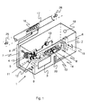
- FIG. 1 a device 1 for cooling room air is shown in a sealed space, which consists of an airtight sealed container 2 with a supply air opening 3 and an exhaust port 4.
- the exhaust port 4 is provided with a grid 5 and connected via a hose, not shown, with the outside air.
- an open-topped vessel 6 is provided with water filled therein, in which the end of a serving as a flow pipe 7 and the end of serving as a return pipe 8 protrude.
- the pipes 7 and 8 form a water circuit 9.
- the pipe 7 is connected to a water pump 10 and leads via a water cooler 11 with a fan 12 to an additional water cooling element 13, preferably with cooling fins made of aluminum, which also has a fan 14.
- the serving as a flow pipe 7 is then out of the container 2 out to a spiral tube 16, which is arranged in a ventilation duct 17. From this helical pipe 16 serving as a return pipe 8 leads back into the container 2 directly to the open vessel 6.
- a control opening 18 is provided, which is closed with a lid or with a glass cover to the water level Check in the open vessel 6 and refill the vessel 6 if necessary.
- an electrical switch 19 is further provided with a fuse and a socket for a - not shown - electrical power supply for the two fans 12 and 14.
- the container 2 is further provided with a heat insulating plate 20, for example Flumroc 3 Alu from Flumroc AG, CH-8890 Flums, lined to minimize heat loss to the outside.
- the pipes 7, 8 and the spiral pipe 16 are formed of copper with a wall thickness of about 1 mm.
- the spiral tube 16 may also be formed as a corrugated pipe made of stainless steel with a very thin wall thickness of about 0.1 mm, whereby a better heat transfer between the cooling water and the warm air to be cooled is ensured.
- the radiator Black ICE GT Stealth 240 Black Ice, Manilla, Philippines has proven particularly useful. This has a plurality of parallel slats, so that a particularly effective and rapid cooling of the cooling water can take place.
- a high-performance fan with an air flow rate of at least 100 m 3 / h preferably used with a particularly high air flow rate of up to 450 m 3 / h.
- Excellent is the fan or fan Jou Jye Turbo PWM with an air speed of 6000 rpm.
- the circulation pump CM10 / 30 Johnson Pump, Sweden is particularly suitable.
- the warm air 25 is now cooled by the cooling water to a lower temperature, which via the pipe 7 as a flow through the spiral tube 16 flows, and there by the temperature difference heat of the warm air 25 deprives.
- the heated water then flows through the pipe 8 as reflux into the open vessel 6.
- the heated water is easily cooled by a slight evaporation of water in the open vessel 6 and then passed through the pump 10 via the pipe 7 to the water cooler 11.
- the water cooler 11 and the additional water cooling element 13 the heated water is cooled by the sucked cooled room air 26 further to a lower temperature.
- the warmer exhaust air 27 which has a slightly higher humidity than the warm outside air 25, discharged via the exhaust duct 21 to the outside. Since the container 2 is very well thermally insulated, heat is prevented from being delivered to the cooled space 30.
- the cooled air 26 sucked in by the cooling device 1 will absorb the excess heat of the cooling water, this heat being led out through the exhaust air 27.
- FIG. 3 the cooling device 1 is placed in a basement 31 of a residential or commercial building near the ventilation duct 17. Since now cooler air 28 is sucked from the basement of the cooling device and out as warm air 29 to the outside, the cooling effect is even better than in the list according to the FIG. 2 ,
- the cooling device 1 is very compact, small, quiet and versatile.
- the water pump 10 and the fans 12 and 14 may be connected to solar cells for the electric drive.
- the cooling device 1 also consumes little power and operates at a low voltage of 12V. It is also very environmentally friendly, since only distilled water without coolant or other additives for the water cycle 9 is used.
- the cooling device 1 is particularly suitable for hot summer days. On less hot days, air cooling quickly reaches its limits.
- the cooling device 1 has proven particularly useful in living rooms, but can also be used in office space or in any other enclosed space such as a tent or caravan.
Landscapes
- Engineering & Computer Science (AREA)
- Chemical & Material Sciences (AREA)
- Combustion & Propulsion (AREA)
- Mechanical Engineering (AREA)
- General Engineering & Computer Science (AREA)
- Life Sciences & Earth Sciences (AREA)
- Sustainable Development (AREA)
Description
- Die Erfindung betrifft eine Vorrichtung zur Kühlung von Raumluft in einem geschlossenen Raum nach dem Oberbegriff des Patentanspruchs 1.
- Wohn- und Büroräume werden an heissen Sommertagen in der Regel mit einer üblichen Klimaanlage gekühlt. Solche Anlagen brauchen viel elektrische Energie und müssen mit erheblichem Aufwand installiert werden (siehe z.B. Patentdokument
DE-913954-C ). Ferner sind solche Klimaanlagen im Betrieb relativ lärmig. - Der vorliegenden Erfindung liegt nun die Aufgabe zugrunde, eine Kühlvorrichtung zu gestalten, die weniger elektrische Energie verbraucht und einfach zu installieren ist.
- Diese Aufgabe wird durch eine Kühlvorrichtung mit den Merkmalen des Patentanspruchs 1 gelöst.
- Die erfindungsgemässe Kühlvorrichtung hat den grossen Vorteil, dass sie sehr kompakt, klein und leise ist. Ferner ist die Kühlvorrichtung vielseitig einsetzbar.
- Weitere Vorteile der Erfindung ergeben sich aus den abhängigen Patentansprüchen und aus der nachfolgenden Beschreibung, in welcher die Erfindung anhand eines in den schematischen Zeichnungen dargestellten Ausführungsbeispieles näher erläutert wird. Es zeigt:
- Fig. 1
- eine schematische Darstellung einer Kühlvorrichtung,
- Fig. 2
- eine Aufstellung der Kühlvorrichtung in einem geschlossenen Raum, und
- Fig. 3
- eine Aufstellung der Kühlvorrichtung ausserhalb eines geschlossenen Raumes.
- In
Figur 1 ist eine Vorrichtung 1 zur Kühlung von Raumluft in einem gesschlossen Raum gezeigt, die aus einem luftdicht abgeschlossenen Behälter 2 mit einer Zuluftöffnung 3 und einer Abluftöffnung 4 besteht. Die Abluftöffnung 4 ist mit einem Gitter 5 versehen und über einen nicht dargestellten Schlauch mit der Aussenluft verbunden. Im Behälter 2 ist ein oben offenes Gefäss 6 mit darin eingefülltem Wasser vorgesehen, in welchem das Ende eine als Vorlauf dienende Rohrleitung 7 und das Ende eines als Rücklauf dienende Rohrleitung 8 hineinragen. Die Rohrleitungen 7 und 8 bilden einen Wasserkreislauf 9. Die Rohrleitung 7 ist an einer Wasserpumpe 10 angeschlossen und führt über einen Wasserkühler 11 mit einem Ventilator 12 zu einem zusätzlichen Wasserkühlelement 13, vorzugsweise mit Kühlrippen aus Aluminium, welches ebenfalls einen Ventilator 14 aufweist. Die als Vorlauf dienende Rohrleitung 7 ist sodann aus dem Behälter 2 hinaus zu einem spiralförmigen Rohr 16 geführt, welches in einem Lüftungskanal 17 angeordnet ist. Von diesem spiralförmigen Rohr 16 führt die als Rücklauf dienende Rohrleitung 8 wieder in den Behälter 2 direkt zu dem offenen Gefäss 6. In der Deckplatte des Behälters 2 ist eine Kontrollöffnung 18 vorgesehen, welche mit einem Deckel oder mit einer Glasabdeckung verschlossen ist, um den Wasserstand in dem offenen Gefäss 6 überprüfen und das Gefäss 6 gegebenenfalls nachfüllen zu können. In der Wand des Behälters 2 ist ferner ein elektrischer Schalter 19 mit einer Sicherung und einer Anschlussbuchse für einer - nicht-dargestellten - elektrischen Stromversorgung für die beiden Ventilatoren 12 und 14 vorgesehen. Der Behälter 2 ist ferner mit einer Wärmedämmplatte 20, beispielsweise Flumroc 3 Alu der Firma Flumroc AG, CH-8890 Flums, ausgekleidet, um den Wärmeverlust nach aussen möglichst gering zu halten. - Die Rohrleitungen 7, 8 und das spiralförmige Rohr 16 sind aus Kupfer mit einer Wandstärke von etwa 1 mm ausgebildet. Alternativ kann das spiralförmige Rohr 16 auch als Wellrohr aus Edelstahl mit einer sehr dünnen Wandstärke von etwa 0.1 mm ausgebildet sein, wodurch eine bessere Wärmeübertragung zwischen dem Kühlwasser und der zu kühlenden warmen Luft gewährleistet ist.
- Als Wasserkühler 4 hat sich der Radiator Black ICE GT Stealth 240 der Firma Black Ice, Manilla, Philippinen, besonders bewährt. Dieser weist eine Vielzahl paralleler Lamellen auf, damit eine besonders wirksame und schnelle Kühlung des Kühlwassers erfolgen kann. Dazu wird ein Hochleistungsventilator mit einem Luftdurchsatz von mindestens 100 m3/h, vorzugsweise mit einem besonders hohen Luftdurchsatz von bis 450 m3/h eingesetzt. Ausgezeichnet geeignet ist der Ventilator oder Lüfter Jou Jye Turbo PWM mit einer Luftdrehzahl von 6000 U/min.
- Als Wasserpumpe 10 ist die Umwälzpumpe CM10/30 der Firma Johnson Pump, Schweden besonders geeignet.
- Anhand der
Figur 2 kann nun die Funktionsweise der Kühlvorrichtung 1 wie folgt erklärt werden: - Der Lüftungskanal 17 mündet in einen zu kühlenden Raum 30, welcher ferner einen Abluftkanal 21 aufweist, um die Raumluft 26 als wärmere Abluft 27 wieder abzuführen, damit kein Überdruck im zu kühlenden Raum 30 entsteht. In
Figur 2 ist die Kühlvorrichtung 1 im Raum 30 aufgestellt, und weist ein an der Abluftöffnung 4 angeschlossenes Abluftrohr 22 auf, welches am Abluftkanal 21 angeschlossenen ist. - Die warme Luft 25 wird nun durch das Kühlwasser auf eine tiefere Temperatur gekühlt, welches über die Rohrleitung 7 als Vorlauf durch das spiralförmige Rohr 16 fliesst, und dort durch die Temperaturdifferenz Wärme der warmen Luft 25 entzieht. Das aufgewärmte Wasser fliesst dann durch die Rohrleitung 8 als Rücklauf in das offene Gefäss 6. Das erwärmte Wasser wird einerseits durch eine geringe Verdunstung des Wassers im offenen Gefäss 6 leicht abgekühlt und dann durch die Pumpe 10 über die Rohrleitung 7 zum Wasserkühler 11 geführt. Durch den Wasserkühler 11 und das zusätzliche Wasserkühlelement 13 wird das erwärmte Wasser durch die angesaugte gekühlte Raumluft 26 weiter auf eine tiefere Temperatur gekühlt. Durch das Abluftrohr 22 wird die wärmere Abluft 27, welche eine etwas höhere Luftfeuchte aufweist als die warme Aussenluft 25, über den Abluftkanal 21 nach aussen abgeführt. Da die Behälter 2 sehr gut wärmegedämmt ist, wird verhindert, dass Wärme an den gekühlten Raum 30 abgegeben wird. Die von der Kühlvorrichtung 1 angesaugte gekühlte Luft 26 wird die überschüssige Wärme des Kühlwassers aufnehmen, wobei diese Wärme durch die Abluft 27 nach aussen geführt wird.
- In
Figur 3 ist die Kühlvorrichtung 1 in einem Keller 31 eines Wohn- oder Geschäftshaus in der Nähe des Lüftungskanals 17 aufgestellt. Da hier nun kühlere Luft 28 aus dem Keller von der Kühlvorrichtung angesaugt und als warme Abluft 29 nach aussen geführt wird, ist der Kühleffekt noch besser als in der Aufstellung gemäss derFigur 2 . - Die Kühlvorrichtung 1 ist sehr kompakt, klein, leise und vielseitig einsetzbar. Die Wasserpumpe 10 und die Ventilatoren 12 und 14 können für den elektrischen Antrieb an Solarzellen angeschlossen sein. Die Kühlvorrichtung 1 verbraucht ferner wenig Strom und wird bei einer niedrigen Spannung von 12 V betrieben. Sie ist zudem sehr umweltfreundlich, da ausschliesslich destilliertes Wasser ohne Kühlmittel oder sonstige Zusätze für den Wasserkreislauf 9 verwendet wird. Die Kühlvorrichtung 1 eignet sich besonders für heisse Sommertage. An weniger warmen Tagen stösst die Luftkühlung schnell an ihre Grenzen.
- Die Kühlvorrichtung 1 hat sich insbesondere bewährt in Wohnräumen, kann aber auch in Büroräumlichkeiten oder in jedem anderen abgeschlossenen Raum wie einem Zelt oder Wohnwagen eingesetzt werden.
Claims (10)
- Vorrichtung (1) zur Kühlung von Raumluft in einem geschlossenen Raum mit einem in den Raum führenden Lüftungsrohr (17), dadurch gekennzeichnet, dass ein geschlossener Behälter (2) mit einem Wasserkreislauf (9) aus einer als Vorlauf dienenden Rohrleitung (7) und einer als Rücklauf dienenden Rohrleitung (8) vorgesehen ist, wobei der Behälter (2) ein offenes Gefäss (6) und eine am Wasserkreislauf (9) angeschlossene Wasserpumpe (10), einen Wasserkühler (11) mit Ventilator (12) und eine Zuluftöffnung (3) und eine Abluftöffnung (4) aufweist, wobei die Rohrleitungen (7, 8) in das offene Gefäss (6) münden, und ein spiralförmiges Rohr (16) im Lüftungsrohr (17) vorgesehen ist, welches am Wasserkreislauf (9) angeschlossen ist.
- Vorrichtung (1) nach Anspruch 1, dadurch gekennzeichnet, dass der Wasserkühler (11) eine Vielzahl paralleler Lamellen aufweist und der Ventilator (12) auf die Lamellen ausgerichtet ist.
- Vorrichtung (1) nach Anspruch 1 oder 2, dadurch gekennzeichnet, dass der Ventilator (12) ein Hochleistungsventilator mit einem Luftdurchsatz von mindestens 100 m3/h ist.
- Vorrichtung (1) nach einem der Ansprüche 1 bis 3, dadurch gekennzeichnet, dass ein zusätzliches Wasserkühlelement (13) mit Ventilator (14) im Wasserkreislauf (9) vorgesehen ist.
- Vorrichtung (1) nach Anspruch 4, dadurch gekennzeichnet, dass das Wasserkühlelement (13) mit Kühlrippen aus Aluminium ausgebildet ist.
- Vorrichtung (1) nach einem der Ansprüche 1 bis 5, dadurch gekennzeichnet, dass der Behälter (2) an der Innenseite mit einer Wärmedämmplatte verkleidet ist.
- Vorrichtung nach einem der Ansprüche 1 bis 6, dadurch gekennzeichnet, dass die Rohrleitungen (7, 8) aus Kupfer bestehen.
- Vorrichtung nach Anspruch 7, dadurch gekennzeichnet, dass das spiralförmige Rohr (16) aus Kupfer besteht oder als Wellrohr aus Edelstahl ausgebildet ist.
- Vorrichtung (1) nach einem der Ansprüche 1 bis 8, dadurch gekennzeichnet, dass destilliertes Wasser im Wasserkreislauf (9) vorgesehen ist.
- Vorrichtung (1) nach einem der Ansprüche 1 bis 9, dadurch gekennzeichnet, dass die Wasserpumpe (10) und die Ventilatoren (12, 14) für den elektrischen Antrieb an Solarzellen angeschlossen sind.
Applications Claiming Priority (1)
| Application Number | Priority Date | Filing Date | Title |
|---|---|---|---|
| CH16402011 | 2011-10-06 |
Publications (2)
| Publication Number | Publication Date |
|---|---|
| EP2578954A1 EP2578954A1 (de) | 2013-04-10 |
| EP2578954B1 true EP2578954B1 (de) | 2015-04-15 |
Family
ID=46980821
Family Applications (1)
| Application Number | Title | Priority Date | Filing Date |
|---|---|---|---|
| EP12186510.9A Active EP2578954B1 (de) | 2011-10-06 | 2012-09-28 | Vorrichtung zur Kühlung von Raumluft |
Country Status (3)
| Country | Link |
|---|---|
| EP (1) | EP2578954B1 (de) |
| ES (1) | ES2538228T3 (de) |
| PT (1) | PT2578954E (de) |
Family Cites Families (4)
| Publication number | Priority date | Publication date | Assignee | Title |
|---|---|---|---|---|
| DE913954C (de) * | 1951-07-20 | 1954-06-24 | Otto Heinz Brandi Dipl Ing | Verfahren zum Betrieb von mit Lueftern ausgeruesteten Luftbehandlungsgeraeten fuer Einzelraeume oder beschraenkte Raumgruppen |
| GB9013225D0 (en) * | 1990-06-13 | 1990-08-01 | Solmate Inc | Integrated heating,cooling and ventilation system |
| JP2005201574A (ja) * | 2004-01-16 | 2005-07-28 | Mitsubishi Electric Building Techno Service Co Ltd | 冷却機と室内機の組合せ、室内機及び冷却機 |
| CN101586851A (zh) * | 2008-05-20 | 2009-11-25 | 煜丰科技股份有限公司 | 移动式空调机 |
-
2012
- 2012-09-28 PT PT121865109T patent/PT2578954E/pt unknown
- 2012-09-28 EP EP12186510.9A patent/EP2578954B1/de active Active
- 2012-09-28 ES ES12186510.9T patent/ES2538228T3/es active Active
Also Published As
| Publication number | Publication date |
|---|---|
| EP2578954A1 (de) | 2013-04-10 |
| ES2538228T3 (es) | 2015-06-18 |
| PT2578954E (pt) | 2015-08-17 |
Similar Documents
| Publication | Publication Date | Title |
|---|---|---|
| DE102015107820A1 (de) | Heizpumpe | |
| EP2193700B1 (de) | Schaltschrank für eine windkraftanlage | |
| DE2739373A1 (de) | Waermegewinnungseinrichtung | |
| DE202019100059U1 (de) | Inverteranordnung | |
| EP1207732A2 (de) | Schaltschrank mit einer Klimatisierungseinrichtung | |
| EP2524172B1 (de) | Wärmeübertrageranordnung | |
| DE4114915A1 (de) | Verfahren und vorrichtung zur energie-einsparung bei gefriergeraeten bzw.: kaeltegeraet mit vorrichtung zur kuehlluftzufuhr | |
| AT402559B (de) | Einrichtung zur erwärmung bzw. kühlung von gebäuden | |
| DE602004004536T2 (de) | Kondensatpumpe für eine dachklimaanlage | |
| EP2218971A2 (de) | Temperierungssystem | |
| DE112014000525T5 (de) | Heizsystem | |
| DE202008005825U1 (de) | Gebläsekonvektorsystem | |
| WO2013037348A2 (de) | Verfahren zum kontinuierlichen gewinnen von strom, gebäude mit exergie, verfahren zum reduzieren einer stoffbelastung, verfahren zum führen von luft in einem wohngebäude, verfahren zum betreiben einer wärmepumpen anordnung, wärmetauscher und verfahren zum kühlen eines gebäudes, verfahren zum erwärmen von brauchwasser | |
| EP2578954A1 (de) | Vorrichtung zur Kühlung von Raumluft | |
| DE10022354C1 (de) | Rekuperativer Vertikalflurraumlüfter | |
| EP2965020B1 (de) | Anlage zum konditionieren der luft in einem gebäude | |
| DE29711263U1 (de) | Vorrichtung zur Gewinnung solarer Energie | |
| EP4431832A1 (de) | System und verfahren zur gezielten gleichzeitigen nutzung von sonnenstrahlung zur stromerzeugung und heizen eines flüssigkeitskreislaufs | |
| DE29908205U1 (de) | Vorrichtung zur Umwandlung von Solarenergie in elektrische Energie und Einrichtung an einem Gebäude mit einer derartigen Vorrichtung | |
| EP4437280B1 (de) | System zur klimatisierung eines gebäudes | |
| DE202015002031U1 (de) | Dauerbelüftungsvorrichtung zur Belüftung von Innenwand/Schrank Zwischenräumen, zur Verhinderung von Feuchteschäden wie Schimmelbefall, Fäulnisbakterien, muffiger Geruch und den dadurch hervorgerufenen Erkrankungen | |
| AT413756B (de) | Raumklimaeinrichtung | |
| CA2750261C (en) | Heating apparatus using solar energy and method of heating using solar energy | |
| DE202017102827U1 (de) | Energiesparendes Temperaturregelungssystem im Maschinenraum | |
| DE2723503A1 (de) | Klimaanlage fuer ein hochisoliertes gebaeude mit einer belueftungseinrichtung |
Legal Events
| Date | Code | Title | Description |
|---|---|---|---|
| PUAI | Public reference made under article 153(3) epc to a published international application that has entered the european phase |
Free format text: ORIGINAL CODE: 0009012 |
|
| AK | Designated contracting states |
Kind code of ref document: A1 Designated state(s): AL AT BE BG CH CY CZ DE DK EE ES FI FR GB GR HR HU IE IS IT LI LT LU LV MC MK MT NL NO PL PT RO RS SE SI SK SM TR |
|
| AX | Request for extension of the european patent |
Extension state: BA ME |
|
| 17P | Request for examination filed |
Effective date: 20130930 |
|
| RBV | Designated contracting states (corrected) |
Designated state(s): AL AT BE BG CH CY CZ DE DK EE ES FI FR GB GR HR HU IE IS IT LI LT LU LV MC MK MT NL NO PL PT RO RS SE SI SK SM TR |
|
| GRAP | Despatch of communication of intention to grant a patent |
Free format text: ORIGINAL CODE: EPIDOSNIGR1 |
|
| RIC1 | Information provided on ipc code assigned before grant |
Ipc: F24F 3/06 20060101AFI20141015BHEP Ipc: F24F 5/00 20060101ALI20141015BHEP Ipc: F24F 12/00 20060101ALI20141015BHEP |
|
| INTG | Intention to grant announced |
Effective date: 20141106 |
|
| GRAS | Grant fee paid |
Free format text: ORIGINAL CODE: EPIDOSNIGR3 |
|
| GRAA | (expected) grant |
Free format text: ORIGINAL CODE: 0009210 |
|
| AK | Designated contracting states |
Kind code of ref document: B1 Designated state(s): AL AT BE BG CH CY CZ DE DK EE ES FI FR GB GR HR HU IE IS IT LI LT LU LV MC MK MT NL NO PL PT RO RS SE SI SK SM TR |
|
| REG | Reference to a national code |
Ref country code: GB Ref legal event code: FG4D Free format text: NOT ENGLISH Ref country code: CH Ref legal event code: EP |
|
| REG | Reference to a national code |
Ref country code: IE Ref legal event code: FG4D Free format text: LANGUAGE OF EP DOCUMENT: GERMAN |
|
| REG | Reference to a national code |
Ref country code: AT Ref legal event code: REF Ref document number: 722216 Country of ref document: AT Kind code of ref document: T Effective date: 20150515 |
|
| REG | Reference to a national code |
Ref country code: DE Ref legal event code: R096 Ref document number: 502012002847 Country of ref document: DE Effective date: 20150603 |
|
| REG | Reference to a national code |
Ref country code: ES Ref legal event code: FG2A Ref document number: 2538228 Country of ref document: ES Kind code of ref document: T3 Effective date: 20150618 |
|
| REG | Reference to a national code |
Ref country code: CH Ref legal event code: NV Representative=s name: SPIERENBURG AND PARTNER AG, PATENT- UND MARKEN, CH |
|
| REG | Reference to a national code |
Ref country code: PT Ref legal event code: SC4A Free format text: AVAILABILITY OF NATIONAL TRANSLATION Effective date: 20150710 |
|
| REG | Reference to a national code |
Ref country code: NL Ref legal event code: VDEP Effective date: 20150415 |
|
| REG | Reference to a national code |
Ref country code: LT Ref legal event code: MG4D |
|
| PG25 | Lapsed in a contracting state [announced via postgrant information from national office to epo] |
Ref country code: NL Free format text: LAPSE BECAUSE OF FAILURE TO SUBMIT A TRANSLATION OF THE DESCRIPTION OR TO PAY THE FEE WITHIN THE PRESCRIBED TIME-LIMIT Effective date: 20150415 |
|
| PG25 | Lapsed in a contracting state [announced via postgrant information from national office to epo] |
Ref country code: NO Free format text: LAPSE BECAUSE OF FAILURE TO SUBMIT A TRANSLATION OF THE DESCRIPTION OR TO PAY THE FEE WITHIN THE PRESCRIBED TIME-LIMIT Effective date: 20150715 Ref country code: FI Free format text: LAPSE BECAUSE OF FAILURE TO SUBMIT A TRANSLATION OF THE DESCRIPTION OR TO PAY THE FEE WITHIN THE PRESCRIBED TIME-LIMIT Effective date: 20150415 Ref country code: HR Free format text: LAPSE BECAUSE OF FAILURE TO SUBMIT A TRANSLATION OF THE DESCRIPTION OR TO PAY THE FEE WITHIN THE PRESCRIBED TIME-LIMIT Effective date: 20150415 Ref country code: LT Free format text: LAPSE BECAUSE OF FAILURE TO SUBMIT A TRANSLATION OF THE DESCRIPTION OR TO PAY THE FEE WITHIN THE PRESCRIBED TIME-LIMIT Effective date: 20150415 |
|
| PG25 | Lapsed in a contracting state [announced via postgrant information from national office to epo] |
Ref country code: GR Free format text: LAPSE BECAUSE OF FAILURE TO SUBMIT A TRANSLATION OF THE DESCRIPTION OR TO PAY THE FEE WITHIN THE PRESCRIBED TIME-LIMIT Effective date: 20150716 Ref country code: LV Free format text: LAPSE BECAUSE OF FAILURE TO SUBMIT A TRANSLATION OF THE DESCRIPTION OR TO PAY THE FEE WITHIN THE PRESCRIBED TIME-LIMIT Effective date: 20150415 Ref country code: IS Free format text: LAPSE BECAUSE OF FAILURE TO SUBMIT A TRANSLATION OF THE DESCRIPTION OR TO PAY THE FEE WITHIN THE PRESCRIBED TIME-LIMIT Effective date: 20150815 Ref country code: RS Free format text: LAPSE BECAUSE OF FAILURE TO SUBMIT A TRANSLATION OF THE DESCRIPTION OR TO PAY THE FEE WITHIN THE PRESCRIBED TIME-LIMIT Effective date: 20150415 |
|
| REG | Reference to a national code |
Ref country code: DE Ref legal event code: R097 Ref document number: 502012002847 Country of ref document: DE |
|
| PG25 | Lapsed in a contracting state [announced via postgrant information from national office to epo] |
Ref country code: DK Free format text: LAPSE BECAUSE OF FAILURE TO SUBMIT A TRANSLATION OF THE DESCRIPTION OR TO PAY THE FEE WITHIN THE PRESCRIBED TIME-LIMIT Effective date: 20150415 Ref country code: EE Free format text: LAPSE BECAUSE OF FAILURE TO SUBMIT A TRANSLATION OF THE DESCRIPTION OR TO PAY THE FEE WITHIN THE PRESCRIBED TIME-LIMIT Effective date: 20150415 |
|
| PLBE | No opposition filed within time limit |
Free format text: ORIGINAL CODE: 0009261 |
|
| STAA | Information on the status of an ep patent application or granted ep patent |
Free format text: STATUS: NO OPPOSITION FILED WITHIN TIME LIMIT |
|
| PG25 | Lapsed in a contracting state [announced via postgrant information from national office to epo] |
Ref country code: RO Free format text: LAPSE BECAUSE OF NON-PAYMENT OF DUE FEES Effective date: 20150415 Ref country code: PL Free format text: LAPSE BECAUSE OF FAILURE TO SUBMIT A TRANSLATION OF THE DESCRIPTION OR TO PAY THE FEE WITHIN THE PRESCRIBED TIME-LIMIT Effective date: 20150415 Ref country code: CZ Free format text: LAPSE BECAUSE OF FAILURE TO SUBMIT A TRANSLATION OF THE DESCRIPTION OR TO PAY THE FEE WITHIN THE PRESCRIBED TIME-LIMIT Effective date: 20150415 Ref country code: SK Free format text: LAPSE BECAUSE OF FAILURE TO SUBMIT A TRANSLATION OF THE DESCRIPTION OR TO PAY THE FEE WITHIN THE PRESCRIBED TIME-LIMIT Effective date: 20150415 |
|
| 26N | No opposition filed |
Effective date: 20160118 |
|
| PG25 | Lapsed in a contracting state [announced via postgrant information from national office to epo] |
Ref country code: MC Free format text: LAPSE BECAUSE OF FAILURE TO SUBMIT A TRANSLATION OF THE DESCRIPTION OR TO PAY THE FEE WITHIN THE PRESCRIBED TIME-LIMIT Effective date: 20150415 Ref country code: LU Free format text: LAPSE BECAUSE OF FAILURE TO SUBMIT A TRANSLATION OF THE DESCRIPTION OR TO PAY THE FEE WITHIN THE PRESCRIBED TIME-LIMIT Effective date: 20150928 |
|
| PG25 | Lapsed in a contracting state [announced via postgrant information from national office to epo] |
Ref country code: SI Free format text: LAPSE BECAUSE OF FAILURE TO SUBMIT A TRANSLATION OF THE DESCRIPTION OR TO PAY THE FEE WITHIN THE PRESCRIBED TIME-LIMIT Effective date: 20150415 |
|
| REG | Reference to a national code |
Ref country code: IE Ref legal event code: MM4A |
|
| PG25 | Lapsed in a contracting state [announced via postgrant information from national office to epo] |
Ref country code: IE Free format text: LAPSE BECAUSE OF NON-PAYMENT OF DUE FEES Effective date: 20150928 |
|
| REG | Reference to a national code |
Ref country code: FR Ref legal event code: PLFP Year of fee payment: 5 |
|
| PG25 | Lapsed in a contracting state [announced via postgrant information from national office to epo] |
Ref country code: MT Free format text: LAPSE BECAUSE OF FAILURE TO SUBMIT A TRANSLATION OF THE DESCRIPTION OR TO PAY THE FEE WITHIN THE PRESCRIBED TIME-LIMIT Effective date: 20150415 |
|
| GBPC | Gb: european patent ceased through non-payment of renewal fee |
Effective date: 20160928 |
|
| PG25 | Lapsed in a contracting state [announced via postgrant information from national office to epo] |
Ref country code: BG Free format text: LAPSE BECAUSE OF FAILURE TO SUBMIT A TRANSLATION OF THE DESCRIPTION OR TO PAY THE FEE WITHIN THE PRESCRIBED TIME-LIMIT Effective date: 20150415 Ref country code: HU Free format text: LAPSE BECAUSE OF FAILURE TO SUBMIT A TRANSLATION OF THE DESCRIPTION OR TO PAY THE FEE WITHIN THE PRESCRIBED TIME-LIMIT; INVALID AB INITIO Effective date: 20120928 Ref country code: SM Free format text: LAPSE BECAUSE OF FAILURE TO SUBMIT A TRANSLATION OF THE DESCRIPTION OR TO PAY THE FEE WITHIN THE PRESCRIBED TIME-LIMIT Effective date: 20150415 |
|
| PG25 | Lapsed in a contracting state [announced via postgrant information from national office to epo] |
Ref country code: CY Free format text: LAPSE BECAUSE OF FAILURE TO SUBMIT A TRANSLATION OF THE DESCRIPTION OR TO PAY THE FEE WITHIN THE PRESCRIBED TIME-LIMIT Effective date: 20150415 Ref country code: SE Free format text: LAPSE BECAUSE OF FAILURE TO SUBMIT A TRANSLATION OF THE DESCRIPTION OR TO PAY THE FEE WITHIN THE PRESCRIBED TIME-LIMIT Effective date: 20150415 |
|
| PG25 | Lapsed in a contracting state [announced via postgrant information from national office to epo] |
Ref country code: BE Free format text: LAPSE BECAUSE OF NON-PAYMENT OF DUE FEES Effective date: 20150930 Ref country code: GB Free format text: LAPSE BECAUSE OF NON-PAYMENT OF DUE FEES Effective date: 20160928 |
|
| PG25 | Lapsed in a contracting state [announced via postgrant information from national office to epo] |
Ref country code: TR Free format text: LAPSE BECAUSE OF FAILURE TO SUBMIT A TRANSLATION OF THE DESCRIPTION OR TO PAY THE FEE WITHIN THE PRESCRIBED TIME-LIMIT Effective date: 20150415 |
|
| REG | Reference to a national code |
Ref country code: FR Ref legal event code: PLFP Year of fee payment: 6 |
|
| PG25 | Lapsed in a contracting state [announced via postgrant information from national office to epo] |
Ref country code: MK Free format text: LAPSE BECAUSE OF FAILURE TO SUBMIT A TRANSLATION OF THE DESCRIPTION OR TO PAY THE FEE WITHIN THE PRESCRIBED TIME-LIMIT Effective date: 20150415 |
|
| REG | Reference to a national code |
Ref country code: FR Ref legal event code: PLFP Year of fee payment: 7 |
|
| PG25 | Lapsed in a contracting state [announced via postgrant information from national office to epo] |
Ref country code: AL Free format text: LAPSE BECAUSE OF FAILURE TO SUBMIT A TRANSLATION OF THE DESCRIPTION OR TO PAY THE FEE WITHIN THE PRESCRIBED TIME-LIMIT Effective date: 20150415 |
|
| REG | Reference to a national code |
Ref country code: CH Ref legal event code: U11 Free format text: ST27 STATUS EVENT CODE: U-0-0-U10-U11 (AS PROVIDED BY THE NATIONAL OFFICE) Effective date: 20251001 |
|
| PGFP | Annual fee paid to national office [announced via postgrant information from national office to epo] |
Ref country code: PT Payment date: 20250912 Year of fee payment: 14 |
|
| PGFP | Annual fee paid to national office [announced via postgrant information from national office to epo] |
Ref country code: DE Payment date: 20250919 Year of fee payment: 14 |
|
| PGFP | Annual fee paid to national office [announced via postgrant information from national office to epo] |
Ref country code: FR Payment date: 20250924 Year of fee payment: 14 Ref country code: AT Payment date: 20250918 Year of fee payment: 14 |
|
| PGFP | Annual fee paid to national office [announced via postgrant information from national office to epo] |
Ref country code: IT Payment date: 20250930 Year of fee payment: 14 |
|
| PGFP | Annual fee paid to national office [announced via postgrant information from national office to epo] |
Ref country code: CH Payment date: 20251001 Year of fee payment: 14 |
|
| PGFP | Annual fee paid to national office [announced via postgrant information from national office to epo] |
Ref country code: ES Payment date: 20251020 Year of fee payment: 14 |