EP2578750A2 - System for anchoring in the ground the end of a highway guardrail - Google Patents
System for anchoring in the ground the end of a highway guardrail Download PDFInfo
- Publication number
- EP2578750A2 EP2578750A2 EP12164562.6A EP12164562A EP2578750A2 EP 2578750 A2 EP2578750 A2 EP 2578750A2 EP 12164562 A EP12164562 A EP 12164562A EP 2578750 A2 EP2578750 A2 EP 2578750A2
- Authority
- EP
- European Patent Office
- Prior art keywords
- anchoring
- guardrail
- ground
- tubes
- tube
- Prior art date
- Legal status (The legal status is an assumption and is not a legal conclusion. Google has not performed a legal analysis and makes no representation as to the accuracy of the status listed.)
- Granted
Links
Images

Classifications
-
- E—FIXED CONSTRUCTIONS
- E01—CONSTRUCTION OF ROADS, RAILWAYS, OR BRIDGES
- E01F—ADDITIONAL WORK, SUCH AS EQUIPPING ROADS OR THE CONSTRUCTION OF PLATFORMS, HELICOPTER LANDING STAGES, SIGNS, SNOW FENCES, OR THE LIKE
- E01F15/00—Safety arrangements for slowing, redirecting or stopping errant vehicles, e.g. guard posts or bollards; Arrangements for reducing damage to roadside structures due to vehicular impact
- E01F15/14—Safety arrangements for slowing, redirecting or stopping errant vehicles, e.g. guard posts or bollards; Arrangements for reducing damage to roadside structures due to vehicular impact specially adapted for local protection, e.g. for bridge piers, for traffic islands
- E01F15/143—Protecting devices located at the ends of barriers
-
- E—FIXED CONSTRUCTIONS
- E01—CONSTRUCTION OF ROADS, RAILWAYS, OR BRIDGES
- E01F—ADDITIONAL WORK, SUCH AS EQUIPPING ROADS OR THE CONSTRUCTION OF PLATFORMS, HELICOPTER LANDING STAGES, SIGNS, SNOW FENCES, OR THE LIKE
- E01F15/00—Safety arrangements for slowing, redirecting or stopping errant vehicles, e.g. guard posts or bollards; Arrangements for reducing damage to roadside structures due to vehicular impact
- E01F15/02—Continuous barriers extending along roads or between traffic lanes
- E01F15/04—Continuous barriers extending along roads or between traffic lanes essentially made of longitudinal beams or rigid strips supported above ground at spaced points
-
- E—FIXED CONSTRUCTIONS
- E01—CONSTRUCTION OF ROADS, RAILWAYS, OR BRIDGES
- E01F—ADDITIONAL WORK, SUCH AS EQUIPPING ROADS OR THE CONSTRUCTION OF PLATFORMS, HELICOPTER LANDING STAGES, SIGNS, SNOW FENCES, OR THE LIKE
- E01F15/00—Safety arrangements for slowing, redirecting or stopping errant vehicles, e.g. guard posts or bollards; Arrangements for reducing damage to roadside structures due to vehicular impact
- E01F15/02—Continuous barriers extending along roads or between traffic lanes
- E01F15/04—Continuous barriers extending along roads or between traffic lanes essentially made of longitudinal beams or rigid strips supported above ground at spaced points
- E01F15/0476—Foundations
Definitions
- the object of the current invention is a system for anchoring in the ground the end of a highway guardrail, which system comprises at least one anchoring tube to be installed partly in the ground, by the aid of which the end of the guardrail is anchored in the ground.
- the invention relates generally to highway guardrails and more particularly to the center guardrails of traffic lanes, which have recently become rapidly more widespread. They are used for safety reasons to prevent meeting accidents of vehicles moving in opposite directions. By means of center guardrails, of course, overtaking can be prevented in places where it would be dangerous. Center guardrails have become widely adopted, particularly on highways with an overtaking lane.
- Highway guardrails are composed of essentially vertical metallic guardrail pillars that are at a distance from each other, embedded and/or fixed into the ground, as well as of metallic guides, i.e. essentially horizontal guardrail parts, fixed to them.
- the terms “vertical” and “horizontal” are not, of course, mathematically precise in this context, because they vary according to the profile of the ground surface on the highway.
- Publication EP 2 298 999 A2 presents a solution for anchoring the end of a guardrail by the aid of a separate anchoring unit.
- the anchoring unit is fixed into the ground with anchoring tubes to be hit through the holes in it.
- the top ends of the anchoring tubes comprise widenings, which come against the base plate of the anchoring unit when the anchoring tubes have been hit into their position.
- a drawback with this system is that the anchoring unit and/or the butt end of the guardrail cannot be replaced without pulling the anchoring tubes up out of the ground. If the tubes are pulled up, new tubes cannot be installed into the same holes, but instead some soil improvement work is needed. Otherwise the anchoring tubes will not necessarily adhere to the ground sufficiently strongly.
- this solution also does not enable installation of the anchoring tubes at an angle with respect to the ground surface, at which angle their grip in the ground would improve.
- the anchoring tubes When hitting into an angle in the solution presented in the publication, the anchoring tubes would not have any lateral support at all, in which case it would be awkward to hit an anchoring tube into a certain angle.
- the widenings on the top parts of the anchoring tubes prevent them, in an inclined installation, being installed adjoined to the base plate because the anchoring tube is left to support from the widening of the top part.
- At an angle in this context means that the angle of an anchoring tube is, when installed into its position, of an essentially different direction than 90° with respect to the ground surface.
- the aim of the invention is to achieve a new type of system for anchoring in the ground the end of a highway guardrail.
- the system according to the invention is characterized in that the end of the guardrail comprises at least one anchoring tube and guide part.
- anchoring tube in this context refers, in addition to a tube, also to various profiles, such as e.g. I-profile, which is not included in the geometrical definition of a tube.
- the anchoring tubes are preferably of tube profile.
- One preferred embodiment of the system according to the invention is characterized in that there are two units of anchoring tubes, as is per se known in the art, and they are installed consecutively as viewed in the longitudinal direction of the guardrail.
- Another preferred embodiment of the system according to the invention is characterized in that the end of the guardrail comprises installation holes for the anchoring tubes and also guide parts against the flange part of an anchoring tube.
- Yet another preferred embodiment of the system according to the invention is characterized in that the installation holes and the cross-sections of the anchoring tubes are essentially of the same shape, preferably of equiangular quadrilateral shape, such that the outer dimension of the tube is smaller than the inner dimension of the hole.
- an end of the guardrail can, if necessary (e.g. after an accident), be detached from the anchoring tubes and can be replaced without the anchoring tubes needing to be lifted out of the ground.
- the system comprises at least one anchoring tube to be installed partly in the ground, by the aid of which the end of the guardrail is anchored in the ground.
- the angle of the anchoring tube in this embodiment is of an essentially different magnitude than 90° with respect to the surface of the ground.
- One preferred embodiment of the system described above is characterized in that there are two units of anchoring tubes and they are arranged consecutively at a distance from each other as viewed in the longitudinal direction of the guardrail, and in that of the anchoring tubes one is installed vertically into the ground and the other at an angle with respect to this.
- An advantage of the aforementioned second solution that can be mentioned is that an end of the guardrail can be anchored without separate fixing means. Since the anchoring tubes are of different directions and installed through holes of corresponding directions, the end of the guardrail is not able to detach from the anchoring tubes.
- Figs. 1 and 2 thus present a highway guardrail 1, e.g. a center guardrail, and more particularly the second end of the guardrail.
- the end 2 of the guardrail is detachably anchored in the ground 5 with two anchoring tubes 3, with the end of the guardrail being fixed to the part of the anchoring tubes that is above ground.
- the anchoring tubes are hit, or in some other manner installed, into the ground 5 with a tool intended for this purpose, such as with a tamping machine.
- Holes Fig. 3
- the length of the anchoring tubes 3 can vary, but is e.g. between 1-2 m. When they are installed (hit) into the ground, they are for the most part, but not completely, in the ground.
- the anchoring tubes 3 are arranged consecutively at a distance from each other in the longitudinal direction of the guardrail 1.
- the distance can vary according to need, but can be e.g. between 50-100 cm.
- the quantity of anchoring tubes 3 can vary. There is at least one of them, but most preferably two. A larger quantity than this is not excluded.
- the anchoring tubes 3 are parallel with each other and diverge to some extent from the vertical direction. As will be explained below, the anchoring tubes 3 can have other attitudes also, according to need.
- Figs. 3 and 4 present a simplified anchoring unit, from which it is seen that the holes 4 made for the anchoring tubes 3 are preferably equiangular quadrilateral in shape.
- the anchoring tubes 3 are, of course, essentially the same in their cross-sectional shape as the holes 4, but slightly smaller in their outer dimensions than the inner dimensions of the holes so that the anchoring tubes 3 fit through the holes 4.
- the shape of the holes and of the anchoring tubes can be other than equiangular quadrilateral, e.g. round, triangular or polygonal.
- a shape differing from a round shape, such as an angular shape, has the advantage that the holes in the guide part 6 of a hole and in the anchoring tube 3 for the bolted joint can be easily aligned, because the tube is not able to rotate in the hole.
- the alignment of the holes in the vertical direction occurs e.g. such that when the impact tool of the tamping machine meets guardrail or the fixing unit or the top surface of the guardrail, from where it is no longer able to hit the anchoring tube deeper, the holes are aligned. This is seen e.g. from Fig. 1 , in which the top surfaces of the anchoring tubes 3 are on the same plane as the top surface of the guardrail.
- the guide part 6 When talking about the guide part 6, this can mean separate platelike parts, such as in Figs. 5 and 6 , or tube-shaped parts, inside which an anchoring tube 3 is placed when installing the anchoring tube 3 in the ground.
- tube-shaped parts As guide parts 6 it is essential that the cross-sections of the anchoring tubes 3 and of the guide parts are of the same shapes such that the outer dimension of the anchoring tube 3 is smaller than the inner dimension of the guide part 6.
- the height of the guide part 6 is preferably over 40 mm and according to the most preferable embodiment over 50 mm.
- the height of a guide part 6 in this context means the distance that an anchoring tube 3 travels inside, or supported by, the guide part 6.
- the bolted joints of the anchoring tubes 3 are presented in more detail in Figs. 5 and 6 .
- Guide parts 6, in which through-holes have been made for the bolts 7, are fixed to the anchoring unit 2, e.g. welded at the point of the edges of the holes.
- the anchoring tubes 3 comprise corresponding holes, in which case the bolts 7 extend through both the guide parts 6 and the anchoring tubes.
- the bolted joint is tightened finally with nuts.
- the anchoring unit 2 is fixed at its second end to the guardrail e.g. with a bolted joint.
- Fig. 7 presents a solution according to one preferred embodiment of the invention.
- the anchoring tubes 3 are at a different angle to each other.
- the first anchoring tube 3 is essentially vertical and the second tube is at an angle, which is e.g. approx. 10-20° with respect to this.
- the holes, through which the tubes are hit into the ground are in the same way at an angle with respect to each other.
- the guide parts 6 of the holes are installed such that in one of the holes they are vertical and in the other hole they are at an angle to this.
- the end 2 of the guardrail is not able to detach from the anchoring tubes 3 even if no separate fixing means were used.
- the end of the guardrail is beveled on its bottom edge such that it settles against the ground evenly.
- Fig. 8 the end of the guardrail is formed from a separate anchoring unit, which is fixed to the guardrail 1.
- the anchoring tubes 3 are installed into the ground 5 through the holes formed in the anchoring unit.
- bolted joints 8 are used in this embodiment. In this case, when viewed from the center part of the guardrail the latter anchoring tube is shorter than the first anchoring tube.
Landscapes
- Engineering & Computer Science (AREA)
- Architecture (AREA)
- Civil Engineering (AREA)
- Structural Engineering (AREA)
- Refuge Islands, Traffic Blockers, Or Guard Fence (AREA)
- Bridges Or Land Bridges (AREA)
Abstract
Description
- The object of the current invention is a system for anchoring in the ground the end of a highway guardrail, which system comprises at least one anchoring tube to be installed partly in the ground, by the aid of which the end of the guardrail is anchored in the ground.
- The invention relates generally to highway guardrails and more particularly to the center guardrails of traffic lanes, which have recently become rapidly more widespread. They are used for safety reasons to prevent meeting accidents of vehicles moving in opposite directions. By means of center guardrails, of course, overtaking can be prevented in places where it would be dangerous. Center guardrails have become widely adopted, particularly on highways with an overtaking lane.
- Highway guardrails are composed of essentially vertical metallic guardrail pillars that are at a distance from each other, embedded and/or fixed into the ground, as well as of metallic guides, i.e. essentially horizontal guardrail parts, fixed to them. The terms "vertical" and "horizontal" are not, of course, mathematically precise in this context, because they vary according to the profile of the ground surface on the highway.
- It is typical for a highway guardrail that it is, in one way or another, anchored in the ground so that it is able to receive the collision forces of vehicles in accident situations. Earlier it has been usual to anchor a guardrail with only vertical guardrail pillars. A widespread practice nowadays is that the ends of a guardrail are anchored firmly in the ground and the center part of the guardrail yields for absorbing collision forces.
- The anchoring of the ends of a guardrail has earlier been implemented by digging a pit in the ground and by casting an anchoring means for the end of the guardrail in the ground. The end of the guardrail is thus fixed to this anchoring means. This method, however, has the drawback that already finished asphalt must be broken when digging a pit. Correspondingly, the repair of the road after installation incurs costs. The procedure is also time-consuming.
-
Publication EP 2 298 999 A2 presents a solution for anchoring the end of a guardrail by the aid of a separate anchoring unit. The anchoring unit is fixed into the ground with anchoring tubes to be hit through the holes in it. The top ends of the anchoring tubes comprise widenings, which come against the base plate of the anchoring unit when the anchoring tubes have been hit into their position. A drawback with this system is that the anchoring unit and/or the butt end of the guardrail cannot be replaced without pulling the anchoring tubes up out of the ground. If the tubes are pulled up, new tubes cannot be installed into the same holes, but instead some soil improvement work is needed. Otherwise the anchoring tubes will not necessarily adhere to the ground sufficiently strongly. On the other hand, this solution also does not enable installation of the anchoring tubes at an angle with respect to the ground surface, at which angle their grip in the ground would improve. When hitting into an angle in the solution presented in the publication, the anchoring tubes would not have any lateral support at all, in which case it would be awkward to hit an anchoring tube into a certain angle. Also the widenings on the top parts of the anchoring tubes prevent them, in an inclined installation, being installed adjoined to the base plate because the anchoring tube is left to support from the widening of the top part. At an angle in this context means that the angle of an anchoring tube is, when installed into its position, of an essentially different direction than 90° with respect to the ground surface. - The aim of the invention is to achieve a new type of system for anchoring in the ground the end of a highway guardrail. The system according to the invention is characterized in that the end of the guardrail comprises at least one anchoring tube and guide part.
- The term anchoring tube in this context refers, in addition to a tube, also to various profiles, such as e.g. I-profile, which is not included in the geometrical definition of a tube. The anchoring tubes are preferably of tube profile.
- One preferred embodiment of the system according to the invention is characterized in that there are two units of anchoring tubes, as is per se known in the art, and they are installed consecutively as viewed in the longitudinal direction of the guardrail.
- Another preferred embodiment of the system according to the invention is characterized in that the end of the guardrail comprises installation holes for the anchoring tubes and also guide parts against the flange part of an anchoring tube.
- Yet another preferred embodiment of the system according to the invention is characterized in that the installation holes and the cross-sections of the anchoring tubes are essentially of the same shape, preferably of equiangular quadrilateral shape, such that the outer dimension of the tube is smaller than the inner dimension of the hole.
- In a preferred embodiment one of the advantages of the invention that can be mentioned is that an end of the guardrail can, if necessary (e.g. after an accident), be detached from the anchoring tubes and can be replaced without the anchoring tubes needing to be lifted out of the ground.
- According to one preferred embodiment the system comprises at least one anchoring tube to be installed partly in the ground, by the aid of which the end of the guardrail is anchored in the ground. The angle of the anchoring tube in this embodiment is of an essentially different magnitude than 90° with respect to the surface of the ground.
- One preferred embodiment of the system described above is characterized in that there are two units of anchoring tubes and they are arranged consecutively at a distance from each other as viewed in the longitudinal direction of the guardrail, and in that of the anchoring tubes one is installed vertically into the ground and the other at an angle with respect to this.
- An advantage of the aforementioned second solution that can be mentioned is that an end of the guardrail can be anchored without separate fixing means. Since the anchoring tubes are of different directions and installed through holes of corresponding directions, the end of the guardrail is not able to detach from the anchoring tubes.
- It must be noted that when the description and the claims refer to an end of the guardrail, this can explicitly mean an end of the guardrail or it can mean the separate anchoring unit fixed to it. For the sake of clarity, the designation end of the guardrail is used for both.
- By the aid of the invention the forces produced in the guardrail by a possible collision into the guardrail are transmitted to the flank of the anchoring tubes at the end of the guardrail and via it into the ground.
- In the following, the invention will be described in more detail by the aid of some preferred embodiments with reference to the attached drawings, wherein
-
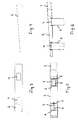
Fig. 1 presents highway guardrail according to the invention, as viewed from the side. -
Fig. 2 presents the same asFig. 1 , but as viewed from above. -
Fig. 3 presents the holes of an anchoring unit, as viewed from below the anchoring unit. -
Fig. 4 presents the same asFig. 3 , but as viewed from the side. -
Fig. 5 presents an anchoring unit and anchoring tubes as viewed from above. -
Fig. 6 presents the same asFig. 5 , but as viewed from above. -
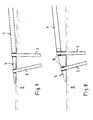
Fig. 7 presents an anchoring method according to one preferred embodiment of the invention for the end of a guardrail. -
Fig. 8 presents an anchoring method according to a second preferred embodiment of the invention for the end of a guardrail. -
Figs. 1 and 2 thus present ahighway guardrail 1, e.g. a center guardrail, and more particularly the second end of the guardrail. Theend 2 of the guardrail is detachably anchored in theground 5 with twoanchoring tubes 3, with the end of the guardrail being fixed to the part of the anchoring tubes that is above ground. The anchoring tubes are hit, or in some other manner installed, into theground 5 with a tool intended for this purpose, such as with a tamping machine. Holes (Fig. 3 ) are made in theend 2 of the guardrail, through which holes the anchoring tubes are hit so as to be for the most part in the ground. The length of theanchoring tubes 3 can vary, but is e.g. between 1-2 m. When they are installed (hit) into the ground, they are for the most part, but not completely, in the ground. - The
anchoring tubes 3 are arranged consecutively at a distance from each other in the longitudinal direction of theguardrail 1. The distance can vary according to need, but can be e.g. between 50-100 cm. Of course, the quantity ofanchoring tubes 3 can vary. There is at least one of them, but most preferably two. A larger quantity than this is not excluded. - In the solution presented by
Fig. 1 theanchoring tubes 3 are parallel with each other and diverge to some extent from the vertical direction. As will be explained below, theanchoring tubes 3 can have other attitudes also, according to need. -
Figs. 3 and 4 present a simplified anchoring unit, from which it is seen that theholes 4 made for theanchoring tubes 3 are preferably equiangular quadrilateral in shape. Theanchoring tubes 3 are, of course, essentially the same in their cross-sectional shape as theholes 4, but slightly smaller in their outer dimensions than the inner dimensions of the holes so that theanchoring tubes 3 fit through theholes 4. The shape of the holes and of the anchoring tubes can be other than equiangular quadrilateral, e.g. round, triangular or polygonal. A shape differing from a round shape, such as an angular shape, has the advantage that the holes in theguide part 6 of a hole and in the anchoringtube 3 for the bolted joint can be easily aligned, because the tube is not able to rotate in the hole. The alignment of the holes in the vertical direction occurs e.g. such that when the impact tool of the tamping machine meets guardrail or the fixing unit or the top surface of the guardrail, from where it is no longer able to hit the anchoring tube deeper, the holes are aligned. This is seen e.g. fromFig. 1 , in which the top surfaces of theanchoring tubes 3 are on the same plane as the top surface of the guardrail. - When talking about the
guide part 6, this can mean separate platelike parts, such as inFigs. 5 and 6 , or tube-shaped parts, inside which ananchoring tube 3 is placed when installing the anchoringtube 3 in the ground. When using tube-shaped parts asguide parts 6 it is essential that the cross-sections of theanchoring tubes 3 and of the guide parts are of the same shapes such that the outer dimension of the anchoringtube 3 is smaller than the inner dimension of theguide part 6. The height of theguide part 6 is preferably over 40 mm and according to the most preferable embodiment over 50 mm. The height of aguide part 6 in this context means the distance that an anchoringtube 3 travels inside, or supported by, theguide part 6. - The bolted joints of the
anchoring tubes 3 are presented in more detail inFigs. 5 and 6 .Guide parts 6, in which through-holes have been made for thebolts 7, are fixed to theanchoring unit 2, e.g. welded at the point of the edges of the holes. Theanchoring tubes 3 comprise corresponding holes, in which case thebolts 7 extend through both theguide parts 6 and the anchoring tubes. The bolted joint is tightened finally with nuts. Theanchoring unit 2 is fixed at its second end to the guardrail e.g. with a bolted joint. -
Fig. 7 presents a solution according to one preferred embodiment of the invention. In it theanchoring tubes 3 are at a different angle to each other. As viewed from the center part of theguardrail 1, thefirst anchoring tube 3 is essentially vertical and the second tube is at an angle, which is e.g. approx. 10-20° with respect to this. Correspondingly, the holes, through which the tubes are hit into the ground, are in the same way at an angle with respect to each other. In practice, therefore, theguide parts 6 of the holes are installed such that in one of the holes they are vertical and in the other hole they are at an angle to this. In this case theend 2 of the guardrail is not able to detach from the anchoringtubes 3 even if no separate fixing means were used. Here, therefore, even a bolted joint is not necessarily needed. In the case presented byFig. 7 , the end of the guardrail is beveled on its bottom edge such that it settles against the ground evenly. - In
Fig. 8 the end of the guardrail is formed from a separate anchoring unit, which is fixed to theguardrail 1. Theanchoring tubes 3 are installed into theground 5 through the holes formed in the anchoring unit. For ensuring the fixing, boltedjoints 8 are used in this embodiment. In this case, when viewed from the center part of the guardrail the latter anchoring tube is shorter than the first anchoring tube. - It is obvious to the person skilled in the art that the invention is not limited to the embodiments presented above, but that it can be varied within the scope of the claims presented below.
- The characteristic features possibly presented in the description in conjunction with other characteristic features can also, if necessary, be used separately to each other.
Claims (9)
- System for anchoring in the ground (5) the end (2) of a highway guardrail (1), which system comprises at least one anchoring tube (3) to be installed partly in the ground, by the aid of which the end (2) of the guardrail is anchored in the ground, characterized in that the end (2) of the guardrail comprises at least one anchoring tube (3) and guide part (6).
- System according to claim 1, characterized in that there are two units of anchoring tubes (3), as is per se known in the art, and they are installed consecutively as viewed in the longitudinal direction of the guardrail (1).
- System according to claim 1 or 2, characterized in that the end (2) of the guardrail comprises installation holes (4) for the anchoring tubes (3) and also guide parts (6) against the flange part of an anchoring tube (3).
- System according to any of claims 1-3, characterized in that the installation holes (4) and the cross-sections of the anchoring tubes (3) are essentially of the same shapes, preferably of equiangular quadrilateral shapes, such that the outer dimension of the anchoring tube (3) is smaller than the inner dimension of the hole (4).
- System according to any of claims 1-4, characterized in that essentially horizontal through-holes are made in the anchoring tubes (3), and in that corresponding through-holes are made in the guide parts (6) of the installation holes (4), in which case the guide parts (6) of the installation holes and the anchoring tubes (3) can be connected to each other by using the through-holes with connection means, such as with bolts (7) and nuts.
- System according to any of claims 1-5, characterized in that the end (2) of the guardrail is detachably fixed to that part of the anchoring tube (3) remaining above the ground (5).
- System according to any of claims 1-4, characterized in that the angle of at least one anchoring tube (3) is, when installed into its position, of an essentially different magnitude than 90° with respect to the ground surface, and in that the end (2) of the guardrail comprises an installation hole (4) in the direction of the anchoring tube (3), through which hole the anchoring tubes (3) are installed.
- System according to claim 7, characterized in that there are two units of anchoring tubes (3) and they are arranged consecutively at a distance from each other as viewed in the longitudinal direction of the guardrail, and in that of the anchoring tubes (3) one is installed vertically into the ground and the other at an angle with respect to this.
- System according to any of claims 1-8, characterized in that the height of the guide part (6) is preferably over 40 mm.
Applications Claiming Priority (1)
| Application Number | Priority Date | Filing Date | Title |
|---|---|---|---|
| FI20115984A FI123424B (en) | 2011-10-07 | 2011-10-07 | System for anchoring the end of a road rail in the ground |
Publications (3)
| Publication Number | Publication Date |
|---|---|
| EP2578750A2 true EP2578750A2 (en) | 2013-04-10 |
| EP2578750A3 EP2578750A3 (en) | 2016-10-19 |
| EP2578750B1 EP2578750B1 (en) | 2018-07-04 |
Family
ID=44883652
Family Applications (1)
| Application Number | Title | Priority Date | Filing Date |
|---|---|---|---|
| EP12164562.6A Not-in-force EP2578750B1 (en) | 2011-10-07 | 2012-04-18 | System for anchoring in the ground the end of a highway guardrail |
Country Status (2)
| Country | Link |
|---|---|
| EP (1) | EP2578750B1 (en) |
| FI (1) | FI123424B (en) |
Cited By (1)
| Publication number | Priority date | Publication date | Assignee | Title |
|---|---|---|---|---|
| RU2601825C1 (en) * | 2015-08-12 | 2016-11-10 | Общество с ограниченной ответственностью "ДОНТРАСТ" | End section of road barrier guard |
Family Cites Families (3)
| Publication number | Priority date | Publication date | Assignee | Title |
|---|---|---|---|---|
| US6220575B1 (en) * | 1995-01-18 | 2001-04-24 | Trn Business Trust | Anchor assembly for highway guardrail end terminal |
| US5797591A (en) * | 1997-04-25 | 1998-08-25 | Energy Absorption Systems, Inc. | Guardrail with improved ground anchor assembly |
| SE534052C2 (en) * | 2009-09-08 | 2011-04-12 | Birstaverken Ab | Handrail anchoring and method of anchoring the handrails |
-
2011
- 2011-10-07 FI FI20115984A patent/FI123424B/en active IP Right Grant
-
2012
- 2012-04-18 EP EP12164562.6A patent/EP2578750B1/en not_active Not-in-force
Cited By (1)
| Publication number | Priority date | Publication date | Assignee | Title |
|---|---|---|---|---|
| RU2601825C1 (en) * | 2015-08-12 | 2016-11-10 | Общество с ограниченной ответственностью "ДОНТРАСТ" | End section of road barrier guard |
Also Published As
| Publication number | Publication date |
|---|---|
| FI20115984A7 (en) | 2013-04-08 |
| EP2578750B1 (en) | 2018-07-04 |
| EP2578750A3 (en) | 2016-10-19 |
| FI123424B (en) | 2013-04-30 |
| FI20115984A0 (en) | 2011-10-07 |
Similar Documents
| Publication | Publication Date | Title |
|---|---|---|
| US7988133B2 (en) | Combined guardrail and cable safety systems | |
| KR101626257B1 (en) | Dyke reinforcement for mounting a holding structure | |
| AU2008202512B2 (en) | Improved interlocking highway structure | |
| US20140110651A1 (en) | Guardrail | |
| EP3497288B1 (en) | A transition barrier for connecting a permanent barrier to a temporary barrier | |
| CA2744658C (en) | Cable barrier post anchoring device and related method | |
| JP2015014192A (en) | Guard fence post for replacement bridge in existing ground-covered concrete | |
| EP2578750B1 (en) | System for anchoring in the ground the end of a highway guardrail | |
| KR101742292B1 (en) | Support device for post | |
| KR101134563B1 (en) | Guard rail | |
| EP2628852A2 (en) | Road safety barrier structure with supporting pillar and method to install it | |
| JP7583988B2 (en) | Impact-resistant bollards and core materials for impact-resistant bollards | |
| FI128216B (en) | Railings for placing on the edge of a roadway or for separating lanes and methods for attaching and detaching rail elements to each other from each other | |
| KR200391860Y1 (en) | Shielding plate fixation bracket | |
| FI124274B (en) | System for anchoring the end of a road rail in the ground | |
| KR102953875B1 (en) | Apparatus for reinforcing of guardrail post for collision response | |
| CN204570538U (en) | Safety barrier | |
| US20250171968A1 (en) | Delineator Bed, Delineator Base Assembly and Method for Delineator Attachment | |
| FI126295B (en) | Railing | |
| CN205857027U (en) | A kind of Bridge guardrail column snap close | |
| EP2746461B1 (en) | Crash barrier bracket | |
| RU160005U1 (en) | END PLOT OF ROAD BARRIER Fencing | |
| RU2601825C1 (en) | End section of road barrier guard | |
| KR200421844Y1 (en) | Road guardrail | |
| CN120061267A (en) | Combined type wave beam guardrail for central dividing strip of highway and installation method |
Legal Events
| Date | Code | Title | Description |
|---|---|---|---|
| PUAI | Public reference made under article 153(3) epc to a published international application that has entered the european phase |
Free format text: ORIGINAL CODE: 0009012 |
|
| AK | Designated contracting states |
Kind code of ref document: A2 Designated state(s): AL AT BE BG CH CY CZ DE DK EE ES FI FR GB GR HR HU IE IS IT LI LT LU LV MC MK MT NL NO PL PT RO RS SE SI SK SM TR |
|
| AX | Request for extension of the european patent |
Extension state: BA ME |
|
| PUAL | Search report despatched |
Free format text: ORIGINAL CODE: 0009013 |
|
| AK | Designated contracting states |
Kind code of ref document: A3 Designated state(s): AL AT BE BG CH CY CZ DE DK EE ES FI FR GB GR HR HU IE IS IT LI LT LU LV MC MK MT NL NO PL PT RO RS SE SI SK SM TR |
|
| AX | Request for extension of the european patent |
Extension state: BA ME |
|
| RIC1 | Information provided on ipc code assigned before grant |
Ipc: E01F 15/04 20060101AFI20160914BHEP Ipc: E01F 15/14 20060101ALI20160914BHEP |
|
| RAP1 | Party data changed (applicant data changed or rights of an application transferred) |
Owner name: RAUTARUUKKI OYJ |
|
| STAA | Information on the status of an ep patent application or granted ep patent |
Free format text: STATUS: REQUEST FOR EXAMINATION WAS MADE |
|
| 17P | Request for examination filed |
Effective date: 20170418 |
|
| RBV | Designated contracting states (corrected) |
Designated state(s): AL AT BE BG CH CY CZ DE DK EE ES FI FR GB GR HR HU IE IS IT LI LT LU LV MC MK MT NL NO PL PT RO RS SE SI SK SM TR |
|
| STAA | Information on the status of an ep patent application or granted ep patent |
Free format text: STATUS: EXAMINATION IS IN PROGRESS |
|
| 17Q | First examination report despatched |
Effective date: 20170627 |
|
| GRAP | Despatch of communication of intention to grant a patent |
Free format text: ORIGINAL CODE: EPIDOSNIGR1 |
|
| STAA | Information on the status of an ep patent application or granted ep patent |
Free format text: STATUS: GRANT OF PATENT IS INTENDED |
|
| INTG | Intention to grant announced |
Effective date: 20180112 |
|
| GRAS | Grant fee paid |
Free format text: ORIGINAL CODE: EPIDOSNIGR3 |
|
| GRAA | (expected) grant |
Free format text: ORIGINAL CODE: 0009210 |
|
| STAA | Information on the status of an ep patent application or granted ep patent |
Free format text: STATUS: THE PATENT HAS BEEN GRANTED |
|
| AK | Designated contracting states |
Kind code of ref document: B1 Designated state(s): AL AT BE BG CH CY CZ DE DK EE ES FI FR GB GR HR HU IE IS IT LI LT LU LV MC MK MT NL NO PL PT RO RS SE SI SK SM TR |
|
| REG | Reference to a national code |
Ref country code: GB Ref legal event code: FG4D |
|
| REG | Reference to a national code |
Ref country code: CH Ref legal event code: EP |
|
| REG | Reference to a national code |
Ref country code: AT Ref legal event code: REF Ref document number: 1014649 Country of ref document: AT Kind code of ref document: T Effective date: 20180715 |
|
| REG | Reference to a national code |
Ref country code: IE Ref legal event code: FG4D |
|
| REG | Reference to a national code |
Ref country code: DE Ref legal event code: R096 Ref document number: 602012047991 Country of ref document: DE |
|
| REG | Reference to a national code |
Ref country code: NL Ref legal event code: MP Effective date: 20180704 |
|
| REG | Reference to a national code |
Ref country code: LT Ref legal event code: MG4D |
|
| REG | Reference to a national code |
Ref country code: AT Ref legal event code: MK05 Ref document number: 1014649 Country of ref document: AT Kind code of ref document: T Effective date: 20180704 |
|
| PG25 | Lapsed in a contracting state [announced via postgrant information from national office to epo] |
Ref country code: NL Free format text: LAPSE BECAUSE OF FAILURE TO SUBMIT A TRANSLATION OF THE DESCRIPTION OR TO PAY THE FEE WITHIN THE PRESCRIBED TIME-LIMIT Effective date: 20180704 |
|
| PG25 | Lapsed in a contracting state [announced via postgrant information from national office to epo] |
Ref country code: FI Free format text: LAPSE BECAUSE OF FAILURE TO SUBMIT A TRANSLATION OF THE DESCRIPTION OR TO PAY THE FEE WITHIN THE PRESCRIBED TIME-LIMIT Effective date: 20180704 Ref country code: CZ Free format text: LAPSE BECAUSE OF FAILURE TO SUBMIT A TRANSLATION OF THE DESCRIPTION OR TO PAY THE FEE WITHIN THE PRESCRIBED TIME-LIMIT Effective date: 20180704 Ref country code: PL Free format text: LAPSE BECAUSE OF FAILURE TO SUBMIT A TRANSLATION OF THE DESCRIPTION OR TO PAY THE FEE WITHIN THE PRESCRIBED TIME-LIMIT Effective date: 20180704 Ref country code: BG Free format text: LAPSE BECAUSE OF FAILURE TO SUBMIT A TRANSLATION OF THE DESCRIPTION OR TO PAY THE FEE WITHIN THE PRESCRIBED TIME-LIMIT Effective date: 20181004 Ref country code: SE Free format text: LAPSE BECAUSE OF FAILURE TO SUBMIT A TRANSLATION OF THE DESCRIPTION OR TO PAY THE FEE WITHIN THE PRESCRIBED TIME-LIMIT Effective date: 20180704 Ref country code: NO Free format text: LAPSE BECAUSE OF FAILURE TO SUBMIT A TRANSLATION OF THE DESCRIPTION OR TO PAY THE FEE WITHIN THE PRESCRIBED TIME-LIMIT Effective date: 20181004 Ref country code: GR Free format text: LAPSE BECAUSE OF FAILURE TO SUBMIT A TRANSLATION OF THE DESCRIPTION OR TO PAY THE FEE WITHIN THE PRESCRIBED TIME-LIMIT Effective date: 20181005 Ref country code: RS Free format text: LAPSE BECAUSE OF FAILURE TO SUBMIT A TRANSLATION OF THE DESCRIPTION OR TO PAY THE FEE WITHIN THE PRESCRIBED TIME-LIMIT Effective date: 20180704 Ref country code: LT Free format text: LAPSE BECAUSE OF FAILURE TO SUBMIT A TRANSLATION OF THE DESCRIPTION OR TO PAY THE FEE WITHIN THE PRESCRIBED TIME-LIMIT Effective date: 20180704 Ref country code: IS Free format text: LAPSE BECAUSE OF FAILURE TO SUBMIT A TRANSLATION OF THE DESCRIPTION OR TO PAY THE FEE WITHIN THE PRESCRIBED TIME-LIMIT Effective date: 20181104 Ref country code: AT Free format text: LAPSE BECAUSE OF FAILURE TO SUBMIT A TRANSLATION OF THE DESCRIPTION OR TO PAY THE FEE WITHIN THE PRESCRIBED TIME-LIMIT Effective date: 20180704 |
|
| PG25 | Lapsed in a contracting state [announced via postgrant information from national office to epo] |
Ref country code: ES Free format text: LAPSE BECAUSE OF FAILURE TO SUBMIT A TRANSLATION OF THE DESCRIPTION OR TO PAY THE FEE WITHIN THE PRESCRIBED TIME-LIMIT Effective date: 20180704 Ref country code: LV Free format text: LAPSE BECAUSE OF FAILURE TO SUBMIT A TRANSLATION OF THE DESCRIPTION OR TO PAY THE FEE WITHIN THE PRESCRIBED TIME-LIMIT Effective date: 20180704 Ref country code: HR Free format text: LAPSE BECAUSE OF FAILURE TO SUBMIT A TRANSLATION OF THE DESCRIPTION OR TO PAY THE FEE WITHIN THE PRESCRIBED TIME-LIMIT Effective date: 20180704 Ref country code: AL Free format text: LAPSE BECAUSE OF FAILURE TO SUBMIT A TRANSLATION OF THE DESCRIPTION OR TO PAY THE FEE WITHIN THE PRESCRIBED TIME-LIMIT Effective date: 20180704 |
|
| REG | Reference to a national code |
Ref country code: DE Ref legal event code: R097 Ref document number: 602012047991 Country of ref document: DE |
|
| PG25 | Lapsed in a contracting state [announced via postgrant information from national office to epo] |
Ref country code: RO Free format text: LAPSE BECAUSE OF FAILURE TO SUBMIT A TRANSLATION OF THE DESCRIPTION OR TO PAY THE FEE WITHIN THE PRESCRIBED TIME-LIMIT Effective date: 20180704 Ref country code: IT Free format text: LAPSE BECAUSE OF FAILURE TO SUBMIT A TRANSLATION OF THE DESCRIPTION OR TO PAY THE FEE WITHIN THE PRESCRIBED TIME-LIMIT Effective date: 20180704 Ref country code: EE Free format text: LAPSE BECAUSE OF FAILURE TO SUBMIT A TRANSLATION OF THE DESCRIPTION OR TO PAY THE FEE WITHIN THE PRESCRIBED TIME-LIMIT Effective date: 20180704 |
|
| PLBE | No opposition filed within time limit |
Free format text: ORIGINAL CODE: 0009261 |
|
| STAA | Information on the status of an ep patent application or granted ep patent |
Free format text: STATUS: NO OPPOSITION FILED WITHIN TIME LIMIT |
|
| PG25 | Lapsed in a contracting state [announced via postgrant information from national office to epo] |
Ref country code: DK Free format text: LAPSE BECAUSE OF FAILURE TO SUBMIT A TRANSLATION OF THE DESCRIPTION OR TO PAY THE FEE WITHIN THE PRESCRIBED TIME-LIMIT Effective date: 20180704 Ref country code: SK Free format text: LAPSE BECAUSE OF FAILURE TO SUBMIT A TRANSLATION OF THE DESCRIPTION OR TO PAY THE FEE WITHIN THE PRESCRIBED TIME-LIMIT Effective date: 20180704 Ref country code: SM Free format text: LAPSE BECAUSE OF FAILURE TO SUBMIT A TRANSLATION OF THE DESCRIPTION OR TO PAY THE FEE WITHIN THE PRESCRIBED TIME-LIMIT Effective date: 20180704 |
|
| 26N | No opposition filed |
Effective date: 20190405 |
|
| PG25 | Lapsed in a contracting state [announced via postgrant information from national office to epo] |
Ref country code: SI Free format text: LAPSE BECAUSE OF FAILURE TO SUBMIT A TRANSLATION OF THE DESCRIPTION OR TO PAY THE FEE WITHIN THE PRESCRIBED TIME-LIMIT Effective date: 20180704 |
|
| REG | Reference to a national code |
Ref country code: DE Ref legal event code: R119 Ref document number: 602012047991 Country of ref document: DE |
|
| REG | Reference to a national code |
Ref country code: CH Ref legal event code: PL |
|
| REG | Reference to a national code |
Ref country code: BE Ref legal event code: MM Effective date: 20190430 |
|
| GBPC | Gb: european patent ceased through non-payment of renewal fee |
Effective date: 20190418 |
|
| PG25 | Lapsed in a contracting state [announced via postgrant information from national office to epo] |
Ref country code: LU Free format text: LAPSE BECAUSE OF NON-PAYMENT OF DUE FEES Effective date: 20190418 Ref country code: MC Free format text: LAPSE BECAUSE OF FAILURE TO SUBMIT A TRANSLATION OF THE DESCRIPTION OR TO PAY THE FEE WITHIN THE PRESCRIBED TIME-LIMIT Effective date: 20180704 |
|
| PG25 | Lapsed in a contracting state [announced via postgrant information from national office to epo] |
Ref country code: LI Free format text: LAPSE BECAUSE OF NON-PAYMENT OF DUE FEES Effective date: 20190430 Ref country code: DE Free format text: LAPSE BECAUSE OF NON-PAYMENT OF DUE FEES Effective date: 20191101 Ref country code: GB Free format text: LAPSE BECAUSE OF NON-PAYMENT OF DUE FEES Effective date: 20190418 Ref country code: CH Free format text: LAPSE BECAUSE OF NON-PAYMENT OF DUE FEES Effective date: 20190430 |
|
| PG25 | Lapsed in a contracting state [announced via postgrant information from national office to epo] |
Ref country code: BE Free format text: LAPSE BECAUSE OF NON-PAYMENT OF DUE FEES Effective date: 20190430 |
|
| PG25 | Lapsed in a contracting state [announced via postgrant information from national office to epo] |
Ref country code: TR Free format text: LAPSE BECAUSE OF FAILURE TO SUBMIT A TRANSLATION OF THE DESCRIPTION OR TO PAY THE FEE WITHIN THE PRESCRIBED TIME-LIMIT Effective date: 20180704 |
|
| PG25 | Lapsed in a contracting state [announced via postgrant information from national office to epo] |
Ref country code: IE Free format text: LAPSE BECAUSE OF NON-PAYMENT OF DUE FEES Effective date: 20190418 |
|
| PG25 | Lapsed in a contracting state [announced via postgrant information from national office to epo] |
Ref country code: PT Free format text: LAPSE BECAUSE OF FAILURE TO SUBMIT A TRANSLATION OF THE DESCRIPTION OR TO PAY THE FEE WITHIN THE PRESCRIBED TIME-LIMIT Effective date: 20181105 Ref country code: FR Free format text: LAPSE BECAUSE OF NON-PAYMENT OF DUE FEES Effective date: 20190430 |
|
| PG25 | Lapsed in a contracting state [announced via postgrant information from national office to epo] |
Ref country code: CY Free format text: LAPSE BECAUSE OF FAILURE TO SUBMIT A TRANSLATION OF THE DESCRIPTION OR TO PAY THE FEE WITHIN THE PRESCRIBED TIME-LIMIT Effective date: 20180704 |
|
| PG25 | Lapsed in a contracting state [announced via postgrant information from national office to epo] |
Ref country code: HU Free format text: LAPSE BECAUSE OF FAILURE TO SUBMIT A TRANSLATION OF THE DESCRIPTION OR TO PAY THE FEE WITHIN THE PRESCRIBED TIME-LIMIT; INVALID AB INITIO Effective date: 20120418 Ref country code: MT Free format text: LAPSE BECAUSE OF FAILURE TO SUBMIT A TRANSLATION OF THE DESCRIPTION OR TO PAY THE FEE WITHIN THE PRESCRIBED TIME-LIMIT Effective date: 20180704 |
|
| PG25 | Lapsed in a contracting state [announced via postgrant information from national office to epo] |
Ref country code: MK Free format text: LAPSE BECAUSE OF FAILURE TO SUBMIT A TRANSLATION OF THE DESCRIPTION OR TO PAY THE FEE WITHIN THE PRESCRIBED TIME-LIMIT Effective date: 20180704 |