EP2577125B1 - Ventilgarnitur mit vertiefung zur aufnahme von verschmutzungen aus einer dichtungsfläche - Google Patents
Ventilgarnitur mit vertiefung zur aufnahme von verschmutzungen aus einer dichtungsfläche Download PDFInfo
- Publication number
- EP2577125B1 EP2577125B1 EP10851950.5A EP10851950A EP2577125B1 EP 2577125 B1 EP2577125 B1 EP 2577125B1 EP 10851950 A EP10851950 A EP 10851950A EP 2577125 B1 EP2577125 B1 EP 2577125B1
- Authority
- EP
- European Patent Office
- Prior art keywords
- valve
- closure member
- valve seat
- trim apparatus
- sealing surface
- Prior art date
- Legal status (The legal status is an assumption and is not a legal conclusion. Google has not performed a legal analysis and makes no representation as to the accuracy of the status listed.)
- Active
Links
Images


Classifications
-
- F—MECHANICAL ENGINEERING; LIGHTING; HEATING; WEAPONS; BLASTING
- F16—ENGINEERING ELEMENTS AND UNITS; GENERAL MEASURES FOR PRODUCING AND MAINTAINING EFFECTIVE FUNCTIONING OF MACHINES OR INSTALLATIONS; THERMAL INSULATION IN GENERAL
- F16K—VALVES; TAPS; COCKS; ACTUATING-FLOATS; DEVICES FOR VENTING OR AERATING
- F16K1/00—Lift valves or globe valves, i.e. cut-off apparatus with closure members having at least a component of their opening and closing motion perpendicular to the closing faces
- F16K1/32—Details
- F16K1/34—Cutting-off parts, e.g. valve members, seats
- F16K1/42—Valve seats
-
- F—MECHANICAL ENGINEERING; LIGHTING; HEATING; WEAPONS; BLASTING
- F16—ENGINEERING ELEMENTS AND UNITS; GENERAL MEASURES FOR PRODUCING AND MAINTAINING EFFECTIVE FUNCTIONING OF MACHINES OR INSTALLATIONS; THERMAL INSULATION IN GENERAL
- F16K—VALVES; TAPS; COCKS; ACTUATING-FLOATS; DEVICES FOR VENTING OR AERATING
- F16K25/00—Details relating to contact between valve members and seat
- F16K25/04—Arrangements for preventing erosion, not otherwise provided for
-
- F—MECHANICAL ENGINEERING; LIGHTING; HEATING; WEAPONS; BLASTING
- F16—ENGINEERING ELEMENTS AND UNITS; GENERAL MEASURES FOR PRODUCING AND MAINTAINING EFFECTIVE FUNCTIONING OF MACHINES OR INSTALLATIONS; THERMAL INSULATION IN GENERAL
- F16K—VALVES; TAPS; COCKS; ACTUATING-FLOATS; DEVICES FOR VENTING OR AERATING
- F16K3/00—Gate valves or sliding valves, i.e. cut-off apparatus with closing members having a sliding movement along the seat for opening and closing
- F16K3/22—Gate valves or sliding valves, i.e. cut-off apparatus with closing members having a sliding movement along the seat for opening and closing with sealing faces shaped as surfaces of solids of revolution
- F16K3/24—Gate valves or sliding valves, i.e. cut-off apparatus with closing members having a sliding movement along the seat for opening and closing with sealing faces shaped as surfaces of solids of revolution with cylindrical valve members
- F16K3/246—Combination of a sliding valve and a lift valve
-
- F—MECHANICAL ENGINEERING; LIGHTING; HEATING; WEAPONS; BLASTING
- F16—ENGINEERING ELEMENTS AND UNITS; GENERAL MEASURES FOR PRODUCING AND MAINTAINING EFFECTIVE FUNCTIONING OF MACHINES OR INSTALLATIONS; THERMAL INSULATION IN GENERAL
- F16K—VALVES; TAPS; COCKS; ACTUATING-FLOATS; DEVICES FOR VENTING OR AERATING
- F16K1/00—Lift valves or globe valves, i.e. cut-off apparatus with closure members having at least a component of their opening and closing motion perpendicular to the closing faces
- F16K1/32—Details
- F16K1/34—Cutting-off parts, e.g. valve members, seats
- F16K1/36—Valve members
- F16K1/38—Valve members of conical shape
- F16K1/385—Valve members of conical shape contacting in the closed position, over a substantial axial length, a seat surface having the same inclination
-
- F—MECHANICAL ENGINEERING; LIGHTING; HEATING; WEAPONS; BLASTING
- F16—ENGINEERING ELEMENTS AND UNITS; GENERAL MEASURES FOR PRODUCING AND MAINTAINING EFFECTIVE FUNCTIONING OF MACHINES OR INSTALLATIONS; THERMAL INSULATION IN GENERAL
- F16K—VALVES; TAPS; COCKS; ACTUATING-FLOATS; DEVICES FOR VENTING OR AERATING
- F16K25/00—Details relating to contact between valve members and seat
Definitions
- This disclosure relates generally to control valves and, more particularly, to valve trim apparatus having a cavity to receive contaminates deposited on a sealing surface of the valve trim.
- Fluid valves are often used in process control plants or systems to control the flow of process fluids.
- fluid valves typically include a valve trim assembly or apparatus that includes a valve plug (e.g., a metal valve plug) and a valve seat (e.g., a metal seat ring) that are disposed in a fluid path to control the flow of fluid through a passageway between an inlet and an outlet.
- a valve stem or shaft operatively couples the valve plug to an actuator such as, for example, a pneumatic actuator, a manual actuator, etc.
- the actuator moves the valve plug between an open position at which the valve plug is spaced from the valve seat to allow fluid flow through the passageway and a closed position at which the valve plug sealingly engages the valve seat to prevent fluid flow through the passageway.
- control valves may be subjected to severely erosive fluid conditions that can rapidly wear or reduce the operating life of the valve trim (e.g., a valve seat, a valve plug, etc.).
- the valve trim may be exposed to flowing process fluids that contain entrained particulate (e.g., ceramic catalyst fines).
- Valve seats and/or valve plugs made of ceramic materials are often employed in severe service applications to reduce damage and/or wear caused by severely erosive process fluids that may otherwise damage metallic valve seats and/or valve plugs, thereby increasing the operating life of the valve seat and/or valve plug.
- contaminates or material such as particulate (e.g., entrained particulate catalyst) and/or or relatively high viscosity fluids may adhere to the sealing or seating surfaces of the valve plug and/or the valve seat as the valve plug sealingly engages the valve seat.
- particulate e.g., entrained particulate catalyst
- Such contaminates or material may prevent the sealing surface of the valve plug from sealingly engaging with the seating surface of the valve seat, thereby causing fluid leakage across the valve seat when the valve is in a closed position.
- Document US 6,772,993 B1 discloses a plug and seal assembly comprising an annular seat ring and a plug head for use in a fluid control valve utilized for regulating a flow of high-pressure fluid.
- the seat ring includes first, second, and third sealing discs alternately stacked with respective first, second and third resilient bearing discs.
- the inner annular edges of the first, second and third sealing and bearing discs collectively define a conical sealing surface.
- the plug head defines stepped first, second and third ramps, each ramp having a truncated conical shape of equal half-angle with the conical sealing surface half-angle being larger than the ramp half-angle.
- the direct engagement of the first, second and third ramps against respective ones of the sealing discs acts to deform the respective ones of the bearing discs to create three fluid-tight seals therebetween to reduce the risk of leakage of the valve when in a closed position.
- valve trim apparatus according to claim 1. Further preferred embodiments are defined in the dependent claims.
- the example valve trim apparatus described herein may be used with severely erosive and/or relatively high viscosity process fluids such as, for example, process fluids (e.g., hydrogen fluids) having entrained particulate (e.g., ceramic catalyst) that can cause damage or erosion to conventional valve trim components.
- process fluids e.g., hydrogen fluids
- particulate e.g., ceramic catalyst
- the example valve trim apparatus moves, wipes or channels particulate entrained in a fluid flow and/or high viscosity fluids away from the sealing surface of the valve trim apparatus to provide a relatively contaminate free (e.g., a smooth or clean) sealing surface to enable the valve trim apparatus to sealingly engage and/or prevent leakage when the valve is in a closed position.
- the example valve trim apparatus described herein provides an effective fluid flow dead-band to help move particulate away from a seating surface of the trim apparatus when the trim apparatus is moving toward the closed position.
- One example valve trim apparatus described herein includes a valve plug that is to operatively engage a valve seat.
- the valve plug cooperatively engages the valve seat to define a cavity and move contaminate from a sealing surface of the valve seat or the valve plug to the cavity as the valve plug moves toward a sealing engagement with the valve seat.
- One of the valve plug or valve seat includes a plurality of annular protrusions or ribs. At least one of the valve seat or valve plug defines at least one groove to be positioned between at least two of the annular protrusions to receive material or contaminate (e.g., particulate, viscous fluids, etc.) from a sealing surface of the valve plug or valve seat when the valve plug is sealingly engaged with the valve seat.
- material or contaminate e.g., particulate, viscous fluids, etc.
- a cage and the valve plug are configured to provide an effective fluid flow dead-band to protect the sealing surface of the valve trim apparatus from erosion, corrosion and/or damage.
- the valve plug cooperatively engages the cage to obstruct the fluid flow and reduce a residual quantity of fluid and/or particulate flowing across the sealing surface of the trim apparatus as the valve plug moves toward the valve seat and before the valve plug is sealingly engaged with the valve seat.
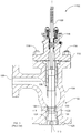
- FIG. 1 illustrates a known fluid valve assembly 100 (e.g., a flow down angle-style control valve) implemented with a known valve trim apparatus 102 that may be used in severe service applications (e.g., severely erosive process fluid, high pressure applications, etc.).
- the example fluid valve assembly 100 includes a valve body 104 that defines a fluid flow passageway 106 between an inlet or side port 108 and an outlet or bottom port 110.
- the inlet 108 is turned at an angle relative to the outlet 110.
- a bonnet 112 is coupled to the valve body 104 via fasteners 114 and couples the valve body 104 to an actuator (not shown).
- the bonnet 112 also houses a packing system 116 to prevent leakage of process fluid to the environment.
- the valve trim apparatus 102 includes a flow control member or valve plug 118 and a valve seat or seat ring 120 disposed within the passageway 106.
- An actuator e.g., a pneumatic actuator, an electric actuator, a hydraulic actuator, etc.
- a seat ring retainer or liner 124 retains the seat ring 120 within the valve body 104 and has an elongated body 126 that extends to protect an interior surface 128 of the outlet 110 from adverse process effects such as, for example, abrasion, erosion, corrosion, etc.
- an actuator drives the valve stem 122 and, thus, the valve plug 118 between a closed position at which the valve plug 118 is sealingly engaged with the seat ring 120 to prevent or restrict fluid flow through the passageway 106 between the inlet 108 and the outlet 110 and a fully open or maximum flow position at which the valve plug 118 is separated from the seat ring 120 to allow fluid flow through the passageway 106 between the inlet 108 and the outlet 110.
- valve trim apparatus 102 may be exposed to severely erosive and/or corrosive fluid conditions that can rapidly wear or cause material loss to surfaces 130 and/or 132 and significantly reduce the operating life of the valve trim apparatus 102.
- the valve plug 118 and/or the seat ring 120 may be exposed to process fluids entrained with particulate (e.g., ceramic catalyst fines) or relatively high viscosity fluids, which can wear or degrade the surfaces 130 and/or 132.
- valve plugs and/or valve seats made of ceramic materials are often employed because ceramic materials have relatively high resistance to erosive or corrosive fluid conditions, thereby increasing the operating life of the valve plugs and/or valve seats.
- the valve plug 118 and/or the seat ring 120 may be made of a ceramic material.
- entrained particulate and/or relatively high viscosity fluid may adhere to the sealing surface 130 and/or the seating surface 132 of the valve plug 118 and/or the seat ring 120 as the valve plug 118 sealingly engages the seat ring 120 in the closed position.
- particulate suspended in the process fluid which may be a relatively high viscosity fluid, flows across the seat ring 120 until the valve plug 118 sealingly engages the seat ring 120.
- Such particulate suspended in the process fluid may adhere to the sealing surface 130 and/or the seating surface 132 as the valve plug 118 sealingly engages the seat ring 120.
- Such particulate which is typically rigid and highly viscous process fluid can prevent the sealing surface 130 of the valve plug 118 from sealingly engaging with the seating surface 132 of the seat ring 120 to provide a tight shut-off, thereby causing leakage through the passageway 106 when the fluid valve 100 is in the closed position.
- a sealing surface of the seat ring 120 and/or the valve plug 118 exposed to particulate and/or highly viscous fluid in this manner becomes ineffective at controlling fluid flow through the fluid valve 100.
- rigid particulate contaminate can damage the sealing surface 130 of the valve plug 118 and/or the seating surface 132 of the seat ring 120.
- the particulate may cause a valve plug and/or a seat ring made of ceramic to fracture, shatter or crack, resulting in a significantly reduced operating life of the valve trim.
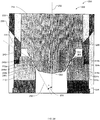
- FIG. 2A illustrates an example fluid valve 200 implemented with an example valve trim apparatus 202 described herein that may be employed in severely erosive or corrosive applications such as, for example, applications involving relatively highly viscous process fluids and/or process fluids entrained with particulate (e.g., ceramic catalyst fines) or other contaminates.
- FIG. 2B illustrates an enlarged portion of the example valve trim apparatus 202 shown in FIG. 2A .
- the fluid valve 200 includes a valve body 204 defining a passageway 206 between an inlet or side port 208 and an outlet or bottom port 210.
- the valve trim apparatus 202 is disposed within the passageway 206 of the valve body 204 to control the fluid flow between the inlet 208 and the outlet 210.
- the inlet 208 is substantially angled relative to the outlet 210.
- a bonnet (not shown) (e.g., similar to the bonnet 112 of FIG. 1 ) may be coupled to the valve body 204 (e.g., via fasteners) and may also couple the valve body 204 to an actuator (not shown).
- the actuator may be operatively coupled to the valve trim apparatus 202 via a valve stem 212.
- the valve trim apparatus 202 includes a flow control member or closure member 214, which is depicted as a valve plug, and a valve seat 216.
- One of the closure member 214 or the valve seat 216 is composed of a metal, carbide (e.g., tungsten carbide) or ceramic material and the other one of the closure member 214 or the valve seat 216 is composed of a material different than the material of the closure member 214.
- the valve seat 216 is composed of a ceramic material (e.g., carbide) and the closure member 214 is composed of stainless steel.
- the closure member 214 is composed of metal, the closure member 214 will yield (e.g., deform) relative to the valve seat 216 composed of ceramic or carbide to provide a relatively tight shut-off.
- the closure member 214 may be composed of a ceramic material and the valve seat 216 may be composed of a metallic material.
- the closure member 214 and the valve seat 216 may be composed of a ceramic material or any other suitable erosion and/or corrosion resistant material(s).
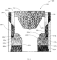
- the valve seat 216 and the closure member 214 form or define at least one cavity 218 when the closure member 214 sealingly engages the valve seat 216. More specifically, the cavity 218 is to receive contaminate (e.g., particulate and/or relatively high viscosity fluid) in contact with (e.g., adhered to) a sealing surface or area 220 of the valve seat 216 and the closure member 214 as the closure member 214 sealingly engages the valve seat 216.
- the cavity 218 may be defined by at least one groove (e.g., an annular groove) formed on the valve seat 216 and/or the closure member 214.
- the valve seat 216 includes the groove or cavity 218 (e.g., an annular groove or cavity) positioned adjacent an annular rib or projection 222 to form or define a raised seating surface 224.
- the cavity or groove 218 receives material or contaminate from the sealing area 220 of the closure member 214 and/or the valve seat 216 as the closure member 214 sealingly engages the valve seat 216.
- the closure member 214 may include at least one groove or channel 218 to form or define at least one raised seating surface 224 or annular rib 222 instead of the valve seat 216.
- each of the valve seat 216 and the closure member 214 includes at least one groove or cavity 218 to form at least one raised seating surface 224 or annular rib 222.
- the valve trim apparatus 202 also includes a cage 226 disposed between the inlet 208 and the outlet 210 to impart certain flow characteristics (e.g., reduce noise and/or cavitation generated by) the process fluid flowing through the fluid valve 200.
- the cage 226 can also facilitate maintenance, removal, and/or replacement of the other components of the valve trim apparatus 202.
- the cage 226 may be composed of a high strength, erosion and/or corrosion resistant material (e.g., stainless steel) and a surface 228 of the cage, which is in fluid communication with the inlet 208, may include (e.g., may be plated by) nitride, carbide and/or any other erosion or corrosion resistant material(s).
- the cage 226 includes a bore 230 to slidably receive the closure member 214 and guide the closure member 214 as an actuator moves the closure member 214 between a first position (e.g., a fully closed position) and a second position (e.g., a fully open position).
- the cage 226 also includes an orifice 232 to provide fluid flow characteristics. The desired fluid flow characteristics are achieved by varying the geometry of the orifice 232.
- the cage 226 may include a plurality of openings having various shapes, sizes, and/or spacing to control the flow, reduce cavitation, and/or reduce noise through the valve.
- the closure member 214 is a valve plug having an outer surface or body portion 234 sized to closely fit within the bore 230 of the cage 226.
- the closure member 214 can slide within the cage 226 between a closed position, in which the closure member 214 obstructs the orifice 232 of the cage 226, and an open position, in which the closure member 214 is clear of (i.e., does not obstruct) at least a portion of the orifice 232.
- the body portion 234 provides a dead-band area or zone 236 dimensioned to block or obstruct fluid flow through the orifice 232 of the cage 226 and prevent or restrict fluid flow across the valve seat 216 over a portion of the stroke as the closure member 214 moves toward the valve seat 216 and before the closure member 214 sealingly engages the valve seat 216.
- the cage 226 and the closure member 214 are configured to provide a fluid flow dead-band to protect the sealing area 220 from erosion, corrosion and damage and/or reduce the amount of contaminate surrounding the sealing area 220 as the closure member 214 moves toward the valve seat 216.
- the valve seat 216 is a seat ring that is clamped adjacent the outlet 210 of the valve body 204.
- the example fluid valve 200 also includes a liner 238 that is clamped between an outlet flange 240 of the valve body 204 and downstream piping (not shown).
- the valve seat 216 is clamped between the cage 226 and the liner 238 and is retained in the valve body 204 via interference fit.
- a seal 241 may be disposed between the seat 216 and the cage 226.
- the liner 238 includes an elongated body 242 that extends to protect a surface or side 244 of the outlet 210 from adverse process effects such as, for example, abrasion, corrosion, etc.
- the liner 238 may be integrally formed with the valve seat 216 as a substantially unitary member or structure. In yet another example, the liner 238 is coupled to the valve body 204 via threads, fasteners and/or other suitable fastening mechanism(s).
- the valve seat 216 includes a plurality of annular protrusions or ribs 222a-b that define cavities or grooves 218a-c (e.g., annular grooves) and a plurality of raised seating surfaces 224a-b.
- a first rib 222a provides a first raised seating surface 224a independent from a second raised seating surface 224b provided by a second rib 222b.
- the raised seating surfaces 224a-b provide redundant sealing surfaces so that if one of the ribs 222a or 222b and/or the raised seating surfaces 224a-b becomes damaged or worn, the other one of the ribs 222a or 222b and/or raised seating surfaces 224a or 224b sealingly engages the closure member 214 to provide a tight shut-off.
- the raised seating surfaces 224a-b or ribs 222a-b are integrally formed with the valve seat 216 as a unitary structure.
- the cavities or grooves 218a-c and/or the ribs 222a-b may be formed via machining or any other suitable manufacturing process(es) to provide the raised seating surfaces 224a-b.
- the annular ribs or protrusions 222a-b include an angled profile 246.
- the angled profile 246 of the annular ribs or protrusions 222a-b includes sloped surfaces 248a-b having a downward inclination away from the inlet 208 and toward the outlet 210.
- the angled profile 246 provides an angle 250 that is approximately sixty degrees relative to a longitudinal axis 252 of the closure member 214.
- the angled profile 246 may provide any other suitable angle.
- each of the sloped surfaces 248a-b may have different angles.
- a surface 248c of the annular groove 218c may have an angled profile different (e.g., a sloped surface at a greater angle) than the angled profile 246 of the surfaces 248a-b.
- the angled profile 246 facilitates movement or collection of contaminate toward the grooves or cavities 218a-c. Additionally or alternatively, the angled profile 246 reduces damage (e.g., cracking) to the raised seating surfaces 224a-b and/or the ribs 222a-b of the valve seat 216 that may caused by a thrust force imparted by an actuator to the valve seat 216 and/or closure member 214 when the fluid valve 200 is in a closed position.
- the closure member 214 also includes a sealing surface 254 that sealingly engages the raised seating surfaces 224a-b of the valve seat 216 when the closure member 214 sealingly engages the valve seat 216.
- the raised seating surfaces 224a-b include an angled profile 256 providing an angle 258 (e.g., a 30 degree angle) that is substantially similar or identical to an angled profile or angle 260 of the sealing surface 254 so that the sealing surface 254 of the closure member 214 matably and/or sealingly engages with the raised seating surfaces 224a-b of the valve seat 216 to provide a tight shut-off.
- the closure member 214 may include at least one groove or channel to form or define at least one raised seating surface or annular rib instead of the valve seat 216, which sealingly engages a seating surface of the valve seat 216.
- each of the valve seat 216 and the closure member 214 includes at least one groove or cavity to form at least one raised seating surface or annular rib.
- an actuator may stroke or move the closure member 214 between a closed position or zero percent (0%) stroke length travel and an open position or 100 percent stroke length travel.
- FIGS. 2A and 2B illustrate the closure member 214 at a closed position 262 (i.e., a zero percent travel of the stroke length) relative to the valve seat 216.
- the sealing surface 254 of the closure member 214 sealingly engages the raised seating surfaces 224a-b of the valve seat 216 to prevent or restrict fluid flow through the passageway 206 between the inlet 208 and the outlet 210.
- Particulate and/or viscous fluid on the raised seating surfaces 224a-b of the valve seat 216 and/or the sealing surface 254 of the closure member 214 will be channeled, wiped away or other wised moved from the sealing area 220 and toward the cavities or grooves 218a-c.
- the cavities or grooves 218a-c receive contaminate as the sealing surface 254 of the closure member 214 sealingly engages the raised seating surfaces 224a-b of the valve seat 216.
- Contaminate in contact with the raised seating surfaces 224a-b and/or the sealing surface 254 will be wiped away from the sealing surface 254 and/or the raised seating surfaces 224a-b and forced or moved (e.g., pushed) toward the grooves or cavities 218a-c by the sealing surface 254 of the closure member 214 as it engages the raised seating surfaces 224a-b.
- the angled profile 256 of the raised seating surfaces 224a-b and/or the angled profile 260 of the sealing surface 254 facilitate collection of contaminate in the cavities or grooves 218a-c.
- the angled profile 246 (e.g., the sloped surfaces 248a-c) of the ribs 222a-b facilitate movement of contaminate (e.g., relatively high viscous fluid, particulate suspended in the fluid flow, etc.) in contact with the sealing area 220 away from and/or toward the cavities or grooves 218a-c as the closure member 214 sealingly engages the valve seat 216. If one of the raised seating surfaces 224a-b become damaged or worn, the other one of the raised seating surfaces 224a-b provides a seal when the closure member 214 engages the valve seat 216. Thus, the raised seating surfaces 224a-b provide redundant sealing.
- contaminate e.g., relatively high viscous fluid, particulate suspended in the fluid flow, etc.
- the example valve trim apparatus 202 provides an effective fluid flow dead-band to reduce particulate or contaminate flowing across and/or adhering to the sealing area 220 as the closure member 214 moves from an open position 300 (i.e., 100 percent travel of the stroke length) as shown in FIG.3 and the closed position 262 shown in FIGS. 2A and 2B .
- the closure member 214 is separated from the valve seat 216 to enable a maximum fluid flow through the passageway 206 of the valve body 204 between the inlet 208 and the outlet 210.
- Relatively high viscosity fluid and/or fluid entrained with particulate flows through the passageway 206 across the valve seat 216.
- the valve seat 216 which may be composed of ceramic material, resists erosion and corrosion as particulate suspended in process fluid flows across the valve seat 216.
- the actuator moves the closure member 214 toward the valve seat 216.
- the closure member 214 slides within the cage 226 between the open position 300, in which the body portion 234 of the closure member 214 is clear of at least a portion of the orifice 232 and the closed position 262 ( FIGS. 2A and 2B ), in which the body portion 234 of the closure member 214 obstructs the orifice 232 of the cage 226.
- FIG. 4 illustrates the closure member 214 at an intermediate position 400 as the closure member 214 moves between the open position 300 shown in FIG. 3 and the closed position 262 shown in FIGS. 2A and 2B .
- the dead-band area or zone 236 of the closure member 214 obstructs or blocks the orifice 232 of the cage 226 to restrict or prevent fluid flow across the valve seat 216 before the sealing surface 254 of the closure member 214 sealingly engages the raised seating surfaces 224a-b of the valve seat 216.
- the fluid flow dead-band zone or area 236 of the closure member 214 moves relative to and/or adjacent the opening of the cage 226 to provide a dead-band stroke length travel to the overall stroke length travel of the closure member 214.
- the dead-band zone or area 236 of the body portion 234 and/or the sealing surface 254 may be configured to provide a predetermined fluid flow dead-band prior to when the fluid valve 200 is in the fully closed position 262 as shown in FIGS. 2A and 2B .
- the orifice 232 of the cage 226 may be dimensioned or sized to provide an effective dead-band stroke length travel.
- the dead-band zone or area 236 restricts or blocks particulate suspended within the fluid flow before the closure member 214 sealingly engages the valve seat 216 in the closed position 262. Restricting the fluid flow across the valve seat 216 before the closure member 214 sealingly engages the valve seat 216 significantly reduces a residual quantity of contaminate or particulate suspended in the flowing fluid from gathering or adhering to the sealing area 220 of the valve trim apparatus 202 as the closure member 214 is moving toward the valve seat 216. Further, the pressure of the fluid at the outlet 210 moves or pushes the particulate away from the valve seat 216 and/or the closure member 214 and toward the outlet 210 of the fluid valve 200.
- a relatively high pressure fluid at the inlet 208 does not flow across the sealing surface 254 of the closure member 214 and/or the raised seating surfaces 224a-b of the valve seat 216. Reducing or minimizing a relatively high pressure fluid across the sealing area 220 significantly increases the operating life of the sealing surface 254 and/or the raised seating surfaces 224a-b and, thus, the valve trim apparatus 202.
- valve trim examples are advantageous in severely erosive fluids such as, for example, relatively high viscosity fluids and/or fluids containing particulate (e.g., ceramic catalyst fines), which can prevent the closure member 214 and the valve seat 216 from properly sealingly engaging, thereby causing leakage of process fluid through the passageway 206 when the fluid valve 200 is in the closed position 262.
- the closure member 214 and the valve seat 216 cooperatively engage to define a cavity and move contaminate from a sealing surface of the valve seat 216 or valve closure member 214 to the cavity as the valve closure member 214 moves toward a sealing engagement with the valve seat 216.
- the valve trim apparatus is configured to wipe away particulate, contaminate and/or high viscosity fluids from the sealing area 220 when the closure member 214 sealingly engages the valve seat 216. Further, an effective fluid flow dead-band reduces contaminant (e.g., relatively high viscous fluid or a particulate suspended in the fluid) from adhering to the sealing area 220 of the valve seat 216 and/or the closure member 214 as the closure member 214 is moving toward the valve seat 216.
- contaminant e.g., relatively high viscous fluid or a particulate suspended in the fluid
- angle-style valves advantageously allow for easy draining because the valve body or flow path of such valves does not have any pockets or areas that allow accumulation of fluid and/or residue.
- angle-style control valves are typically used in the chemical and petroleum industries, which often require control of residual oils or other liquids with coking properties.
- the example valve trim apparatus described herein are not limited to use with angle-style fluid valves.
- fluid valves such as, for example, globe valves, rotary valves, linear valves, etc., may be employed.
Claims (13)
- Ventilgarnitur (202), umfassend:einen Ventilsitz (216); undein Schließteil (214), um den Ventilsitz (216) operativ in Eingriff zu nehmen;wobei das Schließteil (214) oder der Ventilsitz (216) mehrere ringförmige Rippen (222a, 222b) aufweist; undder Ventilsitz (216) oder das Schließteil (214) mindestens eine Nut (218a, 218b, 218c) definiert, die zwischen mindestens zweien der ringförmigen Rippen (222a, 222b) angeordnet ist, um Verschmutzungen aufzunehmen, die in Kontakt mit einer Dichtungsfläche (254) von jeweils dem anderen Element, dem Schließteil (214) oder dem Ventilsitz (216) stehen, wenn das Schließteil (214) abdichtend mit dem Ventilsitz (216) in Eingriff ist, wobei jede der mindestens zwei ringförmigen Rippen (222a, 222b) eine erhöhte Sitzfläche (224a, 224b) aufweist; undwobei die ringförmigen Rippen (222a, 222b) ein abgewinkeltes Profil (246) haben, um eine Ansammlung der Verschmutzungen in der mindestens eine Nut (218a, 218b, 218c) zu erleichtern; undeinen Käfig (226), der operativ mit dem Schließteil (214) verbunden ist, so, dass eine Fluidströmung durch den Käfig (226) im Wesentlichen blockiert ist, wenn sich das Schließteil (214) zum Ventilsitz (216) bewegt, und bevor das Schließteil (214) abdichtend mit dem Ventilsitz (216) in Eingriff ist;und wobei ein Winkel (260) der Dichtungsfläche (254) im Wesentlichen ähnlich einem Winkel (258) ist, der durch ein abgewinkeltes Profil (256) der erhöhten Sitzflächen (224a, 224b) bereitgestellt wird, derart, dass die Dichtungsfläche (254) einen abdichtenden Eingriff mit den erhöhten Sitzflächen (224a, 224b) eingeht, um eine dichte Absperrung bereitzustellen.
- Ventilgarnitur nach Anspruch 1, wobei die ringförmigen Rippen (222a, 222b) strukturiert sind, um redundante Dichtungsflächen bereitzustellen.
- Ventilgarnitur nach Anspruch 1, wobei die Verschmutzungen eine Partikelmasse oder ein relativ hochviskoses Fluid umfassen, die bzw. das in Kontakt mit der Dichtungsfläche (254) des Ventilsitzes (216) des Schließteils (214) steht, bevor sie bzw. es in die mindestens eine Nut (218a, 218b, 218c) aufgenommen wird.
- Ventilgarnitur nach Anspruch 1, wobei es sich bei dem Ventilsitz (216) um einen Sitzring handelt und die mehreren ringförmigen Rippen (222a, 222b) einstückig mit dem Sitzring sind, und/oder wobei es sich bei dem Schließteil (214) um einen Stopfen handelt und die mehreren ringförmigen Rippen (222a, 222b) einstückig mit dem Stopfen sind.
- Ventilgarnitur nach Anspruch 4, wobei der Sitzring angrenzend an eine Auslassöffnung (210) eines Ventilkörpers (204) festgeklemmt werden soll.
- Ventilgarnitur nach Anspruch 1, wobei das abgewinkelte Profil (246) der Rippen (222a, 222b) einen Winkel von ca. sechzig Grad in Bezug auf eine Längsachse (252) des Schließteils (214) definiert.
- Ventilgarnitur nach Anspruch 1, wobei das Schließteil (214) oder der Ventilsitz (216) Metall, Carbid oder Keramik umfasst, und das jeweils andere Element, das Schließteil (214) oder der Ventilsitz (216) ein Material umfasst, das sich von demjenigen des Schließteils (214) unterscheidet.
- Ventilgarnitur nach Anspruch 1, wobei die mehreren ringförmigen Rippen (222a, 222b) dazu ausgelegt sind, die Verschmutzungen von der Dichtungsfläche (254) des Ventilsitzes (216) oder des Schließteils (214) zu der mindestens einen Nut (218a, 218b, 218c) zu bewegen.
- Ventilgarnitur nach Anspruch 8, wobei die ringförmigen Rippen (222a, 222b) strukturiert sind, um redundante Dichtungsflächen bereitzustellen.
- Ventilgarnitur nach Anspruch 1, wobei der Käfig (226) dazu ausgelegt ist, eine Strömungstotzone (236) bereitzustellen, um die Dichtungsfläche (254) vor Erosion zu schützen.
- Ventilgarnitur nach Anspruch 10, wobei die Totzone (236) in der Fluidströmung suspendierte Partikel drosselt, bevor das Schließteil (214) in der geschlossenen Position einen abdichtenden Eingriff mit dem Ventilsitz (216) herstellt.
- Ventilgarnitur nach Anspruch 1, wobei das Schließteil (214) einen Körperabschnitt (234) umfasst, der eine Fluidströmung über den Ventilsitz (216) drosselt, bevor die Dichtungsfläche (254) abdichtend mit dem Ventilsitz (216) in Eingriff ist.
- Ventilgarnitur nach Anspruch 12, wobei der Käfig (226) eine Mündung (232) umfasst, und wobei der Körperabschnitt (234) des Schließteils (214) dazu dimensioniert ist, eine Fluidströmung durch die Mündung (232) und über den Ventilsitz (216) zu blockieren, bevor die Dichtungsfläche (254) abdichtend mit dem Ventilsitz (216) in Eingriff ist.
Applications Claiming Priority (1)
| Application Number | Priority Date | Filing Date | Title |
|---|---|---|---|
| PCT/CN2010/073212 WO2011147078A1 (en) | 2010-05-25 | 2010-05-25 | Valve trim apparatus having cavity to receive contaminates from sealing surface |
Publications (3)
| Publication Number | Publication Date |
|---|---|
| EP2577125A1 EP2577125A1 (de) | 2013-04-10 |
| EP2577125A4 EP2577125A4 (de) | 2016-12-07 |
| EP2577125B1 true EP2577125B1 (de) | 2019-10-23 |
Family
ID=45003200
Family Applications (1)
| Application Number | Title | Priority Date | Filing Date |
|---|---|---|---|
| EP10851950.5A Active EP2577125B1 (de) | 2010-05-25 | 2010-05-25 | Ventilgarnitur mit vertiefung zur aufnahme von verschmutzungen aus einer dichtungsfläche |
Country Status (7)
| Country | Link |
|---|---|
| US (1) | US9115814B2 (de) |
| EP (1) | EP2577125B1 (de) |
| JP (1) | JP5684902B2 (de) |
| CN (1) | CN103119347B (de) |
| CA (1) | CA2800373C (de) |
| RU (1) | RU2542728C2 (de) |
| WO (1) | WO2011147078A1 (de) |
Families Citing this family (24)
| Publication number | Priority date | Publication date | Assignee | Title |
|---|---|---|---|---|
| US20140034155A1 (en) * | 2012-07-31 | 2014-02-06 | Fairchild Industrial Products Company | Valve Seat For A Pressure Regulator |
| US9605762B2 (en) | 2012-08-17 | 2017-03-28 | Uhde High Pressure Technologies Gmbh | High-pressure valve |
| DE102013219439A1 (de) * | 2013-09-26 | 2014-11-27 | Continental Automotive Gmbh | Ventileinrichtung für eine Hochdruckpumpe |
| JP6282439B2 (ja) * | 2013-10-30 | 2018-02-21 | 愛三工業株式会社 | 減圧弁 |
| CN104847902B (zh) * | 2014-02-14 | 2018-12-04 | 欧洲技术设于伊特根的三聚氰氨-卢森堡-分支机构 | 角阀 |
| DE102014110246A1 (de) * | 2014-07-21 | 2016-01-21 | Samson Ag | Stellarmatur |
| US9915353B2 (en) | 2014-10-28 | 2018-03-13 | Fisher Controls International Llc | Choked flow valve with clamped seat ring |
| KR200480535Y1 (ko) | 2015-02-03 | 2016-06-03 | 김형호 | 복층 시트부 구조를 갖는 글로브 밸브 |
| US9909670B2 (en) * | 2015-03-04 | 2018-03-06 | Praxair Technology, Inc. | Modified vacuum actuated valve assembly and sealing mechanism for improved flow stability for fluids sub-atmospherically dispensed from storage and delivery systems |
| US11092260B2 (en) | 2015-10-16 | 2021-08-17 | Emerson Process Management (Tianjin) Valves Co., Ltd | Multiple stage anti-surge valves |
| CN105299303B (zh) * | 2015-11-02 | 2018-09-04 | 合肥通用机械研究院有限公司 | 一种高压排污气动阀 |
| JP6654644B2 (ja) * | 2015-11-06 | 2020-02-26 | 株式会社日立製作所 | 弁構造並びにこれを有する油圧機器及び流体機械並びに機械 |
| CA3030405A1 (en) * | 2016-07-13 | 2018-01-18 | Stone Mountain Technologies, Inc. | Electronic expansion valves having multiple orifice plates |
| US10151397B2 (en) * | 2016-11-30 | 2018-12-11 | Fisher Controls International Llc | Composite valve plugs and related methods |
| US10480661B2 (en) * | 2017-09-06 | 2019-11-19 | Baker Hughes, A Ge Company, Llc | Leak rate reducing sealing device |
| US10655743B2 (en) * | 2017-09-29 | 2020-05-19 | Fisher Controls International Llc | Carbide insert assembly having a fused retainer |
| US10371265B2 (en) * | 2017-11-01 | 2019-08-06 | Fisher Controls International Llc | Process control valve and plug |
| CN112166270B (zh) * | 2018-05-03 | 2023-06-16 | D·K·西廷 | 带密封件的阀和阀座 |
| US10627010B2 (en) * | 2018-07-30 | 2020-04-21 | William Xiaoguang Sun | Method and apparatus for isolating water valves |
| JP7328775B2 (ja) * | 2019-03-26 | 2023-08-17 | 株式会社キッツエスシーティー | ダイヤフラムバルブ |
| US10830358B2 (en) * | 2019-04-15 | 2020-11-10 | Fisher Controls International Llc | Valve trim having adjustable fluid flow characteristics and related methods |
| KR102103737B1 (ko) * | 2019-04-17 | 2020-04-24 | (주)하이플럭스 | 스템용 캐리어를 포함한 밸브 |
| DE102020112308A1 (de) * | 2020-05-06 | 2021-11-11 | Hammelmann GmbH | Druckregelventil |
| GB2617334A (en) * | 2022-04-04 | 2023-10-11 | Weir Minerals Netherlands Bv | Valve |
Citations (1)
| Publication number | Priority date | Publication date | Assignee | Title |
|---|---|---|---|---|
| US6772993B1 (en) * | 2003-02-18 | 2004-08-10 | Control Components, Inc. | Plug and seal assembly |
Family Cites Families (28)
| Publication number | Priority date | Publication date | Assignee | Title |
|---|---|---|---|---|
| US1560235A (en) * | 1925-01-05 | 1925-11-03 | Hinsch Albert Otto | Valve |
| US2114858A (en) * | 1936-08-12 | 1938-04-19 | Gen Electric | Throttle valve |
| DE1037379B (de) * | 1955-01-12 | 1958-08-21 | Max Kastl | Druckspueler, insbesondere Klosettdruckspueler, mit Gegendruckkammer |
| JPS4412467Y1 (de) * | 1967-02-23 | 1969-05-23 | ||
| JPS521136B1 (de) | 1968-06-20 | 1977-01-12 | ||
| GB1441295A (en) * | 1972-10-28 | 1976-06-30 | Messerschmitt Boelkow Blohm | Control valve for pulsed rocket propulsion units |
| JPS50132721U (de) * | 1974-04-16 | 1975-10-31 | ||
| JPS5313946Y2 (de) * | 1974-04-16 | 1978-04-14 | ||
| JPS5460317U (de) * | 1977-10-06 | 1979-04-26 | ||
| JPS54159225U (de) * | 1978-04-27 | 1979-11-07 | ||
| IT1186428B (it) * | 1985-12-12 | 1987-11-26 | Tetra Dev Co | Valvola per controllo e intercettazione di flussi,contenenti particelle |
| JPS63109077U (de) | 1987-01-06 | 1988-07-13 | ||
| CN1071496A (zh) * | 1991-10-14 | 1993-04-28 | 王佐才 | 闸阀型截止阀 |
| CN2106272U (zh) | 1991-10-14 | 1992-06-03 | 王佐才 | 闸阀型截止阀 |
| US6105610A (en) * | 1998-02-13 | 2000-08-22 | Liquid Metronics Incorporated | Cartridge valve with triple sequential seal |
| JPH11336905A (ja) * | 1998-05-28 | 1999-12-07 | Ckd Corp | バルブのシール構造 |
| US6135523A (en) * | 1999-05-18 | 2000-10-24 | Pratt; David W. | Bailer having leak-inhibiting seal |
| US6502770B2 (en) * | 2000-12-29 | 2003-01-07 | Siemens Automotive Corporation | Modular fuel injector having a snap-on orifice disk retainer and having a terminal connector interconnecting an electromagnetic actuator with an electrical terminal |
| US6805162B2 (en) * | 2002-08-15 | 2004-10-19 | Control Components, Inc. | Erosion reducing valve plug and seat ring |
| RU2249742C2 (ru) * | 2003-03-20 | 2005-04-10 | Андреев Александр Павлович | Клапан регулирующий |
| EP1493534A1 (de) * | 2003-07-01 | 2005-01-05 | Maschinenfabrik Gehring GmbH & Co. KG | Verfahren zur Herstellung von Ventilsitzen und Ventil mit einem im wesentlichen kegelförmigen Ventilsitz |
| US20060096643A1 (en) * | 2004-11-10 | 2006-05-11 | Mccarty Michael W | Seal assembly for a fluid pressure control device |
| RU2285176C2 (ru) * | 2004-12-20 | 2006-10-10 | Александр Павлович Андреев | Клапан регулирующий |
| JP2007155102A (ja) | 2005-12-08 | 2007-06-21 | S-Park:Kk | 圧力調整弁 |
| JP4237781B2 (ja) | 2006-06-29 | 2009-03-11 | シーケーディ株式会社 | 流量制御弁 |
| CN201265656Y (zh) * | 2008-05-14 | 2009-07-01 | 上海阀门厂有限公司 | 矿浆调节阀 |
| KR100986070B1 (ko) * | 2008-06-05 | 2010-10-07 | 기아자동차주식회사 | 연료 분사 장치 |
| US8037897B2 (en) * | 2008-06-20 | 2011-10-18 | Mcintire William Ray | Valve apparatus |
-
2010
- 2010-05-25 WO PCT/CN2010/073212 patent/WO2011147078A1/en active Application Filing
- 2010-05-25 CN CN201080067978.XA patent/CN103119347B/zh active Active
- 2010-05-25 EP EP10851950.5A patent/EP2577125B1/de active Active
- 2010-05-25 JP JP2013511496A patent/JP5684902B2/ja active Active
- 2010-05-25 US US13/700,106 patent/US9115814B2/en active Active
- 2010-05-25 RU RU2012155148/06A patent/RU2542728C2/ru active
- 2010-05-25 CA CA2800373A patent/CA2800373C/en active Active
Patent Citations (1)
| Publication number | Priority date | Publication date | Assignee | Title |
|---|---|---|---|---|
| US6772993B1 (en) * | 2003-02-18 | 2004-08-10 | Control Components, Inc. | Plug and seal assembly |
Also Published As
| Publication number | Publication date |
|---|---|
| EP2577125A4 (de) | 2016-12-07 |
| RU2542728C2 (ru) | 2015-02-27 |
| WO2011147078A1 (en) | 2011-12-01 |
| EP2577125A1 (de) | 2013-04-10 |
| JP5684902B2 (ja) | 2015-03-18 |
| CA2800373C (en) | 2019-04-16 |
| RU2012155148A (ru) | 2014-06-27 |
| US9115814B2 (en) | 2015-08-25 |
| JP2013526692A (ja) | 2013-06-24 |
| CN103119347B (zh) | 2015-10-14 |
| BR112012029942A2 (pt) | 2020-07-14 |
| CA2800373A1 (en) | 2011-12-01 |
| CN103119347A (zh) | 2013-05-22 |
| US20130068987A1 (en) | 2013-03-21 |
Similar Documents
| Publication | Publication Date | Title |
|---|---|---|
| EP2577125B1 (de) | Ventilgarnitur mit vertiefung zur aufnahme von verschmutzungen aus einer dichtungsfläche | |
| EP2677219B1 (de) | Dichtungsanordnungen zur Verwendung mit Flüssigkeitsventilen | |
| EP2547936B1 (de) | Keramischer einbaudrossel eines ventils mit geschützten absperrflächen | |
| US10683941B2 (en) | Black-powder-resistant through conduit valve | |
| AU2018203032B2 (en) | Media control valve | |
| EP2772671A1 (de) | Dichtungsanordnung zur Verwendung mit Ventilen mit zweiteiligem Käfig | |
| EP2598778A1 (de) | Ventilsitzvorrichtung für flüssigkeitsventile | |
| AU2012333224A1 (en) | Media control valve | |
| EP2300741B1 (de) | Ventilinnenteilrückhaltevorrichtung | |
| US20150362079A1 (en) | Media Control Valve | |
| BR112012029942B1 (pt) | Aparelho de guarnição de válvula tendo cavidade para receber contaminantes de superfície de vedação | |
| CN116816947A (zh) | 包括硬化顶端的阀塞 |
Legal Events
| Date | Code | Title | Description |
|---|---|---|---|
| PUAI | Public reference made under article 153(3) epc to a published international application that has entered the european phase |
Free format text: ORIGINAL CODE: 0009012 |
|
| 17P | Request for examination filed |
Effective date: 20121128 |
|
| AK | Designated contracting states |
Kind code of ref document: A1 Designated state(s): AL AT BE BG CH CY CZ DE DK EE ES FI FR GB GR HR HU IE IS IT LI LT LU LV MC MK MT NL NO PL PT RO SE SI SK SM TR |
|
| DAX | Request for extension of the european patent (deleted) | ||
| RA4 | Supplementary search report drawn up and despatched (corrected) |
Effective date: 20161104 |
|
| RIC1 | Information provided on ipc code assigned before grant |
Ipc: F16K 25/04 20060101AFI20161028BHEP Ipc: F16K 3/22 20060101ALI20161028BHEP Ipc: F16K 1/26 20060101ALI20161028BHEP |
|
| STAA | Information on the status of an ep patent application or granted ep patent |
Free format text: STATUS: EXAMINATION IS IN PROGRESS |
|
| 17Q | First examination report despatched |
Effective date: 20180314 |
|
| REG | Reference to a national code |
Ref country code: DE Ref legal event code: R079 Ref document number: 602010061680 Country of ref document: DE Free format text: PREVIOUS MAIN CLASS: F16K0025040000 Ipc: F16K0001420000 |
|
| GRAP | Despatch of communication of intention to grant a patent |
Free format text: ORIGINAL CODE: EPIDOSNIGR1 |
|
| STAA | Information on the status of an ep patent application or granted ep patent |
Free format text: STATUS: GRANT OF PATENT IS INTENDED |
|
| RIC1 | Information provided on ipc code assigned before grant |
Ipc: F16K 1/42 20060101AFI20190401BHEP Ipc: F16K 3/24 20060101ALI20190401BHEP Ipc: F16K 25/04 20060101ALI20190401BHEP |
|
| INTG | Intention to grant announced |
Effective date: 20190506 |
|
| GRAS | Grant fee paid |
Free format text: ORIGINAL CODE: EPIDOSNIGR3 |
|
| GRAA | (expected) grant |
Free format text: ORIGINAL CODE: 0009210 |
|
| STAA | Information on the status of an ep patent application or granted ep patent |
Free format text: STATUS: THE PATENT HAS BEEN GRANTED |
|
| AK | Designated contracting states |
Kind code of ref document: B1 Designated state(s): AL AT BE BG CH CY CZ DE DK EE ES FI FR GB GR HR HU IE IS IT LI LT LU LV MC MK MT NL NO PL PT RO SE SI SK SM TR |
|
| REG | Reference to a national code |
Ref country code: GB Ref legal event code: FG4D |
|
| REG | Reference to a national code |
Ref country code: CH Ref legal event code: EP |
|
| REG | Reference to a national code |
Ref country code: IE Ref legal event code: FG4D |
|
| REG | Reference to a national code |
Ref country code: DE Ref legal event code: R096 Ref document number: 602010061680 Country of ref document: DE |
|
| REG | Reference to a national code |
Ref country code: AT Ref legal event code: REF Ref document number: 1194016 Country of ref document: AT Kind code of ref document: T Effective date: 20191115 |
|
| REG | Reference to a national code |
Ref country code: SE Ref legal event code: TRGR |
|
| REG | Reference to a national code |
Ref country code: FI Ref legal event code: FGE |
|
| REG | Reference to a national code |
Ref country code: NL Ref legal event code: MP Effective date: 20191023 |
|
| REG | Reference to a national code |
Ref country code: LT Ref legal event code: MG4D |
|
| PG25 | Lapsed in a contracting state [announced via postgrant information from national office to epo] |
Ref country code: LT Free format text: LAPSE BECAUSE OF FAILURE TO SUBMIT A TRANSLATION OF THE DESCRIPTION OR TO PAY THE FEE WITHIN THE PRESCRIBED TIME-LIMIT Effective date: 20191023 Ref country code: PL Free format text: LAPSE BECAUSE OF FAILURE TO SUBMIT A TRANSLATION OF THE DESCRIPTION OR TO PAY THE FEE WITHIN THE PRESCRIBED TIME-LIMIT Effective date: 20191023 Ref country code: GR Free format text: LAPSE BECAUSE OF FAILURE TO SUBMIT A TRANSLATION OF THE DESCRIPTION OR TO PAY THE FEE WITHIN THE PRESCRIBED TIME-LIMIT Effective date: 20200124 Ref country code: NO Free format text: LAPSE BECAUSE OF FAILURE TO SUBMIT A TRANSLATION OF THE DESCRIPTION OR TO PAY THE FEE WITHIN THE PRESCRIBED TIME-LIMIT Effective date: 20200123 Ref country code: NL Free format text: LAPSE BECAUSE OF FAILURE TO SUBMIT A TRANSLATION OF THE DESCRIPTION OR TO PAY THE FEE WITHIN THE PRESCRIBED TIME-LIMIT Effective date: 20191023 Ref country code: ES Free format text: LAPSE BECAUSE OF FAILURE TO SUBMIT A TRANSLATION OF THE DESCRIPTION OR TO PAY THE FEE WITHIN THE PRESCRIBED TIME-LIMIT Effective date: 20191023 Ref country code: LV Free format text: LAPSE BECAUSE OF FAILURE TO SUBMIT A TRANSLATION OF THE DESCRIPTION OR TO PAY THE FEE WITHIN THE PRESCRIBED TIME-LIMIT Effective date: 20191023 Ref country code: BG Free format text: LAPSE BECAUSE OF FAILURE TO SUBMIT A TRANSLATION OF THE DESCRIPTION OR TO PAY THE FEE WITHIN THE PRESCRIBED TIME-LIMIT Effective date: 20200123 Ref country code: PT Free format text: LAPSE BECAUSE OF FAILURE TO SUBMIT A TRANSLATION OF THE DESCRIPTION OR TO PAY THE FEE WITHIN THE PRESCRIBED TIME-LIMIT Effective date: 20200224 |
|
| PG25 | Lapsed in a contracting state [announced via postgrant information from national office to epo] |
Ref country code: IS Free format text: LAPSE BECAUSE OF FAILURE TO SUBMIT A TRANSLATION OF THE DESCRIPTION OR TO PAY THE FEE WITHIN THE PRESCRIBED TIME-LIMIT Effective date: 20200224 Ref country code: HR Free format text: LAPSE BECAUSE OF FAILURE TO SUBMIT A TRANSLATION OF THE DESCRIPTION OR TO PAY THE FEE WITHIN THE PRESCRIBED TIME-LIMIT Effective date: 20191023 |
|
| PG25 | Lapsed in a contracting state [announced via postgrant information from national office to epo] |
Ref country code: AL Free format text: LAPSE BECAUSE OF FAILURE TO SUBMIT A TRANSLATION OF THE DESCRIPTION OR TO PAY THE FEE WITHIN THE PRESCRIBED TIME-LIMIT Effective date: 20191023 |
|
| REG | Reference to a national code |
Ref country code: DE Ref legal event code: R097 Ref document number: 602010061680 Country of ref document: DE |
|
| PG2D | Information on lapse in contracting state deleted |
Ref country code: IS |
|
| PG25 | Lapsed in a contracting state [announced via postgrant information from national office to epo] |
Ref country code: EE Free format text: LAPSE BECAUSE OF FAILURE TO SUBMIT A TRANSLATION OF THE DESCRIPTION OR TO PAY THE FEE WITHIN THE PRESCRIBED TIME-LIMIT Effective date: 20191023 Ref country code: DK Free format text: LAPSE BECAUSE OF FAILURE TO SUBMIT A TRANSLATION OF THE DESCRIPTION OR TO PAY THE FEE WITHIN THE PRESCRIBED TIME-LIMIT Effective date: 20191023 Ref country code: RO Free format text: LAPSE BECAUSE OF FAILURE TO SUBMIT A TRANSLATION OF THE DESCRIPTION OR TO PAY THE FEE WITHIN THE PRESCRIBED TIME-LIMIT Effective date: 20191023 Ref country code: CZ Free format text: LAPSE BECAUSE OF FAILURE TO SUBMIT A TRANSLATION OF THE DESCRIPTION OR TO PAY THE FEE WITHIN THE PRESCRIBED TIME-LIMIT Effective date: 20191023 Ref country code: IS Free format text: LAPSE BECAUSE OF FAILURE TO SUBMIT A TRANSLATION OF THE DESCRIPTION OR TO PAY THE FEE WITHIN THE PRESCRIBED TIME-LIMIT Effective date: 20200223 |
|
| REG | Reference to a national code |
Ref country code: AT Ref legal event code: MK05 Ref document number: 1194016 Country of ref document: AT Kind code of ref document: T Effective date: 20191023 |
|
| PLBE | No opposition filed within time limit |
Free format text: ORIGINAL CODE: 0009261 |
|
| STAA | Information on the status of an ep patent application or granted ep patent |
Free format text: STATUS: NO OPPOSITION FILED WITHIN TIME LIMIT |
|
| PG25 | Lapsed in a contracting state [announced via postgrant information from national office to epo] |
Ref country code: IT Free format text: LAPSE BECAUSE OF FAILURE TO SUBMIT A TRANSLATION OF THE DESCRIPTION OR TO PAY THE FEE WITHIN THE PRESCRIBED TIME-LIMIT Effective date: 20191023 Ref country code: SK Free format text: LAPSE BECAUSE OF FAILURE TO SUBMIT A TRANSLATION OF THE DESCRIPTION OR TO PAY THE FEE WITHIN THE PRESCRIBED TIME-LIMIT Effective date: 20191023 Ref country code: SM Free format text: LAPSE BECAUSE OF FAILURE TO SUBMIT A TRANSLATION OF THE DESCRIPTION OR TO PAY THE FEE WITHIN THE PRESCRIBED TIME-LIMIT Effective date: 20191023 |
|
| 26N | No opposition filed |
Effective date: 20200724 |
|
| PG25 | Lapsed in a contracting state [announced via postgrant information from national office to epo] |
Ref country code: SI Free format text: LAPSE BECAUSE OF FAILURE TO SUBMIT A TRANSLATION OF THE DESCRIPTION OR TO PAY THE FEE WITHIN THE PRESCRIBED TIME-LIMIT Effective date: 20191023 Ref country code: AT Free format text: LAPSE BECAUSE OF FAILURE TO SUBMIT A TRANSLATION OF THE DESCRIPTION OR TO PAY THE FEE WITHIN THE PRESCRIBED TIME-LIMIT Effective date: 20191023 |
|
| PG25 | Lapsed in a contracting state [announced via postgrant information from national office to epo] |
Ref country code: MC Free format text: LAPSE BECAUSE OF FAILURE TO SUBMIT A TRANSLATION OF THE DESCRIPTION OR TO PAY THE FEE WITHIN THE PRESCRIBED TIME-LIMIT Effective date: 20191023 Ref country code: CH Free format text: LAPSE BECAUSE OF NON-PAYMENT OF DUE FEES Effective date: 20200531 Ref country code: LI Free format text: LAPSE BECAUSE OF NON-PAYMENT OF DUE FEES Effective date: 20200531 |
|
| REG | Reference to a national code |
Ref country code: BE Ref legal event code: MM Effective date: 20200531 |
|
| PG25 | Lapsed in a contracting state [announced via postgrant information from national office to epo] |
Ref country code: LU Free format text: LAPSE BECAUSE OF NON-PAYMENT OF DUE FEES Effective date: 20200525 |
|
| PG25 | Lapsed in a contracting state [announced via postgrant information from national office to epo] |
Ref country code: IE Free format text: LAPSE BECAUSE OF NON-PAYMENT OF DUE FEES Effective date: 20200525 |
|
| PG25 | Lapsed in a contracting state [announced via postgrant information from national office to epo] |
Ref country code: BE Free format text: LAPSE BECAUSE OF NON-PAYMENT OF DUE FEES Effective date: 20200531 |
|
| PG25 | Lapsed in a contracting state [announced via postgrant information from national office to epo] |
Ref country code: TR Free format text: LAPSE BECAUSE OF FAILURE TO SUBMIT A TRANSLATION OF THE DESCRIPTION OR TO PAY THE FEE WITHIN THE PRESCRIBED TIME-LIMIT Effective date: 20191023 Ref country code: MT Free format text: LAPSE BECAUSE OF FAILURE TO SUBMIT A TRANSLATION OF THE DESCRIPTION OR TO PAY THE FEE WITHIN THE PRESCRIBED TIME-LIMIT Effective date: 20191023 Ref country code: CY Free format text: LAPSE BECAUSE OF FAILURE TO SUBMIT A TRANSLATION OF THE DESCRIPTION OR TO PAY THE FEE WITHIN THE PRESCRIBED TIME-LIMIT Effective date: 20191023 |
|
| PG25 | Lapsed in a contracting state [announced via postgrant information from national office to epo] |
Ref country code: MK Free format text: LAPSE BECAUSE OF FAILURE TO SUBMIT A TRANSLATION OF THE DESCRIPTION OR TO PAY THE FEE WITHIN THE PRESCRIBED TIME-LIMIT Effective date: 20191023 |
|
| P01 | Opt-out of the competence of the unified patent court (upc) registered |
Effective date: 20230525 |
|
| PGFP | Annual fee paid to national office [announced via postgrant information from national office to epo] |
Ref country code: FR Payment date: 20230420 Year of fee payment: 14 Ref country code: DE Payment date: 20230419 Year of fee payment: 14 |
|
| PGFP | Annual fee paid to national office [announced via postgrant information from national office to epo] |
Ref country code: SE Payment date: 20230419 Year of fee payment: 14 Ref country code: FI Payment date: 20230419 Year of fee payment: 14 |
|
| PGFP | Annual fee paid to national office [announced via postgrant information from national office to epo] |
Ref country code: GB Payment date: 20230420 Year of fee payment: 14 |