EP2576397B1 - Fully autonomous lashing platform - Google Patents
Fully autonomous lashing platform Download PDFInfo
- Publication number
- EP2576397B1 EP2576397B1 EP11708684.3A EP11708684A EP2576397B1 EP 2576397 B1 EP2576397 B1 EP 2576397B1 EP 11708684 A EP11708684 A EP 11708684A EP 2576397 B1 EP2576397 B1 EP 2576397B1
- Authority
- EP
- European Patent Office
- Prior art keywords
- lashing platform
- line
- gas storage
- lashing
- platform
- Prior art date
- Legal status (The legal status is an assumption and is not a legal conclusion. Google has not performed a legal analysis and makes no representation as to the accuracy of the status listed.)
- Active
Links
Images
Classifications
-
- B—PERFORMING OPERATIONS; TRANSPORTING
- B65—CONVEYING; PACKING; STORING; HANDLING THIN OR FILAMENTARY MATERIAL
- B65D—CONTAINERS FOR STORAGE OR TRANSPORT OF ARTICLES OR MATERIALS, e.g. BAGS, BARRELS, BOTTLES, BOXES, CANS, CARTONS, CRATES, DRUMS, JARS, TANKS, HOPPERS, FORWARDING CONTAINERS; ACCESSORIES, CLOSURES, OR FITTINGS THEREFOR; PACKAGING ELEMENTS; PACKAGES
- B65D90/00—Component parts, details or accessories for large containers
- B65D90/0006—Coupling devices between containers, e.g. ISO-containers
- B65D90/0013—Twist lock
- B65D90/002—Apparatus for manual or automatic installation/removal of twist-lock
-
- B—PERFORMING OPERATIONS; TRANSPORTING
- B65—CONVEYING; PACKING; STORING; HANDLING THIN OR FILAMENTARY MATERIAL
- B65D—CONTAINERS FOR STORAGE OR TRANSPORT OF ARTICLES OR MATERIALS, e.g. BAGS, BARRELS, BOTTLES, BOXES, CANS, CARTONS, CRATES, DRUMS, JARS, TANKS, HOPPERS, FORWARDING CONTAINERS; ACCESSORIES, CLOSURES, OR FITTINGS THEREFOR; PACKAGING ELEMENTS; PACKAGES
- B65D90/00—Component parts, details or accessories for large containers
- B65D90/12—Supports
- B65D90/125—Docking stations, i.e. for the temporary support of the container
-
- Y—GENERAL TAGGING OF NEW TECHNOLOGICAL DEVELOPMENTS; GENERAL TAGGING OF CROSS-SECTIONAL TECHNOLOGIES SPANNING OVER SEVERAL SECTIONS OF THE IPC; TECHNICAL SUBJECTS COVERED BY FORMER USPC CROSS-REFERENCE ART COLLECTIONS [XRACs] AND DIGESTS
- Y10—TECHNICAL SUBJECTS COVERED BY FORMER USPC
- Y10T—TECHNICAL SUBJECTS COVERED BY FORMER US CLASSIFICATION
- Y10T137/00—Fluid handling
- Y10T137/6851—With casing, support, protector or static constructional installations
Definitions
- the invention relates to a lashing platform with a receptacle for storing a container placed on the lashing platform, wherein the receptacle is mounted resiliently in the vertical direction and connected via a first line to a gas storage device for storing the energy released when the container is placed on the lashing platform. and the gas storage device is connected via a second line with energized by the gas storage means screwing devices for removing and inserting twist locks from or into the container.
- Such a lashing platform is for example from the WO 2007/098749 A1 , of the DE 10 2009 020 999 A1 and in particular the DE 20 2006 003 435 U1 known.
- a particular advantage of this system is that the slot gripper for insertion and removal of twist locks in or out of the security fittings of the container can be operated solely by the released when discontinuing a container on the lashing platform energy.
- the electrical / electronic components such as e.g. the controller, the sensors and the signaling of the lashing platform, either by a fixed power supply or batteries must be powered, with a fixed power supply, the free positioning of the otherwise advantageous lashing platform limits.
- the rechargeable batteries can be easily replaced or easily recharged by plots installed on the lashing platform, it would be desirable to be independent of sunny weather, especially in shady locations or in regions with long lasting rainy season.
- the object of the invention is therefore to provide a completely independent of external energy sources lashing platform.
- the basic idea of the invention is the energy released when a container is placed on the lashing platform in the event that the storage capacity of the gas storage device has been exhausted, ie. the gas storage is "full” to use for energetic supply of electrical / electronic components, in particular the controller.
- the invention is based on one in the single Fig. 1 illustrated embodiment particularly preferred embodiment explained.
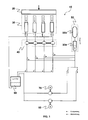
- Fig. 1 shows a schematic overview of a portion of the liquid streams within a particularly preferred designed lashing platform according to the invention.
- the lashing platform 10 has a lowerable receptacle 20 onto which a container can be placed, wherein the receptacle 20 can be lowered according to the weight of the container and the stroke of the arranged under the receptacle 20 pump cylinder 30.
- the pump cylinders 30 are preferably designed as a hydraulic pump cylinder and the lines of the lashing platform 10 as a hydraulic fluid hydraulic lines leading. In order to evenly lower a container placed on the lashing platform 10, it is advantageous to provide a compensation between differently loaded hydraulic cylinders 30 creating adjusting elements 40.
- the receptacle 20 or the pumping cylinders 30 are connected to the gas storage device 50 via preferably a plurality of first lines which ultimately open in a single line.
- the gas storage device 50 preferably consists of a gas reservoir 50b and a one-sided hydraulic fluid vorhaltenden piston accumulator 50a.
- the gas storage device 50 is - as known - connected via one or preferably a plurality of second lines with energized by the gas storage device 50 screwing 80 for removing and inserting twist locks from or into the container.
- a third line which is preferably designed as a hydraulic line, which is connected to the first line and / or the gas storage device 50.
- the third line is particularly preferably connected on its other side to a tank 60 for receiving hydraulic fluid, wherein in the tank 60 atmospheric pressure prevails and the hydraulic fluid collected there serves as a reservoir for the pump cylinder 30.
- the hydraulic fluid is completely supplied to the gas storage device 50 and the energy released when the container is placed on the lashing platform is stored completely in the gas storage device 50.
- the hydraulic cylinders 30 draw hydraulic fluid from the tank 60, so that the lashing platform 10 is ready for another settling operation.
- the stored energy in the gas storage device 50 can be supplied to the screw 80 at a later time via the second line, wherein the hydraulic fluid is returned to the reservoir of the tank 60.
- the volume flow conducted in the first line can be fed directly to the screw devices 80 via the second line.
- the volume flow conducted in the first line can be introduced into the third line and fed to the generator 70 or to the hydraulic motor connected to the generator. It is also conceivable that when the gas storage device 50 is full, one partial flow is supplied to the screw devices 80 and another partial flow is supplied to the generator.
- actuators e.g. Valves, acting control, which must have a corresponding sensor, provide.
- the entire volume flow can also be supplied directly to the tank 60, without the hydraulic fluid of the gas storage device 50, the screw 80 and the generator 70 is supplied. This may be required for maintenance, for example.
- a particularly simple regulation of the volume flows present in the three lines can be achieved in that a pressure valve, in particular a pressure-switching valve is provided that when exceeding a voltage applied to the gas storage device 50, the third linestructureschaltet and the excess, not to operate the screwing 80 supplies needed energy to the generator 70 for generating electrical energy.
- the energy generated by the generator 70 can be supplied to an accumulator and stored in this.
- the electrical energy is supplied to the electrical / electronic components of the lashing platform 10.
Description
Die Erfindung betrifft eine Laschplattform mit einer Aufnahme zum Lagern eines auf die Laschplattform abgesetzten Containers, wobei die Aufnahme in vertikaler Richtung federnd gelagert und über eine erste Leitung mit einer Gasspeichereinrichtung zum Speichern der bei Absetzen des Containers auf der Aufnahme der Laschplattform freiwerdenden Energie verbunden ist, und die Gasspeichereinrichtung über eine zweite Leitung mit von der Gasspeichereinrichtung energetisch gespeisten Schraubeinrichtungen zum Entnehmen und Einsetzen von Twist-Locks aus bzw. in den Container verbunden ist.The invention relates to a lashing platform with a receptacle for storing a container placed on the lashing platform, wherein the receptacle is mounted resiliently in the vertical direction and connected via a first line to a gas storage device for storing the energy released when the container is placed on the lashing platform. and the gas storage device is connected via a second line with energized by the gas storage means screwing devices for removing and inserting twist locks from or into the container.
Eine derartige Laschplattform ist beispielsweise aus der
Besonders vorteilhaft an dieser Anlage ist, dass die Schlitzgreifer zum Einsetzen und Entnehmen von Twist-Locks in bzw. aus den Sicherheits beschlägen der Container allein durch die bei Absetzen eines Containers auf der Laschplattform freiwerdenden Energie betrieben werden können.A particular advantage of this system is that the slot gripper for insertion and removal of twist locks in or out of the security fittings of the container can be operated solely by the released when discontinuing a container on the lashing platform energy.
Nachteilig ist jedoch, dass die elektrischen/elektronischen Komponenten, wie z.B. die Steuerung, die Sensorik und die Signalgebung der Laschplattform, entweder durch einen festen Stromanschluss oder über Akkumulatoren gespeist werden müssen, wobei ein fester Stromanschluss die freie Positionierung der ansonsten vorteilhaften Laschplattform einschränkt. Wenngleich die Akkumulatoren einfach ausgetauscht oder mittels an der Laschplattform installierter Plnotovoltaikanlagen einfach aufgeladen werden können, wäre es insbesondere an schattigen Standorten oder in Regionen mit lang andauernder Regenzeit wünschenswert, von sonnigem Wetter unabhängig zu sein.However, it is disadvantageous that the electrical / electronic components, such as e.g. the controller, the sensors and the signaling of the lashing platform, either by a fixed power supply or batteries must be powered, with a fixed power supply, the free positioning of the otherwise advantageous lashing platform limits. Although the rechargeable batteries can be easily replaced or easily recharged by plots installed on the lashing platform, it would be desirable to be independent of sunny weather, especially in shady locations or in regions with long lasting rainy season.
Aufgabe der Erfindung ist es daher, eine vollkommen von äußeren Energiequellen unabhängige Laschplattform zu schaffen.The object of the invention is therefore to provide a completely independent of external energy sources lashing platform.
Die Aufgabe wird durch die Vorrichtung mit den Merkmalen von Anspruch 1 gelöst. Die Unteransprüche geben vorteilhafte Ausgestaltungen der Erfindung wieder.The object is achieved by the device having the features of
Grundgedanke der Erfindung ist es, die beim Absetzen eines Containers auf der Laschplattform frei werdende Energie für den Fall, dass die Speicherkapazität der Gasspeichereinrichtung ausgeschöpft ist, d.h. der Gasspeicher "voll" ist, zur energetischen Versorgung der elektrischen/elektronischen Komponenten, insbesondere der Steuerung, zu verwenden.The basic idea of the invention is the energy released when a container is placed on the lashing platform in the event that the storage capacity of the gas storage device has been exhausted, ie. the gas storage is "full" to use for energetic supply of electrical / electronic components, in particular the controller.
Die Erfindung wird anhand eines in der einzigen
Die Aufnahme 20 bzw. die Pumpzylinder 30 sind über bevorzugt mehrere, schließlich in einer einzigen Leitung mündende erste Leitungen mit der Gasspeichereinrichtung 50 verbunden. Die Gasspeichereinrichtung 50 besteht bevorzugt aus einem Gasspeicher 50b und einem einseitig Hydraulikflüssigkeit vorhaltenden Kolbenspeicher 50a. Die Gasspeichereinrichtung 50 ist - wie bekannt - über eine oder bevorzugt mehrere zweite Leitungen mit von der Gasspeichereinrichtung 50 energetisch gespeisten Schraubeinrichtungen 80 zum Entnehmen und Einsetzen von Twist-Locks aus bzw. in den Container verbunden.The
Erfindungsgemäß ist nun eine bevorzugt als Hydraulikleitung ausgelegte dritte Leitung vorgesehen, die mit der ersten Leitung und/oder der Gasspeichereinrichtung 50 verbunden ist. Die dritte Leitung ist auf ihrer anderen Seite besonders bevorzugt mit einem Tank 60 zum Aufnehmen hydraulischer Flüssigkeit verbunden, wobei im Tank 60 Atmosphärendruck herrscht und die dort aufgefangene Hydraulikflüssigkeit als Reservoir für die Pumpzylinder 30 dient.According to the invention, a third line, which is preferably designed as a hydraulic line, is provided, which is connected to the first line and / or the
Aus dieser Anordnung ergeben sich nun unterschiedliche Möglichkeiten zur Nutzung der beim Absetzen von Containern mit unterschiedlichen Containergewichten freiwerdenden Energie durch Fördern von Hydraulikflüssigkeit durch die Pumpzylinder in unterschiedlicher Anzahl und Zusammensetzung in den Gasspeicher 50 bzw. den Tank 60.From this arrangement, there are now different possibilities for using the released energy when dispensing containers with different container weights by conveying hydraulic fluid through the pump cylinder in different numbers and composition in the
Soll Energie gespeichert werden und ist die Gasspeichereinrichtung 50 leer, wird die Hydraulikflüssigkeit vollständig der Gasspeichereinrichtung 50 zugeführt und die beim Absetzen des Containers auf die Laschplattform freiwerdende Energie wird vollständig in der Gasspeichereinrichtung 50 gespeichert. Beim Herunternehmen des Containers von der Laschplattform 10 saugen die Hydraulikzylinder 30 Hydraulikflüssigkeit aus dem Tank 60 an, sodass die Laschplattform 10 für einen weiteren Absetzvorgang bereit ist. Die in der Gasspeichereinrichtung 50 gespeicherte Energie kann zu einem späteren Zeitpunkt über die zweite Leitung den Schraubeinrichtungen 80 zugeführt werden, wobei die Hydraulikflüssigkeit in das Reservoir des Tanks 60 zurückgeführt wird.If energy is to be stored and the
Ist die Gasspeichereinrichtung 50 vollständig gefüllt, kann der in der ersten Leitung geführte Volumenstrom über die zweite Leitung den Schraubeinrichtungen 80 direkt zugeführt werden. Alternativ kann der in der ersten Leitung geführte Volumenstrom in die dritte Leitung eingeführt und dem Generator 70 bzw. dem mit dem Generator verbundenen Hydromotor zugeführt werden. Es ist auch denkbar, dass bei gefüllter Gasspeichereinrichtung 50 ein Teilstrom den Schraubeinrichtungen 80 und ein anderer Teilstrom dem Generator zugeführt wird.If the
Weiter ist denkbar, dass selbst wenn die Gasspeichereinrichtung 50 nicht vollständig gefüllt ist, ein nicht der Gasspeichereinrichtung 50 zugeführter Teilstrom den Schraubeinrichtungen 80 und/oder dieser oder ein weiterer Teilstrom dem Generator 70 zugeführt wird. Hierfür sind die zweite Leitung und die dritte Leitung bevorzugt parallel geschaltet.It is also conceivable that even if the
Zur Führung bzw. Regulierung der Teilströme ist eine auf entsprechende Stellglieder, z.B. Ventile, wirkende Steuerung, die über eine entsprechende Sensorik verfügen muss, vorzusehen.To guide or regulate the partial flows is a to corresponding actuators, e.g. Valves, acting control, which must have a corresponding sensor, provide.
Schließlich kann der gesamte Volumenstrom auch unmittelbar dem Tank 60 zugeführt werden, ohne dass Hydraulikflüssigkeit der Gasspeichereinrichtung 50, den Schraubeinrichtungen 80 und dem Generator 70 zugeführt wird. Dieses mag beispielsweise für Wartungsarbeiten erforderlich sein.Finally, the entire volume flow can also be supplied directly to the
Eine besonders einfache Regulierung der in den drei Leitungen vorliegenden Volumenströme kann dadurch erreicht werden, in dem ein Druckventil, insbesondere ein Druckzuschaltventil vorgesehen ist, dass bei Übersteigen eines an der Gasspeichereinrichtung 50 anliegenden Drucks die dritte Leitung hinzuschaltet und die überschüssige, nicht zum Betrieb der Schraubeinrichtungen 80 benötigte Energie dem Generator 70 zur Gewinnung elektrischer Energie zuführt.A particularly simple regulation of the volume flows present in the three lines can be achieved in that a pressure valve, in particular a pressure-switching valve is provided that when exceeding a voltage applied to the
Nach einem besonders vorteilhaften Ausführungsbeispiel kann die vom Generator 70 erzeugte Energie einem Akkumulator zugeführt und in diesem gespeichert werden. Die elektrische Energie wird den elektrischen / elektronischen Komponenten der Laschplattform 10 zugeführt.According to a particularly advantageous embodiment, the energy generated by the
Mit der vorliegenden Erfindung ist es möglich, eine energetisch vollständig unabhängig arbeitende Laschplattform bereitzustellen.With the present invention, it is possible to provide an energetically completely independent lashing platform.
Claims (10)
- A lashing platform (10) with a mount (20) for mounting a container set down on the lashing platform (10), wherein- the mount (10) is spring-mounted in the vertical direction and is connected via a first line to a gas storage means (50) for storing the energy released when setting the container down on the mount (20) of the lashing platform (10), and- the gas storage means (50) is connected via a second line to screwing devices which are supplied with energy from the gas storage means (50) and are intended for removing twist-locks from and inserting them into the container,characterized by
a third line connected to the first line and/or the gas storage means (50), and
a generator (40) for producing electrical energy that is driven by the volumetric flow conveyed in the third line. - The lashing platform (10) according to Claim 1, characterized by a control device that regulates the volume flow conveyed in the third line.
- The lashing platform (10) according to Claim 2, characterized in that the control device is a pressure valve.
- The lashing platform (10) according to one of the preceding claims, characterized in that the first and second lines are designed as lines conveying a hydraulic liquid.
- The lashing platform (10) according to one of the preceding claims, characterized in that the gas storage means (50) consists of a hydro store (50b) and a piston store (50a) storing a hydraulic liquid.
- The lashing platform (10) according to one of the preceding claims, characterized in that the third line is designed as a line conveying a hydraulic liquid and is connected to a tank (60) for receiving the hydraulic liquid.
- The lashing platform (10) according to one of the preceding claims, characterized in that the second and third lines are connected in parallel.
- The lashing platform (10) according to one of the preceding claims, characterized in that the generator (40) is arranged for supplying electrical energy to the electrical/electronic components of the lashing platform (10).
- The lashing platform (10) according to one of the preceding claims, characterized by an accumulator connected to the generator (40).
- The lashing platform (10) according Claim 9, characterized in that the accumulator is designed for supplying electrical energy to the lashing platform (10).
Priority Applications (1)
| Application Number | Priority Date | Filing Date | Title |
|---|---|---|---|
| PL11708684T PL2576397T3 (en) | 2010-05-28 | 2011-01-14 | Fully autonomous lashing platform |
Applications Claiming Priority (2)
| Application Number | Priority Date | Filing Date | Title |
|---|---|---|---|
| DE102010021822A DE102010021822B3 (en) | 2010-05-28 | 2010-05-28 | Completely autonomous lashing platform |
| PCT/DE2011/000029 WO2011147389A1 (en) | 2010-05-28 | 2011-01-14 | Fully autonomous lashing platform |
Publications (2)
| Publication Number | Publication Date |
|---|---|
| EP2576397A1 EP2576397A1 (en) | 2013-04-10 |
| EP2576397B1 true EP2576397B1 (en) | 2014-07-16 |
Family
ID=43828152
Family Applications (1)
| Application Number | Title | Priority Date | Filing Date |
|---|---|---|---|
| EP11708684.3A Active EP2576397B1 (en) | 2010-05-28 | 2011-01-14 | Fully autonomous lashing platform |
Country Status (13)
| Country | Link |
|---|---|
| US (1) | US9499336B2 (en) |
| EP (1) | EP2576397B1 (en) |
| CN (1) | CN102858656B (en) |
| AU (1) | AU2011257643B2 (en) |
| DE (1) | DE102010021822B3 (en) |
| DK (1) | DK2576397T3 (en) |
| ES (1) | ES2512865T3 (en) |
| HK (1) | HK1177615A1 (en) |
| NZ (1) | NZ601671A (en) |
| PL (1) | PL2576397T3 (en) |
| PT (1) | PT2576397E (en) |
| SG (1) | SG183373A1 (en) |
| WO (1) | WO2011147389A1 (en) |
Families Citing this family (1)
| Publication number | Priority date | Publication date | Assignee | Title |
|---|---|---|---|---|
| DE102009020999A1 (en) * | 2009-05-12 | 2010-11-18 | Hydac System Gmbh | lashing platform |
Family Cites Families (12)
| Publication number | Priority date | Publication date | Assignee | Title |
|---|---|---|---|---|
| DE3666020D1 (en) * | 1985-08-13 | 1989-11-09 | Martin Werder | Cross-country vehicle |
| DE3602510A1 (en) * | 1986-01-28 | 1987-07-30 | Steinbock Gmbh | HYDRAULIC LIFTING |
| US4983094A (en) * | 1986-07-18 | 1991-01-08 | Caterpillar Industrial Inc. | Load lifting attachment |
| DE10023436A1 (en) * | 2000-05-12 | 2001-11-15 | Tax Technical Consultancy Gmbh | Operating method for container-handling system involves transmitting release signal from release signal generator on spreader to release signal receiver near each intermediate coupling unit |
| JP2002145572A (en) * | 2000-11-08 | 2002-05-22 | Tcm Corp | Spreader device |
| AU2005335498A1 (en) * | 2005-08-16 | 2007-02-22 | Sunrose Tecdesign Pte Ltd. | Inter-box connector (IBC) storage and handling system |
| DE102005052108A1 (en) * | 2005-11-02 | 2007-05-03 | Hydac Technology Gmbh | Hydraulic system for lifting and lowering loads with stacks, has fed energy which can be recalled from support of displacement movement during drive direction moving in opposite directions from storage device |
| DE102006015807A1 (en) | 2006-03-02 | 2007-09-06 | Rainer Kapelski | Device and method for inserting and removing twist-lock container securing fittings |
| DE202006003435U1 (en) * | 2006-03-02 | 2006-04-27 | Kapelski, Rainer | Assembly to insert container twist-lock by twist-lock fittings remotely operated by hydraulic or pneumatic power |
| EP2280841A2 (en) * | 2008-04-09 | 2011-02-09 | Sustainx, Inc. | Systems and methods for energy storage and recovery using compressed gas |
| US8061951B2 (en) * | 2008-04-09 | 2011-11-22 | Wcdi, Llc | Apparatus for tipping intermodal containers |
| DE102009020999A1 (en) * | 2009-05-12 | 2010-11-18 | Hydac System Gmbh | lashing platform |
-
2010
- 2010-05-28 DE DE102010021822A patent/DE102010021822B3/en not_active Expired - Fee Related
-
2011
- 2011-01-14 WO PCT/DE2011/000029 patent/WO2011147389A1/en active Application Filing
- 2011-01-14 CN CN201180020262.9A patent/CN102858656B/en not_active Expired - Fee Related
- 2011-01-14 PT PT117086843T patent/PT2576397E/en unknown
- 2011-01-14 US US13/635,282 patent/US9499336B2/en active Active
- 2011-01-14 NZ NZ601671A patent/NZ601671A/en not_active IP Right Cessation
- 2011-01-14 DK DK11708684.3T patent/DK2576397T3/en active
- 2011-01-14 AU AU2011257643A patent/AU2011257643B2/en active Active
- 2011-01-14 PL PL11708684T patent/PL2576397T3/en unknown
- 2011-01-14 EP EP11708684.3A patent/EP2576397B1/en active Active
- 2011-01-14 ES ES11708684.3T patent/ES2512865T3/en active Active
- 2011-01-14 SG SG2012061065A patent/SG183373A1/en unknown
-
2013
- 2013-05-08 HK HK13105525.8A patent/HK1177615A1/en not_active IP Right Cessation
Also Published As
| Publication number | Publication date |
|---|---|
| CN102858656B (en) | 2014-04-16 |
| EP2576397A1 (en) | 2013-04-10 |
| PT2576397E (en) | 2014-09-16 |
| DK2576397T3 (en) | 2014-08-04 |
| AU2011257643A1 (en) | 2012-08-23 |
| NZ601671A (en) | 2013-08-30 |
| DE102010021822B3 (en) | 2011-07-21 |
| HK1177615A1 (en) | 2013-08-23 |
| WO2011147389A1 (en) | 2011-12-01 |
| ES2512865T3 (en) | 2014-10-24 |
| CN102858656A (en) | 2013-01-02 |
| AU2011257643B2 (en) | 2015-09-10 |
| SG183373A1 (en) | 2012-09-27 |
| PL2576397T3 (en) | 2014-10-31 |
| US9499336B2 (en) | 2016-11-22 |
| US20130056093A1 (en) | 2013-03-07 |
Similar Documents
| Publication | Publication Date | Title |
|---|---|---|
| WO2017137100A1 (en) | System and method for storing water and supplying water to an internal combustion engine of a motor vehicle | |
| EP3184807B1 (en) | System for energy storage and recovery | |
| EP3482440A1 (en) | Cavern battery bank | |
| DE102008028764A1 (en) | Mechanical Hubspeicher power plant with Seilwindenhub | |
| EP3049667A1 (en) | Method and system for combined pump water pressure-compressed air energy storage at constant turbine water pressure | |
| DE102013018741A1 (en) | Device unit and method for energy storage and recovery | |
| EP2576397B1 (en) | Fully autonomous lashing platform | |
| WO2017102059A1 (en) | Filling station having a constant-pressure store | |
| DE202008016607U1 (en) | Pumpless water supply device for mobile use | |
| EP1355371B1 (en) | Adapter as alternative for a fuel cartridge | |
| EP3914822A1 (en) | Method and device for storing energy | |
| WO2012019778A2 (en) | Method and system for storing and, as needed, discharging electrical energy | |
| EP3026271B1 (en) | Movement compensation device | |
| WO2015024678A1 (en) | Drive system for a water vehicle, method for operating a drive system, and water vehicle having a drive system | |
| DE102008050389A1 (en) | Method for energy storage in extensive power network, involves releasing stored energy from power network driver up to predetermined limit for covering consumption peaks of individual energy storages | |
| DE102020112724A1 (en) | Energy storage and recovery system | |
| DE102009043356A1 (en) | Device for utilizing lift energy of lifting bodies for driving alternating current generator, has lifting bodies fastened to rotatably supported transport device and filled with liquid and gas at pressure | |
| DE202011104280U1 (en) | Oil change vehicle, in particular for wind turbines | |
| WO1990005797A1 (en) | Installation for etching objects | |
| DE202017005622U1 (en) | Gravity buoyancy unit | |
| DE102004005396B4 (en) | Pressure reducing device | |
| DE1503276C3 (en) | Propulsion system with liquid turbine | |
| DE4104033A1 (en) | Solar cell driven garden pump - has current supply controlled by storage and control electronics for operation of immersion pump | |
| DE246292C (en) | ||
| DE202020106761U1 (en) | Hydraulic-pneumatic energy storage and generation system |
Legal Events
| Date | Code | Title | Description |
|---|---|---|---|
| PUAI | Public reference made under article 153(3) epc to a published international application that has entered the european phase |
Free format text: ORIGINAL CODE: 0009012 |
|
| 17P | Request for examination filed |
Effective date: 20120613 |
|
| AK | Designated contracting states |
Kind code of ref document: A1 Designated state(s): AL AT BE BG CH CY CZ DE DK EE ES FI FR GB GR HR HU IE IS IT LI LT LU LV MC MK MT NL NO PL PT RO RS SE SI SK SM TR |
|
| DAX | Request for extension of the european patent (deleted) | ||
| RAP1 | Party data changed (applicant data changed or rights of an application transferred) |
Owner name: KALP GMBH |
|
| RIN1 | Information on inventor provided before grant (corrected) |
Inventor name: KAPELSKI, RAINER |
|
| GRAP | Despatch of communication of intention to grant a patent |
Free format text: ORIGINAL CODE: EPIDOSNIGR1 |
|
| INTG | Intention to grant announced |
Effective date: 20140417 |
|
| GRAS | Grant fee paid |
Free format text: ORIGINAL CODE: EPIDOSNIGR3 |
|
| GRAA | (expected) grant |
Free format text: ORIGINAL CODE: 0009210 |
|
| AK | Designated contracting states |
Kind code of ref document: B1 Designated state(s): AL AT BE BG CH CY CZ DE DK EE ES FI FR GB GR HR HU IE IS IT LI LT LU LV MC MK MT NL NO PL PT RO RS SE SI SK SM TR |
|
| REG | Reference to a national code |
Ref country code: GB Ref legal event code: FG4D Free format text: NOT ENGLISH |
|
| REG | Reference to a national code |
Ref country code: CH Ref legal event code: EP |
|
| REG | Reference to a national code |
Ref country code: DK Ref legal event code: T3 Effective date: 20140801 |
|
| REG | Reference to a national code |
Ref country code: IE Ref legal event code: FG4D Free format text: LANGUAGE OF EP DOCUMENT: GERMAN |
|
| REG | Reference to a national code |
Ref country code: AT Ref legal event code: REF Ref document number: 677472 Country of ref document: AT Kind code of ref document: T Effective date: 20140815 |
|
| REG | Reference to a national code |
Ref country code: DE Ref legal event code: R096 Ref document number: 502011003748 Country of ref document: DE Effective date: 20140828 |
|
| REG | Reference to a national code |
Ref country code: PT Ref legal event code: SC4A Free format text: AVAILABILITY OF NATIONAL TRANSLATION Effective date: 20140909 |
|
| REG | Reference to a national code |
Ref country code: SE Ref legal event code: TRGR |
|
| REG | Reference to a national code |
Ref country code: NL Ref legal event code: T3 |
|
| REG | Reference to a national code |
Ref country code: ES Ref legal event code: FG2A Ref document number: 2512865 Country of ref document: ES Kind code of ref document: T3 Effective date: 20141024 |
|
| REG | Reference to a national code |
Ref country code: PL Ref legal event code: T3 |
|
| REG | Reference to a national code |
Ref country code: LT Ref legal event code: MG4D |
|
| PG25 | Lapsed in a contracting state [announced via postgrant information from national office to epo] |
Ref country code: LT Free format text: LAPSE BECAUSE OF FAILURE TO SUBMIT A TRANSLATION OF THE DESCRIPTION OR TO PAY THE FEE WITHIN THE PRESCRIBED TIME-LIMIT Effective date: 20140716 Ref country code: BG Free format text: LAPSE BECAUSE OF FAILURE TO SUBMIT A TRANSLATION OF THE DESCRIPTION OR TO PAY THE FEE WITHIN THE PRESCRIBED TIME-LIMIT Effective date: 20141016 Ref country code: GR Free format text: LAPSE BECAUSE OF FAILURE TO SUBMIT A TRANSLATION OF THE DESCRIPTION OR TO PAY THE FEE WITHIN THE PRESCRIBED TIME-LIMIT Effective date: 20141017 Ref country code: NO Free format text: LAPSE BECAUSE OF FAILURE TO SUBMIT A TRANSLATION OF THE DESCRIPTION OR TO PAY THE FEE WITHIN THE PRESCRIBED TIME-LIMIT Effective date: 20141016 |
|
| PG25 | Lapsed in a contracting state [announced via postgrant information from national office to epo] |
Ref country code: RS Free format text: LAPSE BECAUSE OF FAILURE TO SUBMIT A TRANSLATION OF THE DESCRIPTION OR TO PAY THE FEE WITHIN THE PRESCRIBED TIME-LIMIT Effective date: 20140716 Ref country code: IS Free format text: LAPSE BECAUSE OF FAILURE TO SUBMIT A TRANSLATION OF THE DESCRIPTION OR TO PAY THE FEE WITHIN THE PRESCRIBED TIME-LIMIT Effective date: 20141116 Ref country code: LV Free format text: LAPSE BECAUSE OF FAILURE TO SUBMIT A TRANSLATION OF THE DESCRIPTION OR TO PAY THE FEE WITHIN THE PRESCRIBED TIME-LIMIT Effective date: 20140716 Ref country code: CY Free format text: LAPSE BECAUSE OF FAILURE TO SUBMIT A TRANSLATION OF THE DESCRIPTION OR TO PAY THE FEE WITHIN THE PRESCRIBED TIME-LIMIT Effective date: 20140716 |
|
| REG | Reference to a national code |
Ref country code: DE Ref legal event code: R097 Ref document number: 502011003748 Country of ref document: DE |
|
| PG25 | Lapsed in a contracting state [announced via postgrant information from national office to epo] |
Ref country code: RO Free format text: LAPSE BECAUSE OF FAILURE TO SUBMIT A TRANSLATION OF THE DESCRIPTION OR TO PAY THE FEE WITHIN THE PRESCRIBED TIME-LIMIT Effective date: 20140716 Ref country code: SK Free format text: LAPSE BECAUSE OF FAILURE TO SUBMIT A TRANSLATION OF THE DESCRIPTION OR TO PAY THE FEE WITHIN THE PRESCRIBED TIME-LIMIT Effective date: 20140716 Ref country code: CZ Free format text: LAPSE BECAUSE OF FAILURE TO SUBMIT A TRANSLATION OF THE DESCRIPTION OR TO PAY THE FEE WITHIN THE PRESCRIBED TIME-LIMIT Effective date: 20140716 Ref country code: EE Free format text: LAPSE BECAUSE OF FAILURE TO SUBMIT A TRANSLATION OF THE DESCRIPTION OR TO PAY THE FEE WITHIN THE PRESCRIBED TIME-LIMIT Effective date: 20140716 |
|
| PLBE | No opposition filed within time limit |
Free format text: ORIGINAL CODE: 0009261 |
|
| STAA | Information on the status of an ep patent application or granted ep patent |
Free format text: STATUS: NO OPPOSITION FILED WITHIN TIME LIMIT |
|
| 26N | No opposition filed |
Effective date: 20150417 |
|
| REG | Reference to a national code |
Ref country code: CH Ref legal event code: PL |
|
| PG25 | Lapsed in a contracting state [announced via postgrant information from national office to epo] |
Ref country code: LU Free format text: LAPSE BECAUSE OF FAILURE TO SUBMIT A TRANSLATION OF THE DESCRIPTION OR TO PAY THE FEE WITHIN THE PRESCRIBED TIME-LIMIT Effective date: 20150114 |
|
| PG25 | Lapsed in a contracting state [announced via postgrant information from national office to epo] |
Ref country code: MC Free format text: LAPSE BECAUSE OF FAILURE TO SUBMIT A TRANSLATION OF THE DESCRIPTION OR TO PAY THE FEE WITHIN THE PRESCRIBED TIME-LIMIT Effective date: 20140716 |
|
| PG25 | Lapsed in a contracting state [announced via postgrant information from national office to epo] |
Ref country code: LI Free format text: LAPSE BECAUSE OF NON-PAYMENT OF DUE FEES Effective date: 20150131 Ref country code: CH Free format text: LAPSE BECAUSE OF NON-PAYMENT OF DUE FEES Effective date: 20150131 |
|
| PG25 | Lapsed in a contracting state [announced via postgrant information from national office to epo] |
Ref country code: SI Free format text: LAPSE BECAUSE OF FAILURE TO SUBMIT A TRANSLATION OF THE DESCRIPTION OR TO PAY THE FEE WITHIN THE PRESCRIBED TIME-LIMIT Effective date: 20140716 |
|
| REG | Reference to a national code |
Ref country code: FR Ref legal event code: PLFP Year of fee payment: 6 |
|
| PG25 | Lapsed in a contracting state [announced via postgrant information from national office to epo] |
Ref country code: MT Free format text: LAPSE BECAUSE OF FAILURE TO SUBMIT A TRANSLATION OF THE DESCRIPTION OR TO PAY THE FEE WITHIN THE PRESCRIBED TIME-LIMIT Effective date: 20140716 |
|
| REG | Reference to a national code |
Ref country code: FR Ref legal event code: PLFP Year of fee payment: 7 |
|
| REG | Reference to a national code |
Ref country code: AT Ref legal event code: MM01 Ref document number: 677472 Country of ref document: AT Kind code of ref document: T Effective date: 20160114 |
|
| PG25 | Lapsed in a contracting state [announced via postgrant information from national office to epo] |
Ref country code: AT Free format text: LAPSE BECAUSE OF NON-PAYMENT OF DUE FEES Effective date: 20160114 Ref country code: HU Free format text: LAPSE BECAUSE OF FAILURE TO SUBMIT A TRANSLATION OF THE DESCRIPTION OR TO PAY THE FEE WITHIN THE PRESCRIBED TIME-LIMIT; INVALID AB INITIO Effective date: 20110114 Ref country code: SM Free format text: LAPSE BECAUSE OF FAILURE TO SUBMIT A TRANSLATION OF THE DESCRIPTION OR TO PAY THE FEE WITHIN THE PRESCRIBED TIME-LIMIT Effective date: 20140716 |
|
| PG25 | Lapsed in a contracting state [announced via postgrant information from national office to epo] |
Ref country code: HR Free format text: LAPSE BECAUSE OF FAILURE TO SUBMIT A TRANSLATION OF THE DESCRIPTION OR TO PAY THE FEE WITHIN THE PRESCRIBED TIME-LIMIT Effective date: 20140716 |
|
| PG25 | Lapsed in a contracting state [announced via postgrant information from national office to epo] |
Ref country code: TR Free format text: LAPSE BECAUSE OF FAILURE TO SUBMIT A TRANSLATION OF THE DESCRIPTION OR TO PAY THE FEE WITHIN THE PRESCRIBED TIME-LIMIT Effective date: 20140716 |
|
| REG | Reference to a national code |
Ref country code: FR Ref legal event code: PLFP Year of fee payment: 8 |
|
| PG25 | Lapsed in a contracting state [announced via postgrant information from national office to epo] |
Ref country code: MK Free format text: LAPSE BECAUSE OF FAILURE TO SUBMIT A TRANSLATION OF THE DESCRIPTION OR TO PAY THE FEE WITHIN THE PRESCRIBED TIME-LIMIT Effective date: 20140716 |
|
| PG25 | Lapsed in a contracting state [announced via postgrant information from national office to epo] |
Ref country code: AL Free format text: LAPSE BECAUSE OF FAILURE TO SUBMIT A TRANSLATION OF THE DESCRIPTION OR TO PAY THE FEE WITHIN THE PRESCRIBED TIME-LIMIT Effective date: 20140716 |
|
| REG | Reference to a national code |
Ref country code: DE Ref legal event code: R082 Ref document number: 502011003748 Country of ref document: DE Representative=s name: LOBEMEIER, MARTIN LANDOLF, DR., DE |
|
| PGFP | Annual fee paid to national office [announced via postgrant information from national office to epo] |
Ref country code: PL Payment date: 20181217 Year of fee payment: 9 Ref country code: PT Payment date: 20181218 Year of fee payment: 9 |
|
| PGFP | Annual fee paid to national office [announced via postgrant information from national office to epo] |
Ref country code: IE Payment date: 20190123 Year of fee payment: 10 |
|
| PGFP | Annual fee paid to national office [announced via postgrant information from national office to epo] |
Ref country code: DK Payment date: 20190123 Year of fee payment: 9 |
|
| REG | Reference to a national code |
Ref country code: DK Ref legal event code: EBP Effective date: 20200131 |
|
| REG | Reference to a national code |
Ref country code: SE Ref legal event code: EUG |
|
| REG | Reference to a national code |
Ref country code: SE Ref legal event code: EUG |
|
| PG25 | Lapsed in a contracting state [announced via postgrant information from national office to epo] |
Ref country code: SE Free format text: LAPSE BECAUSE OF NON-PAYMENT OF DUE FEES Effective date: 20200115 Ref country code: PT Free format text: LAPSE BECAUSE OF NON-PAYMENT OF DUE FEES Effective date: 20200814 |
|
| PG25 | Lapsed in a contracting state [announced via postgrant information from national office to epo] |
Ref country code: IE Free format text: LAPSE BECAUSE OF NON-PAYMENT OF DUE FEES Effective date: 20200114 Ref country code: DK Free format text: LAPSE BECAUSE OF NON-PAYMENT OF DUE FEES Effective date: 20200131 Ref country code: IT Free format text: LAPSE BECAUSE OF NON-PAYMENT OF DUE FEES Effective date: 20200114 |
|
| PGFP | Annual fee paid to national office [announced via postgrant information from national office to epo] |
Ref country code: SE Payment date: 20210721 Year of fee payment: 11 |
|
| PG25 | Lapsed in a contracting state [announced via postgrant information from national office to epo] |
Ref country code: PL Free format text: LAPSE BECAUSE OF NON-PAYMENT OF DUE FEES Effective date: 20200114 |
|
| PGFP | Annual fee paid to national office [announced via postgrant information from national office to epo] |
Ref country code: FR Payment date: 20230124 Year of fee payment: 13 Ref country code: FI Payment date: 20230120 Year of fee payment: 13 Ref country code: ES Payment date: 20230330 Year of fee payment: 13 |
|
| PGFP | Annual fee paid to national office [announced via postgrant information from national office to epo] |
Ref country code: GB Payment date: 20230119 Year of fee payment: 13 Ref country code: DE Payment date: 20230123 Year of fee payment: 13 Ref country code: BE Payment date: 20230119 Year of fee payment: 13 |
|
| PGFP | Annual fee paid to national office [announced via postgrant information from national office to epo] |
Ref country code: NL Payment date: 20230119 Year of fee payment: 13 |