EP2576331B1 - Système marin de levage et de descente de charges - Google Patents
Système marin de levage et de descente de charges Download PDFInfo
- Publication number
- EP2576331B1 EP2576331B1 EP11722594.6A EP11722594A EP2576331B1 EP 2576331 B1 EP2576331 B1 EP 2576331B1 EP 11722594 A EP11722594 A EP 11722594A EP 2576331 B1 EP2576331 B1 EP 2576331B1
- Authority
- EP
- European Patent Office
- Prior art keywords
- cable
- winch
- lowering
- engaging members
- raising
- Prior art date
- Legal status (The legal status is an assumption and is not a legal conclusion. Google has not performed a legal analysis and makes no representation as to the accuracy of the status listed.)
- Active
Links
Images


Classifications
-
- F—MECHANICAL ENGINEERING; LIGHTING; HEATING; WEAPONS; BLASTING
- F16—ENGINEERING ELEMENTS AND UNITS; GENERAL MEASURES FOR PRODUCING AND MAINTAINING EFFECTIVE FUNCTIONING OF MACHINES OR INSTALLATIONS; THERMAL INSULATION IN GENERAL
- F16L—PIPES; JOINTS OR FITTINGS FOR PIPES; SUPPORTS FOR PIPES, CABLES OR PROTECTIVE TUBING; MEANS FOR THERMAL INSULATION IN GENERAL
- F16L1/00—Laying or reclaiming pipes; Repairing or joining pipes on or under water
- F16L1/12—Laying or reclaiming pipes on or under water
- F16L1/20—Accessories therefor, e.g. floats, weights
- F16L1/202—Accessories therefor, e.g. floats, weights fixed on or to vessels
- F16L1/207—Pipe handling apparatus
-
- B—PERFORMING OPERATIONS; TRANSPORTING
- B63—SHIPS OR OTHER WATERBORNE VESSELS; RELATED EQUIPMENT
- B63B—SHIPS OR OTHER WATERBORNE VESSELS; EQUIPMENT FOR SHIPPING
- B63B27/00—Arrangement of ship-based loading or unloading equipment for cargo or passengers
- B63B27/08—Arrangement of ship-based loading or unloading equipment for cargo or passengers of winches
-
- B—PERFORMING OPERATIONS; TRANSPORTING
- B63—SHIPS OR OTHER WATERBORNE VESSELS; RELATED EQUIPMENT
- B63C—LAUNCHING, HAULING-OUT, OR DRY-DOCKING OF VESSELS; LIFE-SAVING IN WATER; EQUIPMENT FOR DWELLING OR WORKING UNDER WATER; MEANS FOR SALVAGING OR SEARCHING FOR UNDERWATER OBJECTS
- B63C7/00—Salvaging of disabled, stranded, or sunken vessels; Salvaging of vessel parts or furnishings, e.g. of safes; Salvaging of other underwater objects
- B63C7/02—Salvaging of disabled, stranded, or sunken vessels; Salvaging of vessel parts or furnishings, e.g. of safes; Salvaging of other underwater objects in which the lifting is done by hauling
-
- B—PERFORMING OPERATIONS; TRANSPORTING
- B66—HOISTING; LIFTING; HAULING
- B66C—CRANES; LOAD-ENGAGING ELEMENTS OR DEVICES FOR CRANES, CAPSTANS, WINCHES, OR TACKLES
- B66C13/00—Other constructional features or details
- B66C13/18—Control systems or devices
-
- B—PERFORMING OPERATIONS; TRANSPORTING
- B66—HOISTING; LIFTING; HAULING
- B66C—CRANES; LOAD-ENGAGING ELEMENTS OR DEVICES FOR CRANES, CAPSTANS, WINCHES, OR TACKLES
- B66C23/00—Cranes comprising essentially a beam, boom, or triangular structure acting as a cantilever and mounted for translatory of swinging movements in vertical or horizontal planes or a combination of such movements, e.g. jib-cranes, derricks, tower cranes
- B66C23/18—Cranes comprising essentially a beam, boom, or triangular structure acting as a cantilever and mounted for translatory of swinging movements in vertical or horizontal planes or a combination of such movements, e.g. jib-cranes, derricks, tower cranes specially adapted for use in particular purposes
- B66C23/36—Cranes comprising essentially a beam, boom, or triangular structure acting as a cantilever and mounted for translatory of swinging movements in vertical or horizontal planes or a combination of such movements, e.g. jib-cranes, derricks, tower cranes specially adapted for use in particular purposes mounted on road or rail vehicles; Manually-movable jib-cranes for use in workshops; Floating cranes
- B66C23/52—Floating cranes
-
- B—PERFORMING OPERATIONS; TRANSPORTING
- B66—HOISTING; LIFTING; HAULING
- B66D—CAPSTANS; WINCHES; TACKLES, e.g. PULLEY BLOCKS; HOISTS
- B66D1/00—Rope, cable, or chain winding mechanisms; Capstans
- B66D1/26—Rope, cable, or chain winding mechanisms; Capstans having several drums or barrels
-
- B—PERFORMING OPERATIONS; TRANSPORTING
- B66—HOISTING; LIFTING; HAULING
- B66D—CAPSTANS; WINCHES; TACKLES, e.g. PULLEY BLOCKS; HOISTS
- B66D1/00—Rope, cable, or chain winding mechanisms; Capstans
- B66D1/54—Safety gear
- B66D1/58—Safety gear responsive to excess of load
-
- F—MECHANICAL ENGINEERING; LIGHTING; HEATING; WEAPONS; BLASTING
- F16—ENGINEERING ELEMENTS AND UNITS; GENERAL MEASURES FOR PRODUCING AND MAINTAINING EFFECTIVE FUNCTIONING OF MACHINES OR INSTALLATIONS; THERMAL INSULATION IN GENERAL
- F16L—PIPES; JOINTS OR FITTINGS FOR PIPES; SUPPORTS FOR PIPES, CABLES OR PROTECTIVE TUBING; MEANS FOR THERMAL INSULATION IN GENERAL
- F16L1/00—Laying or reclaiming pipes; Repairing or joining pipes on or under water
- F16L1/12—Laying or reclaiming pipes on or under water
-
- B—PERFORMING OPERATIONS; TRANSPORTING
- B66—HOISTING; LIFTING; HAULING
- B66C—CRANES; LOAD-ENGAGING ELEMENTS OR DEVICES FOR CRANES, CAPSTANS, WINCHES, OR TACKLES
- B66C13/00—Other constructional features or details
- B66C13/04—Auxiliary devices for controlling movements of suspended loads, or preventing cable slack
- B66C13/06—Auxiliary devices for controlling movements of suspended loads, or preventing cable slack for minimising or preventing longitudinal or transverse swinging of loads
Definitions
- the invention relates to a marine load raising and lowering system for use on a vessel, preferably a vessel for laying an offshore pipeline.
- Such a system is well known, for example on vessels used for laying pipelines.
- the system is then used in particular for abandoning and recovering a pipeline, to which system and method are referred to as an A&R system and an A&R method.
- A&R system system and method
- A&R method A&R method
- such A&R method is carried out by connecting an A&R head to the end of the laid pipeline; connecting a cable to this head; transferring pipeline tension from a pipeline tensioning arrangement on the vessel that is used during pipelaying to a winch via the cable; and laying the pipeline and the head on the bottom of the sea by controlled lowering of the cable via driving means of the winch.
- a marine load raising and lowering system may also be used to place other components on the bottom of the sea, e.g. a canister.
- US 7,182,550 discloses an A&R system and method using a single winch, cable and associated driving means for lowering and raising the laid pipeline.
- the use of this system in deep water, e.g. several hundred metres or even more than one kilometre causes several problems.
- the cable associated with the winch must have a very high tensile strength to support a heavy load. This requirement leads to a heavy cable with the result that the weight of the cable itself becomes a further factor. Thus an even higher load capacity of the winch will be required.
- first winch comprising first driving means for raising or lowering a first cable portion and a second winch comprising second driving means for raising or lowering a second cable portion
- Operating means are provided which are connected to the first and second driving means of the first and second winch for synchronising the driving means so as to perform synchronous raising and lowering of the first and second cable portions.
- the first cable portion and the second cable portion are interconnected at the lower ends via a rotatable equalizing sheave. This sheave will rotate when the operation of the first and second cable portions is not fully synchronous, thereby preventing overload of the cable portions when only a small deviation of synchronicity occurs.
- the load connector to which the load is or can be attached, is connected to the axle of the equalizing sheave.
- a disadvantage of the system according to WO 2009/002142 is that especially for deep water purposes the load connector may rotate about a vertical oriented axis, thereby entangling the two cable portions. As the first and second cable can move relative to each other due to rotation of the equalizing sheave, the entangled cable portions may graze each other which leads to increased wear resulting in reduced lifetime and possibly breakage of the cable portions.
- a marine load raising and lowering system for use on a vessel, preferably a vessel for laying an offshore pipeline, which system comprises:
- An advantage of the first-tension equalizing mechanism is that the relative movement of the cable portions between the first tension equalizing mechanism and the load connector (where the entanglement will take place) is decreased, thereby reducing wear of the two cables.
- Another advantage may be that the load connector is supported by at least two cables instead of one cable, thereby resulting in a more redundant system.
- connection of the cables to the load connector requires less space then in case of a relatively large equalizing sheave, so that the load connector is able to pass smaller openings, e.g. such as openings in tensioners, or moonpools.
- the first cable-engaging members comprise a first sheave to engage with the first cable and a second sheave to engage with the second cable. As the first and second sheaves are able to rotate thereby moving along with the respective first and second cable, wear between the first cable-engaging members and the first and second cable is minimized.
- rotation axes of the first and second sheave may be aligned on a common axis.
- the system comprises one or more sheaves upstream and/or downstream of the first tension equalizing system to guide the first and second cable from and to the first cable-engaging members.
- the sheaves are preferably fixed to the vessel.
- the sheaves ensure minimal wear of the cables when passing the sheaves due to their rotation possibilities.
- Another advantage of the sheaves may be that they direct a portion of the respective cables in another direction than the main portion of the cables which will have a substantially vertical orientation when not wound on the winches. Movement of the first cable-engaging members then hauls in one cable and pays out the other cable thereby allowing to equalize the tensions in said cables.
- cables, and especially long cables for deepwater purposes will also have a spring-like behaviour, equalizing the tension will only cause movement of the cables in a top portion near the first tension equalizing mechanism and minimal movement at a bottom portion near the load connector. Hence decreasing the wear of the cables due to this movement.
- a heave compensator is provided to haul in or pay out both cables at the same time to compensate for the undesired vessel motions and protect the cables from an overload.
- the heave compensator is provided on the first and second winch.
- the heave compensator may be provided between the first and second winch and the tension equalizing mechanism.
- the heave compensator may also be integrated in the tension equalizing mechanism, for instance by providing a cylinder between the first cable-engaging members.
- the heave compensator is provided for one of the first or second cable only.
- the heave compensator cooperates with the tension equalizing mechanism.
- the heave compensator will haul in or pay out one of the first or second cable due to vessel motions, and the tension equalizing mechanism will ensure that the other of the first or second cable is paid out or hauled in as well.
- the working range of the tension equalizing mechanism must be large enough or the winches should be controlled properly based on movement of the tension equalizing mechanism in order to limit said movement of the tension equalizing mechanism. Movement of the tension equalizing mechanism can be measured using a displacement sensor.
- each of the first and second winch is a traction winch cooperating with a respective storage winch driven by associated operating means which are configured to provide a hold-back force in the first and second cable for the respective traction winch.
- a hold-back force sensor is provided in contact with the operating means of the storage winches in order to synchronize movement of the storage winches with the respective first and second winch.
- a displacement sensor in contact with the operating means is provided measuring the displacement of the first cable-engaging members to correct for non-synchronous raising or lowering of the first and second cable. This makes it possible to keep the first cable-engaging members within a predetermined displacement range and thus may reduce the size of the first tension equalizing mechanism.
- the first reference structure is fixed relative to the vessel.
- the first reference structure can also be moveable, e.g. when it is part of or connected to a heave compensator.
- the system comprises:
- first and second reference structures of the first and second tension equalizing mechanism are preferably moveable relative to the vessel.
- the third reference structure is preferably fixed to the vessel.
- the first and/or second cable-engaging members are preferably interconnected using a beam or a connecting cable.
- the corresponding reference structure may be a sheave across which the connecting cable is run.
- the corresponding reference structures are preferably interconnected using a beam or a connecting cable similar to the interconnection of the first and second cable-engaging members.
- the load raising and lowering system operates as an abandonment and recovery system.
- the invention also relates to a method for lowering a load from a vessel, preferably a vessel for laying an offshore pipeline, wherein use is made of a load raising and lowering system comprising first and second winches with respective first and second driving means for raising or lowering first and second cables from the winches, operating means connected to the first and second driving means of the first and second winch for synchronising the driving means so as to perform synchronous raising or lowering of the cables, and a first tension equalizing mechanism for equalizing tensions in the first and second cable, said first tension equalizing mechanism having interconnected first cable-engaging members to engage with the first and second cable, wherein said first cable-engaging members are moveable relative to a first reference structure to be mounted on the vessel, and wherein the first tension equalizing mechanism is configured to move the first cable-engaging members under the effect of a difference in tension in the first and second cable so as to equalize said tensions, said method comprising the following steps:
- the method also includes the following steps:
- the signals provided to the driving means by the operating means are adjusted such that the displacement of the first cable-engaging members is limited to a predetermined displacement range.
- Cables mentioned in this application may each have a length of at least 500m, preferably at least 1000m, more preferably at least 2000m, and most preferably at least 3000m.
- the maximum capacity of the marine load raising and lowering system may be at least 200 metric tons, preferably at least 400 metric tons, more preferably at least 600 metric tons, and most preferably at least 800 metric tons.
- Figure 1 depicts a marine load raising and lowering system 1 for use on a vessel, preferably a vessel for laying an offshore pipeline, which system comprises a first winch 2 with first driving means 3 for raising and lowering a first cable 4 from the first winch 2, and a second winch 5 with second driving means 6 for raising and lowering a second cable 7 from the second winch 5.
- the first and second driving means 3, 6 can be synchronized by operating means 8 connected to the first and second driving means so as to perform synchronous raising and lowering of the first and second cable.
- the operating means are in this embodiment electronic operating means.
- the first and second cable 4,7 will in practice be very long, but represented here short for reasons of clarity.
- the first and second driving means are electronically and/or mechanically connected to the respective first and second winch 2,5.
- the driving means may include any type of motor.
- the first cable 4 is suspended via a sheave 9 from the first winch 2.
- the second cable 7 is suspended via a sheave 10 from the second winch 5.
- the first and second cable 4,7 are connected to a load connector 11 with a respective terminal end 4c, 7c of the first and second cable 4,7.
- the load connector 11 is or can be coupled to a load 12. Due to this configuration, the cable portions 4c, 7c are substantially stationary with respect to each other, so that wear during entanglement of the cables (e.g. in deepwater operations) is minimized.
- a first tension equalizing mechanism 13 is provided through which the first and second cable 4,7 pass.
- the first tension equalizing mechanism is not shown in detail in Fig. 1 , but said system 13 comprises interconnected first cable-engaging members to engage with the first and second cable, wherein said first cable-engaging members are moveable relative to a first reference structure to be mounted on the vessel, and wherein the first tension equalizing mechanism is configured to move the first cable-engaging members under the effect of differential tensions in the first and second cable so as to equalize said tensions.
- FIG. 1 Possible embodiments of a first tension equalizing mechanism that can be used in a load raising and lowering system 1 of Fig. 1 are shown in Figs. 2-4 and described below.
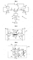
- Fig. 2 schematically depicts an embodiment of a first tension equalizing mechanism 13 according to the invention.
- Provided to the first tension equalizing mechanism are cable portions 4a and 7a of respectively the first cable 4 and the second cable 7.
- the first tension equalizing mechanism 13 comprises interconnected first cable-engaging members in the form of sheaves 14,15. The interconnection is provided by means of beam 16.
- the sheaves 14,15 engage with respective cable portions 4b,7b and are moveable relative to a first reference structure 17 to be mounted on a vessel.
- the moveable direction of the sheaves 14,15 and the beam 16 is indicated by arrow A.
- the cable portions 4b, 7b are guided to and from the sheaves 14, 15 by sheaves 18.
- the sheaves 18 and the first reference structure are fixed relative to the vessel.
- Cable portions 4c,7c are or can be connected to a load connector as shown in Fig. 1 .
- the reference structure 17 acts as a guide for the beam 16.
- the sheaves 14,15 can be aligned such that their respective rotation axes substantially coincide, i.e. are aligned on a common axis. This provides a compact structure.
- a displacement sensor DS in contact with the operating means is provided measuring the displacement D1 of the sheaves 14,15 relative to the first reference structure 17 to correct for non-synchronous raising or lowering of the first and second cable.
- Fig. 2 An advantage of the configuration of Fig. 2 is that the system may be designed symmetrical about a plane equidistant and parallel to both cable portions 4a,7a, said plane also being substantially parallel to the rotation axes of the sheaves 14,15,18.
- Fig. 3 depicts schematically a first tension equalizing mechanism 13 according to another embodiment of the invention.
- the first tension equalizing mechanism comprises sheaves 18 and a first reference structure 17 which are to be mounted to a vessel.
- the sheaves 18 guide the respective cables 4,7 to first cable-engaging members in the form of respective sheaves 14,15.
- the sheaves 14,15 are both connected to a beam 16 via respective connecting means 16a, 16b.
- Said connecting means may be a cable, rod or the like.
- the beam 16 is pivotable about first reference structure 17, as indicated by arrow C, so that the sheaves 14,15 are moveable in respective directions A and B. Due to this configuration, movement of sheave 14 for instance to the right occurs simultaneously, i.e. synchronously, with movement of sheave 15 to the left, i.e. cable 4 is hauled in and cable 7 is paid out. Movement of the sheaves is caused by differential tensions in the first and second cable 4,7 and will equalize said tensions.
- a displacement sensor can be provided to measure the displacement of the sheaves 14,15 to correct for non-synchronous raising and lowering of the first and second cable 4,7.
- This displacement sensor can be provided between the first reference structure 17 and the beam 16 to measure a rotation of said beam 16 relative to the first reference structure, or can be provided between the first reference structure and the connecting means 16a, 16b or sheaves to measure a translation of said connecting means or sheaves relative to the first reference structure. It is even possible to provide the displacement sensor between the sheaves 14,15 to measure the relative mutual position of the sheaves 14,15.
- Fig. 4 depicts schematically a first tension equalizing mechanism 13 according to yet another embodiment of the invention.
- the first tension equalizing mechanism is similar to the system of Fig. 3 .
- the difference between the two embodiments is that the sheaves 14,15 are interconnected via cable portions 16a, 16b that are connected to each other via a rotatable first reference structure 17 in the form of a sheave.
- the rotation of the first reference structure 17 is indicated by arrow 17.
- the sheave 17 is to be fixedly mounted to a vessel as are the sheaves 18, so that sheaves 14,15 can move in opposite directions indicated by arrows A and B and the cable portions 16a, 16b are guided by the sheave 17.
- An advantage of the tension equalizing mechanism of Fig. 4 over the tension equalizing mechanism of Fig. 3 may be that the moving range of the sheaves 14, 15 is larger.
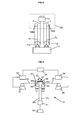
- Fig. 5 depicts schematically a first tension equalizing mechanism 13 and a second tension equalizing mechanism 13' for use in a marine load raising and lowering system that employs four cables 4, 4', 7, 7' and associated winches (not shown).
- Each cable 4, 7, 4',7' is guided by sheaves 18 to a respective sheave 14,15, 14' ,15'.
- the sheaves 14,15 are connected to cable portions 16a, 16b which are connected to each other via a rotatable sheave 17 which acts as a first reference structure.
- the sheave 17 guides the cable portions 16a, 16b thereby allowing movement of the sheaves 14, 15 to equalize tensions in said cables 4,7. Movement of the sheaves 14,15 is indicated by arrows A and B. Rotation of the sheave 17 is indicated by arrow C.
- sheaves 14' ,15' are connected to cable portions 16a', 16b' which are connected to each other via a rotatable sheave 17' which acts as a second reference structure.
- the sheave 17' guides the cable portions 16a', 16b' thereby allowing movement of the sheaves 14', 15' to equalize tensions in said cables 4',7'. Movement of the sheaves 14' and 15' is indicated by arrows A' and B', and rotation of the sheave 17' is indicated by arrow C'.
- the sheaves 17, 17' in turn are moveable relative to a third reference structure 19,19' in the form of sheaves which are to be mounted to a vessel. Movement of the sheaves 17,17' is indicated by arrows D and D'.
- the sheaves 17,17' are interconnected via cable 20 that runs over the sheaves 19,19'. Due to this configuration, the tension in all four cables can be equalized and the four cables can be connected to a load connector with their respective terminal ends.
- the number of cables can easily be increased by providing more tension equalizing mechanisms and interconnecting the respective moveable reference structures.
- the system shown in Fig. 5 can be expanded to eight cables by doubling the configuration, making the respective third reference structures moveable relative to a fourth reference structure and interconnect the respective third reference structures.
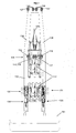
- Fig. 6 depicts a vessel 100 for laying a pipeline on a seabed using a reel lay pipelaying method.
- the vessel comprises a floatable hull 101 and at the stern of the vessel a tiltable tower 110.
- Said tower 110 is tiltable about pivot axis 111 by actuator 112 that can be extended or shortened in a direction F.
- a guide wheel 120 Provided on the tower 110 are a guide wheel 120, a straightener 121 and two tensioners 122.
- a pipeline is unwound from a reel (not shown), run over the guide wheel 120 through the straightener and tensioners to be laid in a substantial vertical orientation, e.g. as in J-lay pipelaying.
- the pipeline is laid through an opening 102 in the hull 101.
- the A&R system comprises a storage winch 132 and a traction winch 131.
- the storage winch generally comprises the main part of a cable 134.
- the tension required to carry a load suspended from the cable 134 is provided by the traction winch 131.
- the traction winch 131 is provided on the tiltable tower, so that the tension generated by the traction winch does no influence tilting of the tower as much as it would if the traction winch was not provided on the tower, but directly on the hull as the storage winch.
- associated driving means and operating means 133 are provided for the storage winch that are configured to provide a hold-back force in the cable 134.
- the cable 134 passes the traction winch, the cable 134 passes a heave compensator 135, a first tension equalizing mechanism 136, and sheaves 137 and 138 at the top of the tower.
- the cable 134 is able to be lowered and raised past the tensioners 122 via the moonpool 102 towards the seabed.
- a similar configuration is provided on the other side of the vessel, so that in total two cables can be lowered and raised. Also not shown is that the cables can be connected to a load connector. As the cables are connected to the load connector with a respective terminal end instead of a equalizing sheave as done in prior art systems, a slender load connector and cable connection can be provided so that it can easily pass the tensioners 122.
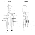
- Fig. 7 depicts the vessel of Fig. 6 , but now seen from the back of the vessel. Shown in Fig. 7 are the hull 101, the tiltable tower 110, the tensioners 122, and the guide wheel 120, which tensioners and guide wheel can be seen through openings in the tower 110.
- FIG. 7 Also shown in Fig. 7 are the symmetrically placed first and second traction winch 131, 131', heave compensators 135, 135', and the sheaves 137,138,137',138' for respectively the first cable 134 and the second cable 134'.
- the first tension equalizing mechanism 136 is provided between the heave compensators 135,135' and the sheaves 137,138,137', 138'.
- the first tension equalizing mechanism comprises sheaves 114,115 of which only one sheave can be seen, as the rotation axes of the sheaves are aligned on a common axis.
- the cables 134, 134' are guided to and from the sheaves 114,115 by sheaves 118 which have been mounted to the tower 110.
- the sheaves 114 and 115 are interconnected and moveable in a direction A relative to a first reference structure 117 mounted to the tower under the effect of differential tensions in the cables 134,134' so as to equalize said tensions.
- Fig. 7 is therefore a more practical implementation of the tension equalizing mechanism according to Fig. 2 .
- the sheaves 138,138' are placed close next to each other, so that the cables 134,134' from there on are also close together.
- This close configuration is advantageous for passing the tensioners, but will increase the chance of entanglement of the cables during lowering and raising of the cables at relatively great depth.
- the cables 134,134' have minimal movement relative to each other, wear is minimized and the close configuration is made possible.
- An advantage of the embodiment according to Fig. 6 and 7 is that the first and second cable when passing sheaves of e.g. the first tension equalizing mechanism are always bent in the same direction.
- Fig. 8 depicts a part of a marine load raising and lowering system according to another embodiment of the invention. Schematically shown are a load connector 11, a vessel 100 and a first tension equalizing mechanism. Fig. 8 shows an alternative way of connecting a first cable 4 and a second cable 7 to the load connector 11 and vessel 100 which falls within the scope of the invention.
- the first and second cable 4,7 extend from the first tension equalizing mechanism 13 towards the load connector 11.
- the load connector 11 is provided with respective sheaves 11 a directing the first and second cable 4,7 back towards the vessel 100.
- the first and second cable are directed back towards the load connector by respective sheaves 100a which are mounted to the vessel 100.
- the terminal ends 4c, 7c of the first and second cable are connected to the load connector 11.
- Fig. 9 depicts a schematic view of a marine load raising and lowering system 31 according to an alternative embodiment of the invention, for use on a vessel, preferably a vessel for laying an offshore pipeline, which system comprises a first winch 32 with first driving means 33 for raising and lowering a first cable 34 from the first winch 32, and a second winch 35 with second driving means 36 with second driving means 36 for raising and lowering a second cable 37 from the second winch 35.
- the first and second driving means 33, 36 can be synchronized by operating means 38 connected to the first and second driving means so as to perform synchronous raising and lowering of the first and second cable.
- the operating means are in this embodiment electronic operating means.
- the first and second cable 34,37 will in practice be very long, but represented here short for reasons of clarity.
- the first and second driving means are electronically and/or mechanically connected to the respective first and second winch 32,35.
- the driving means may include any type of motor.
- the first and second cable 34,37 are connected to a load connector 41 with a respective terminal end 34c, 37c of the first and second cable 34,37.
- the load connector 41 is or can be coupled to a load 42. Due to this configuration, the cable portions 34c, 37c are substantially stationary with respect to each other, so that wear during entanglement of the cables (e.g. in deepwater operations) is minimized.
- a first tension equalizing mechanism 43 is provided through which the first and second cable 34,37 pass.
- the first tension equalizing mechanism 43 comprises a sheave 39 guiding the first cable 34 to and from the first winch 32.
- the first tension equalizing mechanism 43 comprises a sheave 40 guiding the second cable 37 to and from the second winch 35.
- the sheaves 39,40 are both connected to a beam 46 via respective connecting means 46a, 46b.
- Said connecting means may comprise a cable, rod, or the like.
- the sheaves of the first tension equalizing mechanism the sheaves may be interconnected via hydraulic coupling means, such as two interconnected hydraulic cylinders.
- the beam 46 is,pivotable about first reference structure 47, as indicated by arrow D, so that the sheaves 39,40 are moveable in respective directions E1 and E2, representing a combined sideward's and up-/downwards movement. Due to this configuration, movement of sheave 40 for instance to an upward direction to the right occurs simultaneously, i.e. synchronously, with movement of sheave 39 in a downward direction to the right, i.e. cable 37 is hauled in and cable 34 is paid out. Movement of the sheaves is caused by differential tensions in the first and second cable 34,37 and will equalize said tensions.
- An advantage of the curved movements E1, E2 is that when only one cable is being used in the marine load raising and lowering system, this cable is automatically positioned in line with the first reference structure 47.
- This first reference structure 47 may be positioned exactly above the load connector, which is advantageous in view of the distribution of forces.
- the first tension equalizing mechanism 43 thus comprises interconnected sheaves 39, 40 engaging with the first and second cable respectively, wherein said sheaves 39,40 are moveable relative to the first reference structure 47 which is mounted on the vessel.
- the first tension equalizing mechanism is configured to move the sheaves, 39, 40 under the effect of differential tensions in the first and second cable so as to equalize said tensions. This ensures that the load is suspended by both the first and second cable and no overload in one of the cables occurs due to e.g. non-synchronous lowering or raising of the cables.
- the load connector is able to pass smaller openings, e.g. such as openings in tensioners, or moonpools.
- the sheaves 39,40 are aligned such that their respective rotation axes substantially coincide, i.e. are aligned on a common axis. This provides a compact structure.
- a displacement sensor in contact with the operating means is provided measuring the displacement of the sheaves 39,40 relative to the first reference structure 47 to correct for non-synchronous raising or lowering of the first and second cable.
- This displacement sensor can be provided between the first reference structure 47 and the beam 46 to measure a rotation of said beam 46 relative to the first reference structure, or can be provided between the first reference structure and the connecting means 46a, 46b or sheaves to measure a translation of said connecting means or sheaves relative to the first reference structure. It is even possible to provide the displacement sensor between the sheaves 39,40 to measure the relative mutual position of the sheaves 39,40.
- Fig. 9 An advantage of the configuration of Fig. 9 is that the system may be designed symmetrical about a plane equidistant and parallel to both cable portions 34, 37, said plane also being substantially parallel to the rotation axes of the sheaves 39, 40.
- Fig. 9 Another advantage is that the configuration of Fig. 9 can easily be integrated with sheaves already provided at the vessel, such as sheaves 137, 138 on top of the tower 110 as visible in figs. 6 and 7 .
- a tension equalizing mechanism 60 according to the embodiment of fig. 9 is shown.
- a first cable 61 is being guided by sheave 69
- second cable 62 is being guided by sheave 70, guiding the cables to and from respective winches (not shown).
- the sheaves 69,70 are both connected to a connection member 76 via respective connecting means 76a, 76b.
- the connection member 76 is pivotable about a first reference structure 77, mounted to the vessel, via pivot axis 77a, as indicated by arrow G, so that the sheaves 69,70 are moveable in respective directions H1 and H2, representing a combined sideward's and up-/downwards movement.
Claims (15)
- Système d'élévation et d'abaissement de charge marine (1 ; 31) pour une utilisation sur un navire (100), de préférence un navire pour déposer un pipeline au large, lequel système comprend :i. un premier treuil (2 ; 32) comprenant des premiers moyens d'entraînement (3 ; 33 ; 133) pour élever ou abaisser un premier câble (4 ; 34 ; 61 ; 134) à partir du premier treuil ;ii. un deuxième treuil (5 ; 35) comprenant des deuxièmes moyens d'entraînement (6 ; 36 ; 133) pour élever ou abaisser un deuxième câble (7 ; 37 ; 62 ; 134') à partir du deuxième treuil ;iii. des moyens d'actionnement (8 ; 38 ; 133) connectés aux premiers et deuxièmes moyens d'entraînement respectivement des premier et deuxième treuils pour synchroniser les moyens d'entraînement de manière à effectuer une élévation ou un abaissement synchrone des premier et deuxième câbles ;iv. un connecteur de charge (11 ; 41) ;dans lequel
le système comprend en outre un premier mécanisme d'égalisation de tensions (13 ; 43 ; 136) conçu pour égaliser la tension dans les premier et deuxième câbles, ledit premier mécanisme d'égalisation de tensions comportant des premiers éléments de mise en prise avec les câbles interconnectés (14, 15 ; 39, 40 ; 69, 70 ; 114, 115) pour être en prise avec les premier et deuxième câbles, dans lequel lesdits premiers éléments de mise en prise avec les câbles peuvent être déplacés par rapport à une première structure de référence (17 ; 47 ; 77 ; 117) à monter sur le navire ;
et dans lequel ledit premier mécanisme d'égalisation de tensions est configuré pour déplacer les premiers éléments de mise en prise avec les câbles sous l'effet d'une différence de tension dans les premier et deuxième câbles de manière à égaliser lesdites tensions,
caractérisé en ce que les premier et deuxième câbles sont tous deux reliés au connecteur de charge avec une extrémité terminale (4c, 7c ; 34c, 37c) respective des premier et deuxième câbles. - Système selon la revendication 1, dans lequel les premiers éléments de mise en prise avec les câbles comprennent une première poulie à gorge (14 ; 39 ; 69 ; 114) pour être en prise avec le premier câble et une deuxième poulie à gorge (15 ; 40 ; 70 ; 115) pour être en prise avec le deuxième câble.
- Système selon la revendication 2, dans lequel les première et deuxième poulies à gorge (114, 115) sont agencées de sorte que leurs axes de rotation soient alignés avec un axe commun.
- Système selon une ou plusieurs des revendications précédentes, comprenant des poulies à gorge (18 ; 118) en amont et en aval du premier mécanisme d'égalisation de tensions pour guider les premier et deuxième câbles à partir des premiers éléments de mise en prise avec les câbles et vers ceux-ci.
- Système selon une ou plusieurs des revendications précédentes, comprenant un compensateur de houle (135) configuré pour choquer ou border les premier (134) et deuxième (134') câbles pour compenser des mouvements de navire indésirables.
- Système selon une ou plusieurs des revendications précédentes, dans lequel chacun des premier et deuxième treuils est un treuil de traction (131, 131') coopérant avec un treuil de stockage (132) respectif entrainé par des moyens d'actionnement (133) associés qui sont configurés pour fournir une force de retenue dans les premier (134) et deuxième (134') câbles pour le treuil de traction respectif.
- Système selon la revendication 6, dans lequel un capteur de force de retenue est prévu en contact avec les moyens d'actionnement des treuils de stockage afin de synchroniser le mouvement des treuils de stockage avec les premier et deuxième treuils respectifs.
- Système selon une ou plusieurs des revendications précédentes, dans lequel un capteur de déplacement (DS) en contact avec les moyens d'actionnement est prévu pour mesurer le déplacement des premiers éléments de mise en prise avec les câbles pour corriger une élévation ou un abaissement non synchrone des premier et deuxième câbles.
- Système selon une ou plusieurs des revendications précédentes, dans lequel les éléments de mise en prise avec les câbles sont interconnectés en utilisant un câble de liaison (16).
- Système selon la revendication 9, dans lequel la première structure de référence est une poulie à gorge (17), et le câble de liaison s'étend sur ladite poulie à gorge.
- Système selon une ou plusieurs des revendications précédentes, comprenant :- un troisième treuil comprenant des troisièmes moyens d'entraînement pour élever ou abaisser un troisième câble (4') à partir du troisième treuil ;- un quatrième treuil comprenant des quatrièmes moyens d'entraînement pour élever ou abaisser un quatrième câble (7') à partir du quatrième treuil ;- un deuxième mécanisme d'égalisation de tensions (13') ayant des deuxièmes éléments de mise en prise avec les câbles interconnectés (14', 15') pour être en prise avec les troisième et quatrième câbles,dans lequel les deuxièmes éléments de mise en prise avec les câbles peuvent être déplacés par rapport à une deuxième structure de référence (17') à monter sur le navire,
et dans lequel le deuxième système d'égalisation de tensions est configuré pour déplacer les deuxièmes éléments de mise en prise avec les câbles sous l'effet d'une différence de tension dans les troisième et quatrième câbles de manière à égaliser lesdites tensions,
et dans lequel les troisième et quatrième câbles sont reliés chacun au connecteur de charge (11) avec une extrémité terminale respective des troisième et quatrième câbles,
et dans lequel les première et deuxième structures de référence des premier et deuxième mécanismes d'égalisation de tensions sont interconnectées, lesdites première et deuxième structures de référence pouvant être déplacées par rapport à une troisième structure de référence (19, 19') à monter sur le navire de manière à égaliser les tensions dans les premier, deuxième, troisième et quatrième câbles,
et dans lequel, de préférence, les première et deuxième structures de référence sont interconnectées en utilisant un câble de liaison (20). - Système selon une ou plusieurs des revendications précédentes, dans lequel le système d'élévation et d'abaissement de charge fonctionne en tant que système d'abandon et de récupération.
- Procédé pour abaisser une charge d'un navire (100) dans l'eau, par exemple sur le fond marin, de préférence un navire pour déposer un pipeline au large, dans lequel sont utilisés un système d'élévation et d'abaissement de charge marine (1 ; 31) comprenant des premier et deuxième treuils (2, 5 ; 32, 35) avec des premiers et deuxièmes moyens d'entraînement (3, 6 ; 33, 36 ; 133) respectifs pour élever ou abaisser des premier et deuxième câbles (4, 7 ; 34, 37 ; 61, 62 ; 134, 134') à partir des treuils, des moyens d'actionnement (8 ; 38 ; 133) connectés aux premiers et deuxièmes moyens d'entraînement des premier et deuxième treuils pour synchroniser les moyens d'entraînement de manière à effectuer une élévation ou un abaissement synchrone des câbles, et un premier mécanisme d'égalisation de tensions (13 ; 43 ; 136) pour égaliser les tensions dans les premier et deuxième câbles, ledit premier mécanisme d'égalisation de tensions comportant des premiers éléments de mise en prise avec les câbles interconnectés (14, 15 ; 39, 40 ; 69, 70 ; 114, 115) pour être en prise avec les premier et deuxième câbles, dans lequel lesdits premiers éléments de mise en prise avec les câbles peuvent être déplacés par rapport à une première structure de référence (17 ; 47 ; 77 ; 117) à monter sur le navire, et dans lequel le premier mécanisme d'égalisation de tensions est configuré pour déplacer les premiers éléments de mise en prise avec les câbles sous l'effet d'une différence de tension dans les premier et deuxième câbles de manière à égaliser lesdites tensions, ledit procédé comprenant les étapes suivantes :- de liaison d'une extrémité terminale (4c, 7c ; 34c, 37c) respective des câbles à un connecteur de charge (11 ; 41) ;- de liaison d'une charge (12 ; 42) au connecteur de charge ;- d'abaissement des câbles.
- Procédé selon la revendication 13, comprenant les étapes :- de mesure d'un déplacement des premiers éléments de mise en prise avec les câbles ;- d'ajustement des signaux fournis aux moyens d'entraînement par les moyens d'actionnement sur la base dudit déplacement mesuré des premiers éléments de mise en prise avec les câbles pour corriger un abaissement non synchrone des câbles.
- Procédé selon la revendication 13, dans lequel les signaux fournis aux moyens d'entraînement par les moyens d'actionnement sont ajustés de sorte que le déplacement des premiers éléments de mise en prise avec les câbles soit limité à une plage de déplacement prédéterminée.
Applications Claiming Priority (3)
| Application Number | Priority Date | Filing Date | Title |
|---|---|---|---|
| NL2004801A NL2004801C2 (en) | 2010-06-02 | 2010-06-02 | Marine load raising and lowering system. |
| NL2006444 | 2011-03-22 | ||
| PCT/NL2011/050351 WO2011152711A1 (fr) | 2010-06-02 | 2011-05-24 | Système marin de levage et de descente de charges |
Publications (2)
| Publication Number | Publication Date |
|---|---|
| EP2576331A1 EP2576331A1 (fr) | 2013-04-10 |
| EP2576331B1 true EP2576331B1 (fr) | 2015-07-08 |
Family
ID=45066944
Family Applications (1)
| Application Number | Title | Priority Date | Filing Date |
|---|---|---|---|
| EP11722594.6A Active EP2576331B1 (fr) | 2010-06-02 | 2011-05-24 | Système marin de levage et de descente de charges |
Country Status (5)
| Country | Link |
|---|---|
| US (1) | US9103471B2 (fr) |
| EP (1) | EP2576331B1 (fr) |
| CN (1) | CN102917945B (fr) |
| BR (1) | BR112012030605A2 (fr) |
| WO (1) | WO2011152711A1 (fr) |
Families Citing this family (18)
| Publication number | Priority date | Publication date | Assignee | Title |
|---|---|---|---|---|
| ES2426329T3 (es) * | 2010-12-20 | 2013-10-22 | Christopher Bauder | Cabrestante para porporcionar una longitud predeterminada de cable desenrollado |
| KR20140116386A (ko) * | 2011-12-30 | 2014-10-02 | 내셔널 오일웰 바르코 엘.피. | 심층수 너클 붐 크레인 |
| DE202012009836U1 (de) * | 2012-10-15 | 2014-01-16 | Liebherr-Werk Ehingen Gmbh | Vorrichtung zur Beförderung von Personen mittels eines Krans - Kran mit Vorrichtung zur Beförderung von Personen |
| CA2888446C (fr) | 2012-10-17 | 2020-10-27 | Fairfield Industries Incorporated | Appareil de gestion d'une charge utile, procede et applications |
| US9290362B2 (en) | 2012-12-13 | 2016-03-22 | National Oilwell Varco, L.P. | Remote heave compensation system |
| US9624076B2 (en) * | 2014-04-04 | 2017-04-18 | David R. Hall | Synchronized motorized lifting devices for lifting shared loads |
| US9567195B2 (en) * | 2013-05-13 | 2017-02-14 | Hall David R | Load distribution management for groups of motorized lifting devices |
| EP2889251B1 (fr) | 2013-12-30 | 2016-08-24 | Siemens Aktiengesellschaft | Agencement de guidage de charge |
| EP2896589B1 (fr) * | 2014-01-17 | 2016-10-19 | SAL Offshore B.V. | Procédé et appareil |
| WO2018131995A1 (fr) * | 2017-01-16 | 2018-07-19 | Itrec B.V. | Système et procédé de levage en eaux profondes |
| US10669137B2 (en) * | 2017-09-25 | 2020-06-02 | Wt Industries, Llc | Heave compensation system |
| GB2568535B (en) * | 2017-11-20 | 2020-12-02 | Svitzer As | Line handling system for coupling together lines on a tugboat |
| CN110104131B (zh) * | 2018-02-01 | 2021-07-20 | 梯阶电梯工程有限公司 | 升降装置 |
| JP2019156588A (ja) * | 2018-03-14 | 2019-09-19 | 本田技研工業株式会社 | 移動装置 |
| DE102018127953A1 (de) * | 2018-11-08 | 2020-05-14 | Umicore Ag & Co. Kg | Wandflussfilter mit hoher Filtrationseffizienz |
| CN114852282A (zh) * | 2022-05-16 | 2022-08-05 | 中国海洋石油集团有限公司 | 一种适用于半潜式生产平台内侧悬挂立管安装的回接装置 |
| US11761266B1 (en) * | 2022-08-31 | 2023-09-19 | Saudi Arabian Oil Company | Oil rig mast hoisting system |
| CN117263036B (zh) * | 2023-11-20 | 2024-03-01 | 上海博珖机器人有限公司 | 定位方法、装置、系统及光伏阵列半成品安装设备 |
Family Cites Families (19)
| Publication number | Priority date | Publication date | Assignee | Title |
|---|---|---|---|---|
| US3265360A (en) | 1963-06-05 | 1966-08-09 | Tax Johann | Tower crane with auxiliary hoist |
| SE394186B (sv) * | 1968-06-24 | 1977-06-13 | Murmanskoe Vysshee Morekhodnoe | Anordning vid lastkran |
| DE1916644B2 (de) | 1969-04-01 | 1976-04-29 | Fried. Krupp Gmbh, 4300 Essen | Sicherheits-hubwerk, insbesondere fuer einen giesskran |
| US4932541A (en) * | 1989-04-24 | 1990-06-12 | Calspan Corporation | Stabilized shipboard crane |
| US5579931A (en) * | 1989-10-10 | 1996-12-03 | Manitowoc Engineering Company | Liftcrane with synchronous rope operation |
| US6439407B1 (en) * | 1998-07-13 | 2002-08-27 | The United States Of America As Represented By The Secretary Of Commerce | System for stabilizing and controlling a hoisted load |
| US5951227A (en) * | 1998-07-28 | 1999-09-14 | J. Ray Mcdermott, S.A. | Deep water lowering apparatus |
| US6871609B2 (en) * | 2002-08-30 | 2005-03-29 | Itrec B.V. | Multipurpose tower for monohull |
| US6932326B1 (en) * | 2003-06-13 | 2005-08-23 | Richard L. Krabbendam | Method for lifting and transporting a heavy load using a fly-jib |
| US7182550B2 (en) | 2004-05-26 | 2007-02-27 | Heerema Marine Contractors Nederland B.V. | Abandonment and recovery head apparatus |
| NL1026458C2 (nl) * | 2004-06-18 | 2005-12-20 | Itrec Bv | Hijskraan en offshorevaartuig. |
| DE602005026013D1 (de) | 2004-08-02 | 2011-03-03 | Terex Demag Gmbh | Hubseilantrieb mit einer einzigen bodenhakenflasche und zwei seilwinden |
| WO2007030015A2 (fr) * | 2005-09-06 | 2007-03-15 | Gusto B.V. | Systeme de retrofixation pour grues marines, en particulier pour grues marines a lourdes charges |
| US7621697B2 (en) * | 2006-04-19 | 2009-11-24 | Allseas Group S.A. | Abandonment and recovery system and method, and cable connector |
| CN101500930B (zh) * | 2006-08-15 | 2012-05-30 | 海德勒利夫特埃姆克莱德股份有限公司 | 对从线的一端悬入海洋环境的负载物提供升沉补偿的装置和方法 |
| DE602007014414D1 (de) | 2007-06-22 | 2011-06-16 | Itrec Bv | Schiffslastanheb- und -absenksystem |
| FR2919280B1 (fr) * | 2007-07-24 | 2010-02-19 | Soc Et De Rech Et Dev D Automa | Treuil pour la traction de cables, en particulier de cables synthetiques employes en offshore. |
| KR20100072246A (ko) * | 2007-09-14 | 2010-06-30 | 굿크레인 코퍼레이션 | 모션 보정 시스템 |
| GB0819400D0 (en) * | 2008-10-22 | 2008-11-26 | Subsea 7 | Offshore lifting operations |
-
2011
- 2011-05-24 WO PCT/NL2011/050351 patent/WO2011152711A1/fr active Application Filing
- 2011-05-24 EP EP11722594.6A patent/EP2576331B1/fr active Active
- 2011-05-24 BR BR112012030605A patent/BR112012030605A2/pt not_active IP Right Cessation
- 2011-05-24 US US13/701,135 patent/US9103471B2/en active Active
- 2011-05-24 CN CN201180026966.7A patent/CN102917945B/zh active Active
Also Published As
| Publication number | Publication date |
|---|---|
| CN102917945B (zh) | 2016-05-18 |
| US9103471B2 (en) | 2015-08-11 |
| BR112012030605A2 (pt) | 2019-09-24 |
| EP2576331A1 (fr) | 2013-04-10 |
| WO2011152711A1 (fr) | 2011-12-08 |
| US20130129452A1 (en) | 2013-05-23 |
| CN102917945A (zh) | 2013-02-06 |
Similar Documents
| Publication | Publication Date | Title |
|---|---|---|
| EP2576331B1 (fr) | Système marin de levage et de descente de charges | |
| US9759351B2 (en) | Marine pipeline installation system and methods | |
| US9835268B2 (en) | Marine pipeline installation system and method | |
| US8905676B2 (en) | Marine pipeline installation system and methods | |
| CN101156013B (zh) | 安装具有一或多个附件的离岸管线的海上布管系统 | |
| EP1962005B1 (fr) | Système et procédé d'abandon et de récupération et connecteur de câble | |
| CN1325366C (zh) | 传送液体产品的系统 | |
| CA2724519C (fr) | Amelioration d'ensembles de guidage de pipelines | |
| US7806628B2 (en) | Apparatus and methods for laying of elongate articles from a vessel | |
| US20130084135A1 (en) | Apparatus and method of laying pipeline | |
| EP3137801A1 (fr) | Procédé de pose en déroulé de canalisations en mer ainsi que navire et procédé de pose de canalisations | |
| EP2467632B1 (fr) | Navire de pose de canalisations en s en mer | |
| NL2004801C2 (en) | Marine load raising and lowering system. | |
| AU2012241123B2 (en) | Abandonment and recovery system and method, and cable connector |
Legal Events
| Date | Code | Title | Description |
|---|---|---|---|
| PUAI | Public reference made under article 153(3) epc to a published international application that has entered the european phase |
Free format text: ORIGINAL CODE: 0009012 |
|
| 17P | Request for examination filed |
Effective date: 20121228 |
|
| AK | Designated contracting states |
Kind code of ref document: A1 Designated state(s): AL AT BE BG CH CY CZ DE DK EE ES FI FR GB GR HR HU IE IS IT LI LT LU LV MC MK MT NL NO PL PT RO RS SE SI SK SM TR |
|
| DAX | Request for extension of the european patent (deleted) | ||
| GRAP | Despatch of communication of intention to grant a patent |
Free format text: ORIGINAL CODE: EPIDOSNIGR1 |
|
| INTG | Intention to grant announced |
Effective date: 20150127 |
|
| GRAS | Grant fee paid |
Free format text: ORIGINAL CODE: EPIDOSNIGR3 |
|
| GRAA | (expected) grant |
Free format text: ORIGINAL CODE: 0009210 |
|
| AK | Designated contracting states |
Kind code of ref document: B1 Designated state(s): AL AT BE BG CH CY CZ DE DK EE ES FI FR GB GR HR HU IE IS IT LI LT LU LV MC MK MT NL NO PL PT RO RS SE SI SK SM TR |
|
| REG | Reference to a national code |
Ref country code: GB Ref legal event code: FG4D |
|
| REG | Reference to a national code |
Ref country code: AT Ref legal event code: REF Ref document number: 735176 Country of ref document: AT Kind code of ref document: T Effective date: 20150715 Ref country code: CH Ref legal event code: EP |
|
| REG | Reference to a national code |
Ref country code: IE Ref legal event code: FG4D |
|
| REG | Reference to a national code |
Ref country code: DE Ref legal event code: R096 Ref document number: 602011017685 Country of ref document: DE |
|
| REG | Reference to a national code |
Ref country code: NL Ref legal event code: FP |
|
| REG | Reference to a national code |
Ref country code: AT Ref legal event code: MK05 Ref document number: 735176 Country of ref document: AT Kind code of ref document: T Effective date: 20150708 |
|
| REG | Reference to a national code |
Ref country code: LT Ref legal event code: MG4D |
|
| PG25 | Lapsed in a contracting state [announced via postgrant information from national office to epo] |
Ref country code: FI Free format text: LAPSE BECAUSE OF FAILURE TO SUBMIT A TRANSLATION OF THE DESCRIPTION OR TO PAY THE FEE WITHIN THE PRESCRIBED TIME-LIMIT Effective date: 20150708 Ref country code: LV Free format text: LAPSE BECAUSE OF FAILURE TO SUBMIT A TRANSLATION OF THE DESCRIPTION OR TO PAY THE FEE WITHIN THE PRESCRIBED TIME-LIMIT Effective date: 20150708 Ref country code: LT Free format text: LAPSE BECAUSE OF FAILURE TO SUBMIT A TRANSLATION OF THE DESCRIPTION OR TO PAY THE FEE WITHIN THE PRESCRIBED TIME-LIMIT Effective date: 20150708 Ref country code: GR Free format text: LAPSE BECAUSE OF FAILURE TO SUBMIT A TRANSLATION OF THE DESCRIPTION OR TO PAY THE FEE WITHIN THE PRESCRIBED TIME-LIMIT Effective date: 20151009 Ref country code: NO Free format text: LAPSE BECAUSE OF FAILURE TO SUBMIT A TRANSLATION OF THE DESCRIPTION OR TO PAY THE FEE WITHIN THE PRESCRIBED TIME-LIMIT Effective date: 20151008 |
|
| PG25 | Lapsed in a contracting state [announced via postgrant information from national office to epo] |
Ref country code: SE Free format text: LAPSE BECAUSE OF FAILURE TO SUBMIT A TRANSLATION OF THE DESCRIPTION OR TO PAY THE FEE WITHIN THE PRESCRIBED TIME-LIMIT Effective date: 20150708 Ref country code: RS Free format text: LAPSE BECAUSE OF FAILURE TO SUBMIT A TRANSLATION OF THE DESCRIPTION OR TO PAY THE FEE WITHIN THE PRESCRIBED TIME-LIMIT Effective date: 20150708 Ref country code: AT Free format text: LAPSE BECAUSE OF FAILURE TO SUBMIT A TRANSLATION OF THE DESCRIPTION OR TO PAY THE FEE WITHIN THE PRESCRIBED TIME-LIMIT Effective date: 20150708 Ref country code: PL Free format text: LAPSE BECAUSE OF FAILURE TO SUBMIT A TRANSLATION OF THE DESCRIPTION OR TO PAY THE FEE WITHIN THE PRESCRIBED TIME-LIMIT Effective date: 20150708 Ref country code: ES Free format text: LAPSE BECAUSE OF FAILURE TO SUBMIT A TRANSLATION OF THE DESCRIPTION OR TO PAY THE FEE WITHIN THE PRESCRIBED TIME-LIMIT Effective date: 20150708 Ref country code: PT Free format text: LAPSE BECAUSE OF FAILURE TO SUBMIT A TRANSLATION OF THE DESCRIPTION OR TO PAY THE FEE WITHIN THE PRESCRIBED TIME-LIMIT Effective date: 20151109 Ref country code: HR Free format text: LAPSE BECAUSE OF FAILURE TO SUBMIT A TRANSLATION OF THE DESCRIPTION OR TO PAY THE FEE WITHIN THE PRESCRIBED TIME-LIMIT Effective date: 20150708 Ref country code: IS Free format text: LAPSE BECAUSE OF FAILURE TO SUBMIT A TRANSLATION OF THE DESCRIPTION OR TO PAY THE FEE WITHIN THE PRESCRIBED TIME-LIMIT Effective date: 20151108 |
|
| REG | Reference to a national code |
Ref country code: DE Ref legal event code: R097 Ref document number: 602011017685 Country of ref document: DE |
|
| PG25 | Lapsed in a contracting state [announced via postgrant information from national office to epo] |
Ref country code: DK Free format text: LAPSE BECAUSE OF FAILURE TO SUBMIT A TRANSLATION OF THE DESCRIPTION OR TO PAY THE FEE WITHIN THE PRESCRIBED TIME-LIMIT Effective date: 20150708 Ref country code: CZ Free format text: LAPSE BECAUSE OF FAILURE TO SUBMIT A TRANSLATION OF THE DESCRIPTION OR TO PAY THE FEE WITHIN THE PRESCRIBED TIME-LIMIT Effective date: 20150708 Ref country code: IT Free format text: LAPSE BECAUSE OF FAILURE TO SUBMIT A TRANSLATION OF THE DESCRIPTION OR TO PAY THE FEE WITHIN THE PRESCRIBED TIME-LIMIT Effective date: 20150708 Ref country code: EE Free format text: LAPSE BECAUSE OF FAILURE TO SUBMIT A TRANSLATION OF THE DESCRIPTION OR TO PAY THE FEE WITHIN THE PRESCRIBED TIME-LIMIT Effective date: 20150708 Ref country code: SK Free format text: LAPSE BECAUSE OF FAILURE TO SUBMIT A TRANSLATION OF THE DESCRIPTION OR TO PAY THE FEE WITHIN THE PRESCRIBED TIME-LIMIT Effective date: 20150708 |
|
| PLBE | No opposition filed within time limit |
Free format text: ORIGINAL CODE: 0009261 |
|
| STAA | Information on the status of an ep patent application or granted ep patent |
Free format text: STATUS: NO OPPOSITION FILED WITHIN TIME LIMIT |
|
| PG25 | Lapsed in a contracting state [announced via postgrant information from national office to epo] |
Ref country code: RO Free format text: LAPSE BECAUSE OF FAILURE TO SUBMIT A TRANSLATION OF THE DESCRIPTION OR TO PAY THE FEE WITHIN THE PRESCRIBED TIME-LIMIT Effective date: 20150708 |
|
| 26N | No opposition filed |
Effective date: 20160411 |
|
| PG25 | Lapsed in a contracting state [announced via postgrant information from national office to epo] |
Ref country code: BE Free format text: LAPSE BECAUSE OF NON-PAYMENT OF DUE FEES Effective date: 20160531 Ref country code: SI Free format text: LAPSE BECAUSE OF FAILURE TO SUBMIT A TRANSLATION OF THE DESCRIPTION OR TO PAY THE FEE WITHIN THE PRESCRIBED TIME-LIMIT Effective date: 20150708 |
|
| REG | Reference to a national code |
Ref country code: DE Ref legal event code: R119 Ref document number: 602011017685 Country of ref document: DE |
|
| PG25 | Lapsed in a contracting state [announced via postgrant information from national office to epo] |
Ref country code: LU Free format text: LAPSE BECAUSE OF FAILURE TO SUBMIT A TRANSLATION OF THE DESCRIPTION OR TO PAY THE FEE WITHIN THE PRESCRIBED TIME-LIMIT Effective date: 20160524 Ref country code: BE Free format text: LAPSE BECAUSE OF FAILURE TO SUBMIT A TRANSLATION OF THE DESCRIPTION OR TO PAY THE FEE WITHIN THE PRESCRIBED TIME-LIMIT Effective date: 20150708 |
|
| REG | Reference to a national code |
Ref country code: CH Ref legal event code: PL |
|
| PG25 | Lapsed in a contracting state [announced via postgrant information from national office to epo] |
Ref country code: CH Free format text: LAPSE BECAUSE OF NON-PAYMENT OF DUE FEES Effective date: 20160531 Ref country code: LI Free format text: LAPSE BECAUSE OF NON-PAYMENT OF DUE FEES Effective date: 20160531 |
|
| REG | Reference to a national code |
Ref country code: IE Ref legal event code: MM4A |
|
| REG | Reference to a national code |
Ref country code: FR Ref legal event code: ST Effective date: 20170131 |
|
| PG25 | Lapsed in a contracting state [announced via postgrant information from national office to epo] |
Ref country code: FR Free format text: LAPSE BECAUSE OF NON-PAYMENT OF DUE FEES Effective date: 20160531 Ref country code: DE Free format text: LAPSE BECAUSE OF NON-PAYMENT OF DUE FEES Effective date: 20161201 |
|
| PG25 | Lapsed in a contracting state [announced via postgrant information from national office to epo] |
Ref country code: IE Free format text: LAPSE BECAUSE OF NON-PAYMENT OF DUE FEES Effective date: 20160524 |
|
| PG25 | Lapsed in a contracting state [announced via postgrant information from national office to epo] |
Ref country code: SM Free format text: LAPSE BECAUSE OF FAILURE TO SUBMIT A TRANSLATION OF THE DESCRIPTION OR TO PAY THE FEE WITHIN THE PRESCRIBED TIME-LIMIT Effective date: 20150708 Ref country code: HU Free format text: LAPSE BECAUSE OF FAILURE TO SUBMIT A TRANSLATION OF THE DESCRIPTION OR TO PAY THE FEE WITHIN THE PRESCRIBED TIME-LIMIT; INVALID AB INITIO Effective date: 20110524 Ref country code: CY Free format text: LAPSE BECAUSE OF FAILURE TO SUBMIT A TRANSLATION OF THE DESCRIPTION OR TO PAY THE FEE WITHIN THE PRESCRIBED TIME-LIMIT Effective date: 20150708 |
|
| PG25 | Lapsed in a contracting state [announced via postgrant information from national office to epo] |
Ref country code: MC Free format text: LAPSE BECAUSE OF FAILURE TO SUBMIT A TRANSLATION OF THE DESCRIPTION OR TO PAY THE FEE WITHIN THE PRESCRIBED TIME-LIMIT Effective date: 20150708 Ref country code: TR Free format text: LAPSE BECAUSE OF FAILURE TO SUBMIT A TRANSLATION OF THE DESCRIPTION OR TO PAY THE FEE WITHIN THE PRESCRIBED TIME-LIMIT Effective date: 20150708 Ref country code: MK Free format text: LAPSE BECAUSE OF FAILURE TO SUBMIT A TRANSLATION OF THE DESCRIPTION OR TO PAY THE FEE WITHIN THE PRESCRIBED TIME-LIMIT Effective date: 20150708 Ref country code: MT Free format text: LAPSE BECAUSE OF NON-PAYMENT OF DUE FEES Effective date: 20160531 |
|
| PG25 | Lapsed in a contracting state [announced via postgrant information from national office to epo] |
Ref country code: BG Free format text: LAPSE BECAUSE OF FAILURE TO SUBMIT A TRANSLATION OF THE DESCRIPTION OR TO PAY THE FEE WITHIN THE PRESCRIBED TIME-LIMIT Effective date: 20150708 |
|
| PG25 | Lapsed in a contracting state [announced via postgrant information from national office to epo] |
Ref country code: AL Free format text: LAPSE BECAUSE OF FAILURE TO SUBMIT A TRANSLATION OF THE DESCRIPTION OR TO PAY THE FEE WITHIN THE PRESCRIBED TIME-LIMIT Effective date: 20150708 |
|
| PGFP | Annual fee paid to national office [announced via postgrant information from national office to epo] |
Ref country code: NL Payment date: 20230523 Year of fee payment: 13 |
|
| PGFP | Annual fee paid to national office [announced via postgrant information from national office to epo] |
Ref country code: GB Payment date: 20230525 Year of fee payment: 13 |