EP2576271B1 - Power transmission device for electric vehicle - Google Patents
Power transmission device for electric vehicle Download PDFInfo
- Publication number
- EP2576271B1 EP2576271B1 EP11786345.6A EP11786345A EP2576271B1 EP 2576271 B1 EP2576271 B1 EP 2576271B1 EP 11786345 A EP11786345 A EP 11786345A EP 2576271 B1 EP2576271 B1 EP 2576271B1
- Authority
- EP
- European Patent Office
- Prior art keywords
- gear
- power transmission
- transmission device
- shaft
- gear set
- Prior art date
- Legal status (The legal status is an assumption and is not a legal conclusion. Google has not performed a legal analysis and makes no representation as to the accuracy of the status listed.)
- Revoked
Links
Images


Classifications
-
- B—PERFORMING OPERATIONS; TRANSPORTING
- B60—VEHICLES IN GENERAL
- B60K—ARRANGEMENT OR MOUNTING OF PROPULSION UNITS OR OF TRANSMISSIONS IN VEHICLES; ARRANGEMENT OR MOUNTING OF PLURAL DIVERSE PRIME-MOVERS IN VEHICLES; AUXILIARY DRIVES FOR VEHICLES; INSTRUMENTATION OR DASHBOARDS FOR VEHICLES; ARRANGEMENTS IN CONNECTION WITH COOLING, AIR INTAKE, GAS EXHAUST OR FUEL SUPPLY OF PROPULSION UNITS IN VEHICLES
- B60K6/00—Arrangement or mounting of plural diverse prime-movers for mutual or common propulsion, e.g. hybrid propulsion systems comprising electric motors and internal combustion engines
- B60K6/20—Arrangement or mounting of plural diverse prime-movers for mutual or common propulsion, e.g. hybrid propulsion systems comprising electric motors and internal combustion engines the prime-movers consisting of electric motors and internal combustion engines, e.g. HEVs
- B60K6/50—Architecture of the driveline characterised by arrangement or kind of transmission units
-
- H—ELECTRICITY
- H02—GENERATION; CONVERSION OR DISTRIBUTION OF ELECTRIC POWER
- H02K—DYNAMO-ELECTRIC MACHINES
- H02K11/00—Structural association of dynamo-electric machines with electric components or with devices for shielding, monitoring or protection
- H02K11/40—Structural association with grounding devices
-
- B—PERFORMING OPERATIONS; TRANSPORTING
- B60—VEHICLES IN GENERAL
- B60L—PROPULSION OF ELECTRICALLY-PROPELLED VEHICLES; SUPPLYING ELECTRIC POWER FOR AUXILIARY EQUIPMENT OF ELECTRICALLY-PROPELLED VEHICLES; ELECTRODYNAMIC BRAKE SYSTEMS FOR VEHICLES IN GENERAL; MAGNETIC SUSPENSION OR LEVITATION FOR VEHICLES; MONITORING OPERATING VARIABLES OF ELECTRICALLY-PROPELLED VEHICLES; ELECTRIC SAFETY DEVICES FOR ELECTRICALLY-PROPELLED VEHICLES
- B60L15/00—Methods, circuits, or devices for controlling the traction-motor speed of electrically-propelled vehicles
- B60L15/20—Methods, circuits, or devices for controlling the traction-motor speed of electrically-propelled vehicles for control of the vehicle or its driving motor to achieve a desired performance, e.g. speed, torque, programmed variation of speed
- B60L15/2054—Methods, circuits, or devices for controlling the traction-motor speed of electrically-propelled vehicles for control of the vehicle or its driving motor to achieve a desired performance, e.g. speed, torque, programmed variation of speed by controlling transmissions or clutches
-
- B—PERFORMING OPERATIONS; TRANSPORTING
- B60—VEHICLES IN GENERAL
- B60L—PROPULSION OF ELECTRICALLY-PROPELLED VEHICLES; SUPPLYING ELECTRIC POWER FOR AUXILIARY EQUIPMENT OF ELECTRICALLY-PROPELLED VEHICLES; ELECTRODYNAMIC BRAKE SYSTEMS FOR VEHICLES IN GENERAL; MAGNETIC SUSPENSION OR LEVITATION FOR VEHICLES; MONITORING OPERATING VARIABLES OF ELECTRICALLY-PROPELLED VEHICLES; ELECTRIC SAFETY DEVICES FOR ELECTRICALLY-PROPELLED VEHICLES
- B60L50/00—Electric propulsion with power supplied within the vehicle
- B60L50/50—Electric propulsion with power supplied within the vehicle using propulsion power supplied by batteries or fuel cells
- B60L50/60—Electric propulsion with power supplied within the vehicle using propulsion power supplied by batteries or fuel cells using power supplied by batteries
-
- F—MECHANICAL ENGINEERING; LIGHTING; HEATING; WEAPONS; BLASTING
- F16—ENGINEERING ELEMENTS AND UNITS; GENERAL MEASURES FOR PRODUCING AND MAINTAINING EFFECTIVE FUNCTIONING OF MACHINES OR INSTALLATIONS; THERMAL INSULATION IN GENERAL
- F16H—GEARING
- F16H3/00—Toothed gearings for conveying rotary motion with variable gear ratio or for reversing rotary motion
- F16H3/02—Toothed gearings for conveying rotary motion with variable gear ratio or for reversing rotary motion without gears having orbital motion
- F16H3/08—Toothed gearings for conveying rotary motion with variable gear ratio or for reversing rotary motion without gears having orbital motion exclusively or essentially with continuously meshing gears, that can be disengaged from their shafts
- F16H3/087—Toothed gearings for conveying rotary motion with variable gear ratio or for reversing rotary motion without gears having orbital motion exclusively or essentially with continuously meshing gears, that can be disengaged from their shafts characterised by the disposition of the gears
- F16H3/091—Toothed gearings for conveying rotary motion with variable gear ratio or for reversing rotary motion without gears having orbital motion exclusively or essentially with continuously meshing gears, that can be disengaged from their shafts characterised by the disposition of the gears including a single countershaft
-
- F—MECHANICAL ENGINEERING; LIGHTING; HEATING; WEAPONS; BLASTING
- F16—ENGINEERING ELEMENTS AND UNITS; GENERAL MEASURES FOR PRODUCING AND MAINTAINING EFFECTIVE FUNCTIONING OF MACHINES OR INSTALLATIONS; THERMAL INSULATION IN GENERAL
- F16H—GEARING
- F16H57/00—General details of gearing
- F16H57/02—Gearboxes; Mounting gearing therein
-
- H—ELECTRICITY
- H02—GENERATION; CONVERSION OR DISTRIBUTION OF ELECTRIC POWER
- H02K—DYNAMO-ELECTRIC MACHINES
- H02K11/00—Structural association of dynamo-electric machines with electric components or with devices for shielding, monitoring or protection
- H02K11/30—Structural association with control circuits or drive circuits
- H02K11/33—Drive circuits, e.g. power electronics
-
- H—ELECTRICITY
- H02—GENERATION; CONVERSION OR DISTRIBUTION OF ELECTRIC POWER
- H02K—DYNAMO-ELECTRIC MACHINES
- H02K7/00—Arrangements for handling mechanical energy structurally associated with dynamo-electric machines, e.g. structural association with mechanical driving motors or auxiliary dynamo-electric machines
- H02K7/10—Structural association with clutches, brakes, gears, pulleys or mechanical starters
- H02K7/116—Structural association with clutches, brakes, gears, pulleys or mechanical starters with gears
-
- B—PERFORMING OPERATIONS; TRANSPORTING
- B60—VEHICLES IN GENERAL
- B60L—PROPULSION OF ELECTRICALLY-PROPELLED VEHICLES; SUPPLYING ELECTRIC POWER FOR AUXILIARY EQUIPMENT OF ELECTRICALLY-PROPELLED VEHICLES; ELECTRODYNAMIC BRAKE SYSTEMS FOR VEHICLES IN GENERAL; MAGNETIC SUSPENSION OR LEVITATION FOR VEHICLES; MONITORING OPERATING VARIABLES OF ELECTRICALLY-PROPELLED VEHICLES; ELECTRIC SAFETY DEVICES FOR ELECTRICALLY-PROPELLED VEHICLES
- B60L2270/00—Problem solutions or means not otherwise provided for
- B60L2270/10—Emission reduction
- B60L2270/14—Emission reduction of noise
- B60L2270/147—Emission reduction of noise electro magnetic [EMI]
-
- F—MECHANICAL ENGINEERING; LIGHTING; HEATING; WEAPONS; BLASTING
- F16—ENGINEERING ELEMENTS AND UNITS; GENERAL MEASURES FOR PRODUCING AND MAINTAINING EFFECTIVE FUNCTIONING OF MACHINES OR INSTALLATIONS; THERMAL INSULATION IN GENERAL
- F16H—GEARING
- F16H57/00—General details of gearing
- F16H57/02—Gearboxes; Mounting gearing therein
- F16H2057/02034—Gearboxes combined or connected with electric machines
-
- F—MECHANICAL ENGINEERING; LIGHTING; HEATING; WEAPONS; BLASTING
- F16—ENGINEERING ELEMENTS AND UNITS; GENERAL MEASURES FOR PRODUCING AND MAINTAINING EFFECTIVE FUNCTIONING OF MACHINES OR INSTALLATIONS; THERMAL INSULATION IN GENERAL
- F16H—GEARING
- F16H57/00—General details of gearing
- F16H57/02—Gearboxes; Mounting gearing therein
- F16H2057/02039—Gearboxes for particular applications
- F16H2057/02043—Gearboxes for particular applications for vehicle transmissions
-
- H—ELECTRICITY
- H02—GENERATION; CONVERSION OR DISTRIBUTION OF ELECTRIC POWER
- H02K—DYNAMO-ELECTRIC MACHINES
- H02K21/00—Synchronous motors having permanent magnets; Synchronous generators having permanent magnets
- H02K21/12—Synchronous motors having permanent magnets; Synchronous generators having permanent magnets with stationary armatures and rotating magnets
- H02K21/14—Synchronous motors having permanent magnets; Synchronous generators having permanent magnets with stationary armatures and rotating magnets with magnets rotating within the armatures
-
- Y—GENERAL TAGGING OF NEW TECHNOLOGICAL DEVELOPMENTS; GENERAL TAGGING OF CROSS-SECTIONAL TECHNOLOGIES SPANNING OVER SEVERAL SECTIONS OF THE IPC; TECHNICAL SUBJECTS COVERED BY FORMER USPC CROSS-REFERENCE ART COLLECTIONS [XRACs] AND DIGESTS
- Y02—TECHNOLOGIES OR APPLICATIONS FOR MITIGATION OR ADAPTATION AGAINST CLIMATE CHANGE
- Y02T—CLIMATE CHANGE MITIGATION TECHNOLOGIES RELATED TO TRANSPORTATION
- Y02T10/00—Road transport of goods or passengers
- Y02T10/60—Other road transportation technologies with climate change mitigation effect
- Y02T10/64—Electric machine technologies in electromobility
-
- Y—GENERAL TAGGING OF NEW TECHNOLOGICAL DEVELOPMENTS; GENERAL TAGGING OF CROSS-SECTIONAL TECHNOLOGIES SPANNING OVER SEVERAL SECTIONS OF THE IPC; TECHNICAL SUBJECTS COVERED BY FORMER USPC CROSS-REFERENCE ART COLLECTIONS [XRACs] AND DIGESTS
- Y02—TECHNOLOGIES OR APPLICATIONS FOR MITIGATION OR ADAPTATION AGAINST CLIMATE CHANGE
- Y02T—CLIMATE CHANGE MITIGATION TECHNOLOGIES RELATED TO TRANSPORTATION
- Y02T10/00—Road transport of goods or passengers
- Y02T10/60—Other road transportation technologies with climate change mitigation effect
- Y02T10/70—Energy storage systems for electromobility, e.g. batteries
-
- Y—GENERAL TAGGING OF NEW TECHNOLOGICAL DEVELOPMENTS; GENERAL TAGGING OF CROSS-SECTIONAL TECHNOLOGIES SPANNING OVER SEVERAL SECTIONS OF THE IPC; TECHNICAL SUBJECTS COVERED BY FORMER USPC CROSS-REFERENCE ART COLLECTIONS [XRACs] AND DIGESTS
- Y02—TECHNOLOGIES OR APPLICATIONS FOR MITIGATION OR ADAPTATION AGAINST CLIMATE CHANGE
- Y02T—CLIMATE CHANGE MITIGATION TECHNOLOGIES RELATED TO TRANSPORTATION
- Y02T10/00—Road transport of goods or passengers
- Y02T10/60—Other road transportation technologies with climate change mitigation effect
- Y02T10/72—Electric energy management in electromobility
Definitions
- the present invention relates to power transmission devices applicable to electric vehicles with measures for preventing radiation of high-frequency noise.
- an inverter for controlling the motor generates high-frequency noise (or referred to as "radio noise") and a motor drive system including a power transmissions, suspensions and such can be antennas to radiate the high-frequency noise, which cause negative effect on radio reception.
- the present inventors have further studied noise propagation in the vehicle body and have found out that an electric resistance at the brush is not sufficiently low and therefore the noise can flow beyond a part with which the brush contacts. To reduce noise propagation, it is promising to reduce the resistance at the brush. However, reduction in electric resistance at the brush is not readily achieved.
- An object of the present invention is to provide a power transmission device applicable to electric vehicles, which suppresses noise propagation from an inverter through a power transmission to drive shafts and suspensions, thereby reducing noise radiation to the exterior.
- a power transmission device for a vehicle is comprised of a motor housing and a gear casing; a motor housed in the motor housing and including a rotor shaft and a stator having an electromagnetic coil; an inverter configured to generate an alternating current, the inverter being connected with the coil to controllably rotate the rotor shaft relative to the stator; a gear set carried by the gear casing and including an input shaft coupled with and rotated by the rotor shaft, an output shaft and gears so meshed as to transmit torque of the input shaft to the output shaft; and a grounding path electrically connecting a connection point on the gear set with a body of the vehicle, the connection point being so disposed as to have the input shaft electrically interposed between the connection point and the rotor shaft, to increase an electric resistance there between .
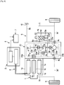
- FIG. 1 a power transmission device for an electric vehicle according to a first embodiment of the present invention will be described.
- the power transmission device of the first embodiment is comprised of a motor 1, an inverter 2, a first gear set 3 including a plurality of couplings and meshing parts 4 functioning as resistors, and a grounding path 5.
- the motor 1 is comprised of a motor housing 1a, a rotor shaft 1b rotatably supported by the motor housing 1a, a rotor 1c drivingly coupled with the rotor shaft 1b, and stators 1e fixed to the motor housing 1a.
- Each stator 1e has an electric coil 1d coiled therearound.
- the rotor 1c is accordingly comprised of a plurality of permanent magnets, thereby being rotated by a magnetic field generated by the coils 1d.
- any permanent magnet synchronous motor may be applied to the motor 1.
- the inverter 2 is connected with the motor coils 1d of the motor 1 via a three-phase power cable 6, and is in turn connected with a secondary battery 7 via a power cable 8.
- the inverter 2 includes switching devices to convert direct current supplied by the battery 7 into alternating current and further convert alternating current from the motor 1 into direct current.
- the inverter 2 generates alternating current to drive the motor 1 when the vehicle gathers speed, and further regenerates electric power out of the kinetic energy of the vehicle when the vehicle decelerates.
- the first gear set 3 is a reduction gear set and intervenes between a rotor shaft 1b and output shafts 3d respectively coupled with wheels 9, thereby transmitting torque from the rotor shaft 1b to the output shafts 3d with reducing its speed.
- the first gear set 3 may be a speed-up gear set or an isokinetic gear set.
- the first gear set 3 includes a combination of shafts and gears, all of which are in general carried by a gear casing 3a.
- the shafts include an input shaft 3b drivingly coupled with and rotated by the rotor shaft 1b, a counter shaft 3c, and output shafts 3d for driving wheels 9 in general.
- the gears include an input gear 3e on the shaft 3b, a first counter gear 3f on the shaft 3c meshing with the input gear 3e, a second counter gear 3g also on the shaft 3c, and a drive gear 3h on the output shafts 3d meshing with the second counter gear 3g.
- a differential gear 3i intervenes between the drive gear 3h and the output shafts 3d.
- the gears are so meshed as to transmit torque of the input shaft 3b to the output shafts 3d.
- the gear set 3 may be comprised of a smaller or greater number of shafts and gears.
- the gear set 3 includes a plurality of meshing parts, namely a meshing part 4d at which the gear 3e meshes with the gear 3f, and a meshing part 4e at which the gear 3g meshes with the gear 3h.
- These meshing parts 4d and 4e inherently have considerably greater electric resistances than those of the shafts and gears, thereby functioning as resistors.
- the gear set 3 may further have a spline coupling 4a for coupling with the rotor shaft 1b, and output couplings 4b, 4c for respectively coupling with drive shafts 3d', these couplings 4a, 4b, 4c also function as resistors.
- the grounding path 5 includes one or more brushes 5a, one or more lead lines 5e and a connection line 5b.
- the brushes 5a are kept in slidable contact with, and are therefore electrically connected with, an end portion 3c' of the counter shaft 3c.
- the lead lines 5e are electrically connected with both the brushes 5a and the gear casing 3a.
- the connection line 5b establishes electric connection of the gear casing 3a with a body 10 of the vehicle.
- the brushes 5a, the lead lines 5e and the connection line 5b in combination with the gear casing 3a constitute the grounding path 5 for electrically grounding a part of the first gear set 3.
- left and right suspensions 11 are further illustrated.
- the counter shaft 3c is rotatably supported by the gear casing 3a with having a ball bearing 13 interposed therebetween.
- the counter shaft 3c is, within a gear chamber 3j inside the casing 3a, splined to drivingly engage with the first counter gear 3f.
- an oil seal 14 is provided at an opposite side relative to the bearing 13, so as to seal oil within the casing 3a.
- Any anti-displacement means such as a snap ring 15 is secured to the end portion 3c' of the counter shaft 3c.
- the end portion 3c' is preferably further elongated outward, where the brushes 5a, preferably provided in pair, are kept in contact with the counter shaft 3c.
- a cover 16 is attached to the casing 3a so as to cover the brushes 5a and the end portion 3c'.
- the cover 16 and the gear casing 3a enclose a brush chamber 17 and the cover 16 is preferably comprised of a breather connector 12 to assure air ventilation.
- a brush case 5c of an electrically non-conductive material is secured to the gear casing 3a by means of an elongated portion 3a' of the casing 3a with a securing means such as a bolt.
- a securing means such as a bolt.
- Each brush 5a along with a compressed spring 5d is housed in the brush case 5c and is thus urged toward the end portion 3c' of the counter shaft 3c.
- the lead lines 5e connected with the brushes 5a are led out of the brush case 5c and are electrically connected with the gear casing 3a.
- an inverter for controlling a motor generates high-frequency noise and a motor drive system including a power transmission system and suspensions can be antennas to radiate the high-frequency noise, which causes negative effect on radio reception.
- FIG. 3 schematically illustrates such noise radiation.
- An inverter includes switching devices which repeat turn on and off current flow, thereby generating alternating current. Each time the switching devices turn on current flow, sharp rising edges occur in the current flow and in turn cause high-frequency noise.
- the high-frequency noise flows through a power cable PC and a motor coil MC to a rotor shaft MS of a motor M. Without any measure for high-frequency noise, the noise further flows through an input gear IG, a counter shaft CS, a differential gear DG and drive shafts DS to suspensions S of the vehicle.
- both increase in the resistance ZR and decrease in the resistance ZB are effective in suppression of the voltage V2 at the connection point CP, which leads to suppression of noise radiation as described above.
- the coupling 4a and the meshing part 4d are electrically interposed between the rotor shaft 1b and the part where the grounded brushes 5a electrically contacts with the counter shaft 3c.
- the coupling 4a and the meshing part 4d have considerably high resistance as described earlier.
- the resistance ZR is made relatively high, thereby reducing the noise voltage V2 and suppressing the noise current flowing beyond the connection point CP.
- the brushes 5a may be disposed in any location in the first gear set 3 as far as one or more electrically resistive elements are electrically interposed between the rotor shaft 1b and a part where the grounded brushes 5a electrically contacts with the first gear set 3.
- resistive elements meshing parts between any meshing gears, couplings, and any resistor connected in series in a shaft or a gear can be exemplified. This structure effectively suppresses noise radiation.
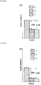
- FIGs. 5A and 5B Each figure compares three cases of; (A) the rotor shaft 1b is grounded at a location A shown in FIG. 1 ; (B) the input shaft 3b is grounded at a location B; and (C) the counter shaft 3c is grounded at a location C (the present embodiment).
- FIG. 5A shows cases where a vehicle runs at 5km/h
- FIG. 5B shows case where a vehicle runs at 40km/h.
- Each axis of ordinate represents radiated noise intensities measured in decibels relative to a standard intensity.
- FIGs. 5A and 5b illustrate that the case (A) (the rotor shaft 1b is grounded) provides the greatest noise intensities.
- the case (B) (the input shaft 3b is grounded) as compared with the case (A), the noise intensities are suppressed.
- the case (C) (the counter shaft 3c is grounded), the noise intensities are further suppressed.
- the present embodiment further provides the following effects.
- the oil seal 14 intervenes between the gear chamber 3j in which lubricant oil circulates and the brush chamber 17 which houses the brushes 5a, thereby separating these chambers.
- the oil does not ill-affect electrical continuity between the brushes 5a and the counter shaft 3c, and further fragments rubbed off from the brushes 5a or the counter shaft 3c do not ill-affect lubrication in the gear chamber 3j.
- FIG. 6 illustrates a second embodiment in which an electric vehicle includes a second gear set 23 of a reduction gear set with four shafts.
- the second gear set 23 intervenes between a rotor shaft 1b and output shafts 23e coupled with wheels 9, thereby transmitting torque from the rotor shaft 1b to the output shafts 23e with reducing its speed.
- the second gear set 23 includes a combination of shafts and meshing gears, all of which are in general carried by a gear casing 23a.
- the shafts include an input shaft 23b drivingly coupled with and rotated by the rotor shaft 1b, a first counter shaft 23c, a second counter shaft 23d and output shafts 23e for driving wheels 9 in general.
- the gears include an input gear 23f on the input shaft 23b, first counter gears 23g, 23h on the first counter shaft 23c, one of which meshes with the input gear 23f, second counter gears 23i, 23j on the second counter shaft 23d, one of which meshes with the first counter gear 23h, and a drive gear 23h on the output shafts 23e meshing with the second counter gear 23j.
- a differential gear 23m intervenes between the drive gear 3h and the output shafts 23e.
- the gears are so meshed as to transmit torque of the input shaft 23b to the output shafts 23e.
- the gear set 23 may be comprised of a smaller or greater number of shafts and gears.
- the gear set 23 includes a spline coupling 4a, meshing parts 4d, 4e, 4f where gears 23f, 23g, 23h, 23i, 23j, 23k mesh with each other, and output couplings 4b, 4c, all of which are electrically resistive.
- a grounding path 5 includes one or more brushes 5a in slidable contact with an end portion 23d' of the second counter shaft 23d.
- the brushes 5a are grounded through the gear casing 3a and the connection line 5b, thereby grounding the second counter shaft 23d.
- location of the brushes 5a may be modified so as to electrically ground any other shaft 23b, 23c or 23e.
- the second embodiment provides the same effects as those of the first embodiment.
- FIG. 7 illustrates a third embodiment in which a gear set 33 with planetary gearing is used.
- the power transmission device of the third embodiment is comprised of a motor 1, an inverter 2, the gear set 33 including electrically resistive elements 4, and a grounding path 5. Aside from the gear set 33, those as described earlier can be applied to these components 1, 2 and 5 and therefore detailed descriptions thereof will be omitted.
- the gear set 33 intervenes between a rotor shaft 1b of the motor 1 and output shafts 33d, thereby transmitting torque from the rotor shaft 1b to the output shafts 33d.
- the gear set 33 includes a combination of shafts and meshing gears, all of which are in general carried by a gear casing 33a.
- the shafts include an input shaft 33b, a cylindrical shaft 33c coaxial with the input shaft 33b and an output shaft 33d.
- the gears include a planetary gear set of a single pinion type, which is comprised of a sun gear 33e, pinions 33f meshing with and revolving about the sun gear 33e, a ring gear 33g meshing with the pinions 33f, and an output gear 33h for output.
- a pinion carrier 33k holds the pinions 33f and the cylindrical shaft 33c is secured thereto.
- the gear set 33 further includes a differential gear having a drive gear 33i meshing with the output gear 33h.
- the ring gear 33g is secured to gear casing 33a by means of a connection member 5f as shown in FIGs. 7 and 8A . Therefore, when the sun gear 33e rotates, the pinions 33f along with the pinion carrier 33k revolves with reduced revolution relative to the sun gear 33e on the basis of the stationary ring gear 33g as shown in FIG. 8B . Thus torque with reduced speed is output to the output gear 33h and further transmitted to the output shafts 33d via the differential gear.
- connection member 5f also establishes electric connection between the ring gear 33g and the gear casing 33a.
- a connection line 5b electrically connects the gear casing 33a with the body 10 of the vehicle.
- connection member 5f, the gear casing 33a and the connection line 5b constitute the grounding path 5 for electrically grounding the ring gear 33f.
- Both a meshing part 4d between the gears 33e and 33f and a meshing part 4f between the gears 33h and 33i are electrically resistive.
- the gear set 3 may further have a spline coupling 4a for coupling with the rotor shaft 1b and output couplings 4b, 4c for respectively coupling with wheel shafts 3d', the couplings 4a, 4b, 4c are also resistive.
- connection member 5f is electrically connected with the ring gear 33g, at least the meshing parts 4d, 4e and the coupling 4a, as electrically resistive elements, are interposed between the rotor shaft 1b and the connection member 5f.
- the resistance ZR in its equivalent circuit shown in FIG. 4 is made relatively higher. Therefore the noise voltage V2 is reduced as described above and then noise radiation is suppressed.
- FIG. 9 illustrates one of such modifications.
- a resistor R is connected in series in the input shaft 33b. As the resistor R increases an electric resistance on the line of the input shaft 33b and the counter shaft CS interposed between brushes B and a rotor shaft (not shown), noise flowing toward the drive shaft DS is suppressed. Location of the resistor R may be alternatively changed.
- any means other than the brushes 5a and the connection member 5f may be alternatively used as far as one or more electrically resistive elements are electrically interposed between the motor and the means.
- teachings as described above can be also applied to continuously variable transmissions. Further the teachings can be also applied to so-called hybrid vehicles, fuel cell vehicles, or any other vehicles where noise radiation is concerned.
- a power transmission device applicable to electric vehicles which suppresses noise propagation from an inverter through a power transmission device to drive shafts and suspensions, thereby reducing noise radiation to the exterior.
Landscapes
- Engineering & Computer Science (AREA)
- Power Engineering (AREA)
- Mechanical Engineering (AREA)
- Transportation (AREA)
- General Engineering & Computer Science (AREA)
- Life Sciences & Earth Sciences (AREA)
- Sustainable Development (AREA)
- Sustainable Energy (AREA)
- Microelectronics & Electronic Packaging (AREA)
- Chemical & Material Sciences (AREA)
- Combustion & Propulsion (AREA)
- Electric Propulsion And Braking For Vehicles (AREA)
- Motor Or Generator Frames (AREA)
- Connection Of Motors, Electrical Generators, Mechanical Devices, And The Like (AREA)
- Motor Power Transmission Devices (AREA)
- General Details Of Gearings (AREA)
Description
- The present invention relates to power transmission devices applicable to electric vehicles with measures for preventing radiation of high-frequency noise.
- It is known that, in an electric vehicle equipped with a motor as a driving power source, an inverter for controlling the motor generates high-frequency noise (or referred to as "radio noise") and a motor drive system including a power transmissions, suspensions and such can be antennas to radiate the high-frequency noise, which cause negative effect on radio reception.
- The following document discloses a related art, which proposes having a brush in electrical contact with an output shaft of a motor and grounding the brush via a vehicle body. Other power transmission devices for vehicles are known from PTL 2 and
PTL 3. -
- PTL 1: Japanese Patent Unexamined Application Laid-open No.
2006-320129 - PTL 2:
JP 2000 244180 A - PTL 3:
JP 2009 029326 A - In the aforementioned related art, it is expected that the output shaft along with the motor is successfully grounded via a brush and thereby noise propagation is prevented. However, the present inventors have found out that the noise further leaks out of the output shaft toward a power transmission system and suspensions and is there radiated outward.
- The present inventors have further studied noise propagation in the vehicle body and have found out that an electric resistance at the brush is not sufficiently low and therefore the noise can flow beyond a part with which the brush contacts. To reduce noise propagation, it is promising to reduce the resistance at the brush. However, reduction in electric resistance at the brush is not readily achieved.
- The present invention has been achieved in view of the aforementioned problem. An object of the present invention is to provide a power transmission device applicable to electric vehicles, which suppresses noise propagation from an inverter through a power transmission to drive shafts and suspensions, thereby reducing noise radiation to the exterior.
- According to an aspect of the present invention, a power transmission device for a vehicle is comprised of a motor housing and a gear casing; a motor housed in the motor housing and including a rotor shaft and a stator having an electromagnetic coil; an inverter configured to generate an alternating current, the inverter being connected with the coil to controllably rotate the rotor shaft relative to the stator; a gear set carried by the gear casing and including an input shaft coupled with and rotated by the rotor shaft, an output shaft and gears so meshed as to transmit torque of the input shaft to the output shaft; and a grounding path electrically connecting a connection point on the gear set with a body of the vehicle, the connection point being so disposed as to have the input shaft electrically interposed between the connection point and the rotor shaft, to increase an electric resistance there between .
-
- [
fig. 1] FIG. 1 is a schematic view of an electric vehicle with a power transmission device according to a first embodiment of the present invention, which in particular shows a relation among the power transmission device, wheels and the ground. - [
fig.2]FIG. 2 is an enlarged cross sectional view of the power transmission device around brushes. - [
fig.3]FIG. 3 is a schematic drawing of an electric vehicle without measures for high-frequency noise, which schematically shows propagation pathways of the noise. - [
fig.4]FIG. 4 is a schematic drawing of an equivalent circuit with respect to the electric vehicle with the power transmission device according to the first embodiment. - [
fig.5A]FIG. 5A demonstrates noise suppression when the electric vehicle runs at 5 km/h. - [
fig.5B]FIG. 5B demonstrates noise suppression when the electric vehicle runs at 40 km/h. - [
fig.6]FIG. 6 is a schematic view of an electric vehicle with a power transmission device according to a second embodiment of the present invention. - [
fig.7]FIG. 7 is a schematic view of an electric vehicle with a power transmission device according to a third embodiment of the present invention. - [
fig. 8A] FIG. 8A shows a planetary gear used in the power transmission device according to the third embodiment. - [
fig.8B]FIG. 8B shows revolutions of respective gear members of the planetary gear. - [
fig.9]FIG. 9 is a schematic view of a resistor and related members according to a modified embodiment. - Exemplary embodiments of the present invention will be described hereinafter with reference to the appended drawings.
- Referring to
FIG. 1 , a power transmission device for an electric vehicle according to a first embodiment of the present invention will be described. - The power transmission device of the first embodiment is comprised of a motor 1, an inverter 2, a
first gear set 3 including a plurality of couplings and meshingparts 4 functioning as resistors, and a grounding path 5. - The motor 1 is comprised of a
motor housing 1a, arotor shaft 1b rotatably supported by themotor housing 1a, arotor 1c drivingly coupled with therotor shaft 1b, andstators 1e fixed to themotor housing 1a. Eachstator 1e has anelectric coil 1d coiled therearound. Therotor 1c is accordingly comprised of a plurality of permanent magnets, thereby being rotated by a magnetic field generated by thecoils 1d. Specifically, any permanent magnet synchronous motor may be applied to the motor 1. - The inverter 2 is connected with the
motor coils 1d of the motor 1 via a three-phase power cable 6, and is in turn connected with a secondary battery 7 via apower cable 8. The inverter 2 includes switching devices to convert direct current supplied by the battery 7 into alternating current and further convert alternating current from the motor 1 into direct current. Thus the inverter 2 generates alternating current to drive the motor 1 when the vehicle gathers speed, and further regenerates electric power out of the kinetic energy of the vehicle when the vehicle decelerates. - The
first gear set 3 is a reduction gear set and intervenes between arotor shaft 1b andoutput shafts 3d respectively coupled withwheels 9, thereby transmitting torque from therotor shaft 1b to theoutput shafts 3d with reducing its speed. Of course, thefirst gear set 3 may be a speed-up gear set or an isokinetic gear set. - The
first gear set 3 includes a combination of shafts and gears, all of which are in general carried by agear casing 3a. The shafts include aninput shaft 3b drivingly coupled with and rotated by therotor shaft 1b, acounter shaft 3c, andoutput shafts 3d fordriving wheels 9 in general. The gears include aninput gear 3e on theshaft 3b, afirst counter gear 3f on theshaft 3c meshing with theinput gear 3e, asecond counter gear 3g also on theshaft 3c, and adrive gear 3h on theoutput shafts 3d meshing with thesecond counter gear 3g. To allow differential motion between the right and left wheels, adifferential gear 3i intervenes between thedrive gear 3h and theoutput shafts 3d. Thus the gears are so meshed as to transmit torque of theinput shaft 3b to theoutput shafts 3d. Of course, thegear set 3 may be comprised of a smaller or greater number of shafts and gears. - As will be understood from the above description, the
gear set 3 includes a plurality of meshing parts, namely ameshing part 4d at which thegear 3e meshes with thegear 3f, and ameshing part 4e at which thegear 3g meshes with thegear 3h. These meshingparts gear set 3 may further have aspline coupling 4a for coupling with therotor shaft 1b, andoutput couplings drive shafts 3d', thesecouplings - The grounding path 5 includes one or
more brushes 5a, one ormore lead lines 5e and aconnection line 5b. Thebrushes 5a are kept in slidable contact with, and are therefore electrically connected with, anend portion 3c' of thecounter shaft 3c. Thelead lines 5e are electrically connected with both thebrushes 5a and thegear casing 3a. Theconnection line 5b establishes electric connection of thegear casing 3a with abody 10 of the vehicle. Thus thebrushes 5a, thelead lines 5e and theconnection line 5b in combination with thegear casing 3a constitute the grounding path 5 for electrically grounding a part of thefirst gear set 3. Meanwhile, inFIG. 1 , left andright suspensions 11 are further illustrated. - Details of the
brushes 5a and related parts will be further described with reference toFIG. 2 , hereinafter. - The
counter shaft 3c is rotatably supported by thegear casing 3a with having aball bearing 13 interposed therebetween. Thecounter shaft 3c is, within agear chamber 3j inside thecasing 3a, splined to drivingly engage with thefirst counter gear 3f. At an opposite side relative to thebearing 13, anoil seal 14 is provided so as to seal oil within thecasing 3a. Any anti-displacement means such as asnap ring 15 is secured to theend portion 3c' of thecounter shaft 3c. Theend portion 3c' is preferably further elongated outward, where thebrushes 5a, preferably provided in pair, are kept in contact with thecounter shaft 3c. - A
cover 16 is attached to thecasing 3a so as to cover thebrushes 5a and theend portion 3c'. Thecover 16 and thegear casing 3a enclose abrush chamber 17 and thecover 16 is preferably comprised of abreather connector 12 to assure air ventilation. - Within the
brush chamber 17, a brush case 5c of an electrically non-conductive material is secured to thegear casing 3a by means of anelongated portion 3a' of thecasing 3a with a securing means such as a bolt. Eachbrush 5a along with acompressed spring 5d is housed in the brush case 5c and is thus urged toward theend portion 3c' of thecounter shaft 3c. Thelead lines 5e connected with thebrushes 5a are led out of the brush case 5c and are electrically connected with thegear casing 3a. - How the present embodiment suppresses noise radiation will be described hereinafter.
- As described above, it is known that, in an electric vehicle or a so-called hybrid vehicle, an inverter for controlling a motor generates high-frequency noise and a motor drive system including a power transmission system and suspensions can be antennas to radiate the high-frequency noise, which causes negative effect on radio reception.
-
FIG. 3 schematically illustrates such noise radiation. An inverter includes switching devices which repeat turn on and off current flow, thereby generating alternating current. Each time the switching devices turn on current flow, sharp rising edges occur in the current flow and in turn cause high-frequency noise. The high-frequency noise, as illustrated by thick lines inFIG. 3 , flows through a power cable PC and a motor coil MC to a rotor shaft MS of a motor M. Without any measure for high-frequency noise, the noise further flows through an input gear IG, a counter shaft CS, a differential gear DG and drive shafts DS to suspensions S of the vehicle. These noise conduction paths as a whole function as an antenna for radiating the noise to the exterior. - If a brush is provided and grounded, an equivalent circuit can be drawn in a way as shown in
FIG. 4 . An output voltage V2 of the noise present at a connection point CP where the brush contacts with any part of the power transmission device is represented by an equation:
rotor shaft 1b, ZR represents a resistance present between theshaft 1b and the connection point CP, and ZB represents a resistance through the brush toward the ground. - The lower the voltage V2 is, the less the noise current flows beyond the connection point toward the drive shaft DS. Thus suppression of the voltage V2 is required in order to suppress noise radiation.
- As will be understood from the above equation (1), both increase in the resistance ZR and decrease in the resistance ZB are effective in suppression of the voltage V2 at the connection point CP, which leads to suppression of noise radiation as described above.
- If a brush contacts with a rotor shaft as with the art disclosed in the PTL 1, substantially there is not a resistive element between the
rotor shaft 1b and the connection point CP. Thus the resistance ZR is relatively low and the resistance ZB is relatively high. A considerable amount of noise may flow beyond the connection point CP toward the drive shaft DS, where the noise is radiated. - In contrast, according to the present embodiment, as the
brushes 5a are kept in electrical contact with theend portion 3c' of thecounter shaft 3c, thecoupling 4a and themeshing part 4d are electrically interposed between therotor shaft 1b and the part where the grounded brushes 5a electrically contacts with thecounter shaft 3c. Thecoupling 4a and themeshing part 4d have considerably high resistance as described earlier. Thus the resistance ZR is made relatively high, thereby reducing the noise voltage V2 and suppressing the noise current flowing beyond the connection point CP. - The
brushes 5a may be disposed in any location in the first gear set 3 as far as one or more electrically resistive elements are electrically interposed between therotor shaft 1b and a part where the grounded brushes 5a electrically contacts with thefirst gear set 3. As the resistive elements, meshing parts between any meshing gears, couplings, and any resistor connected in series in a shaft or a gear can be exemplified. This structure effectively suppresses noise radiation. - The effect of noise suppression is further demonstrated in
FIGs. 5A and 5B . Each figure compares three cases of; (A) therotor shaft 1b is grounded at a location A shown inFIG. 1 ; (B) theinput shaft 3b is grounded at a location B; and (C) thecounter shaft 3c is grounded at a location C (the present embodiment).FIG. 5A shows cases where a vehicle runs at 5km/h, andFIG. 5B shows case where a vehicle runs at 40km/h. Each axis of ordinate represents radiated noise intensities measured in decibels relative to a standard intensity. - Both
FIGs. 5A and 5b illustrate that the case (A) (therotor shaft 1b is grounded) provides the greatest noise intensities. In the case (B) (theinput shaft 3b is grounded) as compared with the case (A), the noise intensities are suppressed. In the case (C) (thecounter shaft 3c is grounded), the noise intensities are further suppressed. - As well as the aforementioned effects, the present embodiment further provides the following effects.
- The
oil seal 14 intervenes between thegear chamber 3j in which lubricant oil circulates and thebrush chamber 17 which houses thebrushes 5a, thereby separating these chambers. Thus the oil does not ill-affect electrical continuity between thebrushes 5a and thecounter shaft 3c, and further fragments rubbed off from thebrushes 5a or thecounter shaft 3c do not ill-affect lubrication in thegear chamber 3j. - As the
breather 12 establishes ventilation between thebrush chamber 17 and the exterior, pressure difference therebetween is effectively prevented. This results in prevention of oil leakage to thebrush chamber 17, which may be driven by differential pressure. - In the aforementioned first embodiment, the reduction gear with three shafts is used. A gear set with four or more shafts may be alternatively used.
FIG. 6 illustrates a second embodiment in which an electric vehicle includes a second gear set 23 of a reduction gear set with four shafts. - The second gear set 23 intervenes between a
rotor shaft 1b andoutput shafts 23e coupled withwheels 9, thereby transmitting torque from therotor shaft 1b to theoutput shafts 23e with reducing its speed. - The second gear set 23 includes a combination of shafts and meshing gears, all of which are in general carried by a
gear casing 23a. The shafts include aninput shaft 23b drivingly coupled with and rotated by therotor shaft 1b, a first counter shaft 23c, asecond counter shaft 23d andoutput shafts 23e for drivingwheels 9 in general. The gears include aninput gear 23f on theinput shaft 23b, first counter gears 23g, 23h on the first counter shaft 23c, one of which meshes with theinput gear 23f, second counter gears 23i, 23j on thesecond counter shaft 23d, one of which meshes with thefirst counter gear 23h, and adrive gear 23h on theoutput shafts 23e meshing with the second counter gear 23j. To allow differential motion between the right and left wheels, adifferential gear 23m intervenes between thedrive gear 3h and theoutput shafts 23e. Thus the gears are so meshed as to transmit torque of theinput shaft 23b to theoutput shafts 23e. Of course, the gear set 23 may be comprised of a smaller or greater number of shafts and gears. - The gear set 23 includes a
spline coupling 4a, meshingparts gears output couplings - A grounding path 5 includes one or
more brushes 5a in slidable contact with anend portion 23d' of thesecond counter shaft 23d. Thebrushes 5a are grounded through thegear casing 3a and theconnection line 5b, thereby grounding thesecond counter shaft 23d. Of course, location of thebrushes 5a may be modified so as to electrically ground anyother shaft - The second embodiment provides the same effects as those of the first embodiment.
- Alternatively, epicyclic gearing or planetary gearing may be used instead of the aforementioned reduction gears of a parallel shaft system.
FIG. 7 illustrates a third embodiment in which a gear set 33 with planetary gearing is used. - The power transmission device of the third embodiment is comprised of a motor 1, an inverter 2, the gear set 33 including electrically
resistive elements 4, and a grounding path 5. Aside from the gear set 33, those as described earlier can be applied to these components 1, 2 and 5 and therefore detailed descriptions thereof will be omitted. - The gear set 33 intervenes between a
rotor shaft 1b of the motor 1 andoutput shafts 33d, thereby transmitting torque from therotor shaft 1b to theoutput shafts 33d. - The gear set 33 includes a combination of shafts and meshing gears, all of which are in general carried by a
gear casing 33a. The shafts include aninput shaft 33b, acylindrical shaft 33c coaxial with theinput shaft 33b and anoutput shaft 33d. The gears include a planetary gear set of a single pinion type, which is comprised of asun gear 33e,pinions 33f meshing with and revolving about thesun gear 33e, aring gear 33g meshing with thepinions 33f, and anoutput gear 33h for output. Apinion carrier 33k holds thepinions 33f and thecylindrical shaft 33c is secured thereto. The gear set 33 further includes a differential gear having adrive gear 33i meshing with theoutput gear 33h. - The
ring gear 33g is secured to gearcasing 33a by means of aconnection member 5f as shown inFIGs. 7 and8A . Therefore, when thesun gear 33e rotates, thepinions 33f along with thepinion carrier 33k revolves with reduced revolution relative to thesun gear 33e on the basis of thestationary ring gear 33g as shown inFIG. 8B . Thus torque with reduced speed is output to theoutput gear 33h and further transmitted to theoutput shafts 33d via the differential gear. - The
connection member 5f also establishes electric connection between thering gear 33g and thegear casing 33a. Aconnection line 5b electrically connects thegear casing 33a with thebody 10 of the vehicle. Thus theconnection member 5f, thegear casing 33a and theconnection line 5b constitute the grounding path 5 for electrically grounding thering gear 33f. - Both a
meshing part 4d between thegears meshing part 4f between thegears spline coupling 4a for coupling with therotor shaft 1b andoutput couplings wheel shafts 3d', thecouplings - As the
connection member 5f is electrically connected with thering gear 33g, at least the meshingparts coupling 4a, as electrically resistive elements, are interposed between therotor shaft 1b and theconnection member 5f. Thus the resistance ZR in its equivalent circuit shown inFIG. 4 is made relatively higher. Therefore the noise voltage V2 is reduced as described above and then noise radiation is suppressed. - Any various modifications would occur.
FIG. 9 illustrates one of such modifications. In this illustration, a resistor R is connected in series in theinput shaft 33b. As the resistor R increases an electric resistance on the line of theinput shaft 33b and the counter shaft CS interposed between brushes B and a rotor shaft (not shown), noise flowing toward the drive shaft DS is suppressed. Location of the resistor R may be alternatively changed. - To ground a part of the gear set, any means other than the
brushes 5a and theconnection member 5f may be alternatively used as far as one or more electrically resistive elements are electrically interposed between the motor and the means. - The teachings as described above can be also applied to continuously variable transmissions. Further the teachings can be also applied to so-called hybrid vehicles, fuel cell vehicles, or any other vehicles where noise radiation is concerned.
- Although the invention has been described above by reference to certain exemplary embodiments of the invention, the invention is not limited to the exemplary embodiments described above. Modifications and variations of the embodiments described above will occur to those skilled in the art, in light of the above teachings, as speficied by the appended claims.
- A power transmission device applicable to electric vehicles, which suppresses noise propagation from an inverter through a power transmission device to drive shafts and suspensions, thereby reducing noise radiation to the exterior.
Claims (9)
- A power transmission device for a vehicle comprising:a motor housing (1a) and a gear casing (3a;23a;33a);a motor (1) housed in the motor housing (1a) and including a rotor shaft (1b) and a stator (1e) having an electromagnetic coil (1d);an inverter (2) configured to generate an alternating current, the inverter being connected with the coil (1d) to controllably rotate the rotor shaft (1b) relative to the stator (1e);a gear set (3;23;33) carried by the gear casing (3a;23a;33a) and including an input shaft (3b;23b) coupled with and rotated by the rotor shaft (1b), an output shaft (3d;23e) and gears (3e,3f,3g,3h; 23e,23f,23g,23h,23i,23j,23k;33e,33f,33g,33h,33i) so meshed as to transmit torque of the input shaft (3b;23b) to the output shaft (3d;23e); anda grounding path (5) electrically connecting a connection point (CP) on the gear set (3;23;33) with a body of the vehicle, the connection point (CP) being so disposed as to have the input shaft (3b;23b) electrically interposed between the connection point (CP) and the rotor shaft (1b) to increase an electric resistance there between.
- The power transmission device of claim 1, wherein the part is so disposed as to have the input shaft (3b;23b) and one or more meshing pairs of the gears (3e,3f,3g,3h; 23e,23f,23g,23h,23i,23j,23k;33e,33f,33g,33h,33i) electrically interposed between the part and the rotor shaft (1b).
- The power transmission device of claim 1, further comprising:
a coupling (4a) drivingly interposed between the rotor shaft (1b) and the input shaft (3b;23b), the coupling being electrically interposed between the part and the rotor shaft (1b). - The power transmission device of claim 1, further comprising:one or more counter shafts (3c;23c,23d) intervening between the input shaft (3b;23b) and the output shaft (3d;23d); anda brush (5a) in slidable contact with one selected from the group consisting of the input shaft (3b;23b), the counter shafts (3c;23c,23d) and the output shaft (3d;23d) and connected with the grounding path (5) so as to electrically connect the part of the gear set (3;23;33) with the body of the vehicle.
- The power transmission device of claim 4, further comprising:a casing carrying the gear set (3;23;33) and being electrically connected with the grounding path(5); anda lead line (5e) electrically connected with the brush (5a) and the casing.
- The power transmission device of claim 4, further comprising: an oil seal (14) intervening between the gear set (3;23;33) and the brush (5a).
- The power transmission device of claim 5, further comprising:a brush chamber (17) housing the brush (5a); anda breather (12) communicating the brush chamber (17) with an outside of the brush chamber (17).
- The power transmission device of claim 1, wherein the part is an end portion of any of the shafts (1b,3b,3d;b,23b,23d).
- The power transmission device of claim 1, wherein the gear set (3;23;33) includes a planetary gear set having a sun gear (33e), pinions (33f) meshing with the sun gear (33e), and a ring gear (33g) meshing with the pinions (33f), and the part is the ring gear (33g).
Applications Claiming Priority (2)
| Application Number | Priority Date | Filing Date | Title |
|---|---|---|---|
| JP2010121145A JP5585211B2 (en) | 2010-05-27 | 2010-05-27 | Power transmission device for electric vehicle |
| PCT/JP2011/002945 WO2011148642A1 (en) | 2010-05-27 | 2011-05-26 | Power transmission device for electric vehicle |
Publications (3)
| Publication Number | Publication Date |
|---|---|
| EP2576271A1 EP2576271A1 (en) | 2013-04-10 |
| EP2576271A4 EP2576271A4 (en) | 2018-02-21 |
| EP2576271B1 true EP2576271B1 (en) | 2020-12-02 |
Family
ID=45003641
Family Applications (1)
| Application Number | Title | Priority Date | Filing Date |
|---|---|---|---|
| EP11786345.6A Revoked EP2576271B1 (en) | 2010-05-27 | 2011-05-26 | Power transmission device for electric vehicle |
Country Status (11)
| Country | Link |
|---|---|
| US (2) | US20130057096A1 (en) |
| EP (1) | EP2576271B1 (en) |
| JP (2) | JP5585211B2 (en) |
| KR (3) | KR20170021366A (en) |
| CN (1) | CN102917905B (en) |
| BR (1) | BR112012030189B1 (en) |
| MX (1) | MX2012012825A (en) |
| MY (1) | MY172941A (en) |
| PH (1) | PH12012502302A1 (en) |
| RU (1) | RU2531988C2 (en) |
| WO (1) | WO2011148642A1 (en) |
Families Citing this family (45)
| Publication number | Priority date | Publication date | Assignee | Title |
|---|---|---|---|---|
| JP5585211B2 (en) | 2010-05-27 | 2014-09-10 | 日産自動車株式会社 | Power transmission device for electric vehicle |
| DE102012213920A1 (en) * | 2012-08-06 | 2014-02-06 | Voith Patent Gmbh | Gear unit and drive unit with a gear unit |
| DE102012219819A1 (en) * | 2012-10-30 | 2014-04-30 | Voith Patent Gmbh | Transmission unit and drive train with a gear unit |
| JP6225778B2 (en) * | 2013-06-27 | 2017-11-08 | 株式会社デンソー | Torque transmission device |
| KR101526750B1 (en) * | 2013-12-18 | 2015-06-05 | 현대자동차주식회사 | Apparatus for removing motor noise |
| US9337567B2 (en) | 2014-03-31 | 2016-05-10 | Lear Corporation | Seal for an electric terminal |
| DE102014225236A1 (en) * | 2014-12-09 | 2016-06-09 | Robert Bosch Gmbh | Electric machine with a potential equalization device |
| US20180019644A1 (en) * | 2014-12-26 | 2018-01-18 | Sharp Kabushiki Kaisha | Gear structure and servo motor |
| JP6460596B2 (en) * | 2015-02-12 | 2019-01-30 | 愛知機械工業株式会社 | Power transmission device and power output device including the same |
| JP6455215B2 (en) * | 2015-02-20 | 2019-01-23 | 三菱自動車工業株式会社 | Electric vehicle |
| JP6767726B2 (en) * | 2015-03-31 | 2020-10-14 | 愛知機械工業株式会社 | Power transmission device and power output device equipped with it |
| JP6523946B2 (en) * | 2015-12-25 | 2019-06-05 | 株式会社クボタ | Power transmission mechanism |
| JP2018011441A (en) * | 2016-07-13 | 2018-01-18 | トヨタ自動車株式会社 | Vehicle drive unit |
| CN106696691B (en) * | 2016-11-18 | 2019-02-15 | 精进电动科技股份有限公司 | A transverse single power source vehicle drive assembly |
| JP6658555B2 (en) * | 2017-01-12 | 2020-03-04 | トヨタ自動車株式会社 | Drive |
| JP6870424B2 (en) * | 2017-03-29 | 2021-05-12 | 三菱自動車工業株式会社 | Ground structure of power transmission mechanism for electric vehicles |
| JP6957930B2 (en) | 2017-03-29 | 2021-11-02 | 三菱自動車工業株式会社 | Ground structure of drive unit for electric vehicle |
| WO2018194147A1 (en) * | 2017-04-20 | 2018-10-25 | 株式会社デンソー | Wiper motor |
| KR102496798B1 (en) * | 2017-11-03 | 2023-02-06 | 현대자동차 주식회사 | Shaft ground ring mount structure of motor |
| DE102018206107A1 (en) * | 2018-04-20 | 2019-10-24 | Zf Friedrichshafen Ag | Grounding of a generator |
| DE102018219781A1 (en) * | 2018-11-19 | 2020-05-20 | Zf Friedrichshafen Ag | Sealing device, electric machine and drive device |
| JP7383860B2 (en) * | 2019-02-08 | 2023-11-21 | ジヤトコ株式会社 | power transmission device |
| US12240305B2 (en) * | 2019-03-06 | 2025-03-04 | Mitsubishi Jidosha Kogyo Kabushiki Kaisha | Left-right wheel driving device |
| FR3098360B1 (en) | 2019-07-04 | 2021-06-04 | Renault Sas | DEVICE FOR FIXING AN ANTI-PARASITE BROOM ON A CRANKCASE AND SPEED REDUCER |
| CN110242409B (en) * | 2019-07-11 | 2022-04-29 | 广西玉柴机器股份有限公司 | Series connection dual-motor global automatic gear shifting transmission system |
| JP7290523B2 (en) * | 2019-09-18 | 2023-06-13 | トヨタ自動車株式会社 | electric vehicle |
| JP7256099B2 (en) * | 2019-09-25 | 2023-04-11 | トヨタ自動車株式会社 | electric car |
| JP2021067304A (en) * | 2019-10-21 | 2021-04-30 | 日本電産株式会社 | Driving device |
| DE102020104844A1 (en) | 2020-02-25 | 2021-08-26 | Schaeffler Technologies AG & Co. KG | Electric drive arrangement for a vehicle with a transmission-side discharge device |
| DE102020106613A1 (en) | 2020-03-11 | 2021-09-16 | Schaeffler Technologies AG & Co. KG | Electromechanical drive device |
| JP6901018B1 (en) * | 2020-03-16 | 2021-07-14 | 株式会社明電舎 | Motor assembly |
| EP4189829B1 (en) | 2020-07-27 | 2024-08-21 | Ohb Digital Connect Gmbh | Avoiding electromagnetic interference (emi) in electrical equipment and drive systems, used in radio astronomy |
| DE102020212589A1 (en) * | 2020-10-06 | 2022-04-07 | Zf Friedrichshafen Ag | Shaft grounding assembly, gearbox, and electric final drive |
| DE102020212588A1 (en) | 2020-10-06 | 2022-04-07 | Zf Friedrichshafen Ag | Transmission for a motor vehicle, and electric axle drive |
| JP7610960B2 (en) * | 2020-11-30 | 2025-01-09 | 株式会社Soken | Vehicle power transmission device |
| JP7629717B2 (en) * | 2020-11-30 | 2025-02-14 | 株式会社Soken | Vehicle power transmission device |
| JP7596848B2 (en) * | 2021-02-25 | 2024-12-10 | ニデック株式会社 | Motor |
| DE102022104048A1 (en) * | 2021-02-25 | 2022-08-25 | Nidec Corporation | engine |
| JP7750678B2 (en) * | 2021-02-25 | 2025-10-07 | ニデック株式会社 | motor |
| JP7682719B2 (en) | 2021-06-30 | 2025-05-26 | ニデック株式会社 | Drive system, vehicle |
| JP7665448B2 (en) | 2021-06-30 | 2025-04-21 | ニデック株式会社 | Motors and Drive Units |
| JP7665447B2 (en) | 2021-06-30 | 2025-04-21 | ニデック株式会社 | Drive system, vehicle |
| JP7797147B2 (en) * | 2021-09-10 | 2026-01-13 | ニデック株式会社 | Drive unit |
| CN118900786A (en) | 2022-03-09 | 2024-11-05 | 加特可株式会社 | Device |
| WO2025173368A1 (en) * | 2024-02-14 | 2025-08-21 | 三菱自動車工業株式会社 | Driving force transmitting device |
Citations (7)
| Publication number | Priority date | Publication date | Assignee | Title |
|---|---|---|---|---|
| DE9416334U1 (en) | 1994-10-11 | 1995-05-18 | Mattke GmbH, 79108 Freiburg | Contact means for rotating shafts |
| JP2000244180A (en) | 1999-02-22 | 2000-09-08 | Toyota Motor Corp | Electromagnetic noise suppression device for electric vehicles |
| JP2004173335A (en) | 2002-11-15 | 2004-06-17 | Nissan Motor Co Ltd | Power transmission device for electric vehicles |
| US20080088197A1 (en) | 2006-10-13 | 2008-04-17 | Mitsubishi Electric Corporation | Dynamoelectric machine |
| US20080088187A1 (en) | 2006-10-17 | 2008-04-17 | Hitachi, Ltd | Electric Motor with Reduced EMI |
| US20090058010A1 (en) | 2007-08-29 | 2009-03-05 | Gm Global Technology Operations, Inc. | Apparatus and method for reducing stray rf signal noise in an electrically powered vehicle |
| WO2011148642A1 (en) | 2010-05-27 | 2011-12-01 | Nissan Motor Co., Ltd. | Power transmission device for electric vehicle |
Family Cites Families (24)
| Publication number | Priority date | Publication date | Assignee | Title |
|---|---|---|---|---|
| US2896732A (en) * | 1957-04-16 | 1959-07-28 | Ferodo Sa | Devices for suppressing parasitic currents in vehicles with electromagnetic clutches |
| JP2740954B2 (en) * | 1988-11-29 | 1998-04-15 | 株式会社日立製作所 | Electric vehicle drive |
| US5804903A (en) * | 1993-10-22 | 1998-09-08 | Fisher; Rodney R. | Motor shaft discharge device |
| JP3549068B2 (en) | 1995-04-19 | 2004-08-04 | 本田技研工業株式会社 | Reduction gear for electric vehicles |
| JP2000310296A (en) * | 1999-04-23 | 2000-11-07 | Aisin Aw Co Ltd | Drive for electric vehicles |
| CN2690210Y (en) * | 2003-08-11 | 2005-04-06 | 北京嘉捷源技术开发有限公司 | Planet gear speed reducing driver for electric passenger car |
| US7653474B2 (en) * | 2004-05-14 | 2010-01-26 | Gm Global Technology Operations, Inc. | Method of determining engine output power in a hybrid electric vehicle |
| JP2006191709A (en) * | 2004-12-28 | 2006-07-20 | Denso Corp | Reference position recognition device |
| JP2006320129A (en) * | 2005-05-13 | 2006-11-24 | Nissan Motor Co Ltd | Vehicle motor drive device |
| KR101055975B1 (en) * | 2005-06-22 | 2011-08-11 | 주식회사 만도 | Electric parking brake |
| DE102005045960A1 (en) * | 2005-09-26 | 2007-04-05 | Siemens Ag | Electric motor e.g. three-phase motor, has liquid-metal contacts arranged adjacent to bearings for connecting rotor to ground contact |
| US20090230791A1 (en) * | 2005-09-29 | 2009-09-17 | Zf Friedrichshafen Ag | Drive unit having optimized cooling |
| JP2007166722A (en) * | 2005-12-12 | 2007-06-28 | Hitachi Ltd | Mechanical and electric integrated rotating electrical machine apparatus and vehicle drive apparatus |
| RU2294297C1 (en) * | 2005-12-30 | 2007-02-27 | Закрытое акционерное общество "Рубин" | Running gear of rail vehicle |
| JP2007288840A (en) * | 2006-04-12 | 2007-11-01 | Toyota Motor Corp | Motor with brush |
| US7772731B2 (en) * | 2007-03-16 | 2010-08-10 | Keihin Corporation | Electric motor, rotary actuator and rotary apparatus |
| US8189317B2 (en) * | 2007-04-23 | 2012-05-29 | Illinois Tool Works Inc. | Grounding brush system for mitigating electrical current on rotating shafts |
| DE102007029850A1 (en) * | 2007-06-28 | 2009-01-02 | Siemens Ag | Rail vehicle with a car body and method for protective earth of such a car body |
| JP2009029326A (en) * | 2007-07-30 | 2009-02-12 | Toyota Motor Corp | vehicle |
| US7834499B2 (en) * | 2007-11-09 | 2010-11-16 | Brose Fahrzeugteile GmbH & Co. Kommanditgesellschaft, Würzburg | Motor assembly for window lift applications |
| JP5629428B2 (en) * | 2008-11-17 | 2014-11-19 | 東洋製罐グループホールディングス株式会社 | Fatty acid metal salt for forming ultrafine metal particles |
| JP4580999B2 (en) * | 2008-03-19 | 2010-11-17 | 日立オートモティブシステムズ株式会社 | Motor control unit |
| JP4483978B2 (en) * | 2008-05-14 | 2010-06-16 | 株式会社デンソー | Rotating electric machine for vehicles |
| JP5248212B2 (en) * | 2008-06-03 | 2013-07-31 | 本田技研工業株式会社 | Electric motor with resolver |
-
2010
- 2010-05-27 JP JP2010121145A patent/JP5585211B2/en active Active
-
2011
- 2011-05-26 CN CN201180026205.1A patent/CN102917905B/en active Active
- 2011-05-26 EP EP11786345.6A patent/EP2576271B1/en not_active Revoked
- 2011-05-26 KR KR1020177004363A patent/KR20170021366A/en not_active Ceased
- 2011-05-26 PH PH1/2012/502302A patent/PH12012502302A1/en unknown
- 2011-05-26 MY MYPI2012004781A patent/MY172941A/en unknown
- 2011-05-26 MX MX2012012825A patent/MX2012012825A/en active IP Right Grant
- 2011-05-26 US US13/697,663 patent/US20130057096A1/en not_active Abandoned
- 2011-05-26 KR KR1020157006886A patent/KR20150038694A/en not_active Ceased
- 2011-05-26 RU RU2012157280/11A patent/RU2531988C2/en active
- 2011-05-26 BR BR112012030189-6A patent/BR112012030189B1/en active IP Right Grant
- 2011-05-26 KR KR1020127033842A patent/KR20130032328A/en not_active Ceased
- 2011-05-26 WO PCT/JP2011/002945 patent/WO2011148642A1/en not_active Ceased
-
2014
- 2014-05-21 JP JP2014105526A patent/JP5943033B2/en active Active
-
2016
- 2016-12-08 US US15/372,818 patent/US11031851B2/en active Active
Patent Citations (7)
| Publication number | Priority date | Publication date | Assignee | Title |
|---|---|---|---|---|
| DE9416334U1 (en) | 1994-10-11 | 1995-05-18 | Mattke GmbH, 79108 Freiburg | Contact means for rotating shafts |
| JP2000244180A (en) | 1999-02-22 | 2000-09-08 | Toyota Motor Corp | Electromagnetic noise suppression device for electric vehicles |
| JP2004173335A (en) | 2002-11-15 | 2004-06-17 | Nissan Motor Co Ltd | Power transmission device for electric vehicles |
| US20080088197A1 (en) | 2006-10-13 | 2008-04-17 | Mitsubishi Electric Corporation | Dynamoelectric machine |
| US20080088187A1 (en) | 2006-10-17 | 2008-04-17 | Hitachi, Ltd | Electric Motor with Reduced EMI |
| US20090058010A1 (en) | 2007-08-29 | 2009-03-05 | Gm Global Technology Operations, Inc. | Apparatus and method for reducing stray rf signal noise in an electrically powered vehicle |
| WO2011148642A1 (en) | 2010-05-27 | 2011-12-01 | Nissan Motor Co., Ltd. | Power transmission device for electric vehicle |
Non-Patent Citations (5)
Also Published As
| Publication number | Publication date |
|---|---|
| KR20130032328A (en) | 2013-04-01 |
| JP5943033B2 (en) | 2016-06-29 |
| BR112012030189A2 (en) | 2017-10-24 |
| US11031851B2 (en) | 2021-06-08 |
| US20170126105A1 (en) | 2017-05-04 |
| JP2014147293A (en) | 2014-08-14 |
| EP2576271A4 (en) | 2018-02-21 |
| MY172941A (en) | 2019-12-16 |
| CN102917905A (en) | 2013-02-06 |
| PH12012502302A1 (en) | 2013-02-04 |
| KR20150038694A (en) | 2015-04-08 |
| CN102917905B (en) | 2015-05-20 |
| BR112012030189B1 (en) | 2021-01-12 |
| RU2531988C2 (en) | 2014-10-27 |
| JP2011250583A (en) | 2011-12-08 |
| MX2012012825A (en) | 2012-11-30 |
| JP5585211B2 (en) | 2014-09-10 |
| RU2012157280A (en) | 2014-07-10 |
| US20130057096A1 (en) | 2013-03-07 |
| KR20170021366A (en) | 2017-02-27 |
| EP2576271A1 (en) | 2013-04-10 |
| WO2011148642A1 (en) | 2011-12-01 |
Similar Documents
| Publication | Publication Date | Title |
|---|---|---|
| EP2576271B1 (en) | Power transmission device for electric vehicle | |
| US11180013B1 (en) | Dual-electric-motor driving system | |
| JP7501505B2 (en) | Vehicle drive device | |
| KR20120054520A (en) | Transmission member including an electric motor having an integrated differential | |
| US9242538B2 (en) | Electrically driven vehicle drive axle arrangement | |
| JP2019193440A (en) | Driving device for vehicle | |
| EP4393736A1 (en) | Drive device for vehicle | |
| US11712954B2 (en) | Vehicle drive apparatus | |
| JP6172310B2 (en) | Power transmission device for electric vehicle | |
| KR102677546B1 (en) | In-wheel motor apparatus | |
| US8939858B2 (en) | Electrically variable drive unit |
Legal Events
| Date | Code | Title | Description |
|---|---|---|---|
| PUAI | Public reference made under article 153(3) epc to a published international application that has entered the european phase |
Free format text: ORIGINAL CODE: 0009012 |
|
| 17P | Request for examination filed |
Effective date: 20121024 |
|
| AK | Designated contracting states |
Kind code of ref document: A1 Designated state(s): AL AT BE BG CH CY CZ DE DK EE ES FI FR GB GR HR HU IE IS IT LI LT LU LV MC MK MT NL NO PL PT RO RS SE SI SK SM TR |
|
| DAX | Request for extension of the european patent (deleted) | ||
| RA4 | Supplementary search report drawn up and despatched (corrected) |
Effective date: 20180124 |
|
| RIC1 | Information provided on ipc code assigned before grant |
Ipc: H02K 21/14 20060101ALN20180118BHEP Ipc: B60L 15/20 20060101ALI20180118BHEP Ipc: H02K 11/40 20160101ALI20180118BHEP Ipc: B60L 11/18 20060101ALI20180118BHEP Ipc: B60L 3/00 20060101AFI20180118BHEP Ipc: H02K 5/16 20060101ALI20180118BHEP Ipc: H02K 7/116 20060101ALI20180118BHEP Ipc: F16H 3/091 20060101ALI20180118BHEP Ipc: F16H 57/02 20120101ALI20180118BHEP |
|
| STAA | Information on the status of an ep patent application or granted ep patent |
Free format text: STATUS: EXAMINATION IS IN PROGRESS |
|
| 17Q | First examination report despatched |
Effective date: 20200204 |
|
| GRAP | Despatch of communication of intention to grant a patent |
Free format text: ORIGINAL CODE: EPIDOSNIGR1 |
|
| RIC1 | Information provided on ipc code assigned before grant |
Ipc: H02K 7/116 20060101ALI20200803BHEP Ipc: H02K 21/14 20060101ALN20200803BHEP Ipc: H02K 11/40 20160101ALI20200803BHEP Ipc: B60L 3/00 20190101AFI20200803BHEP Ipc: B60L 50/60 20190101ALI20200803BHEP Ipc: B60L 15/20 20060101ALI20200803BHEP Ipc: H02K 5/16 20060101ALI20200803BHEP Ipc: F16H 3/091 20060101ALI20200803BHEP Ipc: F16H 57/02 20120101ALI20200803BHEP |
|
| STAA | Information on the status of an ep patent application or granted ep patent |
Free format text: STATUS: GRANT OF PATENT IS INTENDED |
|
| INTG | Intention to grant announced |
Effective date: 20200910 |
|
| GRAS | Grant fee paid |
Free format text: ORIGINAL CODE: EPIDOSNIGR3 |
|
| GRAA | (expected) grant |
Free format text: ORIGINAL CODE: 0009210 |
|
| STAA | Information on the status of an ep patent application or granted ep patent |
Free format text: STATUS: THE PATENT HAS BEEN GRANTED |
|
| AK | Designated contracting states |
Kind code of ref document: B1 Designated state(s): AL AT BE BG CH CY CZ DE DK EE ES FI FR GB GR HR HU IE IS IT LI LT LU LV MC MK MT NL NO PL PT RO RS SE SI SK SM TR |
|
| REG | Reference to a national code |
Ref country code: GB Ref legal event code: FG4D |
|
| RIN1 | Information on inventor provided before grant (corrected) |
Inventor name: IKEDA, TATSUHIKO Inventor name: INADA, AKINORI Inventor name: NAKAYAMA, KEN Inventor name: SOEDA, KAZUHIKO Inventor name: OIKAWA, NAOAKI Inventor name: SARUWATARI, TAKAHIRO Inventor name: OKADA, TOMOHIRO |
|
| REG | Reference to a national code |
Ref country code: AT Ref legal event code: REF Ref document number: 1340540 Country of ref document: AT Kind code of ref document: T Effective date: 20201215 Ref country code: CH Ref legal event code: EP |
|
| REG | Reference to a national code |
Ref country code: IE Ref legal event code: FG4D |
|
| REG | Reference to a national code |
Ref country code: DE Ref legal event code: R096 Ref document number: 602011069518 Country of ref document: DE |
|
| PG25 | Lapsed in a contracting state [announced via postgrant information from national office to epo] |
Ref country code: NO Free format text: LAPSE BECAUSE OF FAILURE TO SUBMIT A TRANSLATION OF THE DESCRIPTION OR TO PAY THE FEE WITHIN THE PRESCRIBED TIME-LIMIT Effective date: 20210302 Ref country code: RS Free format text: LAPSE BECAUSE OF FAILURE TO SUBMIT A TRANSLATION OF THE DESCRIPTION OR TO PAY THE FEE WITHIN THE PRESCRIBED TIME-LIMIT Effective date: 20201202 Ref country code: FI Free format text: LAPSE BECAUSE OF FAILURE TO SUBMIT A TRANSLATION OF THE DESCRIPTION OR TO PAY THE FEE WITHIN THE PRESCRIBED TIME-LIMIT Effective date: 20201202 Ref country code: GR Free format text: LAPSE BECAUSE OF FAILURE TO SUBMIT A TRANSLATION OF THE DESCRIPTION OR TO PAY THE FEE WITHIN THE PRESCRIBED TIME-LIMIT Effective date: 20210303 |
|
| REG | Reference to a national code |
Ref country code: NL Ref legal event code: MP Effective date: 20201202 |
|
| REG | Reference to a national code |
Ref country code: AT Ref legal event code: MK05 Ref document number: 1340540 Country of ref document: AT Kind code of ref document: T Effective date: 20201202 |
|
| PG25 | Lapsed in a contracting state [announced via postgrant information from national office to epo] |
Ref country code: PL Free format text: LAPSE BECAUSE OF FAILURE TO SUBMIT A TRANSLATION OF THE DESCRIPTION OR TO PAY THE FEE WITHIN THE PRESCRIBED TIME-LIMIT Effective date: 20201202 Ref country code: LV Free format text: LAPSE BECAUSE OF FAILURE TO SUBMIT A TRANSLATION OF THE DESCRIPTION OR TO PAY THE FEE WITHIN THE PRESCRIBED TIME-LIMIT Effective date: 20201202 Ref country code: SE Free format text: LAPSE BECAUSE OF FAILURE TO SUBMIT A TRANSLATION OF THE DESCRIPTION OR TO PAY THE FEE WITHIN THE PRESCRIBED TIME-LIMIT Effective date: 20201202 Ref country code: BG Free format text: LAPSE BECAUSE OF FAILURE TO SUBMIT A TRANSLATION OF THE DESCRIPTION OR TO PAY THE FEE WITHIN THE PRESCRIBED TIME-LIMIT Effective date: 20210302 |
|
| PG25 | Lapsed in a contracting state [announced via postgrant information from national office to epo] |
Ref country code: NL Free format text: LAPSE BECAUSE OF FAILURE TO SUBMIT A TRANSLATION OF THE DESCRIPTION OR TO PAY THE FEE WITHIN THE PRESCRIBED TIME-LIMIT Effective date: 20201202 Ref country code: HR Free format text: LAPSE BECAUSE OF FAILURE TO SUBMIT A TRANSLATION OF THE DESCRIPTION OR TO PAY THE FEE WITHIN THE PRESCRIBED TIME-LIMIT Effective date: 20201202 |
|
| REG | Reference to a national code |
Ref country code: LT Ref legal event code: MG9D |
|
| PG25 | Lapsed in a contracting state [announced via postgrant information from national office to epo] |
Ref country code: LT Free format text: LAPSE BECAUSE OF FAILURE TO SUBMIT A TRANSLATION OF THE DESCRIPTION OR TO PAY THE FEE WITHIN THE PRESCRIBED TIME-LIMIT Effective date: 20201202 Ref country code: PT Free format text: LAPSE BECAUSE OF FAILURE TO SUBMIT A TRANSLATION OF THE DESCRIPTION OR TO PAY THE FEE WITHIN THE PRESCRIBED TIME-LIMIT Effective date: 20210405 Ref country code: RO Free format text: LAPSE BECAUSE OF FAILURE TO SUBMIT A TRANSLATION OF THE DESCRIPTION OR TO PAY THE FEE WITHIN THE PRESCRIBED TIME-LIMIT Effective date: 20201202 Ref country code: SK Free format text: LAPSE BECAUSE OF FAILURE TO SUBMIT A TRANSLATION OF THE DESCRIPTION OR TO PAY THE FEE WITHIN THE PRESCRIBED TIME-LIMIT Effective date: 20201202 Ref country code: CZ Free format text: LAPSE BECAUSE OF FAILURE TO SUBMIT A TRANSLATION OF THE DESCRIPTION OR TO PAY THE FEE WITHIN THE PRESCRIBED TIME-LIMIT Effective date: 20201202 Ref country code: EE Free format text: LAPSE BECAUSE OF FAILURE TO SUBMIT A TRANSLATION OF THE DESCRIPTION OR TO PAY THE FEE WITHIN THE PRESCRIBED TIME-LIMIT Effective date: 20201202 Ref country code: SM Free format text: LAPSE BECAUSE OF FAILURE TO SUBMIT A TRANSLATION OF THE DESCRIPTION OR TO PAY THE FEE WITHIN THE PRESCRIBED TIME-LIMIT Effective date: 20201202 |
|
| PG25 | Lapsed in a contracting state [announced via postgrant information from national office to epo] |
Ref country code: AT Free format text: LAPSE BECAUSE OF FAILURE TO SUBMIT A TRANSLATION OF THE DESCRIPTION OR TO PAY THE FEE WITHIN THE PRESCRIBED TIME-LIMIT Effective date: 20201202 |
|
| REG | Reference to a national code |
Ref country code: DE Ref legal event code: R026 Ref document number: 602011069518 Country of ref document: DE |
|
| PLBI | Opposition filed |
Free format text: ORIGINAL CODE: 0009260 |
|
| PLAX | Notice of opposition and request to file observation + time limit sent |
Free format text: ORIGINAL CODE: EPIDOSNOBS2 |
|
| PG25 | Lapsed in a contracting state [announced via postgrant information from national office to epo] |
Ref country code: IS Free format text: LAPSE BECAUSE OF FAILURE TO SUBMIT A TRANSLATION OF THE DESCRIPTION OR TO PAY THE FEE WITHIN THE PRESCRIBED TIME-LIMIT Effective date: 20210402 |
|
| 26 | Opposition filed |
Opponent name: ZF FRIEDRICHSHAFEN AG Effective date: 20210902 |
|
| PG25 | Lapsed in a contracting state [announced via postgrant information from national office to epo] |
Ref country code: IT Free format text: LAPSE BECAUSE OF FAILURE TO SUBMIT A TRANSLATION OF THE DESCRIPTION OR TO PAY THE FEE WITHIN THE PRESCRIBED TIME-LIMIT Effective date: 20201202 Ref country code: AL Free format text: LAPSE BECAUSE OF FAILURE TO SUBMIT A TRANSLATION OF THE DESCRIPTION OR TO PAY THE FEE WITHIN THE PRESCRIBED TIME-LIMIT Effective date: 20201202 |
|
| PG25 | Lapsed in a contracting state [announced via postgrant information from national office to epo] |
Ref country code: ES Free format text: LAPSE BECAUSE OF FAILURE TO SUBMIT A TRANSLATION OF THE DESCRIPTION OR TO PAY THE FEE WITHIN THE PRESCRIBED TIME-LIMIT Effective date: 20201202 Ref country code: DK Free format text: LAPSE BECAUSE OF FAILURE TO SUBMIT A TRANSLATION OF THE DESCRIPTION OR TO PAY THE FEE WITHIN THE PRESCRIBED TIME-LIMIT Effective date: 20201202 Ref country code: SI Free format text: LAPSE BECAUSE OF FAILURE TO SUBMIT A TRANSLATION OF THE DESCRIPTION OR TO PAY THE FEE WITHIN THE PRESCRIBED TIME-LIMIT Effective date: 20201202 |
|
| PLBB | Reply of patent proprietor to notice(s) of opposition received |
Free format text: ORIGINAL CODE: EPIDOSNOBS3 |
|
| REG | Reference to a national code |
Ref country code: CH Ref legal event code: PL |
|
| PG25 | Lapsed in a contracting state [announced via postgrant information from national office to epo] |
Ref country code: LI Free format text: LAPSE BECAUSE OF NON-PAYMENT OF DUE FEES Effective date: 20210531 Ref country code: LU Free format text: LAPSE BECAUSE OF NON-PAYMENT OF DUE FEES Effective date: 20210526 Ref country code: MC Free format text: LAPSE BECAUSE OF FAILURE TO SUBMIT A TRANSLATION OF THE DESCRIPTION OR TO PAY THE FEE WITHIN THE PRESCRIBED TIME-LIMIT Effective date: 20201202 Ref country code: CH Free format text: LAPSE BECAUSE OF NON-PAYMENT OF DUE FEES Effective date: 20210531 |
|
| REG | Reference to a national code |
Ref country code: BE Ref legal event code: MM Effective date: 20210531 |
|
| PG25 | Lapsed in a contracting state [announced via postgrant information from national office to epo] |
Ref country code: IE Free format text: LAPSE BECAUSE OF NON-PAYMENT OF DUE FEES Effective date: 20210526 |
|
| PG25 | Lapsed in a contracting state [announced via postgrant information from national office to epo] |
Ref country code: IS Free format text: LAPSE BECAUSE OF FAILURE TO SUBMIT A TRANSLATION OF THE DESCRIPTION OR TO PAY THE FEE WITHIN THE PRESCRIBED TIME-LIMIT Effective date: 20210402 |
|
| PG25 | Lapsed in a contracting state [announced via postgrant information from national office to epo] |
Ref country code: BE Free format text: LAPSE BECAUSE OF NON-PAYMENT OF DUE FEES Effective date: 20210531 |
|
| RDAF | Communication despatched that patent is revoked |
Free format text: ORIGINAL CODE: EPIDOSNREV1 |
|
| APAH | Appeal reference modified |
Free format text: ORIGINAL CODE: EPIDOSCREFNO |
|
| APBM | Appeal reference recorded |
Free format text: ORIGINAL CODE: EPIDOSNREFNO |
|
| APBP | Date of receipt of notice of appeal recorded |
Free format text: ORIGINAL CODE: EPIDOSNNOA2O |
|
| PG25 | Lapsed in a contracting state [announced via postgrant information from national office to epo] |
Ref country code: HU Free format text: LAPSE BECAUSE OF FAILURE TO SUBMIT A TRANSLATION OF THE DESCRIPTION OR TO PAY THE FEE WITHIN THE PRESCRIBED TIME-LIMIT; INVALID AB INITIO Effective date: 20110526 Ref country code: CY Free format text: LAPSE BECAUSE OF FAILURE TO SUBMIT A TRANSLATION OF THE DESCRIPTION OR TO PAY THE FEE WITHIN THE PRESCRIBED TIME-LIMIT Effective date: 20201202 |
|
| APBQ | Date of receipt of statement of grounds of appeal recorded |
Free format text: ORIGINAL CODE: EPIDOSNNOA3O |
|
| PG25 | Lapsed in a contracting state [announced via postgrant information from national office to epo] |
Ref country code: MK Free format text: LAPSE BECAUSE OF FAILURE TO SUBMIT A TRANSLATION OF THE DESCRIPTION OR TO PAY THE FEE WITHIN THE PRESCRIBED TIME-LIMIT Effective date: 20201202 |
|
| PG25 | Lapsed in a contracting state [announced via postgrant information from national office to epo] |
Ref country code: TR Free format text: LAPSE BECAUSE OF FAILURE TO SUBMIT A TRANSLATION OF THE DESCRIPTION OR TO PAY THE FEE WITHIN THE PRESCRIBED TIME-LIMIT Effective date: 20201202 |
|
| APAH | Appeal reference modified |
Free format text: ORIGINAL CODE: EPIDOSCREFNO |
|
| PGFP | Annual fee paid to national office [announced via postgrant information from national office to epo] |
Ref country code: GB Payment date: 20240418 Year of fee payment: 14 |
|
| PGFP | Annual fee paid to national office [announced via postgrant information from national office to epo] |
Ref country code: DE Payment date: 20240418 Year of fee payment: 14 |
|
| PGFP | Annual fee paid to national office [announced via postgrant information from national office to epo] |
Ref country code: FR Payment date: 20240418 Year of fee payment: 14 |
|
| PG25 | Lapsed in a contracting state [announced via postgrant information from national office to epo] |
Ref country code: MT Free format text: LAPSE BECAUSE OF FAILURE TO SUBMIT A TRANSLATION OF THE DESCRIPTION OR TO PAY THE FEE WITHIN THE PRESCRIBED TIME-LIMIT Effective date: 20201202 |
|
| REG | Reference to a national code |
Ref country code: DE Ref legal event code: R103 Ref document number: 602011069518 Country of ref document: DE Ref country code: DE Ref legal event code: R064 Ref document number: 602011069518 Country of ref document: DE |
|
| APBU | Appeal procedure closed |
Free format text: ORIGINAL CODE: EPIDOSNNOA9O |
|
| RDAG | Patent revoked |
Free format text: ORIGINAL CODE: 0009271 |
|
| STAA | Information on the status of an ep patent application or granted ep patent |
Free format text: STATUS: PATENT REVOKED |
|
| REG | Reference to a national code |
Ref country code: CH Ref legal event code: PL |
|
| 27W | Patent revoked |
Effective date: 20250114 |
|
| GBPR | Gb: patent revoked under art. 102 of the ep convention designating the uk as contracting state |
Effective date: 20250114 |