EP2575330A1 - System zur Sicherung einer Tastatur auf einem Gehäuse - Google Patents
System zur Sicherung einer Tastatur auf einem Gehäuse Download PDFInfo
- Publication number
- EP2575330A1 EP2575330A1 EP11183008A EP11183008A EP2575330A1 EP 2575330 A1 EP2575330 A1 EP 2575330A1 EP 11183008 A EP11183008 A EP 11183008A EP 11183008 A EP11183008 A EP 11183008A EP 2575330 A1 EP2575330 A1 EP 2575330A1
- Authority
- EP
- European Patent Office
- Prior art keywords
- keypad
- keys
- housing
- keypad assembly
- edge
- Prior art date
- Legal status (The legal status is an assumption and is not a legal conclusion. Google has not performed a legal analysis and makes no representation as to the accuracy of the status listed.)
- Granted
Links
Images


Classifications
-
- H—ELECTRICITY
- H04—ELECTRIC COMMUNICATION TECHNIQUE
- H04M—TELEPHONIC COMMUNICATION
- H04M1/00—Substation equipment, e.g. for use by subscribers
- H04M1/02—Constructional features of telephone sets
- H04M1/23—Construction or mounting of dials or of equivalent devices; Means for facilitating the use thereof
- H04M1/236—Construction or mounting of dials or of equivalent devices; Means for facilitating the use thereof including keys on side or rear faces
-
- H—ELECTRICITY
- H04—ELECTRIC COMMUNICATION TECHNIQUE
- H04M—TELEPHONIC COMMUNICATION
- H04M1/00—Substation equipment, e.g. for use by subscribers
- H04M1/02—Constructional features of telephone sets
- H04M1/23—Construction or mounting of dials or of equivalent devices; Means for facilitating the use thereof
-
- H—ELECTRICITY
- H04—ELECTRIC COMMUNICATION TECHNIQUE
- H04M—TELEPHONIC COMMUNICATION
- H04M1/00—Substation equipment, e.g. for use by subscribers
- H04M1/02—Constructional features of telephone sets
- H04M1/22—Illumination; Arrangements for improving the visibility of characters on dials
Definitions
- FIP film-in-plastic
- IMD in-mould-decoration
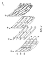
- Figure 1 illustrates one exemplary embodiment of the components in a keypad assembly
- Figure 2 illustrates an exemplary embodiment of the keypad assembly
- Figure 3 illustrates an exemplary housing
- Figure 4 illustrates a backside view of the keypad coupled with the housing
- Figure 5 illustrates a connection of the housing with the keypad
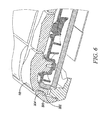
- Figure 6 illustrates a locking of the edge keys.
- the keypad may be for an electronic device, such as a smartphone, laptop, or other handheld device.
- the housing of the electronic device is coupled with the keypad such that the keys extend to the edges of the device.
- the edge keys are secured against being removed from the keypad despite being at the edge of the housing and edge of the device.
- the edge keys may include a hook or locking mechanism coupled with the housing to prevent uprooting of the edge keys. Another set of hooks or locking mechanisms may connect the housing with the keypad to prevent bulging of the housing and to limit lateral movement of the keys or the keypad with respect to the housing.
- Electronic devices may include keys or buttons for receiving inputs.
- a keypad may include one or more keys on the device.
- Exemplary electronic devices with keys or a keypad may include, but are not limited to, a telephone, cellular phone, smartphone, personal digital assistant ("PDA"), laptop computer, netbook computer, tablet, pager, or any other device with a keyboard.
- PDA personal digital assistant
- the keypad structure and connecters that are described herein may be applicable to any device with keys or a keypad.
- the keypad of an electronic device may include various buttons or inputs.
- Exemplary keypads include QWERTY, AZERTY, and Dvorak keyboard arrangements. There may be a complete alphanumeric keypad with buttons for each letter. Alternatively, multiple letters may be assigned to each button or the keypad may be a telephone-type keypad.
- Other exemplary buttons or inputs include select/enter, cancel, talk, play, stop, fast forward, rewind, next, previous buttons.
- the device may have a number of navigation control buttons that may provide a number of functions such as a send or end key for a mobile telephone application of the device, a menu key, an escape key, etc.
- the device may include one or more circuit boards (not shown), a microprocessor, a memory, a battery, an antennae, etc., any of which may be coupled with the keypad and may form part of the keypad assembly.
- the keypad assembly may include multiple components including a keypad portion with keys, a light guide, an electrical switch assembly or printed circuit board (PCB) and a casing.
- the electrical switch assembly may include a number of dome switches, such as one dome switch for each key in the keypad portion.
- the keypad portion may be a film-in-plastic ("FIP") or an in-mould-decoration ("IMD") keypad having a number of keys.
- the housing or casing may be a bezel frame having a single opening for the keypad portion. Alternatively, the housing may include a separate hole for each of the keys.
- the keys may each have a contact surface on the front side where a user may push down on a particular key and an actuator post connected to the back side of each key, such that when the user depresses the contact surface of a key, the actuator post of the respective key travels in the direction of actuation and contacts a respective dome switch thereby closing an electrical contact of the associated electrical dome switch allowing detection of the key depression.
- Figure 1 illustrates one exemplary embodiment of components in a keypad assembly 100.
- the keypad assembly 100 illustrated in Figure 1 may be for a smartphone or a handheld electronic device.
- the keypad assembly 100 shown in Figure 1 includes keypad keys 102 (also referred to as the keypad portion 102) coupled with a lightguide 108 using frets 104 and a mask sheet 106.
- keypad keys 102 also referred to as the keypad portion 102
- frets 104 also referred to as the keypad portion 102
- a mask sheet 106 a mask sheet 106.
- the phrase "coupled with” is defined to mean directly connected to or indirectly connected through one or more intermediate components. Such intermediate components may include both hardware and software based components. Variations in the arrangement and type of the components may be made without departing from the spirit or scope of the claims as set forth herein. Additional, different or fewer components may be provided.
- the keypad assembly 100 may include a keypad portion, keypad layer, a lightguide layer, a dome layer, a flexible printed circuit ("FPC") or printed circuit board layer (“PCB”), and/or a piezoelectric layer.
- the keypad layer may be a flat sheet which incorporates a film style keypad sheet.
- the film style keypad sheet may form an input keypad surface.
- the film style keypad sheet may be a continuous layer of flexible sheet material.
- the keypad assembly 100 may include a dome layer with an array of domes corresponding with the keys. Pressing of the keys may result in an actuation of a corresponding dome which is detected by the device.
- An FPC or PCB circuit layer may underlie the dome layer and include an array of contact pads or electrical switches that correspond to the keys and that detect the actuation of those keys.
- a circuit board may be an additional component of the keypad assembly 100, or may be part of one of the components, such as the lightguide 108 which may include or be coupled with the PCB.
- the keypad keys 102 may also be referred to as the keypad portion. Alternatively, the keypad keys 102 may be referred to as the keypad throughout this description for simplicity.
- the keypad keys 102 include a number of keys for physical actuation where each of the keys may have an actuator post attached to a back side of the key.
- the keypad keys 102 include two columns of edge keys 110 on opposite edges of the electronic device.
- the edge keys 110 are the keys located along opposite side edges of the electronic device.
- the embodiment shown illustrates that the edge keys 102 are curved, and specifically that the outermost edges of the edge keys are curved.
- the edge key 102 curvature creates a rounded edge of the device as the keys are curved downwards towards the outside edge of the device (as shown in Figures 2 and 5 , for example).
- the edge keys 102 may not be curved and may be straight across to the edge of the device, or the edge keys 102 may include a different curvature than shown in this embodiment.
- the keypad frets 104 are coupled with the keypad keys 102 for maintaining the key arrangement; however it is appreciated that other embodiments without the frets may be possible.
- the keypad mask sheet 106 provides openings for key actuations to be sensed.
- the lightguide plate 108 may include or be coupled with a backlight for directing light to the keypad keys 102.
- the lightguide plate 108 may be a flexible flat film layer.
- the lightguide plate 108 may include micro-optical features which may help to disperse light through the lightguide plate 108.
- the lightguide plate 108 may allow the keypad to be backlit.
- the keypad assembly 100 may contain numbers, letters, or designs which may be seen more clearly when backlit. However, the lightguide plate 108 may be omitted and the keypad assembly may not be backlit or another means of lighting may be present.
- the lightguiding feature may be incorporated into another layer or another component.
- the lightguide plate 108 may include a receiving portion for each of the keys from the keypad. There may be holes for each of the keys to connect with the keys.
- the lightguide plate 108 top portion is rubber and receives the keys, which are glued into the corresponding portions of the plate. There may be additional components that are part of the keypad assembly into which the keys are coupled.
- Figure 2 illustrates an exemplary embodiment of the keypad assembly.
- Figure 2 illustrates the keypad assembly 100 in an assembled form.
- the cross-sections shown in Figure 2 correspond to Figure 5 and Figure 6 as labeled.
- the keypad assembly 100 is combined with an exterior housing or casing.
- FIG 2 illustrates three edge keys 110.
- Each of the edge keys 110 includes a protruding portion 202 that is coupled with or part of the edge key for preventing the edge keys 110 from being removed or pried up from the keypad as further discussed with respect to Figure 6 .
- the protruding portion 202 may be referred to as a hook or locking mechanism. As described below, the protruding portion 202 is held by the housing or casing to prevent the key from being pried away from the keypad assembly 100.
- FIG. 2 Also shown in Figure 2 are four hooks or lockings 204 that are part of the keypad assembly 100.
- the lockings 204 connect or interlock with corresponding hooks or lockings in the front housing as further discussed with respect to Figure 5 .
- the interlocking of the lockings 204 of the keypad assembly 100 with the housing may prevent bulging by limiting or preventing lateral movement between the keypad assembly 100 and the housing.
- Each of the protruding portions 202 may be located between the lockings 204, so the protruding portions 202 and the lockings 204 are spaced between one another on the edge of the keypad assembly 100.
- Figure 3 illustrates an exemplary housing 300.
- the housing 300 may also be referred to as a casing or cover.
- the housing 300 may be made of a plastic, composite, or metal.
- the housing 300 is the front cover for the electronic device and is coupled with the keypad assembly 100.
- Figure 3 illustrates a backside or underneath view of the front housing 300. In other words, the back of the electronic device is shown face up in Figure 3 and the keypad would be on the front of the electronic device and facing down in Figure 3 .
- the housing 300 includes lockings 302 that interlock with the lockings 204 from the keypad assembly 100 shown in Figure 2 .
- the housing lockings 302 lock with the keypad lockings 204 to prevent lateral movement as illustrated in Figure 5 .
- Between respective lockings 302 in the housing 300 are gaps where the keypad protruding portions 202 from the keypad assembly can be located against or underneath a hook 304 when the housing 300 is attached to the keypad assembly.
- the hook 304 may be an overhang or a gap that is filled by the protruding portion 202 from the edge keys 110 to prevent the edge keys 110 from being removed vertically.
- the protruding portions 202 of the edge keys disposed within the gaps against the hooks 304 of the housing are illustrated in Figure 6 .
- Figure 4 illustrates a backside view of the keypad coupled with the housing.
- Figure 4 illustrates the front housing 300 coupled with the keypad assembly 100 where the backside or underside of the keypad assembly 100 (e.g. the lightguide 108 or back component of the keypad assembly) is visible.
- the keys of the keypad assembly 100 are on the other side of the electronic device and are not seen in the underneath view of Figure 4 .
- a circuit board or PCB layer (not shown) of the electronic device may be located at the back of the keypad assembly in Figure 4 .
- the keypad assembly is coupled with the housing 300 by the keyboard lockings 204 which are connected with the respective housing lockings 302 in the housing 300.
- the housing lockings 302 are not visible in the backside view of Figure 4 .
- the protruding portions 202 from each of the edge keys 110 are connected with corresponding hooks 302 in the housing.
- the hashed cross-sections shown in Figure 4 correspond to Figure 5 and Figure 6 as labeled. Compared with the cross-sections shown in Figure 2 and the perspectives of Figures 5 and 6 , the cross-sections shown in Figure 4 are flipped because Figure 4 illustrates a back side or under side view of the device while Figure 2 illustrates a top view of the keypad assembly.
- Figure 5 illustrates a connection of the housing 300 with the keypad assembly.
- the lightguide 108 and the mask sheet 106 are also illustrated as part of the keypad assembly in Figure 5 .
- the keypad assembly may include components other than the fret 104, the mask sheet 106, and the lightguide 108.
- the keypad assembly 100 includes an end portion that includes the locking 204.
- the end portion may be an extension of the keypad assembly.
- the housing 300 includes the housing locking 302 that matches with or interlocks with the keypad locking 204.
- the interlocking of the housing locking 302 and the keypad locking 204 may prevent the housing 300 from bulging or widening up.
- the interlocking may keep the keypad assembly in a planar or flat orientation, such that the keypad does not bulge relative to the front plane of the device.
- the interlocking may prevent lateral movement between the housing 300 and the keypad assembly by keeping the housing 300 pulled in towards the center of the electronic device.
- the interlocking may maintain the shape of the housing 300 with respect to the keypad assembly 100.
- the interlocking minimizes the space between the housing 300 and the keypad assembly so that the key protruding portions 202 can prevent the keys from being pulled or pried from the device as further discussed with respect to Figure 6 .
- the locking 204 may be a part of or coupled with the keypad assembly 100 for interlocking with the housing 300.
- the locking 204 may be plastic molding that is attached to the keypad assembly or a part of one of the components of the keypad assembly.
- the lightguide 108 or other components in the keypad assembly may be coupled with or may include the locking 204.
- the lightguide 108 may be made of plastic that is extended outwards to include a plastic locking 204 on either edge.
- FIG. 6 illustrates a locking for the edge keys 110.
- the edge keys 110 of the keypad assembly include the protruding portion 202 that prevents removal of the edge keys 110 and allows for the edge keys 110 to be disposed up to the edge of the device.
- the edge keys 110 may be disposed over the housing 300 such that the housing 300 is barely visible or not visible in a top view of the device.
- the housing 300 may include a gap area that is filled by the protruding portion 202 of the edge key 110.
- the gap area in the housing 300 includes a hook 304 above the gap that prevents the protruding portion 202 from being lifted above that hook 304.
- the edge key 110 may still be pushed downward for actuation, but the hook 304 limits upward movements of the edge key 110.
- the protruding portion 202 may be rounded and extends in a lateral direction away from the center of the device such that the hooks 304 of the housing 300 extend over the protruding portion 202 to prevent vertical movement of the edge key 110.
- the protruding portion 202 may be an extension of the edge keys 110 and made of the same material as the edge keys.
- the edge keys 110 may be a plastic or rubber material that includes a corresponding plastic or rubber protruding portion 202 for each edge key 110.
- the protruding portion 202 may be a separate piece that is coupled with the edge key 110.
- the housing 300 is maintained against or close to the protruding portion 202 of the edge key 110. This prevents a gap from forming between the housing and the keypad assembly that may otherwise allow the edge key 110 to be removed if not secured with the protruding portion 202 against the housing hook 304. Because lateral movement between the housing and the keypad assembly is prevented or reduced, the protruding portion 202 prevents vertical movement of the edge key 110 since the protruding portion 202 cannot fit past the hook 304 of the housing.
- the combination of the disclosed protruding portion and housing hook, as well as the key and housing lockings secure the keypad to the device.
- This securing mechanism prevents bulging and makes it difficult for a user to pry keys from the keypad.
- this mechanism reduces the distance between component, including the distance between housing and keyboard, which may prevent dirt and/or moisture from entering the assembly.
- the curvature of the edge keys provides a smooth outer surface that fits comfortably into a user's hand.
Landscapes
- Engineering & Computer Science (AREA)
- Signal Processing (AREA)
- Telephone Set Structure (AREA)
- Push-Button Switches (AREA)
Priority Applications (3)
| Application Number | Priority Date | Filing Date | Title |
|---|---|---|---|
| EP11183008.9A EP2575330B1 (de) | 2011-09-27 | 2011-09-27 | System zur Sicherung einer Tastatur auf einem Gehäuse |
| EP12170596.6A EP2579557B1 (de) | 2011-09-27 | 2011-09-27 | System zur Sicherung einer Tastatur auf einem Gehäuse |
| CA2786349A CA2786349C (en) | 2011-09-27 | 2012-08-16 | System for securing a keypad to a housing |
Applications Claiming Priority (1)
| Application Number | Priority Date | Filing Date | Title |
|---|---|---|---|
| EP11183008.9A EP2575330B1 (de) | 2011-09-27 | 2011-09-27 | System zur Sicherung einer Tastatur auf einem Gehäuse |
Related Child Applications (3)
| Application Number | Title | Priority Date | Filing Date |
|---|---|---|---|
| EP12170596.6A Division-Into EP2579557B1 (de) | 2011-09-27 | 2011-09-27 | System zur Sicherung einer Tastatur auf einem Gehäuse |
| EP12170596.6A Division EP2579557B1 (de) | 2011-09-27 | 2011-09-27 | System zur Sicherung einer Tastatur auf einem Gehäuse |
| EP12170596.6 Division-Into | 2012-06-01 |
Publications (2)
| Publication Number | Publication Date |
|---|---|
| EP2575330A1 true EP2575330A1 (de) | 2013-04-03 |
| EP2575330B1 EP2575330B1 (de) | 2018-08-22 |
Family
ID=44763918
Family Applications (2)
| Application Number | Title | Priority Date | Filing Date |
|---|---|---|---|
| EP12170596.6A Active EP2579557B1 (de) | 2011-09-27 | 2011-09-27 | System zur Sicherung einer Tastatur auf einem Gehäuse |
| EP11183008.9A Active EP2575330B1 (de) | 2011-09-27 | 2011-09-27 | System zur Sicherung einer Tastatur auf einem Gehäuse |
Family Applications Before (1)
| Application Number | Title | Priority Date | Filing Date |
|---|---|---|---|
| EP12170596.6A Active EP2579557B1 (de) | 2011-09-27 | 2011-09-27 | System zur Sicherung einer Tastatur auf einem Gehäuse |
Country Status (2)
| Country | Link |
|---|---|
| EP (2) | EP2579557B1 (de) |
| CA (1) | CA2786349C (de) |
Families Citing this family (1)
| Publication number | Priority date | Publication date | Assignee | Title |
|---|---|---|---|---|
| CN114823199B (zh) * | 2021-01-29 | 2026-01-02 | Oppo广东移动通信有限公司 | 电子装置及其按键 |
Citations (3)
| Publication number | Priority date | Publication date | Assignee | Title |
|---|---|---|---|---|
| US20060142074A1 (en) * | 2004-12-29 | 2006-06-29 | Jussi Impio | Mobile communication unit with display area widening mechanism |
| EP2106102A2 (de) * | 2008-03-27 | 2009-09-30 | LG - Nortel Co., Ltd. | Kommunikationsendgerät mit Gehäuse mit damit verbundenen Tastenknöpfen |
| DE102008038567A1 (de) * | 2008-08-20 | 2010-02-25 | Leopold Kostal Gmbh & Co. Kg | Anordnung von miteinander verbundenen Betätigungselementen für Drucktaster oder Druckschalter |
Family Cites Families (1)
| Publication number | Priority date | Publication date | Assignee | Title |
|---|---|---|---|---|
| CN101925971A (zh) * | 2008-01-24 | 2010-12-22 | 松下电器产业株式会社 | 按键开关和电子设备 |
-
2011
- 2011-09-27 EP EP12170596.6A patent/EP2579557B1/de active Active
- 2011-09-27 EP EP11183008.9A patent/EP2575330B1/de active Active
-
2012
- 2012-08-16 CA CA2786349A patent/CA2786349C/en active Active
Patent Citations (3)
| Publication number | Priority date | Publication date | Assignee | Title |
|---|---|---|---|---|
| US20060142074A1 (en) * | 2004-12-29 | 2006-06-29 | Jussi Impio | Mobile communication unit with display area widening mechanism |
| EP2106102A2 (de) * | 2008-03-27 | 2009-09-30 | LG - Nortel Co., Ltd. | Kommunikationsendgerät mit Gehäuse mit damit verbundenen Tastenknöpfen |
| DE102008038567A1 (de) * | 2008-08-20 | 2010-02-25 | Leopold Kostal Gmbh & Co. Kg | Anordnung von miteinander verbundenen Betätigungselementen für Drucktaster oder Druckschalter |
Also Published As
| Publication number | Publication date |
|---|---|
| CA2786349C (en) | 2018-03-13 |
| EP2579557A1 (de) | 2013-04-10 |
| CA2786349A1 (en) | 2013-03-27 |
| EP2575330B1 (de) | 2018-08-22 |
| EP2579557B1 (de) | 2018-02-07 |
Similar Documents
| Publication | Publication Date | Title |
|---|---|---|
| US6891529B2 (en) | Keyboard assembly for a mobile device | |
| JP2002341995A (ja) | 携帯用通信機 | |
| US8760406B2 (en) | Edge to edge qwerty keypad for a handheld device | |
| US20110285630A1 (en) | Electronic apparatus | |
| US20110074608A1 (en) | Button-key device and portable terminal apparatus | |
| US9641920B1 (en) | Support structures for computing devices | |
| US20080119247A1 (en) | Information processing terminal | |
| US7067757B1 (en) | Multi-tier keypad assembly | |
| EP2579557B1 (de) | System zur Sicherung einer Tastatur auf einem Gehäuse | |
| US8665220B2 (en) | System for securing a keypad to a housing | |
| EP1727335B1 (de) | Anzeigeeinrichtung und mobiles Endgerät mit entsprechender Einrichtung | |
| CA2756992C (en) | Keyboard | |
| JP4743701B2 (ja) | 携帯電子機器 | |
| EP2469809B1 (de) | Mobile Vorrichtung | |
| US20130141337A1 (en) | Keypad fastening apparatus | |
| EP2518593B1 (de) | Tastatur mit einer gebogenen Form | |
| CN101303611A (zh) | 具有键盘模块的电子装置 | |
| US20110233039A1 (en) | Mobile terminal device and keypad | |
| CN101174512A (zh) | 薄型键盘 | |
| EP2487880B1 (de) | Elektronisches Mobilgerät mit einer Tastaturanordnung mit Overlayfolie | |
| KR200408473Y1 (ko) | 개선된 키패드부를 구비하는 이동통신 단말기 | |
| JP4930841B2 (ja) | 電子機器 | |
| JP2007207686A (ja) | キーラバー、キー操作部及び電子機器 | |
| JP5435079B2 (ja) | 電子機器 | |
| KR100696141B1 (ko) | 휴대용 단말기의 키버튼 어셈블리 |
Legal Events
| Date | Code | Title | Description |
|---|---|---|---|
| PUAI | Public reference made under article 153(3) epc to a published international application that has entered the european phase |
Free format text: ORIGINAL CODE: 0009012 |
|
| 17P | Request for examination filed |
Effective date: 20110927 |
|
| AK | Designated contracting states |
Kind code of ref document: A1 Designated state(s): AL AT BE BG CH CY CZ DE DK EE ES FI FR GB GR HR HU IE IS IT LI LT LU LV MC MK MT NL NO PL PT RO RS SE SI SK SM TR |
|
| AX | Request for extension of the european patent |
Extension state: BA ME |
|
| RAP1 | Party data changed (applicant data changed or rights of an application transferred) |
Owner name: BLACKBERRY LIMITED |
|
| RAP1 | Party data changed (applicant data changed or rights of an application transferred) |
Owner name: BLACKBERRY LIMITED |
|
| 17Q | First examination report despatched |
Effective date: 20151124 |
|
| GRAP | Despatch of communication of intention to grant a patent |
Free format text: ORIGINAL CODE: EPIDOSNIGR1 |
|
| INTG | Intention to grant announced |
Effective date: 20180309 |
|
| GRAS | Grant fee paid |
Free format text: ORIGINAL CODE: EPIDOSNIGR3 |
|
| GRAA | (expected) grant |
Free format text: ORIGINAL CODE: 0009210 |
|
| AK | Designated contracting states |
Kind code of ref document: B1 Designated state(s): AL AT BE BG CH CY CZ DE DK EE ES FI FR GB GR HR HU IE IS IT LI LT LU LV MC MK MT NL NO PL PT RO RS SE SI SK SM TR |
|
| REG | Reference to a national code |
Ref country code: GB Ref legal event code: FG4D |
|
| REG | Reference to a national code |
Ref country code: CH Ref legal event code: EP |
|
| REG | Reference to a national code |
Ref country code: AT Ref legal event code: REF Ref document number: 1033821 Country of ref document: AT Kind code of ref document: T Effective date: 20180915 |
|
| REG | Reference to a national code |
Ref country code: IE Ref legal event code: FG4D |
|
| REG | Reference to a national code |
Ref country code: DE Ref legal event code: R096 Ref document number: 602011051243 Country of ref document: DE |
|
| REG | Reference to a national code |
Ref country code: FR Ref legal event code: PLFP Year of fee payment: 8 |
|
| REG | Reference to a national code |
Ref country code: NL Ref legal event code: FP |
|
| REG | Reference to a national code |
Ref country code: LT Ref legal event code: MG4D |
|
| PG25 | Lapsed in a contracting state [announced via postgrant information from national office to epo] |
Ref country code: RS Free format text: LAPSE BECAUSE OF FAILURE TO SUBMIT A TRANSLATION OF THE DESCRIPTION OR TO PAY THE FEE WITHIN THE PRESCRIBED TIME-LIMIT Effective date: 20180822 Ref country code: FI Free format text: LAPSE BECAUSE OF FAILURE TO SUBMIT A TRANSLATION OF THE DESCRIPTION OR TO PAY THE FEE WITHIN THE PRESCRIBED TIME-LIMIT Effective date: 20180822 Ref country code: NO Free format text: LAPSE BECAUSE OF FAILURE TO SUBMIT A TRANSLATION OF THE DESCRIPTION OR TO PAY THE FEE WITHIN THE PRESCRIBED TIME-LIMIT Effective date: 20181122 Ref country code: SE Free format text: LAPSE BECAUSE OF FAILURE TO SUBMIT A TRANSLATION OF THE DESCRIPTION OR TO PAY THE FEE WITHIN THE PRESCRIBED TIME-LIMIT Effective date: 20180822 Ref country code: BG Free format text: LAPSE BECAUSE OF FAILURE TO SUBMIT A TRANSLATION OF THE DESCRIPTION OR TO PAY THE FEE WITHIN THE PRESCRIBED TIME-LIMIT Effective date: 20181122 Ref country code: GR Free format text: LAPSE BECAUSE OF FAILURE TO SUBMIT A TRANSLATION OF THE DESCRIPTION OR TO PAY THE FEE WITHIN THE PRESCRIBED TIME-LIMIT Effective date: 20181123 Ref country code: IS Free format text: LAPSE BECAUSE OF FAILURE TO SUBMIT A TRANSLATION OF THE DESCRIPTION OR TO PAY THE FEE WITHIN THE PRESCRIBED TIME-LIMIT Effective date: 20181222 Ref country code: LT Free format text: LAPSE BECAUSE OF FAILURE TO SUBMIT A TRANSLATION OF THE DESCRIPTION OR TO PAY THE FEE WITHIN THE PRESCRIBED TIME-LIMIT Effective date: 20180822 |
|
| REG | Reference to a national code |
Ref country code: AT Ref legal event code: MK05 Ref document number: 1033821 Country of ref document: AT Kind code of ref document: T Effective date: 20180822 |
|
| PG25 | Lapsed in a contracting state [announced via postgrant information from national office to epo] |
Ref country code: HR Free format text: LAPSE BECAUSE OF FAILURE TO SUBMIT A TRANSLATION OF THE DESCRIPTION OR TO PAY THE FEE WITHIN THE PRESCRIBED TIME-LIMIT Effective date: 20180822 Ref country code: LV Free format text: LAPSE BECAUSE OF FAILURE TO SUBMIT A TRANSLATION OF THE DESCRIPTION OR TO PAY THE FEE WITHIN THE PRESCRIBED TIME-LIMIT Effective date: 20180822 Ref country code: AL Free format text: LAPSE BECAUSE OF FAILURE TO SUBMIT A TRANSLATION OF THE DESCRIPTION OR TO PAY THE FEE WITHIN THE PRESCRIBED TIME-LIMIT Effective date: 20180822 |
|
| PG25 | Lapsed in a contracting state [announced via postgrant information from national office to epo] |
Ref country code: AT Free format text: LAPSE BECAUSE OF FAILURE TO SUBMIT A TRANSLATION OF THE DESCRIPTION OR TO PAY THE FEE WITHIN THE PRESCRIBED TIME-LIMIT Effective date: 20180822 Ref country code: CZ Free format text: LAPSE BECAUSE OF FAILURE TO SUBMIT A TRANSLATION OF THE DESCRIPTION OR TO PAY THE FEE WITHIN THE PRESCRIBED TIME-LIMIT Effective date: 20180822 Ref country code: PL Free format text: LAPSE BECAUSE OF FAILURE TO SUBMIT A TRANSLATION OF THE DESCRIPTION OR TO PAY THE FEE WITHIN THE PRESCRIBED TIME-LIMIT Effective date: 20180822 Ref country code: RO Free format text: LAPSE BECAUSE OF FAILURE TO SUBMIT A TRANSLATION OF THE DESCRIPTION OR TO PAY THE FEE WITHIN THE PRESCRIBED TIME-LIMIT Effective date: 20180822 Ref country code: ES Free format text: LAPSE BECAUSE OF FAILURE TO SUBMIT A TRANSLATION OF THE DESCRIPTION OR TO PAY THE FEE WITHIN THE PRESCRIBED TIME-LIMIT Effective date: 20180822 Ref country code: EE Free format text: LAPSE BECAUSE OF FAILURE TO SUBMIT A TRANSLATION OF THE DESCRIPTION OR TO PAY THE FEE WITHIN THE PRESCRIBED TIME-LIMIT Effective date: 20180822 Ref country code: IT Free format text: LAPSE BECAUSE OF FAILURE TO SUBMIT A TRANSLATION OF THE DESCRIPTION OR TO PAY THE FEE WITHIN THE PRESCRIBED TIME-LIMIT Effective date: 20180822 |
|
| REG | Reference to a national code |
Ref country code: CH Ref legal event code: PL |
|
| REG | Reference to a national code |
Ref country code: DE Ref legal event code: R097 Ref document number: 602011051243 Country of ref document: DE |
|
| PG25 | Lapsed in a contracting state [announced via postgrant information from national office to epo] |
Ref country code: DK Free format text: LAPSE BECAUSE OF FAILURE TO SUBMIT A TRANSLATION OF THE DESCRIPTION OR TO PAY THE FEE WITHIN THE PRESCRIBED TIME-LIMIT Effective date: 20180822 Ref country code: SM Free format text: LAPSE BECAUSE OF FAILURE TO SUBMIT A TRANSLATION OF THE DESCRIPTION OR TO PAY THE FEE WITHIN THE PRESCRIBED TIME-LIMIT Effective date: 20180822 Ref country code: SK Free format text: LAPSE BECAUSE OF FAILURE TO SUBMIT A TRANSLATION OF THE DESCRIPTION OR TO PAY THE FEE WITHIN THE PRESCRIBED TIME-LIMIT Effective date: 20180822 |
|
| REG | Reference to a national code |
Ref country code: BE Ref legal event code: MM Effective date: 20180930 |
|
| REG | Reference to a national code |
Ref country code: IE Ref legal event code: MM4A |
|
| PG25 | Lapsed in a contracting state [announced via postgrant information from national office to epo] |
Ref country code: LU Free format text: LAPSE BECAUSE OF NON-PAYMENT OF DUE FEES Effective date: 20180927 Ref country code: MC Free format text: LAPSE BECAUSE OF FAILURE TO SUBMIT A TRANSLATION OF THE DESCRIPTION OR TO PAY THE FEE WITHIN THE PRESCRIBED TIME-LIMIT Effective date: 20180822 |
|
| PLBE | No opposition filed within time limit |
Free format text: ORIGINAL CODE: 0009261 |
|
| STAA | Information on the status of an ep patent application or granted ep patent |
Free format text: STATUS: NO OPPOSITION FILED WITHIN TIME LIMIT |
|
| 26N | No opposition filed |
Effective date: 20190523 |
|
| PG25 | Lapsed in a contracting state [announced via postgrant information from national office to epo] |
Ref country code: IE Free format text: LAPSE BECAUSE OF NON-PAYMENT OF DUE FEES Effective date: 20180927 |
|
| PG25 | Lapsed in a contracting state [announced via postgrant information from national office to epo] |
Ref country code: LI Free format text: LAPSE BECAUSE OF NON-PAYMENT OF DUE FEES Effective date: 20180930 Ref country code: SI Free format text: LAPSE BECAUSE OF FAILURE TO SUBMIT A TRANSLATION OF THE DESCRIPTION OR TO PAY THE FEE WITHIN THE PRESCRIBED TIME-LIMIT Effective date: 20180822 Ref country code: CH Free format text: LAPSE BECAUSE OF NON-PAYMENT OF DUE FEES Effective date: 20180930 Ref country code: BE Free format text: LAPSE BECAUSE OF NON-PAYMENT OF DUE FEES Effective date: 20180930 |
|
| PG25 | Lapsed in a contracting state [announced via postgrant information from national office to epo] |
Ref country code: MT Free format text: LAPSE BECAUSE OF NON-PAYMENT OF DUE FEES Effective date: 20180927 |
|
| PG25 | Lapsed in a contracting state [announced via postgrant information from national office to epo] |
Ref country code: TR Free format text: LAPSE BECAUSE OF FAILURE TO SUBMIT A TRANSLATION OF THE DESCRIPTION OR TO PAY THE FEE WITHIN THE PRESCRIBED TIME-LIMIT Effective date: 20180822 |
|
| PG25 | Lapsed in a contracting state [announced via postgrant information from national office to epo] |
Ref country code: PT Free format text: LAPSE BECAUSE OF FAILURE TO SUBMIT A TRANSLATION OF THE DESCRIPTION OR TO PAY THE FEE WITHIN THE PRESCRIBED TIME-LIMIT Effective date: 20180822 Ref country code: HU Free format text: LAPSE BECAUSE OF FAILURE TO SUBMIT A TRANSLATION OF THE DESCRIPTION OR TO PAY THE FEE WITHIN THE PRESCRIBED TIME-LIMIT; INVALID AB INITIO Effective date: 20110927 |
|
| PG25 | Lapsed in a contracting state [announced via postgrant information from national office to epo] |
Ref country code: CY Free format text: LAPSE BECAUSE OF FAILURE TO SUBMIT A TRANSLATION OF THE DESCRIPTION OR TO PAY THE FEE WITHIN THE PRESCRIBED TIME-LIMIT Effective date: 20180822 Ref country code: MK Free format text: LAPSE BECAUSE OF NON-PAYMENT OF DUE FEES Effective date: 20180822 |
|
| REG | Reference to a national code |
Ref country code: DE Ref legal event code: R082 Ref document number: 602011051243 Country of ref document: DE Ref country code: DE Ref legal event code: R081 Ref document number: 602011051243 Country of ref document: DE Owner name: MALIKIE INNOVATIONS LTD., IE Free format text: FORMER OWNER: BLACKBERRY LIMITED, WATERLOO, ONTARIO, CA |
|
| REG | Reference to a national code |
Ref country code: GB Ref legal event code: 732E Free format text: REGISTERED BETWEEN 20240620 AND 20240627 |
|
| PGFP | Annual fee paid to national office [announced via postgrant information from national office to epo] |
Ref country code: DE Payment date: 20250926 Year of fee payment: 15 |
|
| PGFP | Annual fee paid to national office [announced via postgrant information from national office to epo] |
Ref country code: NL Payment date: 20250925 Year of fee payment: 15 |
|
| PGFP | Annual fee paid to national office [announced via postgrant information from national office to epo] |
Ref country code: GB Payment date: 20250923 Year of fee payment: 15 |
|
| PGFP | Annual fee paid to national office [announced via postgrant information from national office to epo] |
Ref country code: FR Payment date: 20250925 Year of fee payment: 15 |