EP2575236B1 - Stromspeicherungssteuerungsvorrichtung und Stromspeicherungssteuerungsverfahren - Google Patents
Stromspeicherungssteuerungsvorrichtung und Stromspeicherungssteuerungsverfahren Download PDFInfo
- Publication number
- EP2575236B1 EP2575236B1 EP12184810.5A EP12184810A EP2575236B1 EP 2575236 B1 EP2575236 B1 EP 2575236B1 EP 12184810 A EP12184810 A EP 12184810A EP 2575236 B1 EP2575236 B1 EP 2575236B1
- Authority
- EP
- European Patent Office
- Prior art keywords
- consumption
- power
- information
- power storage
- example embodiment
- Prior art date
- Legal status (The legal status is an assumption and is not a legal conclusion. Google has not performed a legal analysis and makes no representation as to the accuracy of the status listed.)
- Not-in-force
Links
Images


Classifications
-
- H—ELECTRICITY
- H02—GENERATION; CONVERSION OR DISTRIBUTION OF ELECTRIC POWER
- H02J—ELECTRIC POWER NETWORKS; CIRCUIT ARRANGEMENTS OR SYSTEMS FOR SUPPLYING OR DISTRIBUTING ELECTRIC POWER; SYSTEMS FOR STORING ELECTRIC ENERGY
- H02J7/00—Circuit arrangements for charging or discharging batteries or for supplying loads from batteries
- H02J7/34—Parallel operation in networks using both storage and other DC sources, e.g. providing buffering
- H02J7/35—Parallel operation in networks using both storage and other DC sources, e.g. providing buffering with light sensitive cells
Definitions
- the present technology relates to a power storage control apparatus and a power storage control method.
- Japanese Unexamined Patent Application Publication No. 2010-213507 discloses a power storage control method of efficiently storing the power generated from the natural energy on a battery by the use of weather information.
- a consumption apparatus such as an electric vehicle, an electric scooter, or an electric bicycle
- the power storage control of the apparatus may not be in operation.
- efficient power storage control is performed based on the power consumption of an apparatus connected to the system, for example, the power unconsumed by the apparatus is sold as surplus power to a power company or the like.
- a consumption apparatus is connected to the system, it can be considered that unexpected power consumption in the power storage control may occur (for example, charging of a battery), and thus there is a possibility that the consumed power is not supplemented with the power stored in the secondary cell. That is, with the power storage control, the natural energy is not efficiently used.
- An embodiment of the present technology is directed to a power storage control apparatus including: a connection monitoring unit that monitors a connection state between a power feeding terminal configured to receive power from a power generation apparatus generating power using natural energy or a power storage apparatus storing the power generated by the power generation apparatus and a consumption apparatus that mounts a battery and operates using power stored in the battery; and a power storage control unit that adjusts an amount of power to be stored in the power storage apparatus.
- the power storage control unit adjusts the amount of power to be stored in the power storage apparatus in consideration of an amount of power to be consumed by the separated consumption apparatus when the consumption apparatus connected to the power feeding terminal is separated from the power feeding terminal.
- Another embodiment of the present technology is directed to a power storage control method including: monitoring a connection state between a power feeding terminal configured to receive power from a power generation apparatus generating power using natural energy or a power storage apparatus storing the power generated by the power generation apparatus and a consumption apparatus that mounts a battery and operates using power stored in the battery; and adjusting an amount of power to be stored in the power storage apparatus.
- the amount of power to be stored in the power storage apparatus is adjusted in consideration of an amount of power to be consumed by the separated consumption apparatus when the consumption apparatus connected to the power feeding terminal is separated from the power feeding terminal.
- a power storage control apparatus includes a power storage control unit configured to: (a) determine a connection state of a consumption apparatus with a power supply; (b) determine an expected amount of power usage by the consumption apparatus in a connected state; and (c) adjusting a target value of power storage for a power storage apparatus based on a change in connection state and the expected amount of power usage by the consumption apparatus.
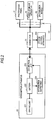
- Fig. 1 is a diagram illustrating an example of the configuration of the power system.
- the power system includes a photovoltaic panel 11, a DC/DC converter 12, a power bus 13, and a power storage apparatus 14.
- the power system further includes a distribution board 16, a power bus 17, an AC/DC converter 18, a system linkage inverter 19, a household consumption apparatus 20, a connector 21, and a system control apparatus 100.
- the distribution board 16 is supplied with system power from a power company 15.
- a consumption apparatus 22 detachably mounted on the power system can be connected to the connector 21.
- a connector 21 may employ any suitable connection type for power transfer between the connector 21 and the consumption apparatus 22, including but not limited to, a direct connection (e.g., a wired plug-in connection), a wireless connection (e.g., a resonant coupling).
- the connector 21 does not require any direct connection or mounting of the consumption apparatus 22 with the connector 21.
- the photovoltaic panel 11 is an example of power generation equipment that generates power from natural energy. Another power generation equipment such as wind power generation equipment, hydraulic power generation equipment, geothermal power generation equipment, or biomass power generation equipment can be used as the power generation equipment. Here, to facilitate the description, it is assumed that the photovoltaic panel 11 is used.
- the power generated by the photovoltaic panel 11 is supplied to the power bus 13 via the DC/DC converter 12.
- the power supplied to the power bus 13 is accumulated in the power storage apparatus 14, is supplied to the consumption apparatus 22 connected to the connector 21, or is supplied to the power bus 17 via the system linkage inverter 19.
- the power supplied to the power bus 17 is consumed by the household consumption apparatus 20 connected to the power bus 17 or is sold to the power company 15 via the distribution board 16.
- a meter that measures the amount of input or output power is mounted on the distribution board 16.
- System power supplied from the power company 15 is supplied to the power bus 17 via the distribution board 16.
- the system power supplied to the power bus 17 is consumed by the household consumption apparatus 20 connected to the power bus 17 or is supplied to the power bus 13 via the AC/DC converter 18. Further, the system power supplied to the power bus 13 can be stored in the power storage apparatus 14 or is supplied to the consumption apparatus 22 connected to the connector 21.
- the management of the power in the power system is performed by the system control apparatus 100.
- the system control apparatus 100 determines the amount of power to be stored in the power storage apparatus 14 or determines the amount of power to be sold to the power company 15 in the power generated by the photovoltaic panel 11. Further, the system control apparatus 100 performs control such that the system power or the power generated by the photovoltaic panel 11 is supplied to the power storage apparatus 14, the household consumption apparatus 20, and the consumption apparatus 22 connected to the connector 21.
- the configuration of the system control apparatus 100 will be described in detail later.
- the household consumption apparatus 20 is any apparatus, such as home appliances, that is installed home and consumes power.
- the consumption apparatus 22 is an apparatus, such as an electric vehicle, an electric scooter, an electric bicycle, a cellular phone, a portable information terminal, a portable game console, or a portable battery, that can be separated from the power system.
- the consumption apparatus 22 is an electric moving object (EV).
- Fig. 2 is a diagram illustrating an example of the configuration of the consumption apparatus 22.
- the consumption apparatus 22 includes a driving unit 221, a battery 222, a connection unit 223, and an information supply unit 224.
- the driving unit 221 is a driving unit that performs driving using the power stored in the battery 222.
- the connection unit 223 is a connection unit that is electrically and physically connected to the connector 21. For example, when the connector 21 is connected to the connection unit 223, the power is supplied to the battery 222 via the connection unit 223.
- the information supply unit 224 can transmit information to the system control apparatus 100 by power line communication.
- the information supply unit 224 can transmit information regarding the remaining level of the battery 222 to the system control apparatus 100.
- the information supply unit 224 can transmit the capacity of the battery 222, identification information used to specify the battery 222, identification information used to specify the consumption apparatus 22, and the like to the system control apparatus 100.
- the information supply unit 224 may be configured to supply a function of car navigation device to the system control apparatus 100 or transmit information regarding a destination set by this function to the system control apparatus 100. Further, the information supply unit 224 may be configured to calculate the amount of power consumed by the separated consumption apparatus 22, which is separated from the power system, based on a use time of the consumption apparatus 22 set by a user, the information regarding the destination, or the like and transmit information regarding the amount of power to the system control apparatus 100. Furthermore, the information supply unit 224 may be configured to transmit identification information used to specify the user who uses the consumption apparatus 22 to the system control apparatus 100.
- the configuration of the consumption apparatus 22 has hitherto been described.
- Fig. 3 is a diagram illustrating an example (modified example) of the configuration of the consumption apparatus 22 having the radio communication function.
- the consumption apparatus 22 includes a driving unit 221, a battery 222, a connection unit 223, an information supply unit 224, and a radio communication unit 225.
- the driving unit 221 is a driving unit that performs driving using the power stored in the battery 222.
- the connection unit 223 is a connection unit that is electrically and physically connected to the connector 21. For example, when the connector 21 is connected to the connection unit 223, the power is supplied to the battery 222 via the connection unit 223.
- the connection unit 223 is connected to the connector 21, the information supply unit 224 can transmit information to the system control apparatus 100 by power line communication.
- the connection unit 223 provides a wireless connection for power transfer to supply the battery 222.
- the information supply unit 224 can transmit information to the system control apparatus 100 via the radio communication unit 225.
- the information supply unit 224 can transmit information regarding the remaining level of the battery 222 to the system control apparatus 100 using the radio communication function.
- the information supply unit 224 can transmit the capacity of the battery 222, identification information used to specify the battery 222, identification information used to specify the consumption apparatus 22, and the like to the system control apparatus 100 using the radio communication function.
- the connection unit 223 provides a wireless power supply connection
- the connection unit 223 is outside a range in which power transfer may suitably occur, the information supply unit 224 can transmit information to the system control apparatus 100 via the radio communication unit 225.
- the information supply unit 224 may be configured to transmit information regarding a destination set by this function of the car navigation device to the system control apparatus 100 using the radio communication function. Further, the information supply unit 224 may be configured to calculate the amount of power consumed by the separated consumption apparatus 22, which is separated from the power system, based on a use time of the consumption apparatus 22 set by a user, the information regarding the destination, or the like and transmit information regarding the amount of power to the system control apparatus 100. Furthermore, the information supply unit 224 may be configured to transmit identification information used to specify the user who uses the consumption apparatus 22 to the system control apparatus 100.
- the amount of power generated by methods such as solar light power generation or wind power generation depends on the natural environments such as weather conditions. For example, in a day in which the duration of sunlight is long, a large amount of power can be obtained by the solar light power generation. Further, in a calm day, a small amount of power is obtained by wind power generation. Thus, since the amount of supply power generated from natural energy depends on the weather conditions, the amount of supply power is not stable.
- Methods of using a secondary cell have been devised to resolve the unstable amount of supply power. For example, methods of storing the power generated by the solar light power generation in the daytime in secondary cells and using the power stored in the secondary cells in the night time have already been put to practical use. Further, when the amount of power exceeding the storage capacity of the secondary cell by the solar light power generation or the like is generated, methods of selling the surplus amount of power to power companies have been put to practical use. Furthermore, methods of estimating the amount of power consumed by consumption apparatuses connected to a power system and selling the amount of power exceeding the amount of consumed power to power companies have been devised.
- the power storage control is performed on a consumption apparatus connected to a power system. Therefore, when the consumption apparatus is separated from the power system, for example, the amount of power consumed by the consumption apparatus or a battery charging operation performed when the consumption apparatus is connected to the power system is not omitted from targets of the storage control. Therefore, since the power to be consumed by a consumption apparatus may not be supplied only with the power stored in a secondary cell after the connection of the consumption apparatus to the power system, there is a concern that system power has to be used. Accordingly, the inventors of the present technology have devised a method of controlling the power storage in consideration of the amount of power to be consumed by a separated consumption apparatus separated from a power system when the consumption apparatus is separated. Hereinafter, this method will be described in detail.
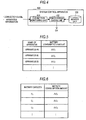
- Fig. 4 is a diagram illustrating the configuration of the system control apparatus 100 according to this embodiment.
- the system control apparatus 100 includes a connection monitoring unit 101, a power storage control unit 102, and a memory unit 103.
- connection monitoring unit 101 monitors a connection state between the connector 21 and the consumption apparatus 22.
- a connection state may be, for example, a directly connected state (e.g., a direct electrical connection is provided with a wired plug-in), a wirelessly connected state (e.g., a wireless power supply connection is provided using inductive coupling or resonant coupling), or a not connected state or separation state (e.g., no direct electrical power supply connection and no wireless power supply connection is currently available for use).
- a physical separation occurs (e.g., unplugging) or a exiting a power transfer range occurs (e.g., removing from charging station).
- the connection monitoring unit 101 inputs information (hereinafter, referred to as apparatus information) used to identify the separated consumption apparatus 22 or information (hereinafter, referred to as capacity information) regarding the battery capacity of the battery 222 mounted on the consumption apparatus 22 and information regarding the separation state into the power storage control unit 102.
- apparatus information information used to identify the separated consumption apparatus 22
- capacity information information regarding the battery capacity of the battery 222 mounted on the consumption apparatus 22
- the power storage control unit 102 determines the amount (hereinafter, a battery consumption amount) of power to be estimated by the separated consumption apparatus 22.
- the power storage control unit 102 reads consumption amount information (see Fig. 5 ), in which the names of apparatuses correspond to battery consumption amounts, from the memory unit 103 and determines the battery consumption amount corresponding to the separated consumption apparatus 22 based on the read consumption amount information.
- the power storage control unit 102 reads consumption amount information (see Fig. 6 ), in which battery capacities correspond to battery consumption amounts, from the memory unit 103 and determines the battery consumption amount corresponding to the separated consumption apparatus 22 based on the read consumption amount information.
- the power storage control unit 102 determining the battery consumption amount performs power storage control such that the extra amount of power excluding the determined battery consumption amount is stored in the power storage apparatus 14.
- the battery consumption amount may be determined by a value obtained by applying the battery capacity by a predetermined ratio.
- FIGS. 7 to 9 are diagrams illustrating the process of the system control apparatus 100 according to this embodiment.
- the system control apparatus 100 determines whether the separation of the consumption apparatus 22 is detected (S101). When the separation of the consumption apparatus 22 is detected, the system control apparatus 100 allows the process to proceed to step S102. On the other hand, when the separation of the consumption apparatus 22 is not detected, the system control apparatus 100 allows the process to proceed to step S104. When the process proceeds to step S102, the system control apparatus 100 performs a process of the separation time described below (S102). Subsequently, the system control apparatus 100 determines whether the connection of the separated consumption apparatus 22 is detected (S103).
- step S101 When the connection of the separated consumption apparatus 22 is detected, the system control apparatus 100 allows the process to proceed to step S101. On the other hand, when the connection of the separated consumption apparatus 22 is not detected, the system control apparatus 100 allows the process to proceed to step S105.
- step S101 proceeds to step S104, the system control apparatus 100 performs a process of the normal time described below (S104) and allows the process to proceed to step S105.
- step S105 the system control apparatus 100 determines whether a series of processes regarding the power storage control ends (S105). When the series of processes does not end, the system control apparatus 100 allows the process to proceed to step S101.
- the system control apparatus 100 starting the process of the separation time determines a battery consumption amount ⁇ C based on the apparatus information or the capacity information with reference to the consumption amount information (S111). Subsequently, the system control apparatus 100 changes a charging target value C based on Equation (1) below (S112).
- C 0 is a predetermined reference value. This reference value is, for example, a value that is determined in advance based on the amount of power normally consumed by the household consumption apparatus 20 usually connected to the power system.
- the charging target value C refers to a target value of the amount of power stored in the power storage apparatus 14.
- the system control apparatus 100 changing the charging target value C performs charging control based on the changed charging target value C (S113), and then ends the process of the separation time.
- C C 0 + ⁇ C
- the system control apparatus 100 starting the process of the normal time resets the charging target value C to the predetermined reference value C 0 (step S121). Subsequently, the system control apparatus 100 performs charging control based on the reset charging target value C (S122), and then the process of the normal time ends.
- the power storage control method according to the first embodiment of the present technology is applied, as described above, the power storage control is performed in consideration of the amount of power consumed by the separated consumption apparatus 22 even when the consumption apparatus 22 is separated. Accordingly, the efficient use of natural energy can be realized.
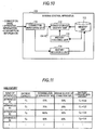
- Fig. 10 is a diagram illustrating the configuration of the system control apparatus 100 according to this embodiment.
- the system control apparatus 100 includes a connection monitoring unit 111, a power storage control unit 112, a memory unit 113, a history recording unit 114, and a history analyzing unit 115.
- the connection monitoring unit 111 monitors the connection state between the connector 21 and the consumption apparatus 22. For example, when the consumption apparatus 22 is separated from the connector 21, the connection monitoring unit 111 inputs the apparatus information used to identify the separated consumption apparatus 22, the capacity information regarding the battery capacity of the battery 222 mounted on the consumption apparatus 22, and information indicating the separation state into the power storage control unit 112. When the information indicating the separation state is input into the power storage control unit 112, the power storage control unit 112 acquires information (battery consumption amount) regarding the amount of power assumed to be consumed by the separated consumption apparatus 22 from the history analyzing unit 115. The power storage control unit 112 performs power storage control such that the extra amount of power excluding the acquired battery consumption amount is stored in the power storage apparatus 14.
- the history analyzing unit 115 determines the amount (battery consumption amount) of power assumed to be consumed by the separated consumption apparatus 22 based on the use history shown in Fig. 11 .
- the use history is acquired from the consumption apparatus 22 by the history recording unit 114 and is stored in the memory unit 113.
- the history analyzing unit 115 reads the use history shown in Fig. 11 from the memory unit 113 and extracts information corresponding to the separated consumption apparatus 22 or the battery capacity of the battery mounted on the consumption apparatus 22 from the read use history.
- the history analyzing unit 115 extracts the amounts (C 1 ⁇ 0.6 and C 1 ⁇ 0.5) of power consumed by apparatus #1 when apparatus #1 is separated once previously. In this case, the history analyzing unit 115 calculates the average C 1 ⁇ 0.55 of the extracted battery consumption amounts and determines the calculated value as a battery consumption amount ⁇ C assumed to be consumed by separated apparatus #1 when the apparatus #1 is separated.
- the case in which the average is used has been exemplified. However, another statistical value such as a median value or a weighted average may be used.
- the determined battery consumption amount ⁇ C is used by the power storage control unit 112, as described above.
- Fig. 12 is a diagram illustrating the process of the system control apparatus 100 according to this embodiment.
- the system control apparatus 100 estimates the battery consumption amount based on the use history (S131). Subsequently, the system control apparatus 100 determines whether the separation of the consumption apparatus 22 is detected (S132). When the separation of the consumption apparatus 22 is detected, the system control apparatus 100 allows the process to proceed to step S133. On the other hand, when the separation of the consumption apparatus 22 is not detected, the system control apparatus 100 allows the process to proceed to step S135. When the process proceeds to step S133, the system control apparatus 100 performs the process of the separation time (see Fig. 8 ) (S133). Subsequently, the system control apparatus 100 determines whether the connection of the separated consumption apparatus 22 is detected (S134).
- step S132 When the connection of the separated consumption apparatus 22 is detected, the system control apparatus 100 allows the process to proceed to step S132. On the other hand, when the connection of the separated consumption apparatus 22 is not detected, the system control apparatus 100 allows the process to proceed to step S136.
- step S135 the system control apparatus 100 performs the process of the normal time (see Fig. 9 ) (S135) and allows the process to proceed to step S136.
- step S136 the system control apparatus 100 determines whether a series of processes regarding the power storage control ends (S136). When the series of processes does not end, the system control apparatus 100 allows the process to proceed to step S132.
- the method of determining the battery consumption amount ⁇ C based on the use history of the consumption apparatus 22 or the battery capacity of the battery mounted on the consumption apparatus 22 has been introduced.
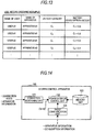
- a method of using the use history accumulated for each user when the battery consumption amount ⁇ C is determined will be introduced.
- a method of using the consumption apparatus 22 is different for each user.
- the consumption apparatus 22 is an electric vehicle
- the large amount of power consumed in the one-time use is expected to be consumed for a user who has a tendency to repeat sudden starting or sudden stopping or a user who drives a car only along a mountain road. Therefore, to realize suitable power storage control, a method of determining the battery consumption amount ⁇ C for each user is preferably used.
- a method of determining the battery consumption amount ⁇ C based on a use history shown in Fig. 13 is considered.
- the battery consumption amount ⁇ C is equal to "C 1 ⁇ 0.55" in a scenario in which user #1 uses the apparatus and the battery consumption amount ⁇ C is equal to "C 1 ⁇ 0.5" in a scenario in which user #2 uses the apparatus, when the use history exemplified in Fig. 13 is used.
- the power storage control method according to the second embodiment of the present technology when the power storage control method according to the second embodiment of the present technology is applied, the power storage control is performed in consideration of the amount of power consumed by the separated consumption apparatus 22 even when the consumption apparatus 22 is separated. Therefore, the efficient use of natural energy can be realized.
- Fig. 14 is a diagram illustrating the configuration of the system control apparatus 100 according to this embodiment.
- the system control apparatus 100 includes a connection monitoring unit 121, a power storage control unit 122, a memory unit 123, and a radio communication unit 124.
- the connection monitoring unit 121 monitors the connection state between the connector 21 and the consumption apparatus 22. For example, when the consumption apparatus 22 is separated from the connector 21, the connection monitoring unit 121 inputs information (apparatus information) used to identify the separated consumption apparatus 22, information (capacity information) regarding the battery capacity of the battery 222 mounted on the consumption apparatus 22, and information indicating the separation state into the power storage control unit 122.
- information apparatus information
- capacity information regarding the battery capacity of the battery 222 mounted on the consumption apparatus 22
- information indicating the separation state into the power storage control unit 122.
- the radio communication unit 124 receives the apparatus information or the capacity information transmitted from the consumption apparatus 22. Further, the radio communication unit 124 receives information (hereinafter, referred to as consumption information) regarding the remaining level of the battery or the battery consumption amount transmitted periodically from the separated consumption apparatus 22.
- the apparatus information, the capacity information, or the consumption information received by the radio communication unit 124 is input into the power storage control unit 122.
- the power storage control unit 122 into which such information is input determines the amount of power (battery consumption amount) assumed to be consumed by the separated consumption apparatus 22 based on the consumption information. For example, the power storage control unit 122 determines the battery consumption amount by subtracting the remaining level of the battery at the current time from the remaining level of the battery at the separation time.
- the power storage control unit 102 determining the battery consumption amount performs power storage control such that the extra amount of power excluding the determined battery consumption amount is stored in the power storage apparatus 14.
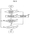
- FIGS. 15 and 16 are diagrams illustrating the process of the system control apparatus 100 according to this embodiment.
- the system control apparatus 100 determines whether the separation of the consumption apparatus 22 is detected (S141). When the separation of the consumption apparatus 22 is detected, the system control apparatus 100 allows the process to proceed to step S142. On the other hand, when the separation of the consumption apparatus 22 is not detected, the system control apparatus 100 allows the process to proceed to step S144. When the process proceeds to step S142, the system control apparatus 100 performs a process of the separation time described below (S142). Subsequently, the system control apparatus 100 determines whether the connection of the separated consumption apparatus 22 is detected (S143).
- step S141 When the connection of the separated consumption apparatus 22 is detected, the system control apparatus 100 allows the process to proceed to step S141. On the other hand, when the connection of the separated consumption apparatus 22 is not detected, the system control apparatus 100 allows the process to proceed to step S145.
- step S141 proceeds to step S144, the system control apparatus 100 performs the process (see Fig. 9 ) of the normal time (S144) and allows the process to proceed to step S145.
- step S145 the system control apparatus 100 determines whether a series of processes regarding the power storage control ends (S145). When the series of processes does not end, the system control apparatus 100 allows the process to proceed to step S141.
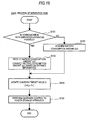
- the system control apparatus 100 starting the process of the separation time determines whether to communicate with the separated consumption apparatus 22 (step S151). When the communication is possible, the system control apparatus 100 allows the process to proceed to step S152. On the other hand, when the communication may not be possible, the system control apparatus 100 allows the process to proceed to step S153.
- the system control apparatus 100 receives the battery consumption amount ⁇ C (or may receive the remaining level of the battery) from the consumption apparatus 22 through radio communication (S152). At this time, the system control apparatus 100 may acquire distance information (information regarding the distance between the location of the power system and the consumption apparatus 22) from the consumption apparatus 22 and may correct the battery consumption amount ⁇ C.
- step S154 When the system control apparatus 100 receives the battery consumption amount ⁇ C, the process proceeds to step S154. Further, when the process proceeds to step S153, the system control apparatus 100 acquires the battery consumption amount ⁇ C based on the apparatus information or the capacity information with reference to the consumption amount information (S153). When the process proceeds to step S154, the system control apparatus 100 changes the charging target value C based on Equation (1) above (S154). Subsequently, the system control apparatus 100 performs charging control based on the changed charging target value C (S155), and then ends the process of the separation time.
- the power storage control method according to the third embodiment of the present technology is applied, as described above, the power storage control is performed in consideration of the amount of power consumed by the separated consumption apparatus 22 when the consumption apparatus 22 is separated. Accordingly, the efficient use of natural energy can be realized.
- Fig. 17 is a diagram illustrating the configuration of the system control apparatus 100 according to this embodiment.
- the system control apparatus 100 includes a connection monitoring unit 131, a power storage control unit 132, a memory unit 133, a destination information acquiring unit 134, and a consumption amount estimating unit 135.
- the connection monitoring unit 131 monitors the connection state between the connector 21 and the consumption apparatus 22. For example, when the consumption apparatus 22 is separated from the connector 21, the connection monitoring unit 131 inputs the apparatus information used to identify the separated consumption apparatus 22, the capacity information regarding the battery capacity of the battery 222 mounted on the consumption apparatus 22, and information indicating the separation state into the power storage control unit 112. When the information indicating the separation state is input into the power storage control unit 132, the power storage control unit 132 acquires information (battery consumption amount) regarding the amount of power assumed to be consumed by the separated consumption apparatus 22 from the history analyzing unit 135. The power storage control unit 132 performs power storage control such that the extra amount of power excluding the acquired battery consumption amount is stored in the power storage apparatus 14.
- the consumption amount estimating unit 135 estimates the battery consumption amount based on destination information acquired from the consumption apparatus 22 by the destination information acquiring unit 134. For example, when a user operates a navigation apparatus (see Fig. 18 ) mounted on the consumption apparatus 22 to input a destination, the destination information indicating the destination is transmitted from the navigation apparatus or the consumption apparatus 22 mounting the navigation apparatus. Then, the destination information acquiring unit 134 acquires the destination information indicating the destination from the consumption apparatus 22 through radio communication or power line communication. The destination information acquired by the destination information acquiring unit 134 is input into the consumption amount estimating unit 135.
- the consumption amount estimating unit 135 calculates a distance between the current location to the destination and calculates the battery consumption amount ⁇ C of the separated consumption apparatus 22 by calculating the amount of power to be consumed by the consumption apparatus 22 in accordance with the distance.
- information regarding the amount of power to be consumed by the consumption apparatus 22 based on a unit distance is assumed to be retained by the consumption amount estimating unit 135.
- the calculated battery consumption amount ⁇ C is used by the power storage control unit 132, as described above.
- Fig. 19 is a diagram illustrating the process of the system control apparatus 100 according to this embodiment.
- the system control apparatus 100 estimates the battery consumption amount based on the destination information (S161). Subsequently, the system control apparatus 100 determines whether the separation of the consumption apparatus 22 is detected (S162). When the separation of the consumption apparatus 22 is detected, the system control apparatus 100 allows the process to proceed to step S163. On the other hand, when the separation of the consumption apparatus 22 is not detected, the system control apparatus 100 allows the process to proceed to step S165. When the process proceeds to step S163, the system control apparatus 100 performs the process of the separation time (see Fig. 8 ) (S163). Subsequently, the system control apparatus 100 determines whether the connection of the separated consumption apparatus 22 is detected (S164).
- step S162 When the connection of the separated consumption apparatus 22 is detected, the system control apparatus 100 allows the process to proceed to step S162. On the other hand, when the connection of the separated consumption apparatus 22 is not detected, the system control apparatus 100 allows the process to proceed to step S166.
- step S165 the system control apparatus 100 performs the process of the normal time (see Fig. 9 ) (S165) and allows the process to proceed to step S166.
- step S166 the system control apparatus 100 determines whether a series of processes regarding the power storage control ends (S166). When the series of processes does not end, the system control apparatus 100 allows the process to proceed to step S162.
- the power storage control method according to the fourth embodiment of the present technology when the power storage control method according to the fourth embodiment of the present technology is applied, the power storage control is performed in consideration of the amount of power consumed by the separated consumption apparatus 22 even when the consumption apparatus 22 is separated. Therefore, the efficient use of natural energy can be realized.
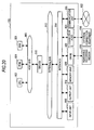
- the functions of the constituent elements of the above-described system control apparatus 100 can be realized by, for example, a hardware configuration shown in Fig. 20 . That is, the functions of the units are realized by controlling the hardware shown in Fig. 20 by a computer program. Further, the hardware has any form and examples of the hardware include a personal computer, a cellular phone, a PHS, a portable information terminal such as a PDA, a game console, and various information home appliances. PHS is an abbreviation for personal handy-phone system. PDA is an abbreviation for personal digital assistant.
- the hardware includes a CPU 902, a ROM 904, a RAM 906, a host bus 908, and a bridge 910.
- the hardware further includes an external bus 912, an interface 914, an input unit 916, an output unit 918, a memory unit 920, a drive 922, a connection port 924, and a communication unit 926.
- CPU is an abbreviation for central processing unit.
- ROM is an abbreviation for read-only memory.
- RAM is an abbreviation for random access memory.
- the CPU 902 functions as an arithmetic processing device or a control device.
- the CPU 902 controls all or some of the processes of the constituent units based on various programs recorded in the ROM 904, the RAM 906, the memory unit 920, or a removable recording medium 928.
- the ROM 904 is a unit that stores data or the like used for a program read by the CPU 902 or calculation.
- the RAM 906 temporarily or permanently stores the program read by the CPU 902 or various parameters appropriately changed when the program is executed.
- the constituent units are connected to each other via the host bus 908 capable of transmitting data at high speed.
- the host bus 908 is connected to the external bus 912, which transmits data at relatively low speed, via the bridge 910.
- a mouse, a keyboard, a touch panel, a button, a switch, or a lever is used as the input unit 916.
- a remote controller capable of transmitting a control signal through an infrared ray or other radio waves may be used as the input unit 916 in some cases.
- a display apparatus such as a CRT, an LCD, a PDP, or an ELD
- an audio output apparatus such as a speaker or a headphone, a printer, a cellular phone, or facsimile, which can notify a user of acquired information in a visual or auditory manner
- CRT is an abbreviation for cathode ray tube
- LCD is an abbreviation for liquid crystal display
- PDP is an abbreviation for plasma display panel.
- ELD is an abbreviation for electro-luminescence display.
- the memory unit 920 is a device that stores various kinds of data.
- a magnetic memory device such as an HDD, a semiconductor memory device, an optical memory device, or a magneto-optical memory device is used as the memory unit 920.
- HDD is an abbreviation for hard disk drive.
- the drive 922 is a device that reads information recorded in the removable recording medium 928, such as a magnetic disk, an optical disc, a magneto-optical disc, or a semiconductor memory or writes information on the removable recording medium 928.
- the removable recording medium 928 is, for example, a DVD medium, a Blu-ray medium, an HD DVD medium, or one of various semiconductor memory media.
- the removable recording medium 928 may be an IC card or an electronic apparatus mounting a non-contact type IC chip.
- IC is an abbreviation for integrated circuit.
- the connection port 924 is a port that connects external connection equipment 930 such as a USB port, an IEEE 1394 port, a SCSI, an RS-232 C port, or an optical audio terminal.
- the external connection equipment 930 is, for example, a printer, a portable music player, a digital camera, a digital video camera, or an IC recorder.
- USB is an abbreviation for universal serial bus.
- SCSI is an abbreviation for small computer system interface.
- the communication unit 926 is a communication device which is connected to a network 932 and is, for example, a wired or wireless LAN, the Bluetooth (registered trademark), a communication card for WUSB, a router for optical communication, a router for ADSL, or a modem for various kinds of communication.
- the network 932 connected to the communication unit 926 is configured by networks connected in a wired or wireless manner and is, for example, the Internet, a household LAN, infrared communication, visible light communication, broadcast, or satellite communication, or the like.
- LAN is an abbreviation for local area network.
- WUSB is an abbreviation for wireless USB.
- ADSL is an abbreviation for asymmetric digital subscriber line.
- the summarized technical character can be realized using various kinds of information processing apparatuses such as PCs, game consoles, information terminals, information home appliances, or car navigation systems.
- the above-described first to fourth embodiments of the present technology can be combined for use.
- the use history is used in a case where the use history can be used
- the battery consumption amount is acquired by radio communication in a case where radio communication can be used
- the battery consumption amount is estimated from the destination information in a case where the destination information can be acquired
- a method of using a predetermined battery consumption amount is used in a case where any method may not be used.
- methods of combining the above-described first to fourth embodiments can be determined arbitrarily.
- An apparatus (power storage control apparatus) and a method embodying the technical character according to the above-described first to fourth embodiments can be configured as follows.
- a power storage control apparatus described below in (1) can adjust the amount of power to be stored in a storage apparatus in consideration of the power consumed by a separated consumption apparatus when the consumption apparatus is separated. Therefore, the power corresponding to power used to charge a battery of the consumption apparatus can be stored in advance in the power storage apparatus.
- the power generated from natural energy can be stored in advance as the power used to charge the consumption apparatus, the efficient use of natural energy is realized.
- a power storage control apparatus comprises: a power storage control unit configured to: (a) determine a connection state of a consumption apparatus with a power supply; (b) determine an expected amount of power usage by the consumption apparatus in a connected state; and (c) adjusting a target value of power storage for a power storage apparatus based on a change in connection state and the expected amount of power usage by the consumption apparatus.
- the connection state is one of (i) a wirelessly connected state, (ii) a directly connected state, and (iii) a not connected state.
- the consumption apparatus is configured to wirelessly connect to the power supply to perform a wireless power transfer.
- a wireless power supply connection is provided using inductive coupling.
- a wireless power supply connection is provided using resonant coupling.
- the consumption apparatus is configured to plug into to the power supply to perform a wired power transfer over a direct electrical connection.
- the expected amount of power usage is determined based on stored consumption amount information.
- the target value is adjusted when the consumption apparatus is separated from the power supply.
- the target value is adjusted based on schedule information of the consumption apparatus.
- the target value of power storage is adjusted by providing a control signal to the power storage apparatus.
- the power storage control apparatus further comprises: a connection monitoring unit for monitoring a connection state of the consumption apparatus with the power supply, wherein the power storage control unit receives data, from the connection monitoring unit, including at least a connection state of the consumption apparatus.
- the power storage control apparatus further comprises: a memory unit storing consumption amount information for the consumption apparatus.
- the expected amount of power usage is determined by using a value obtained based on a battery capacity of the consumption apparatus and a predetermined ratio.
- the target value is set based on a sum of a reference value indicative of the amount of power normally consumed by at least one household consumption apparatus and expected amount of power usage by the consumption apparatus.
- the target value is reset to a reference value indicative of the amount of power normally consumed by at least one household consumption apparatus when the consumption apparatus is in a connected state.
- the connection monitoring unit includes a history recording unit and a history analyzing unit, and the expected amount of power usage is determined based on a history of use of the consumption apparatus. In an example embodiment, the expected amount of power usage is determined using at least one of an average, a median, and a weighted average. In an example embodiment, the expected amount of power usage is determined based on a history of use of a specific user.
- the connection monitoring unit provides consumption apparatus information including identification information.
- the connection monitoring unit provides consumption amount information including at least one of a battery capacity, a battery consumption amount, and a remaining level of battery power.
- the power storage control apparatus further comprises: a destination information acquiring unit; and a consumption amount estimating unit that estimates a battery consumption amount based on destination information acquired by the destination information acquiring unit.
- the destination information acquiring unit receives a transmission from a navigation apparatus mounted in the consumption apparatus.
- the destination information acquiring unit receives a transmission via at least one of a radio communication and power line communication.
- the consumption amount estimating unit calculates a distance between a location of the consumption apparatus and the power supply and calculates a battery consumption amount of the consumption apparatus by calculating the expected amount of power to be consumed by the consumption apparatus based on the distance.
- the power supply is configured to connect to a plurality of consumption apparatuses and the power storage control unit is configured to determine an expected amount of power usage for each of the plurality of consumption apparatuses.
- stored consumption amount information includes information for a working day and for a non-working day.
- the power storage apparatus is configured to receive power from power generation equipment that generates power from natural energy, the power generation equipment including at least one of a photovoltaic panel, wind power generation equipment, hydraulic power generation equipment, geothermal power generation equipment, and biomass power generation equipment.
- the power storage apparatus is configured to sell power stored in the power storage apparatus to a power company.
- the consumption apparatus includes an information supply unit configured to transmit information from the consumption apparatus to a power storage control unit when the consumption apparatus is connected to the power supply, and wherein the transmitted information includes at least one of apparatus information and capacity information.
- the capacity information includes at least one of battery capacity and a remaining level of the battery power.
- the apparatus information includes at least one of identification information specifying the battery and identification information specifying the consumption apparatus.
- the consumption apparatus includes an information supply unit configured to transmit information from the consumption apparatus to a power storage control unit when the consumption apparatus is connected to the power supply, and wherein the information supply unit calculates an amount of power consumed by the consumption apparatus prior to connecting to the power supply.
- the consumption apparatus includes an information supply unit configured to transmit information from the consumption apparatus to a power storage control unit when the consumption apparatus is connected to the power supply, and wherein the information supply unit transmits user identification information for the consumption apparatus.
- the consumption apparatus includes an information supply unit configured to transmit information from the consumption apparatus to a power storage control unit when the consumption apparatus is connected to the power supply, and wherein the information supply unit transmits the information by power line communication.
- the consumption apparatus is at least one of an electric vehicle, an electric scooter, an electric bicycle, a cellular phone, a portable information terminal, and a portable battery.
- the consumption apparatus includes a driving unit, a battery, a connection unit, and an information supply unit.
- the power storage control apparatus further comprises: a radio communication unit that receives distance information indicative of a distance between the location of the consumption apparatus and the power supply.
- the power storage control apparatus further comprises: a radio communication unit that receives distance information indicative of a distance between the current location of the consumption apparatus and a destination input into a navigation apparatus that is mounted in the consumption apparatus.
- the power storage control apparatus further comprises: a radio communication unit that receives distance information indicative of an estimated distance based on a destination input into a navigation apparatus that is mounted in the consumption apparatus.
- a navigation apparatus is mounted in the consumption apparatus and provides destination information for transmission to the power storage control unit.
- a power storage control method comprises: determining a connection state of a consumption apparatus with a power supply; determining an expected amount of power usage by the consumption apparatus in a connected state; and adjusting a target value of power storage for a power storage apparatus based on a change in connection state and the expected amount of power usage by the consumption apparatus.
- the connection state is one of (i) a wirelessly connected state, (ii) a directly connected state, and (iii) a not connected state.
- the consumption apparatus is configured to wirelessly connect to the power supply to perform a wireless power transfer.
- a wireless power supply connection is provided using inductive coupling.
- a wireless power supply connection is provided using resonant coupling.
- the consumption apparatus is configured to plug into to the power supply to perform a wired power transfer over a direct electrical connection.
- the expected amount of power usage is determined based on stored consumption amount information.
- the target value is adjusted when the consumption apparatus is separated from the power supply.
- the target value is adjusted based on schedule information of the consumption apparatus.
- the target value of power storage is adjusted by providing a control signal to the power storage apparatus.
- the power storage control method further comprises: monitoring a connection state of the consumption apparatus with the power supply, and receiving data including at least a connection state of the consumption apparatus.
- the power storage control method further comprises: storing consumption amount information for the consumption apparatus.
- the expected amount of power usage is determined by using a value obtained based on a battery capacity of the consumption apparatus and a predetermined ratio.
- the target value is set based on a sum of a reference value indicative of the amount of power normally consumed by at least one household consumption apparatus and expected amount of power usage by the consumption apparatus.
- the target value is reset to a reference value indicative of the amount of power normally consumed by at least one household consumption apparatus when the consumption apparatus is in a connected state.
- the connection monitoring unit includes a history recording unit and a history analyzing unit, and the expected amount of power usage is determined based on a history of use of the consumption apparatus. In an example embodiment, the expected amount of power usage is determined using at least one of an average, a median, and a weighted average. In an example embodiment, the expected amount of power usage is determined based on a history of use of a specific user. In an example embodiment, the connection monitoring unit provides consumption apparatus information including identification information. In an example embodiment, the connection monitoring unit provides consumption amount information including at least one of a battery capacity, a battery consumption amount, and a remaining level of battery power.
- the power storage control method further comprises: acquiring destination information; and estimating a battery consumption amount based on the destination information.
- the destination information acquiring unit receives a transmission from a navigation apparatus mounted in the consumption apparatus.
- the destination information acquiring unit receives a transmission via at least one of a radio communication and power line communication.
- a distance between a location of the consumption apparatus and the power supply is calculated and a battery consumption amount of the consumption apparatus is calculated by calculating the expected amount of power to be consumed by the consumption apparatus based on the distance.
- the power supply is configured to connect to a plurality of consumption apparatuses and an expected amount of power usage for each of the plurality of consumption apparatuses is determined.
- stored consumption amount information includes information for a working day and for a non-working day.
- the power storage apparatus is configured to receive power from power generation equipment that generates power from natural energy, the power generation equipment including at least one of a photovoltaic panel, wind power generation equipment, hydraulic power generation equipment, geothermal power generation equipment, and biomass power generation equipment.
- the power storage apparatus is configured to sell power stored in the power storage apparatus to a power company.
- the consumption apparatus includes an information supply unit configured to transmit information from the consumption apparatus to a power storage control unit when the consumption apparatus is connected to the power supply, and wherein the transmitted information includes at least one of apparatus information and capacity information.
- the capacity information includes at least one of battery capacity and a remaining level of the battery power.
- the apparatus information includes at least one of identification information specifying the battery and identification information specifying the consumption apparatus.
- the consumption apparatus includes an information supply unit configured to transmit information from the consumption apparatus to a power storage control unit when the consumption apparatus is connected to the power supply, and wherein the information supply unit calculates an amount of power consumed by the consumption apparatus prior to connecting to the power supply.
- the consumption apparatus includes an information supply unit configured to transmit information from the consumption apparatus to a power storage control unit when the consumption apparatus is connected to the power supply, and wherein the information supply unit transmits user identification information for the consumption apparatus.
- the consumption apparatus includes an information supply unit configured to transmit information from the consumption apparatus to a power storage control unit when the consumption apparatus is connected to the power supply, and wherein the information supply unit transmits the information by power line communication.
- the consumption apparatus is at least one of an electric vehicle, an electric scooter, an electric bicycle, a cellular phone, a portable information terminal, and a portable battery.
- the consumption apparatus includes a driving unit, a battery, a connection unit, and an information supply unit.
- the power storage control method further comprises: receiving distance information indicative of a distance between the location of the consumption apparatus and the power supply.
- the power storage control method further comprises: receiving distance information indicative of a distance between the current location of the consumption apparatus and a destination input into a navigation apparatus that is mounted in the consumption apparatus. In an example embodiment, the power storage control method further comprises: receiving distance information indicative of an estimated distance based on a destination input into a navigation apparatus that is mounted in the consumption apparatus. In an example embodiment, a navigation apparatus is mounted in the consumption apparatus and provides destination information for transmission to the power storage control unit.
- a consumption apparatus comprises: a connection unit configured to connect to a power supply; and an information supply unit configured to transmit information from the consumption apparatus to a power storage control unit when the consumption apparatus is connected to the power supply, wherein the transmitted information is configured to allow the power storage control unit to: (a) determine an expected amount of power usage by the consumption apparatus, and (b) adjust a target value of power storage for a power storage apparatus based on the expected amount of power usage by the consumption apparatus.
- a connection state of the connection unit with a power supply is one of (i) a wirelessly connected state, (ii) a directly connected state, and (iii) a not connected state.
- connection unit is configured to wirelessly connect to the power supply to perform a wireless power transfer.
- a wireless power supply connection is provided using inductive coupling.
- a wireless power supply connection is provided using resonant coupling.
- the connection unit is configured to plug into to the power supply to perform a wired power transfer over a direct electrical connection.
- the expected amount of power usage is determined based on stored consumption amount information.
- the target value is adjusted when the consumption apparatus is separated from the power supply.
- the target value is adjusted based on schedule information of the consumption apparatus.
- the target value of power storage is adjusted by providing a control signal to the power storage apparatus.
- a connection state of the connection unit with the power supply is monitored by a connection monitoring unit, wherein the power storage control unit receives data, from the connection monitoring unit, including at least a connection state of the connection unit.
- a memory unit stores consumption amount information for the consumption apparatus.
- the expected amount of power usage is determined by using a value obtained based on a battery capacity of the consumption apparatus and a predetermined ratio.
- the target value is set based on a sum of a reference value indicative of the amount of power normally consumed by at least one household consumption apparatus and expected amount of power usage by the consumption apparatus.
- a connection monitoring unit includes a history recording unit and a history analyzing unit, and the expected amount of power usage is determined based on a history of use of the consumption apparatus. In an example embodiment, the expected amount of power usage is determined using at least one of an average, a median, and a weighted average. In an example embodiment, the expected amount of power usage is determined based on a history of use of a specific user. In an example embodiment, a connection monitoring unit provides consumption apparatus information including identification information.
- a connection monitoring unit provides consumption amount information including at least one of a battery capacity, a battery consumption amount, and a remaining level of battery power.
- the information supply unit provides destination information to a destination information acquiring unit, and a consumption amount estimating unit estimates a battery consumption amount based on destination information acquired by the destination information acquiring unit.
- the destination information acquiring unit receives a transmission from a navigation apparatus mounted in the consumption apparatus.
- the destination information acquiring unit receives a transmission via at least one of a radio communication and power line communication.
- the consumption amount estimating unit calculates a distance between a location of the consumption apparatus and the power supply and calculates a battery consumption amount of the consumption apparatus by calculating the expected amount of power to be consumed by the consumption apparatus based on the distance.
- the power supply is configured to connect to a plurality of consumption apparatuses and the power storage control unit is configured to determine an expected amount of power usage for each of the plurality of consumption apparatuses.
- stored consumption amount information includes information for a working day and for a non-working day.
- the power storage apparatus is configured to receive power from power generation equipment that generates power from natural energy, the power generation equipment including at least one of a photovoltaic panel, wind power generation equipment, hydraulic power generation equipment, geothermal power generation equipment, and biomass power generation equipment.
- the power storage apparatus is configured to sell power stored in the power storage apparatus to a power company.
- the transmitted information includes at least one of apparatus information and capacity information.
- the capacity information includes at least one of battery capacity and a remaining level of the battery power.
- the apparatus information includes at least one of identification information specifying the battery and identification information specifying the consumption apparatus.
- the information supply unit calculates an amount of power consumed by the consumption apparatus prior to connecting to the power supply.
- the information supply unit transmits user identification information for the consumption apparatus. In an example embodiment, the information supply unit transmits the information by power line communication. In an example embodiment, the consumption apparatus is at least one of an electric vehicle, an electric scooter, an electric bicycle, a cellular phone, a portable information terminal, and a portable battery. In an example embodiment, the consumption apparatus includes a driving unit, a battery, a connection unit, and an information supply unit. In an example embodiment, the consumption apparatus further comprises: a radio communication unit that transmits distance information indicative of a distance between the location of the consumption apparatus and the power supply.
- the consumption apparatus further comprises: a radio communication unit that transmits distance information indicative of a distance between the current location of the consumption apparatus and a destination input into a navigation apparatus that is mounted in the consumption apparatus.
- the consumption apparatus further comprises: a radio communication unit that transmits distance information indicative of an estimated distance based on a destination input into a navigation apparatus that is mounted in the consumption apparatus.
- a navigation apparatus is mounted in the consumption apparatus and provides destination information for transmission to the power storage control unit.
- a power storage control method comprises: connecting a consumption apparatus to a power supply; and transmitting information from the consumption apparatus to a power storage control unit when the consumption apparatus is connected to the power supply, wherein the transmitted information is configured to allow the power storage control unit to: (a) determine an expected amount of power usage by the consumption apparatus, and (b) adjust a target value of power storage for a power storage apparatus based on the expected amount of power usage by the consumption apparatus.
- a connection state of the consumption apparatus with the power supply is one of (i) a wirelessly connected state, (ii) a directly connected state, and (iii) a not connected state.
- the consumption apparatus is configured to wirelessly connect to the power supply to perform a wireless power transfer.
- a wireless power supply connection is provided using inductive coupling. In an example embodiment, a wireless power supply connection is provided using resonant coupling. In an example embodiment, the consumption apparatus is configured to plug into to the power supply to perform a wired power transfer over a direct electrical connection. In an example embodiment, the expected amount of power usage is determined based on stored consumption amount information. In an example embodiment, the target value is adjusted when the consumption apparatus is separated from the power supply. In an example embodiment, the target value is adjusted based on schedule information of the consumption apparatus. In an example embodiment, the target value of power storage is adjusted by providing a control signal to the power storage apparatus.
- a connection state of the consumption apparatus with the power supply is monitored by a connection monitoring unit, wherein the power storage control unit receives data, from the connection monitoring unit, including at least a connection state of the consumption apparatus.
- a memory unit stores consumption amount information for the consumption apparatus.
- the expected amount of power usage is determined by using a value obtained based on a battery capacity of the consumption apparatus and a predetermined ratio.
- the target value is set based on a sum of a reference value indicative of the amount of power normally consumed by at least one household consumption apparatus and expected amount of power usage by the consumption apparatus.
- a connection monitoring unit includes a history recording unit and a history analyzing unit, and the expected amount of power usage is determined based on a history of use of the consumption apparatus. In an example embodiment, the expected amount of power usage is determined using at least one of an average, a median, and a weighted average. In an example embodiment, the expected amount of power usage is determined based on a history of use of a specific user. In an example embodiment, a connection monitoring unit provides consumption apparatus information including identification information.
- a connection monitoring unit provides consumption amount information including at least one of a battery capacity, a battery consumption amount, and a remaining level of battery power.
- the power storage control method further comprises: providing destination information to a destination information acquiring unit, wherein a consumption amount estimating unit estimates a battery consumption amount based on destination information acquired by the destination information acquiring unit.
- the destination information acquiring unit receives a transmission from a navigation apparatus mounted in the consumption apparatus.
- the destination information acquiring unit receives a transmission via at least one of a radio communication and power line communication.
- the consumption amount estimating unit calculates a distance between a location of the consumption apparatus and the power supply and calculates a battery consumption amount of the consumption apparatus by calculating the expected amount of power to be consumed by the consumption apparatus based on the distance.
- the power supply is configured to connect to a plurality of consumption apparatuses and the power storage control unit is configured to determine an expected amount of power usage for each of the plurality of consumption apparatuses.
- stored consumption amount information includes information for a working day and for a non-working day.
- the power storage apparatus is configured to receive power from power generation equipment that generates power from natural energy, the power generation equipment including at least one of a photovoltaic panel, wind power generation equipment, hydraulic power generation equipment, geothermal power generation equipment, and biomass power generation equipment.
- the power storage apparatus is configured to sell power stored in the power storage apparatus to a power company.
- the transmitted information includes at least one of apparatus information and capacity information.
- the capacity information includes at least one of battery capacity and a remaining level of the battery power.
- the apparatus information includes at least one of identification information specifying the battery and identification information specifying the consumption apparatus.
- the power storage control method further comprises: calculating an amount of power consumed by the consumption apparatus prior to connecting to the power supply.
- the transmitted information includes user identification information for the consumption apparatus.
- the information is transmitted by power line communication.
- the consumption apparatus is at least one of an electric vehicle, an electric scooter, an electric bicycle, a cellular phone, a portable information terminal, and a portable battery.
- the consumption apparatus includes a driving unit, a battery, a connection unit, and an information supply unit.
- the transmitted information is transmitted by a radio communication unit that transmits distance information indicative of a distance between the location of the consumption apparatus and the power supply.
- the transmitted information is transmitted by a radio communication unit that transmits distance information indicative of a distance between the current location of the consumption apparatus and a destination input into a navigation apparatus that is mounted in the consumption apparatus.
- the transmitted information is transmitted by a radio communication unit that transmits distance information indicative of an estimated distance based on a destination input into a navigation apparatus that is mounted in the consumption apparatus.
- a navigation apparatus is mounted in the consumption apparatus and provides destination information for transmission to the power storage control unit.
- a power storage control apparatus comprises: a radio communication unit configured to receive radio communications from a consumption apparatus; and a power storage control unit configured to: (a) receive a radio communication from a consumption apparatus; (b) determine an expected amount of power usage by the consumption apparatus based on the received communication; and (c) adjust a target value of power storage for the power storage apparatus based on a the received communication and the expected amount of power usage by the consumption apparatus.
- a connection state of the consumption apparatus with a power supply is one of (i) a wirelessly connected state, (ii) a directly connected state, and (iii) a not connected state.
- the consumption apparatus is configured to wirelessly connect to a power supply to perform a wireless power transfer.
- a wireless power supply connection is provided using inductive coupling. In an example embodiment, a wireless power supply connection is provided using resonant coupling. In an example embodiment, the consumption apparatus is configured to plug into to a power supply to perform a wired power transfer over a direct electrical connection. In an example embodiment, the expected amount of power usage is determined based on stored consumption amount information. In an example embodiment, the target value is adjusted when the consumption apparatus is separated from a power supply. In an example embodiment, the target value is adjusted based on schedule information of the consumption apparatus. In an example embodiment, the target value of power storage is adjusted by providing a control signal to the power storage apparatus.
- the power storage control apparatus further comprises: a connection monitoring unit for monitoring a connection state of the consumption apparatus with a power supply, wherein the power storage control unit receives data, from the connection monitoring unit, including at least a connection state of the consumption apparatus.
- the power storage control apparatus further comprises: a memory unit storing consumption amount information for the consumption apparatus.
- the expected amount of power usage is determined by using a value obtained based on a battery capacity of the consumption apparatus and a predetermined ratio.
- the target value is set based on a sum of a reference value indicative of the amount of power normally consumed by at least one household consumption apparatus and expected amount of power usage by the consumption apparatus.
- a connection monitoring unit includes a history recording unit and a history analyzing unit, and the expected amount of power usage is determined based on a history of use of the consumption apparatus. In an example embodiment, the expected amount of power usage is determined using at least one of an average, a median, and a weighted average. In an example embodiment, the expected amount of power usage is determined based on a history of use of a specific user. In an example embodiment, a connection monitoring unit provides consumption apparatus information including identification information.
- a connection monitoring unit provides consumption amount information including at least one of a battery capacity, a battery consumption amount, and a remaining level of battery power.
- the power storage control apparatus further comprises: a destination information acquiring unit; and a consumption amount estimating unit that estimates a battery consumption amount based on destination information acquired by the destination information acquiring unit.
- the destination information acquiring unit receives a transmission from a navigation apparatus mounted in the consumption apparatus.
- the destination information acquiring unit receives a transmission via at least one of a radio communication and power line communication.
- the consumption amount estimating unit calculates a distance between a location of the consumption apparatus and the power supply and calculates a battery consumption amount of the consumption apparatus by calculating the expected amount of power to be consumed by the consumption apparatus based on the distance.
- a power supply is configured to connect to a plurality of consumption apparatuses and the power storage control unit is configured to determine an expected amount of power usage for each of the plurality of consumption apparatuses.
- stored consumption amount information includes information for a working day and for a non-working day.
- the power storage apparatus is configured to receive power from power generation equipment that generates power from natural energy, the power generation equipment including at least one of a photovoltaic panel, wind power generation equipment, hydraulic power generation equipment, geothermal power generation equipment, and biomass power generation equipment.
- the power storage apparatus is configured to sell power stored in the power storage apparatus to a power company.
- the consumption apparatus includes an information supply unit configured to transmit information from the consumption apparatus to a power storage control unit, and wherein the transmitted information includes at least one of apparatus information and capacity information.
- the capacity information includes at least one of battery capacity and a remaining level of the battery power.
- the apparatus information includes at least one of identification information specifying the battery and identification information specifying the consumption apparatus.
- the consumption apparatus includes an information supply unit configured to transmit information from the consumption apparatus to a power storage control unit, and wherein the information supply unit calculates an amount of power consumed by the consumption apparatus prior to transmitting information to the power storage control unit.
- the consumption apparatus includes an information supply unit configured to transmit information from the consumption apparatus to a power storage control unit, and wherein the information supply unit transmits user identification information for the consumption apparatus.
- the consumption apparatus is at least one of an electric vehicle, an electric scooter, an electric bicycle, a cellular phone, a portable information terminal, and a portable battery.
- the consumption apparatus includes a driving unit, a battery, a connection unit, and an information supply unit.
- the radio communication unit receives distance information indicative of a distance between the location of the consumption apparatus and a power supply. In an example embodiment, the radio communication unit receives distance information indicative of a distance between the current location of the consumption apparatus and a destination input into a navigation apparatus that is mounted in the consumption apparatus. In an example embodiment, the radio communication unit receives distance information indicative of an estimated distance based on a destination input into a navigation apparatus that is mounted in the consumption apparatus. In an example embodiment, a navigation apparatus is mounted in the consumption apparatus and provides destination information for transmission to the power storage control unit.
- a power storage control method comprises: receiving a radio communication from a consumption apparatus; determining an expected amount of power usage by the consumption apparatus based on the received communication; and adjusting a target value of power storage for the power storage apparatus based on a the received communication and the expected amount of power usage by the consumption apparatus.
- a connection state of the consumption apparatus with a power supply is one of (i) a wirelessly connected state, (ii) a directly connected state, and (iii) a not connected state.
- the consumption apparatus is configured to wirelessly connect to a power supply to perform a wireless power transfer.
- a wireless power supply connection is provided using inductive coupling.
- a wireless power supply connection is provided using resonant coupling.
- the consumption apparatus is configured to plug into to a power supply to perform a wired power transfer over a direct electrical connection.
- the expected amount of power usage is determined based on stored consumption amount information.
- the target value is adjusted when the consumption apparatus is separated from a power supply.
- the target value is adjusted based on schedule information of the consumption apparatus.
- the target value of power storage is adjusted by providing a control signal to the power storage apparatus.
- the power storage control method further comprises: monitoring a connection state of the consumption apparatus with a power supply, and receiving data including at least a connection state of the consumption apparatus: In an example embodiment, the power storage control method further comprises: storing consumption amount information for the consumption apparatus. In an example embodiment, the expected amount of power usage is determined by using a value obtained based on a battery capacity of the consumption apparatus and a predetermined ratio. In an example embodiment, the target value is set based on a sum of a reference value indicative of the amount of power normally consumed by at least one household consumption apparatus and expected amount of power usage by the consumption apparatus. In an example embodiment, the target value is reset to a reference value indicative of the amount of power normally consumed by at least one household consumption apparatus when the consumption apparatus is in a connected state.
- a connection monitoring unit includes a history recording unit and a history analyzing unit, and the expected amount of power usage is determined based on a history of use of the consumption apparatus. In an example embodiment, the expected amount of power usage is determined using at least one of an average, a median, and a weighted average. In an example embodiment, the expected amount of power usage is determined based on a history of use of a specific user. In an example embodiment, a connection monitoring unit provides consumption apparatus information including identification information. In an example embodiment, a connection monitoring unit provides consumption amount information including at least one of a battery capacity, a battery consumption amount, and a remaining level of battery power.
- the power storage control method further comprises: acquiring destination information; and estimating a battery consumption amount based on the destination information.
- the destination information acquiring unit receives a transmission from a navigation apparatus mounted in the consumption apparatus.
- the destination information acquiring unit receives a transmission via at least one of a radio communication and power line communication.
- a distance between a location of the consumption apparatus and a power supply is calculated and a battery consumption amount of the consumption apparatus is calculated by calculating the expected amount of power to be consumed by the consumption apparatus based on the distance.
- a power supply is configured to connect to a plurality of consumption apparatuses and an expected amount of power usage for each of the plurality of consumption apparatuses is determined.
- stored consumption amount information includes information for a working day and for a non-working day.
- the power storage apparatus is configured to receive power from power generation equipment that generates power from natural energy, the power generation equipment including at least one of a photovoltaic panel, wind power generation equipment, hydraulic power generation equipment, geothermal power generation equipment, and biomass power generation equipment.
- the power storage apparatus is configured to sell power stored in the power storage apparatus to a power company.
- the consumption apparatus includes an information supply unit configured to transmit information from the consumption apparatus to a power storage control unit, and wherein the transmitted information includes at least one of apparatus information and capacity information.
- the capacity information includes at least one of battery capacity and a remaining level of the battery power.
- the apparatus information includes at least one of identification information specifying the battery and identification information specifying the consumption apparatus.
- the consumption apparatus includes an information supply unit configured to transmit information from the consumption apparatus to a power storage control unit, and wherein the information supply unit calculates an amount of power consumed by the consumption apparatus prior to transmitting information to the power storage control unit.
- the consumption apparatus includes an information supply unit configured to transmit information from the consumption apparatus to a power storage control unit, and wherein the information supply unit transmits user identification information for the consumption apparatus.
- the consumption apparatus is at least one of an electric vehicle, an electric scooter, an electric bicycle, a cellular phone, a portable information terminal, and a portable battery.
- the consumption apparatus includes a driving unit, a battery, a connection unit, and an information supply unit.
- the received communication includes distance information indicative of a distance between the location of the consumption apparatus and a power supply.
- the received communication includes distance information indicative of a distance between the current location of the consumption apparatus and a destination input into a navigation apparatus that is mounted in the consumption apparatus.
- the received communication includes distance information indicative of an estimated distance based on a destination input into a navigation apparatus that is mounted in the consumption apparatus.
- a navigation apparatus is mounted in the consumption apparatus and provides destination information for transmission to the power storage control unit.
- a consumption apparatus comprises: an information supply unit for determining consumption amount information; and a radio communication unit configured to transmit consumption amount information from the consumption apparatus via radio communication to a power storage control unit, wherein the transmitted consumption amount information is configured to allow the power storage control unit to: (a) determine an expected amount of power usage by the consumption apparatus, and (b) adjust a target value of power storage for a power storage apparatus based on the expected amount of power usage by the consumption apparatus.
- a connection state of the consumption apparatus with a power supply is one of (i) a wirelessly connected state, (ii) a directly connected state, and (iii) a not connected state.
- the consumption apparatus is configured to wirelessly connect to a power supply to perform a wireless power transfer.
- a wireless power supply connection is provided using inductive coupling.
- a wireless power supply connection is provided using resonant coupling.
- the consumption apparatus is configured to plug into to a power supply to perform a wired power transfer over a direct electrical connection.
- the expected amount of power usage is determined based on stored consumption amount information.
- the target value is adjusted when the consumption apparatus is separated from a power supply.
- the target value is adjusted based on schedule information of the consumption apparatus.
- the target value of power storage is adjusted by providing a control signal to the power storage apparatus.
- a connection state of the consumption apparatus with a power supply is monitored by a connection monitoring unit, wherein the power storage control unit receives data, from the connection monitoring unit, including at least a connection state of the consumption apparatus.
- a memory unit stores consumption amount information for the consumption apparatus.
- the expected amount of power usage is determined by using a value obtained based on a battery capacity of the consumption apparatus and a predetermined ratio.
- the target value is set based on a sum of a reference value indicative of the amount of power normally consumed by at least one household consumption apparatus and expected amount of power usage by the consumption apparatus.
- a connection monitoring unit includes a history recording unit and a history analyzing unit, and the expected amount of power usage is determined based on a history of use of the consumption apparatus. In an example embodiment, the expected amount of power usage is determined using at least one of an average, a median, and a weighted average. In an example embodiment, the expected amount of power usage is determined based on a history of use of a specific user. In an example embodiment, a connection monitoring unit provides consumption apparatus information including identification information.
- a connection monitoring unit provides consumption amount information including at least one of a battery capacity, a battery consumption amount, and a remaining level of battery power.
- the information supply unit provides destination information to a destination information acquiring unit, and a consumption amount estimating unit estimates a battery consumption amount based on destination information acquired by the destination information acquiring unit.
- the destination information acquiring unit receives a transmission from a navigation apparatus mounted in the consumption apparatus.
- the destination information acquiring unit receives a transmission via at least one of a radio communication and power line communication.
- the consumption amount estimating unit calculates a distance between a location of the consumption apparatus and a power supply and calculates a battery consumption amount of the consumption apparatus by calculating the expected amount of power to be consumed by the consumption apparatus based on the distance.
- a power supply is configured to connect to a plurality of consumption apparatuses and the power storage control unit is configured to determine an expected amount of power usage for each of the plurality of consumption apparatuses.
- stored consumption amount information includes information for a working day and for a non-working day.
- the power storage apparatus is configured to receive power from power generation equipment that generates power from natural energy, the power generation equipment including at least one of a photovoltaic panel, wind power generation equipment, hydraulic power generation equipment, geothermal power generation equipment, and biomass power generation equipment.
- the power storage apparatus is configured to sell power stored in the power storage apparatus to a power company.
- the transmitted consumption amount information includes at least one of apparatus information and capacity information.
- the capacity information includes at least one of battery capacity and a remaining level of the battery power.
- the apparatus information includes at least one of identification information specifying the battery and identification information specifying the consumption apparatus.
- the information supply unit calculates an amount of power consumed by the consumption apparatus prior to the radio communication unit transmitting the consumption amount information to the power supply.
- the information supply unit provides user identification information for the consumption apparatus.
- the consumption apparatus is at least one of an electric vehicle, an electric scooter, an electric bicycle, a cellular phone, a portable information terminal, and a portable battery.
- the consumption apparatus includes a driving unit, a battery, a connection unit, and an information supply unit.
- the radio communication unit transmits distance information indicative of a distance between the location of the consumption apparatus and a power supply.
- the radio communication unit transmits distance information indicative of a distance between the current location of the consumption apparatus and a destination input into a navigation apparatus that is mounted in the consumption apparatus. In an example embodiment, the radio communication unit transmits distance information indicative of an estimated distance based on a destination input into a navigation apparatus that is mounted in the consumption apparatus. In an example embodiment, a navigation apparatus is mounted in the consumption apparatus and provides destination information for transmission to the power storage control unit.
- a power storage control method comprises: determining consumption amount information; and transmitting the consumption amount information from the consumption apparatus via radio communication to a power storage control unit, wherein the transmitted consumption amount information is configured to allow the power storage control unit to: (a) determine an expected amount of power usage by the consumption apparatus, and (b) adjust a target value of power storage for a power storage apparatus based on the expected amount of power usage by the consumption apparatus.
- a connection state of the consumption apparatus with a power supply is one of (i) a wirelessly connected state, (ii) a directly connected state, and (iii) a not connected state.
- the consumption apparatus is configured to wirelessly connect to a power supply to perform a wireless power transfer.
- a wireless power supply connection is provided using inductive coupling. In an example embodiment, a wireless power supply connection is provided using resonant coupling. In an example embodiment, the consumption apparatus is configured to plug into to a power supply to perform a wired power transfer over a direct electrical connection. In an example embodiment, the expected amount of power usage is determined based on stored consumption amount information. In an example embodiment, the target value is adjusted when the consumption apparatus is separated from a power supply. In an example embodiment, the target value is adjusted based on schedule information of the consumption apparatus. In an example embodiment, the target value of power storage is adjusted by providing a control signal to the power storage apparatus.
- a connection state of the consumption apparatus with a power supply is monitored by a connection monitoring unit, wherein the power storage control unit receives data, from the connection monitoring unit, including at least a connection state of the consumption apparatus.
- a memory unit stores consumption amount information for the consumption apparatus.
- the expected amount of power usage is determined by using a value obtained based on a battery capacity of the consumption apparatus and a predetermined ratio.
- the target value is set based on a sum of a reference value indicative of the amount of power normally consumed by at least one household consumption apparatus and expected amount of power usage by the consumption apparatus.
- a connection monitoring unit includes a history recording unit and a history analyzing unit, and the expected amount of power usage is determined based on a history of use of the consumption apparatus. In an example embodiment, the expected amount of power usage is determined using at least one of an average, a median, and a weighted average. In an example embodiment, the expected amount of power usage is determined based on a history of use of a specific user. In an example embodiment, a connection monitoring unit provides consumption apparatus information including identification information.
- a connection monitoring unit provides consumption amount information including at least one of a battery capacity, a battery consumption amount, and a remaining level of battery power.
- the power storage control method further comprises: providing destination information to a destination information acquiring unit, wherein a consumption amount estimating unit estimates a battery consumption amount based on destination information acquired by the destination information acquiring unit.
- the destination information acquiring unit receives a transmission from a navigation apparatus mounted in the consumption apparatus.
- the destination information acquiring unit receives a transmission via at least one of a radio communication and power line communication.
- the consumption amount estimating unit calculates a distance between a location of the consumption apparatus and a power supply and calculates a battery consumption amount of the consumption apparatus by calculating the expected amount of power to be consumed by the consumption apparatus based on the distance.
- a power supply is configured to connect to a plurality of consumption apparatuses and the power storage control unit is configured to determine an expected amount of power usage for each of the plurality of consumption apparatuses.
- stored consumption amount information includes information for a working day and for a non-working day.
- the power storage apparatus is configured to receive power from power generation equipment that generates power from natural energy, the power generation equipment including at least one of a photovoltaic panel, wind power generation equipment, hydraulic power generation equipment, geothermal power generation equipment, and biomass power generation equipment.
- the power storage apparatus is configured to sell power stored in the power storage apparatus to a power company.
- the transmitted consumption amount information includes at least one of apparatus information and capacity information.
- the capacity information includes at least one of battery capacity and a remaining level of the battery power.
- the apparatus information includes at least one of identification information specifying the battery and identification information specifying the consumption apparatus.
- the power storage control method further comprises: calculating an amount of power consumed by the consumption apparatus prior to transmitting the consumption amount information to the power storage control unit.
- the transmitted information includes user identification information for the consumption apparatus.
- the consumption apparatus is at least one of an electric vehicle, an electric scooter, an electric bicycle, a cellular phone, a portable information terminal, and a portable battery.
- the consumption apparatus includes a driving unit, a battery, a connection unit, and an information supply unit.
- the transmitted consumption amount information is transmitted by a radio communication unit that transmits distance information indicative of a distance between the location of the consumption apparatus and the power supply.
- the transmitted consumption amount information is transmitted by a radio communication unit that transmits distance information indicative of a distance between the current location of the consumption apparatus and a destination input into a navigation apparatus that is mounted in the consumption apparatus.
- the transmitted consumption amount information is transmitted by a radio communication unit that transmits distance information indicative of an estimated distance based on a destination input into a navigation apparatus that is mounted in the consumption apparatus.
- a navigation apparatus is mounted in the consumption apparatus and provides destination information for transmission to the power storage control unit.
- the history recording unit 114 is examples of a consumption amount acquiring unit and a history retaining unit.
- the history analyzing unit 115 is an example of the consumption estimating unit.
- the radio communication unit 225 is an example of the transmission apparatus.
- the battery consumption amount when the fixed battery consumption amount set for each apparatus or each battery capacity is used, the battery consumption amount may be switched by providing the battery consumption amounts on a working day and a non-working day or any other schedule information. Accordingly, a target value of the amount of power stored in the power storage apparatus may be adjusted based on schedule information of the consumption apparatus. For example, schedule information such as a work schedule may be provided to the system by a user.
- schedule information such as a work schedule may be provided to the system by a user.
- schedule information such as a work schedule may be provided to the system by a user.
- a method of calculating a total amount of average amounts of battery consumed in a day by a plurality of frequently used consumption apparatuses and controlling the power storage based on the total amount without using the use history of each apparatus may be considered. Furthermore, a method of charging the consumption apparatus 22 preferentially with the power stored in the power storage apparatus 14 is also effective.
Landscapes
- Engineering & Computer Science (AREA)
- Power Engineering (AREA)
- Charge And Discharge Circuits For Batteries Or The Like (AREA)
- Secondary Cells (AREA)
- Electric Propulsion And Braking For Vehicles (AREA)
- Supply And Distribution Of Alternating Current (AREA)
Claims (15)
- Energiespeichersteuervorrichtung (100), die Folgendes umfasst:eine Energiespeichersteuereinheit (102), die zu Folgendem konfiguriert ist:(a) Bestimmen eines Verbindungszustands einer Verbrauchsvorrichtung (22) mit einer Stromversorgung, wobei die Verbrauchsvorrichtung eine Batterie (222) umfasst, die verwendet wird, wenn die Verbrauchsvorrichtung von der Stromversorgung getrennt ist;(b) Bestimmen einer erwarteten Stromverbrauchsmenge durch die Verbrauchsvorrichtung in einem verbundenen Zustand und(c) Anpassen eines Sollwerts der Energiespeicherung für eine Energiespeichervorrichtung basierend auf einer Änderung in einem Verbindungszustand und der erwarteten Stromverbrauchsmenge durch die Verbrauchsvorrichtung.
- Energiespeichersteuervorrichtung nach Anspruch 1, wobei der Verbindungszustand einer der Folgenden ist: (i) ein drahtlos verbundener Zustand, (ii) ein direkt verbundener Zustand und (iii) ein nicht verbundener Zustand.
- Energiespeichersteuervorrichtung nach Anspruch 1, wobei die Verbrauchsvorrichtung dazu konfiguriert ist, sich drahtlos mit der Stromversorgung zu verbinden, um eine drahtlose Stromübertragung auszuführen.
- Energiespeichersteuervorrichtung nach Anspruch 3, wobei eine drahtlose Stromversorgungsverbindung mittels induktiver Kopplung bereitgestellt ist.
- Energiespeichersteuervorrichtung nach Anspruch 3, wobei eine drahtlose Stromversorgungsverbindung mittels resonanter Kopplung bereitgestellt ist.
- Energiespeichersteuervorrichtung nach Anspruch 1, wobei die Verbrauchsvorrichtung dazu konfiguriert ist, sich an die Stromversorgung anzuschließen, um eine drahtgebundene Stromübertragung über eine direkte elektrische Verbindung auszuführen.
- Energiespeichersteuervorrichtung nach Anspruch 1, wobei die erwartete Stromverbrauchsmenge basierend auf gespeicherten Verbrauchsmengeninformationen bestimmt wird.
- Energiespeichersteuervorrichtung nach Anspruch 1, wobei der Sollwert angepasst wird, wenn die Verbrauchsvorrichtung von der Stromversorgung getrennt wird.
- Energiespeichersteuervorrichtung nach Anspruch 1, die ferner Folgendes umfasst:eine Verbindungsüberwachungseinheit (101) zum Überwachen eines Verbindungszustands der Verbrauchsvorrichtung mit der Stromversorgung,wobei die Energiespeichersteuereinheit Daten von der Verbindungsüberwachungseinheit empfängt, die mindestens einen Verbindungszustand der Verbrauchsvorrichtung umfassen.
- Energiespeichersteuervorrichtung nach Anspruch 1, die ferner Folgendes umfasst:eine Bestimmungsort-Informationsbeschaffungseinheit (134); undeine Verbrauchsmengenschätzeinheit (135), die eine Batterieverbrauchsmenge basierend auf den Bestimmungsort-Informationen, die durch die Bestimmungsort-Informationsbeschaffungseinheit beschafft werden, schätzt, wobei die Verbrauchsmengenschätzeinheit eine Distanz zwischen einem Ort der Verbrauchsvorrichtung und der Stromversorgung berechnet und eine Batterieverbrauchsmenge der Verbrauchsvorrichtung durch Berechnen der erwarteten Strommenge, die durch die Verbrauchsvorrichtung verbraucht werden wird, basierend auf der Distanz berechnet.
- Energiespeichersteuervorrichtung nach Anspruch 1, wobei die Stromversorgung dazu konfiguriert ist, sich mit mehreren Verbrauchsvorrichtungen zu verbinden, und die Energiespeichersteuereinheit dazu konfiguriert ist, eine erwartete Stromverbrauchsmenge für jede der mehreren Verbrauchsvorrichtungen zu bestimmen.
- Energiespeichersteuervorrichtung nach Anspruch 1, wobei die Verbrauchsvorrichtung eine Informationsversorgungseinheit (224) umfasst, die dazu konfiguriert ist, Informationen von der Verbrauchsvorrichtung an eine Energiespeichersteuereinheit zu senden, wenn die Verbrauchsvorrichtung mit der Stromversorgung verbunden ist, und
wobei die gesendeten Informationen Vorrichtungsinformationen und/oder Kapazitätsinformationen umfassen, wobei die Kapazitätsinformationen die Batteriekapazität und/oder eine verbleibende Höhe der Batterieleistung umfassen. - Energiespeichersteuervorrichtung nach Anspruch 1, wobei die Verbrauchsvorrichtung eine Informationsversorgungseinheit umfasst, die dazu konfiguriert ist, Informationen von der Verbrauchsvorrichtung an eine Energiespeichersteuereinheit zu senden, wenn die Verbrauchsvorrichtung mit der Stromversorgung verbunden ist, und
wobei die Informationsversorgungseinheit Identifikationsinformationen für die Verbrauchsvorrichtung sendet. - Energiespeichersteuervorrichtung nach Anspruch 1, wobei die Verbrauchsvorrichtung eine Informationsversorgungseinheit umfasst, die dazu konfiguriert ist, Informationen von der Verbrauchsvorrichtung an eine Energiespeichersteuereinheit zu senden, wenn die Verbrauchsvorrichtung mit der Stromversorgung verbunden ist, und
wobei die Informationsversorgungseinheit die Informationen mittels Stromleitungskommunikation sendet. - Energiespeichersteuervorrichtung nach Anspruch 1, die ferner Folgendes umfasst:eine Funkkommunikationseinheit (124), die Distanzinformationen empfängt, die bezeichnend für eine Distanz zwischen dem aktuellen Ort der Verbrauchsvorrichtung und einer Bestimmungsorteingabe in eine Navigationsvorrichtung, die in der Verbrauchsvorrichtung montiert ist, sind.
Applications Claiming Priority (1)
| Application Number | Priority Date | Filing Date | Title |
|---|---|---|---|
| JP2011208993A JP5786593B2 (ja) | 2011-09-26 | 2011-09-26 | 蓄電制御装置、及び蓄電制御方法 |
Publications (2)
| Publication Number | Publication Date |
|---|---|
| EP2575236A1 EP2575236A1 (de) | 2013-04-03 |
| EP2575236B1 true EP2575236B1 (de) | 2014-05-14 |
Family
ID=47221117
Family Applications (1)
| Application Number | Title | Priority Date | Filing Date |
|---|---|---|---|
| EP12184810.5A Not-in-force EP2575236B1 (de) | 2011-09-26 | 2012-09-18 | Stromspeicherungssteuerungsvorrichtung und Stromspeicherungssteuerungsverfahren |
Country Status (4)
| Country | Link |
|---|---|
| US (1) | US9472978B2 (de) |
| EP (1) | EP2575236B1 (de) |
| JP (1) | JP5786593B2 (de) |
| CN (1) | CN103117569B (de) |
Families Citing this family (6)
| Publication number | Priority date | Publication date | Assignee | Title |
|---|---|---|---|---|
| CN103457282A (zh) * | 2013-08-20 | 2013-12-18 | 国家电网公司 | 家用充电桩供能系统和方法 |
| CN103475012A (zh) * | 2013-08-20 | 2013-12-25 | 国家电网公司 | 分布式发电电量分配系统和方法 |
| CN103941841A (zh) * | 2014-04-21 | 2014-07-23 | 可牛网络技术(北京)有限公司 | 获取设备剩余可用时间的方法及装置 |
| US9936457B2 (en) * | 2016-03-29 | 2018-04-03 | International Business Machines Corporation | Ensuring battery reserve for mobile communication |
| JP6688726B2 (ja) * | 2016-12-26 | 2020-04-28 | 株式会社シマノ | 自転車用制御装置および自転車用制御システム |
| US20250083551A1 (en) * | 2021-05-28 | 2025-03-13 | Nippon Telegraph And Telephone Corporation | Charge and discharge management apparatus, charge and discharge management method and program |
Family Cites Families (17)
| Publication number | Priority date | Publication date | Assignee | Title |
|---|---|---|---|---|
| US5963457A (en) * | 1994-03-18 | 1999-10-05 | Hitachi, Ltd. | Electrical power distribution monitoring system and method |
| US20080106146A1 (en) * | 2004-11-02 | 2008-05-08 | Lg Electronics Inc. | Management System for In-House Power Quantity Consumed |
| US8890505B2 (en) * | 2007-08-28 | 2014-11-18 | Causam Energy, Inc. | System and method for estimating and providing dispatchable operating reserve energy capacity through use of active load management |
| JP5240762B2 (ja) * | 2008-05-14 | 2013-07-17 | トヨタ自動車株式会社 | 建物の電源システム |
| JP2010213507A (ja) | 2009-03-11 | 2010-09-24 | Chugoku Electric Power Co Inc:The | 自然エネルギー併用型蓄電システム、および自然エネルギー併用型蓄電方法 |
| JP2010252587A (ja) * | 2009-04-20 | 2010-11-04 | San'eisha Mfg Co Ltd | 充電スタンド |
| JP5391886B2 (ja) * | 2009-07-10 | 2014-01-15 | パナソニック株式会社 | 充電手段付き電気機器、充電手段付き電気機器の制御方法、およびそのプログラム |
| JP5563574B2 (ja) * | 2009-07-15 | 2014-07-30 | パナソニック株式会社 | 電力制御システム、電力制御方法、電力制御装置及び電力制御プログラム |
| JP2011125122A (ja) * | 2009-12-09 | 2011-06-23 | Sony Corp | バッテリ制御システム、バッテリ制御装置、バッテリ制御方法およびプログラム |
| JP5645244B2 (ja) * | 2010-02-05 | 2014-12-24 | パナソニックIpマネジメント株式会社 | エネルギー需給制御システム |
| DE102011003993A1 (de) * | 2010-02-15 | 2011-08-18 | DENSO CORPORATION, Aichi-pref. | Laderegler und Navigationsvorrichtung für ein Plug-In-Fahrzeug |
| JP5471940B2 (ja) * | 2010-02-15 | 2014-04-16 | 株式会社デンソー | プラグイン車両の充電制御装置及び車両用ナビゲーション装置 |
| WO2011162405A1 (ja) * | 2010-06-25 | 2011-12-29 | シャープ株式会社 | 複数の電気機器を効率的に動作させる電気管理システム、及びそのための電気機器、中央管理装置、コンピュータプログラムとその記憶媒体、並びに中央管理装置における電気機器の管理方法 |
| US20120053742A1 (en) * | 2010-08-30 | 2012-03-01 | Sony Corporation | Information processing apparatus, information processing method, information processing system, and transportation means |
| MX2013007333A (es) * | 2010-12-21 | 2014-01-23 | Nissan Motor | Sistema de carga rapida, aparato de control, metodo para controlar la cantidad de energia almacenada, y programada. |
| US9651927B2 (en) * | 2011-11-24 | 2017-05-16 | Kyocera Corporation | Power supply control system and power supply control method |
| JP5694393B2 (ja) * | 2013-01-17 | 2015-04-01 | シャープ株式会社 | サーバ装置、電子機器、通信システム、情報処理方法、およびプログラム |
-
2011
- 2011-09-26 JP JP2011208993A patent/JP5786593B2/ja not_active Expired - Fee Related
-
2012
- 2012-09-14 US US13/617,974 patent/US9472978B2/en not_active Expired - Fee Related
- 2012-09-18 EP EP12184810.5A patent/EP2575236B1/de not_active Not-in-force
- 2012-09-19 CN CN201210350513.6A patent/CN103117569B/zh not_active Expired - Fee Related
Also Published As
| Publication number | Publication date |
|---|---|
| CN103117569B (zh) | 2020-01-17 |
| JP5786593B2 (ja) | 2015-09-30 |
| US20130079944A1 (en) | 2013-03-28 |
| US9472978B2 (en) | 2016-10-18 |
| JP2013070575A (ja) | 2013-04-18 |
| EP2575236A1 (de) | 2013-04-03 |
| CN103117569A (zh) | 2013-05-22 |
Similar Documents
| Publication | Publication Date | Title |
|---|---|---|
| US11710979B2 (en) | Method and apparatus for charging a battery with AC power based on state of battery related information | |
| EP2736755B1 (de) | System zur überwachung einer batterieladevorrichtung | |
| EP2575236B1 (de) | Stromspeicherungssteuerungsvorrichtung und Stromspeicherungssteuerungsverfahren | |
| US9124099B2 (en) | Storage battery system | |
| CN104396115B (zh) | 控制二次电池单元的充电容量平衡操作的设备和方法 | |
| CN112440830B (zh) | 电动车辆 | |
| US9721447B2 (en) | Display of rechargeable battery charge notification | |
| US10164298B2 (en) | Power storage device, control method, control device, power storage system, maintenance system, electric vehicle, and electronic equipment | |
| EP2903216B1 (de) | Verwaltungssystem, verwaltungsverfahren und vorrichtung | |
| US8816644B2 (en) | Interrupting the charging status of a rechargeable battery | |
| CN110879361A (zh) | 一种电池的剩余电量的估计方法、装置和电子设备 | |
| EP2903215B1 (de) | Verwaltungsverfahren, steuerungsvorrichtung und kommunikationsverarbeitungsvorrichtung | |
| CN105340150A (zh) | 充电状态管理方法、充电状态管理设备以及程序 | |
| CN103986211A (zh) | 一种智能充电控制方法 | |
| CN103677199A (zh) | 信息处理的方法以及电子设备 | |
| US20140028265A1 (en) | Battery control unit, charge-discharge unit, electric power control unit, battery unit, electric vehicle | |
| KR102382196B1 (ko) | 육상전력공급장치(amp)로부터 전력을 공급받아 에너지를 이용하는 중소형 선박용 에너지관리시스템 | |
| CN105809933A (zh) | 一种单通道光伏电池板电力线载波智能通信模块 | |
| CN110601383B (zh) | 激光充电方法及相关设备 | |
| CN223413440U (zh) | 一种储能电池soc外置安全检测装置 | |
| CN119297450A (zh) | 智能换电柜的低温控制系统、方法、换电柜和存储介质 | |
| CN103887854A (zh) | 一种移动终端及其充电控制方法 | |
| CN116365660A (zh) | 一种大功率充电器充电控制方法、装置及存储介质 | |
| WO2016017016A1 (ja) | データ処理装置、エネルギー管理システム、データ処理方法及びプログラム |
Legal Events
| Date | Code | Title | Description |
|---|---|---|---|
| PUAI | Public reference made under article 153(3) epc to a published international application that has entered the european phase |
Free format text: ORIGINAL CODE: 0009012 |
|
| 17P | Request for examination filed |
Effective date: 20121008 |
|
| AK | Designated contracting states |
Kind code of ref document: A1 Designated state(s): AL AT BE BG CH CY CZ DE DK EE ES FI FR GB GR HR HU IE IS IT LI LT LU LV MC MK MT NL NO PL PT RO RS SE SI SK SM TR |
|
| AX | Request for extension of the european patent |
Extension state: BA ME |
|
| RIC1 | Information provided on ipc code assigned before grant |
Ipc: H02J 7/35 20060101ALI20131108BHEP Ipc: H02J 7/34 20060101AFI20131108BHEP |
|
| GRAP | Despatch of communication of intention to grant a patent |
Free format text: ORIGINAL CODE: EPIDOSNIGR1 |
|
| INTG | Intention to grant announced |
Effective date: 20140121 |
|
| GRAS | Grant fee paid |
Free format text: ORIGINAL CODE: EPIDOSNIGR3 |
|
| GRAA | (expected) grant |
Free format text: ORIGINAL CODE: 0009210 |
|
| AK | Designated contracting states |
Kind code of ref document: B1 Designated state(s): AL AT BE BG CH CY CZ DE DK EE ES FI FR GB GR HR HU IE IS IT LI LT LU LV MC MK MT NL NO PL PT RO RS SE SI SK SM TR |
|
| REG | Reference to a national code |
Ref country code: GB Ref legal event code: FG4D |
|
| REG | Reference to a national code |
Ref country code: AT Ref legal event code: REF Ref document number: 668926 Country of ref document: AT Kind code of ref document: T Effective date: 20140615 |
|
| REG | Reference to a national code |
Ref country code: IE Ref legal event code: FG4D |
|
| REG | Reference to a national code |
Ref country code: DE Ref legal event code: R096 Ref document number: 602012001751 Country of ref document: DE Effective date: 20140626 |
|
| REG | Reference to a national code |
Ref country code: NL Ref legal event code: VDEP Effective date: 20140514 Ref country code: AT Ref legal event code: MK05 Ref document number: 668926 Country of ref document: AT Kind code of ref document: T Effective date: 20140514 |
|
| REG | Reference to a national code |
Ref country code: LT Ref legal event code: MG4D |
|
| PG25 | Lapsed in a contracting state [announced via postgrant information from national office to epo] |
Ref country code: NO Free format text: LAPSE BECAUSE OF FAILURE TO SUBMIT A TRANSLATION OF THE DESCRIPTION OR TO PAY THE FEE WITHIN THE PRESCRIBED TIME-LIMIT Effective date: 20140814 Ref country code: CY Free format text: LAPSE BECAUSE OF FAILURE TO SUBMIT A TRANSLATION OF THE DESCRIPTION OR TO PAY THE FEE WITHIN THE PRESCRIBED TIME-LIMIT Effective date: 20140514 Ref country code: GR Free format text: LAPSE BECAUSE OF FAILURE TO SUBMIT A TRANSLATION OF THE DESCRIPTION OR TO PAY THE FEE WITHIN THE PRESCRIBED TIME-LIMIT Effective date: 20140815 Ref country code: LT Free format text: LAPSE BECAUSE OF FAILURE TO SUBMIT A TRANSLATION OF THE DESCRIPTION OR TO PAY THE FEE WITHIN THE PRESCRIBED TIME-LIMIT Effective date: 20140514 Ref country code: IS Free format text: LAPSE BECAUSE OF FAILURE TO SUBMIT A TRANSLATION OF THE DESCRIPTION OR TO PAY THE FEE WITHIN THE PRESCRIBED TIME-LIMIT Effective date: 20140914 Ref country code: FI Free format text: LAPSE BECAUSE OF FAILURE TO SUBMIT A TRANSLATION OF THE DESCRIPTION OR TO PAY THE FEE WITHIN THE PRESCRIBED TIME-LIMIT Effective date: 20140514 |
|
| PG25 | Lapsed in a contracting state [announced via postgrant information from national office to epo] |
Ref country code: ES Free format text: LAPSE BECAUSE OF FAILURE TO SUBMIT A TRANSLATION OF THE DESCRIPTION OR TO PAY THE FEE WITHIN THE PRESCRIBED TIME-LIMIT Effective date: 20140514 Ref country code: RS Free format text: LAPSE BECAUSE OF FAILURE TO SUBMIT A TRANSLATION OF THE DESCRIPTION OR TO PAY THE FEE WITHIN THE PRESCRIBED TIME-LIMIT Effective date: 20140514 Ref country code: SE Free format text: LAPSE BECAUSE OF FAILURE TO SUBMIT A TRANSLATION OF THE DESCRIPTION OR TO PAY THE FEE WITHIN THE PRESCRIBED TIME-LIMIT Effective date: 20140514 Ref country code: LV Free format text: LAPSE BECAUSE OF FAILURE TO SUBMIT A TRANSLATION OF THE DESCRIPTION OR TO PAY THE FEE WITHIN THE PRESCRIBED TIME-LIMIT Effective date: 20140514 Ref country code: HR Free format text: LAPSE BECAUSE OF FAILURE TO SUBMIT A TRANSLATION OF THE DESCRIPTION OR TO PAY THE FEE WITHIN THE PRESCRIBED TIME-LIMIT Effective date: 20140514 Ref country code: AT Free format text: LAPSE BECAUSE OF FAILURE TO SUBMIT A TRANSLATION OF THE DESCRIPTION OR TO PAY THE FEE WITHIN THE PRESCRIBED TIME-LIMIT Effective date: 20140514 Ref country code: PL Free format text: LAPSE BECAUSE OF FAILURE TO SUBMIT A TRANSLATION OF THE DESCRIPTION OR TO PAY THE FEE WITHIN THE PRESCRIBED TIME-LIMIT Effective date: 20140514 |
|
| PG25 | Lapsed in a contracting state [announced via postgrant information from national office to epo] |
Ref country code: PT Free format text: LAPSE BECAUSE OF FAILURE TO SUBMIT A TRANSLATION OF THE DESCRIPTION OR TO PAY THE FEE WITHIN THE PRESCRIBED TIME-LIMIT Effective date: 20140915 |
|
| PG25 | Lapsed in a contracting state [announced via postgrant information from national office to epo] |
Ref country code: RO Free format text: LAPSE BECAUSE OF FAILURE TO SUBMIT A TRANSLATION OF THE DESCRIPTION OR TO PAY THE FEE WITHIN THE PRESCRIBED TIME-LIMIT Effective date: 20140514 Ref country code: CZ Free format text: LAPSE BECAUSE OF FAILURE TO SUBMIT A TRANSLATION OF THE DESCRIPTION OR TO PAY THE FEE WITHIN THE PRESCRIBED TIME-LIMIT Effective date: 20140514 Ref country code: DK Free format text: LAPSE BECAUSE OF FAILURE TO SUBMIT A TRANSLATION OF THE DESCRIPTION OR TO PAY THE FEE WITHIN THE PRESCRIBED TIME-LIMIT Effective date: 20140514 Ref country code: BE Free format text: LAPSE BECAUSE OF FAILURE TO SUBMIT A TRANSLATION OF THE DESCRIPTION OR TO PAY THE FEE WITHIN THE PRESCRIBED TIME-LIMIT Effective date: 20140514 Ref country code: SK Free format text: LAPSE BECAUSE OF FAILURE TO SUBMIT A TRANSLATION OF THE DESCRIPTION OR TO PAY THE FEE WITHIN THE PRESCRIBED TIME-LIMIT Effective date: 20140514 Ref country code: EE Free format text: LAPSE BECAUSE OF FAILURE TO SUBMIT A TRANSLATION OF THE DESCRIPTION OR TO PAY THE FEE WITHIN THE PRESCRIBED TIME-LIMIT Effective date: 20140514 |
|
| REG | Reference to a national code |
Ref country code: DE Ref legal event code: R097 Ref document number: 602012001751 Country of ref document: DE |
|
| PG25 | Lapsed in a contracting state [announced via postgrant information from national office to epo] |
Ref country code: NL Free format text: LAPSE BECAUSE OF FAILURE TO SUBMIT A TRANSLATION OF THE DESCRIPTION OR TO PAY THE FEE WITHIN THE PRESCRIBED TIME-LIMIT Effective date: 20140514 |
|
| PLBE | No opposition filed within time limit |
Free format text: ORIGINAL CODE: 0009261 |
|
| STAA | Information on the status of an ep patent application or granted ep patent |
Free format text: STATUS: NO OPPOSITION FILED WITHIN TIME LIMIT |
|
| REG | Reference to a national code |
Ref country code: DE Ref legal event code: R084 Ref document number: 602012001751 Country of ref document: DE |
|
| 26N | No opposition filed |
Effective date: 20150217 |
|
| PG25 | Lapsed in a contracting state [announced via postgrant information from national office to epo] |
Ref country code: LU Free format text: LAPSE BECAUSE OF FAILURE TO SUBMIT A TRANSLATION OF THE DESCRIPTION OR TO PAY THE FEE WITHIN THE PRESCRIBED TIME-LIMIT Effective date: 20140918 Ref country code: IT Free format text: LAPSE BECAUSE OF FAILURE TO SUBMIT A TRANSLATION OF THE DESCRIPTION OR TO PAY THE FEE WITHIN THE PRESCRIBED TIME-LIMIT Effective date: 20140514 Ref country code: MC Free format text: LAPSE BECAUSE OF FAILURE TO SUBMIT A TRANSLATION OF THE DESCRIPTION OR TO PAY THE FEE WITHIN THE PRESCRIBED TIME-LIMIT Effective date: 20140514 |
|
| REG | Reference to a national code |
Ref country code: GB Ref legal event code: 746 Effective date: 20150420 |
|
| REG | Reference to a national code |
Ref country code: DE Ref legal event code: R097 Ref document number: 602012001751 Country of ref document: DE Effective date: 20150217 Ref country code: DE Ref legal event code: R084 Ref document number: 602012001751 Country of ref document: DE Effective date: 20150410 |
|
| REG | Reference to a national code |
Ref country code: IE Ref legal event code: MM4A |
|
| PG25 | Lapsed in a contracting state [announced via postgrant information from national office to epo] |
Ref country code: SI Free format text: LAPSE BECAUSE OF FAILURE TO SUBMIT A TRANSLATION OF THE DESCRIPTION OR TO PAY THE FEE WITHIN THE PRESCRIBED TIME-LIMIT Effective date: 20140514 |
|
| PG25 | Lapsed in a contracting state [announced via postgrant information from national office to epo] |
Ref country code: IE Free format text: LAPSE BECAUSE OF NON-PAYMENT OF DUE FEES Effective date: 20140918 |
|
| REG | Reference to a national code |
Ref country code: FR Ref legal event code: PLFP Year of fee payment: 4 |
|
| REG | Reference to a national code |
Ref country code: CH Ref legal event code: PL |
|
| PG25 | Lapsed in a contracting state [announced via postgrant information from national office to epo] |
Ref country code: SM Free format text: LAPSE BECAUSE OF FAILURE TO SUBMIT A TRANSLATION OF THE DESCRIPTION OR TO PAY THE FEE WITHIN THE PRESCRIBED TIME-LIMIT Effective date: 20140514 |
|
| PG25 | Lapsed in a contracting state [announced via postgrant information from national office to epo] |
Ref country code: MT Free format text: LAPSE BECAUSE OF FAILURE TO SUBMIT A TRANSLATION OF THE DESCRIPTION OR TO PAY THE FEE WITHIN THE PRESCRIBED TIME-LIMIT Effective date: 20140514 Ref country code: BG Free format text: LAPSE BECAUSE OF FAILURE TO SUBMIT A TRANSLATION OF THE DESCRIPTION OR TO PAY THE FEE WITHIN THE PRESCRIBED TIME-LIMIT Effective date: 20140514 |
|
| PG25 | Lapsed in a contracting state [announced via postgrant information from national office to epo] |
Ref country code: HU Free format text: LAPSE BECAUSE OF FAILURE TO SUBMIT A TRANSLATION OF THE DESCRIPTION OR TO PAY THE FEE WITHIN THE PRESCRIBED TIME-LIMIT; INVALID AB INITIO Effective date: 20120918 Ref country code: CH Free format text: LAPSE BECAUSE OF NON-PAYMENT OF DUE FEES Effective date: 20150930 Ref country code: LI Free format text: LAPSE BECAUSE OF NON-PAYMENT OF DUE FEES Effective date: 20150930 Ref country code: TR Free format text: LAPSE BECAUSE OF FAILURE TO SUBMIT A TRANSLATION OF THE DESCRIPTION OR TO PAY THE FEE WITHIN THE PRESCRIBED TIME-LIMIT Effective date: 20140514 |
|
| REG | Reference to a national code |
Ref country code: FR Ref legal event code: PLFP Year of fee payment: 5 |
|
| REG | Reference to a national code |
Ref country code: FR Ref legal event code: PLFP Year of fee payment: 6 |
|
| PG25 | Lapsed in a contracting state [announced via postgrant information from national office to epo] |
Ref country code: MK Free format text: LAPSE BECAUSE OF FAILURE TO SUBMIT A TRANSLATION OF THE DESCRIPTION OR TO PAY THE FEE WITHIN THE PRESCRIBED TIME-LIMIT Effective date: 20140514 |
|
| REG | Reference to a national code |
Ref country code: FR Ref legal event code: PLFP Year of fee payment: 7 |
|
| PG25 | Lapsed in a contracting state [announced via postgrant information from national office to epo] |
Ref country code: AL Free format text: LAPSE BECAUSE OF FAILURE TO SUBMIT A TRANSLATION OF THE DESCRIPTION OR TO PAY THE FEE WITHIN THE PRESCRIBED TIME-LIMIT Effective date: 20140514 |
|
| PGFP | Annual fee paid to national office [announced via postgrant information from national office to epo] |
Ref country code: GB Payment date: 20200921 Year of fee payment: 9 Ref country code: FR Payment date: 20200914 Year of fee payment: 9 Ref country code: DE Payment date: 20200925 Year of fee payment: 9 |
|
| REG | Reference to a national code |
Ref country code: DE Ref legal event code: R119 Ref document number: 602012001751 Country of ref document: DE |
|
| GBPC | Gb: european patent ceased through non-payment of renewal fee |
Effective date: 20210918 |
|
| PG25 | Lapsed in a contracting state [announced via postgrant information from national office to epo] |
Ref country code: GB Free format text: LAPSE BECAUSE OF NON-PAYMENT OF DUE FEES Effective date: 20210918 Ref country code: FR Free format text: LAPSE BECAUSE OF NON-PAYMENT OF DUE FEES Effective date: 20210930 Ref country code: DE Free format text: LAPSE BECAUSE OF NON-PAYMENT OF DUE FEES Effective date: 20220401 |