EP2574689A1 - Furnace for directional solidification of crystals - Google Patents
Furnace for directional solidification of crystals Download PDFInfo
- Publication number
- EP2574689A1 EP2574689A1 EP12185910A EP12185910A EP2574689A1 EP 2574689 A1 EP2574689 A1 EP 2574689A1 EP 12185910 A EP12185910 A EP 12185910A EP 12185910 A EP12185910 A EP 12185910A EP 2574689 A1 EP2574689 A1 EP 2574689A1
- Authority
- EP
- European Patent Office
- Prior art keywords
- shutters
- axis
- symmetry
- flaps
- flap
- Prior art date
- Legal status (The legal status is an assumption and is not a legal conclusion. Google has not performed a legal analysis and makes no representation as to the accuracy of the status listed.)
- Granted
Links
- 239000013078 crystal Substances 0.000 title claims abstract description 16
- 238000007711 solidification Methods 0.000 title claims description 19
- 230000008023 solidification Effects 0.000 title claims description 19
- 238000010438 heat treatment Methods 0.000 claims abstract description 32
- 125000006850 spacer group Chemical group 0.000 claims abstract description 13
- 238000004519 manufacturing process Methods 0.000 claims abstract description 6
- 239000002178 crystalline material Substances 0.000 claims abstract description 3
- 238000000034 method Methods 0.000 claims abstract 2
- 238000002844 melting Methods 0.000 claims description 12
- 230000008018 melting Effects 0.000 claims description 12
- 239000000463 material Substances 0.000 claims description 11
- 239000012768 molten material Substances 0.000 claims description 5
- 238000001816 cooling Methods 0.000 claims description 3
- XUIMIQQOPSSXEZ-UHFFFAOYSA-N Silicon Chemical compound [Si] XUIMIQQOPSSXEZ-UHFFFAOYSA-N 0.000 description 29
- 229910052710 silicon Inorganic materials 0.000 description 28
- 239000010703 silicon Substances 0.000 description 28
- 238000002425 crystallisation Methods 0.000 description 17
- 230000008025 crystallization Effects 0.000 description 17
- OKTJSMMVPCPJKN-UHFFFAOYSA-N Carbon Chemical compound [C] OKTJSMMVPCPJKN-UHFFFAOYSA-N 0.000 description 4
- VYPSYNLAJGMNEJ-UHFFFAOYSA-N Silicium dioxide Chemical compound O=[Si]=O VYPSYNLAJGMNEJ-UHFFFAOYSA-N 0.000 description 4
- 238000006073 displacement reaction Methods 0.000 description 4
- 229910002804 graphite Inorganic materials 0.000 description 4
- 239000010439 graphite Substances 0.000 description 4
- 239000012530 fluid Substances 0.000 description 3
- XKRFYHLGVUSROY-UHFFFAOYSA-N Argon Chemical compound [Ar] XKRFYHLGVUSROY-UHFFFAOYSA-N 0.000 description 2
- 239000004020 conductor Substances 0.000 description 2
- 238000005520 cutting process Methods 0.000 description 2
- 238000009413 insulation Methods 0.000 description 2
- 239000000377 silicon dioxide Substances 0.000 description 2
- 229910052786 argon Inorganic materials 0.000 description 1
- 239000011449 brick Substances 0.000 description 1
- 238000005265 energy consumption Methods 0.000 description 1
- 230000006698 induction Effects 0.000 description 1
- 239000011261 inert gas Substances 0.000 description 1
- 239000011810 insulating material Substances 0.000 description 1
- 238000012986 modification Methods 0.000 description 1
- 230000004048 modification Effects 0.000 description 1
- 229910021421 monocrystalline silicon Inorganic materials 0.000 description 1
- 229910021420 polycrystalline silicon Inorganic materials 0.000 description 1
- 230000007704 transition Effects 0.000 description 1
Images


Classifications
-
- C—CHEMISTRY; METALLURGY
- C30—CRYSTAL GROWTH
- C30B—SINGLE-CRYSTAL GROWTH; UNIDIRECTIONAL SOLIDIFICATION OF EUTECTIC MATERIAL OR UNIDIRECTIONAL DEMIXING OF EUTECTOID MATERIAL; REFINING BY ZONE-MELTING OF MATERIAL; PRODUCTION OF A HOMOGENEOUS POLYCRYSTALLINE MATERIAL WITH DEFINED STRUCTURE; SINGLE CRYSTALS OR HOMOGENEOUS POLYCRYSTALLINE MATERIAL WITH DEFINED STRUCTURE; AFTER-TREATMENT OF SINGLE CRYSTALS OR A HOMOGENEOUS POLYCRYSTALLINE MATERIAL WITH DEFINED STRUCTURE; APPARATUS THEREFOR
- C30B11/00—Single-crystal growth by normal freezing or freezing under temperature gradient, e.g. Bridgman-Stockbarger method
- C30B11/003—Heating or cooling of the melt or the crystallised material
-
- C—CHEMISTRY; METALLURGY
- C30—CRYSTAL GROWTH
- C30B—SINGLE-CRYSTAL GROWTH; UNIDIRECTIONAL SOLIDIFICATION OF EUTECTIC MATERIAL OR UNIDIRECTIONAL DEMIXING OF EUTECTOID MATERIAL; REFINING BY ZONE-MELTING OF MATERIAL; PRODUCTION OF A HOMOGENEOUS POLYCRYSTALLINE MATERIAL WITH DEFINED STRUCTURE; SINGLE CRYSTALS OR HOMOGENEOUS POLYCRYSTALLINE MATERIAL WITH DEFINED STRUCTURE; AFTER-TREATMENT OF SINGLE CRYSTALS OR A HOMOGENEOUS POLYCRYSTALLINE MATERIAL WITH DEFINED STRUCTURE; APPARATUS THEREFOR
- C30B11/00—Single-crystal growth by normal freezing or freezing under temperature gradient, e.g. Bridgman-Stockbarger method
- C30B11/006—Controlling or regulating
-
- C—CHEMISTRY; METALLURGY
- C30—CRYSTAL GROWTH
- C30B—SINGLE-CRYSTAL GROWTH; UNIDIRECTIONAL SOLIDIFICATION OF EUTECTIC MATERIAL OR UNIDIRECTIONAL DEMIXING OF EUTECTOID MATERIAL; REFINING BY ZONE-MELTING OF MATERIAL; PRODUCTION OF A HOMOGENEOUS POLYCRYSTALLINE MATERIAL WITH DEFINED STRUCTURE; SINGLE CRYSTALS OR HOMOGENEOUS POLYCRYSTALLINE MATERIAL WITH DEFINED STRUCTURE; AFTER-TREATMENT OF SINGLE CRYSTALS OR A HOMOGENEOUS POLYCRYSTALLINE MATERIAL WITH DEFINED STRUCTURE; APPARATUS THEREFOR
- C30B28/00—Production of homogeneous polycrystalline material with defined structure
- C30B28/04—Production of homogeneous polycrystalline material with defined structure from liquids
- C30B28/06—Production of homogeneous polycrystalline material with defined structure from liquids by normal freezing or freezing under temperature gradient
-
- C—CHEMISTRY; METALLURGY
- C30—CRYSTAL GROWTH
- C30B—SINGLE-CRYSTAL GROWTH; UNIDIRECTIONAL SOLIDIFICATION OF EUTECTIC MATERIAL OR UNIDIRECTIONAL DEMIXING OF EUTECTOID MATERIAL; REFINING BY ZONE-MELTING OF MATERIAL; PRODUCTION OF A HOMOGENEOUS POLYCRYSTALLINE MATERIAL WITH DEFINED STRUCTURE; SINGLE CRYSTALS OR HOMOGENEOUS POLYCRYSTALLINE MATERIAL WITH DEFINED STRUCTURE; AFTER-TREATMENT OF SINGLE CRYSTALS OR A HOMOGENEOUS POLYCRYSTALLINE MATERIAL WITH DEFINED STRUCTURE; APPARATUS THEREFOR
- C30B29/00—Single crystals or homogeneous polycrystalline material with defined structure characterised by the material or by their shape
- C30B29/02—Elements
- C30B29/06—Silicon
-
- C—CHEMISTRY; METALLURGY
- C30—CRYSTAL GROWTH
- C30B—SINGLE-CRYSTAL GROWTH; UNIDIRECTIONAL SOLIDIFICATION OF EUTECTIC MATERIAL OR UNIDIRECTIONAL DEMIXING OF EUTECTOID MATERIAL; REFINING BY ZONE-MELTING OF MATERIAL; PRODUCTION OF A HOMOGENEOUS POLYCRYSTALLINE MATERIAL WITH DEFINED STRUCTURE; SINGLE CRYSTALS OR HOMOGENEOUS POLYCRYSTALLINE MATERIAL WITH DEFINED STRUCTURE; AFTER-TREATMENT OF SINGLE CRYSTALS OR A HOMOGENEOUS POLYCRYSTALLINE MATERIAL WITH DEFINED STRUCTURE; APPARATUS THEREFOR
- C30B35/00—Apparatus not otherwise provided for, specially adapted for the growth, production or after-treatment of single crystals or of a homogeneous polycrystalline material with defined structure
-
- F—MECHANICAL ENGINEERING; LIGHTING; HEATING; WEAPONS; BLASTING
- F27—FURNACES; KILNS; OVENS; RETORTS
- F27B—FURNACES, KILNS, OVENS, OR RETORTS IN GENERAL; OPEN SINTERING OR LIKE APPARATUS
- F27B14/00—Crucible or pot furnaces
- F27B14/06—Crucible or pot furnaces heated electrically, e.g. induction crucible furnaces with or without any other source of heat
-
- F—MECHANICAL ENGINEERING; LIGHTING; HEATING; WEAPONS; BLASTING
- F27—FURNACES; KILNS; OVENS; RETORTS
- F27B—FURNACES, KILNS, OVENS, OR RETORTS IN GENERAL; OPEN SINTERING OR LIKE APPARATUS
- F27B14/00—Crucible or pot furnaces
- F27B14/08—Details peculiar to crucible or pot furnaces
- F27B14/20—Arrangement of controlling, monitoring, alarm or like devices
Definitions
- the present invention relates to a directed solidification furnace of crystals, and more particularly to such an oven for obtaining silicon ingots for the manufacture of photovoltaic solar panels.
- the principle of operation of a directed solidification furnace of crystals is as follows. Silicon chips are introduced into a silica crucible. Heating elements arranged around the side walls of the crucible or above the crucible and / or under the bottom of the crucible, then heat the crucible to melt the silicon pieces. Once the pieces of silicon are melted, the crucible is cooled to crystallize the molten silicon. The cooling of the crucible is provided from the bottom of the crucible, for example by a heat exchanger disposed under the bottom of the crucible. The crystallization of the molten silicon then begins at the bottom of the crucible. Solidification is said to be directed.
- the heat exchanger is for example a plate disposed under the heating elements of the bottom of the crucible and cooled by circulation of a fluid.
- the crucible After melting then crystallization, a silicon ingot with a different crystalline structure from that of the pieces of silicon initially introduced into the crucible is obtained.
- the crucible has a square base of the order of 1 m side and 50 cm high, and one obtains a silicon ingot of the order of 1 m side and 30 cm high, intended to be cut into calibrated bricks.
- thermal shield An example of a thermal shield that can be used is a movable flap. During the heating and melting phases, the flap is positioned between the heating elements and the heat exchanger. To ensure good thermal insulation, the flap is large enough to extend under the entire bottom of the crucible. The flap is then removed to begin crystallization. It is then necessary to provide a complete release system of the shutter to fully discover the heat exchanger.
- a first disadvantage of an oven equipped with a heat shield such as that described above lies in its larger size compared to a furnace without thermal shielding.
- Another disadvantage is related to the fact that, during the release of the flap, the exposure of the bottom of the crucible relative to the heat exchanger starts from an edge of the bottom of the crucible. The crystallization of molten silicon then tends to begin with one of the edges of the crucible. To obtain uniform crystallization of the molten silicon, it is then necessary to release the shutter as quickly as possible. However, for certain applications, it is preferable to gradually increase the surface of the bottom of the crucible exposed to the heat exchanger. In an oven equipped with a shield thermal type of that described above, this would be to the detriment of the quality of the crystallization of molten silicon.
- an object of an embodiment of the present invention is to provide a directed solidification furnace of crystals equipped with a thermal shield having a small footprint.
- Another object of an embodiment of the present invention is to provide a crystalline directed solidification furnace equipped with a thermal shielding, during the crystallization phases, to increase the surface of the bottom of the crucible exposed to the heat exchanger from the center of the crucible.
- Another object of an embodiment of the present invention is to provide a crystalline directed solidification furnace equipped with a thermal shielding, during the crystallization phases, to gradually increase the surface of the bottom of the crucible exposed to the 'heat exchanger.
- One embodiment of the present invention provides a directed solidification furnace of crystals comprising a crucible, the crucible being intended to contain the crystals and having an axis of symmetry, the furnace successively comprising, along the axis of symmetry: the crucible; heating elements; thermal shielding; a heat exchanger; the thermal shielding successively comprising, according to the axis of symmetry, two first flaps and two second flaps, the first flaps being able to deviate and approach one another and the axis of symmetry by translational movements , and the second flaps that can move away from each other and closer to each other and the axis of symmetry by translation movements, the translation directions of the first flaps and second flaps being orthogonal.
- the thermal shielding comprises supports, each first and second flap being fixed on a support, the supports being adapted to slide on a plate disposed between the flaps and the heat exchanger.
- each second flap when the first flaps are brought closer to the maximum of each other and the second flaps are brought closer to each other, each second flap is positioned at least in part between each first component and the associated medium.
- each first and second shutter has a rectangular shape and each support comprises a pointed portion directed towards the axis of symmetry.
- the first flaps are adapted to come into contact with each other and the second flaps are adapted to come into contact with one another, and one side of the portion pointed one of the supports associated with the first flaps is adapted to come into contact with one side of the pointed portion of one of the supports associated with the second flaps.
- each first flap is spaced apart from the associated support, by a distance equal to the thickness of one of the second flaps, by spacer elements.
- the spacer elements comprise a spacer connecting the edge of the first flap furthest from the axis of symmetry and the associated support, and a rod connecting the edge of the flange.
- first flap closest to the axis of symmetry and the pointed portion of the associated support, and each second flap comprises apertures adapted to receive the rods when the flaps are brought closer to the maximum of one another.
- the thermal shielding comprises a drive system adapted to separate and bring the first and second shutters, the heat exchanger being disposed between the first and second shutters on the one hand and at least one part of the drive system on the other hand.
- the drive system comprises a drive part connected to each first and second flap via a rod articulated relative to the drive part and relative to the first one. or second associated flap, the drive system further comprising a motor adapted to drive the driving part in rotation about the axis of symmetry.
- this furnace further comprises, for each first and second flap, an elongated connecting piece fixed to the edge of the first or second associated flap farthest from the axis of symmetry, the piece of elongate connection being oriented in a direction parallel to the axis of symmetry, and the rod being articulated relative to the connecting piece and relative to the drive part and oriented in a direction orthogonal to the axis of symmetry.
- An embodiment of the present invention further provides a method of manufacturing an ingot of a crystalline material, employing the oven described above, comprising the following steps: a) introducing pieces of the material into the crucible ; b) melting the pieces of material by the heating elements, the first flaps being brought closer to each other and the second flaps being brought closer to each other; c) cooling the melted material by the heat exchanger by removing the first flaps from each other and the second flaps one from the other, to cause the molten material to solidify and form the ingot.
- step a in step a), monocrystalline seeds are introduced into the crucible in addition to pieces of the material, at least part of the monocrystalline seeds not melting in step b); and in step c), the solidification of the molten material is initiated from the monocrystalline seed portion which has not melted in step b).
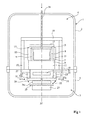
- the figure 1 is a sectional view schematically illustrating a directed solidification furnace of crystals.
- the furnace comprises an enclosure 1, for example a double-walled cylindrical enclosure of axis ⁇ 1, for example vertical.
- the adjectives "upper” and “lower” are used in relation to the axis ⁇ 1.
- the section plane corresponds to a plane of symmetry containing the axis ⁇ 1.
- the outer diameter of the chamber 1 is for example 2 meters.
- the chamber 1 is generally cooled by a system for circulating a fluid, not shown.
- the enclosure 1 comprises an upper enclosure 2 and a lower enclosure 3 respectively delimiting an upper portion 4 of the oven and a lower portion 5 of the oven.
- the upper part 4 of the furnace comprises a crucible 7, for example silica.
- the crucible is for example square base, for example 88 cm side and 42 cm high.
- Plates 9 are fixed to the side walls and to the bottom of the crucible 7.
- the plates 9 are used in particular to increase the rigidity of the crucible 7.
- the plate 9 on which the bottom of the crucible 7 rests is itself placed on a support 11.
- a Plate 13 covers the top of the crucible 7.
- the plates 9 and 13 and the support 11 are made of a thermally conductive material, for example graphite.
- Heating elements 15 are arranged around the plates 9 surrounding the side walls of the crucible 7, and a heating element 17 is disposed above the plate 13 covering the crucible 7.
- Insulating elements 19 surround the assembly constituted by the crucible 7, the plates 9 and 13, the heating elements 15 and 17, and the support 11.
- Heating elements 21 are arranged under the support 11, in the lower part 5 of the oven.
- the heating elements 15, 17 and 21 consist for example of electrical resistors comprising for example several heating bars.
- Insulating elements 23 are placed in the lower part of the oven and delimit with the insulating elements 19 an internal enclosure surrounding the crucible 7 and having an opening 25 under the heating elements 21.
- a heat exchanger 27 is disposed under the heating elements 21.
- the heat exchanger 27 is for example a plate cooled by circulation of a fluid.
- the heat exchanger 27 may also correspond to a portion of the lower enclosure 3.
- the furnace comprises a heat shield 29, arranged between the heating elements 21 and the heat exchanger 27, and comprising two upper flaps 32a and 32b, and two lower flaps 34c and 34d (only the flap 34c being visible in FIG. figure 1 ).
- the two upper flaps 32a and 32b are arranged under the heating elements 21.
- the two lower flaps 34c and 34d are arranged under the flaps 32a and 32b.
- the flaps 32a, 32b, 34c and 34d are made of a thermal insulating material, for example made of graphite felt.
- the flaps 32a, 32b, 34c and 34d are arranged orthogonally to the axis ⁇ 1.
- the upper flaps 32a, 32b may be moved away from or moved towards each other by a translational movement in a direction orthogonal to the ⁇ 1 axis and contained in the cutting plane (double arrows 31).
- the lower flaps 34c, 34d may be moved away from or closer to each other by a translation movement in a direction orthogonal to the axis ⁇ 1 and perpendicular to the cutting plane (double arrow 33).
- the oven further comprises a conduit 39 for injecting an inert gas, for example argon, inside the chamber 1 of the furnace.
- an inert gas for example argon
- the lower part 5 of the oven is remote from the upper part 4 of the oven.
- the crucible 7 containing pieces of silicon is placed in the oven.
- the chamber 1 of the oven is then closed by bringing the lower part 5 of the upper part 4 of the oven.
- a temperature above the melting temperature of the silicon (approximately 1420 ° C.), for example a temperature of the order of 1500 ° C., is applied in the crucible 7 by the heating elements 15, 17 and 21.
- the silicon heating and melting phases can last for example about 12 hours.
- the flaps 32a, 32b, 34c and 34d are positioned between the heating elements 21 and the heat exchanger 27, so as to close the opening 25. The thermal losses during heating of the crucible 7 are thus reduced. In the following description, the flaps 32a, 32b, 34c and 34d are then said in the closed position.
- the heating elements 21 are stopped.
- the flaps 32a, 32b, 34c and 34d are disengaged to reveal the opening 25.
- the flaps 32a, 32b, 34c and 34d are then said in the open position.
- the bottom of the crucible 7 is cooled by the heat exchanger 27.
- the crystallization phase of the silicon can last about 24 hours, and the crystallization speed of the silicon is for example a few millimeters per hour. During the entire crystallization phase, the temperature is maintained at about 1420 ° C. at the top of the crucible 7.
- thermal shielding such as that described in connection with the figure 1 is described more precisely in the following description in connection with the Figures 2 to 8 .
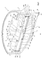
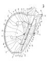
- the figures 2 and 3 are perspective views with section of the lower part 5 of the furnace, and respectively correspond to the open and closed positions of the shutters.
- the figure 4 is a view similar to the figure 3 , in which some pieces of the figure 3 are not represented.
- the cut of Figures 2 to 4 was carried out according to a plan of symmetry of the furnace containing the axis ⁇ 1.
- the exchanger 27 is represented in figures 3 and 4 but not in figure 2 .
- the upper flaps 32a and 32b and the lower flap 34c are represented on the figures 2 and 3 .
- the lower flap 34d is not shown in these figures.
- the flaps 32a, 32b, 34c and 34d are all identical, and have for example a rectangular shape in plan view.
- Each flap 32a, 32b, 34c and 34d is associated with a support 41a, 41b, 41c, 41d respectively.
- the supports 41a to 41d are for example made of graphite.
- the supports 41a to 41d may be of a material different from that of the flaps 32a, 32b, 34c, 34d, for example a material more rigid than that of the flaps.
- the material constituting the supports 41a to 41d can be chosen so as to have a good resistance to temperature.
- the figure 4 illustrates more particularly the supports 41a to 41c, the flaps not being shown in this figure.
- Each support 41a to 41d corresponds to a flat plate arranged orthogonal to the axis ⁇ 1.
- Each support 41a to 41d comprises a pointed portion 42a to 42d directed towards the axis of the oven ⁇ 1 and which, in plan view, has the general shape of an isosceles triangle.
- the four supports 41a to 41d are at the same level.
- Each upper flap 32a and 32b is spaced apart from the associated support 41a and 41b by spacer elements.
- the spacer elements comprise a spacer 35a, 35b, which is located between the flap 32a, 32b and the associated support 41a, 41b, at the edge of the flap 32a, 32b furthest from the axis ⁇ 1.
- the spacer 35a, 35b is fixed to the upper flap 32a, 32b and to the support 41a, 41b associated by means not shown.
- Each spacer 35a and 35b has a thickness substantially identical to that of the flaps 34c and 34d.
- the spacer elements furthermore comprise, for each component 32a and 32b, a rod 45a and 45b, of axis parallel to the axis ⁇ 1, fixed at one end to the edge of the flap 32a, 32b closest to the axis ⁇ 1 and fixed at the end opposite to the pointed portion 42a, 42b of the support 41a, 41b associated.
- Each flap 34c, 34d comprises two openings 47c, 47d and 48c, 48d having the shape of a half-cylinder axis parallel to the axis ⁇ 1.
- each support 41a to 41d is associated a rail 51a to 51d, disposed under the support 41a to 41d corresponding, and fixed to the plate 37 covering the heat exchanger 27.
- the support 41a to 41d associated with each flap is adapted to slide on the rail 51a to 51d associated.
- the material constituting the supports 41a to 41d may be chosen to facilitate the sliding of the supports 41a to 41d on the associated rails 51a to 51d.
- the thermal shielding further comprises driving elements, located for the most part under the heat exchanger 27.
- the driving elements comprise a driving part 53.
- the driving part 53 comprises a center of symmetry situated on the furnace axis ⁇ 1.
- the drive part 53 comprises four arms 55a to 55d, the end of each arm 55a to 55d being connected to a support 41a to 41d, via a connecting rod 57a to 57d and a connecting piece 59a. at 59d.
- a support piece 50a to 50d is fixed under the support 41a to 41d associated, at the end of the support farthest from the furnace axis ⁇ 1.
- Each flap 32a, 32b, 34c, 34d and the associated support 41a to 41d are fixed to the support piece 50a to 50d by elements not shown.
- Each connecting piece 59a to 59d is fixed to the bearing piece 50a to 50d, substantially in the middle of the bearing piece 50a to 50d.
- Each connecting piece 59a to 59d has a cylindrical shape oriented in a direction parallel to the axis ⁇ 1.
- Each connecting rod 57a to 57d is connected to the connecting piece 59a to 59d associated by a hinge member 58a to 58d, and is connected to the end of the arm 55a to 55d associated with the drive piece 53 by a d 56a to 56d.
- Each connecting rod 57a to 57d is oriented in one direction orthogonal to the axis ⁇ 1.
- Each hinge member 56a to 56d and 58a to 58d may be a pivot connection about an axis parallel to the axis ⁇ 1.
- Guides 61a to 61d rectilinear are arranged under the assembly consisting of the drive part 53, the connecting rods 57a to 57d and the connecting pieces 59a to 59d.
- the guides 61a, 61b are oriented along a horizontal axis located in one of the furnace symmetry planes.
- the guides 61c, 61d are oriented along a horizontal axis located in the other plane of symmetry of the oven.
- a bearing system 62a-62d is provided on each guide 61a-61d.
- the guides 61a to 61d rest at their end closest to the axis ⁇ 1 on a support plate 66.
- the drive part 53 is furthermore fixed, at its central part, to a shaft 65 mounted free to rotate along the axis ⁇ 1 on the lower enclosure 3 of the furnace by bearings not shown.
- the shaft 65 is rotated about the axis ⁇ 1 by a motor 67.
- the motor shaft 67 is adapted to rotate about an axis ⁇ 2 parallel to the axis ⁇ 1. Toothed wheels 69 and 71 and a chain 68 make it possible to transmit the rotational movement of the motor 67 to the shaft 65.
- the motor 67 is adapted to drive the shaft 65 in rotation continuously or in successive stages.
- the angular position of the shaft 65 can be determined from motor control signals 67.
- Supports 75 for receiving the crucible 7 are further shown in the various figures.
- the figures 5 and 6 are views from above of the lower part 5 of the furnace, more particularly illustrating the four flaps 32a, 32b, 34c and 34d of the heat shield, respectively in the open and closed position.
- FIGS. 7 and 8 are top views of the lower part 5 of the oven corresponding to figures 5 and 6 , the flaps 32a, 32b, 34c and 34d not being shown.
- each lower flap 34c, 34d is positioned for the most part between each upper flap 32a, 32b and the associated support 41a, 41b.
- the upper flaps 32a and 32b on the one hand, and the lower flaps 34c and 34d on the other hand, are in contact with one another along an edge.
- the rod 45a associated with the upper flap 32a is inserted into the openings 47c and 47d of the lower flaps 34c and 34d respectively.
- the rod 45b associated with the upper flap 32b is inserted into the openings 48c and 48d of the lower flaps 34c and 34d respectively.
- the bottom of the crucible 7 is thus isolated from the heat exchanger 27.
- the flaps are provided so that they extend under the entire bottom of the crucible when in the closed position.
- the length of the flaps may be of the order of 1 m, and their width may be of the order of 50 cm.
- the two upper flaps 32a, 32b on the one hand, and the two lower flaps 34c, 34d on the other hand, are progressively separated from one another, and so simultaneously.
- the flaps 32a, 32b, 34c, 34d of the heat shield are in the open position, which corresponds to the figures 2 , 5 and 7 .
- the motor 67 drives the drive part 53 in rotation by a quarter turn around the axis ⁇ 1.
- the rotation of the part 53 causes the displacement of the rods 57a to 57d, which themselves cause the displacement of the carriages 63a to 63d.
- Each carriage 63a to 63d then slides on the associated guide 61a to 61d, away from the axis ⁇ 1.
- Each carriage 63a to 63d drives in translation the flap 32a, 32b, 34c, 34d and the associated support 41a to 41d, via the connecting piece 59a to 59d and the support piece 50a to 50d.
- Each support 41a to 41d slides on the associated rail 51a to 51d away from the axis ⁇ 1.
- the rotational movement of the driving part 53 is thus transformed into a simultaneous translation movement of each flap 32a, 32b, 34c, 34d, the translation directions of the upper flaps 32a, 32b on the one hand, and the lower flaps 34c, 34d on the other hand, being orthogonal.
- the surface of the bottom of the crucible 7 exposed to the heat exchanger 27 is thus increased from the center of the crucible 7 until the entire bottom of the crucible 7 is exposed to the heat exchanger 27.
- the motor 67 drives the driving part 53 in rotation by a quarter turn around the axis ⁇ 1, in the opposite direction to the direction of rotation used during from the previous passage from the closed position to the open position of the flaps.
- the rotation of the driving part 53 causes the displacement of the rods 57a to 57d, which themselves cause the displacement of the carriages 63a to 63d.
- Each carriage 63a to 63d then slides on the guide 61a to 61d associated, approaching the axis ⁇ 1.
- Each carriage 63a to 63d drives in translation the flap 32a, 32b, 34c, 34d and the associated support 41a to 41d, via the connecting piece 59a to 59d and the support piece 50a to 50d.
- Each support 41a to 41d slides on the associated rail 51a to 51d closer to the axis ⁇ 1.
- the two upper flaps 32a and 32b on the one hand, and the two lower flaps 34c and 34d, on the other hand, thus approach each other, and the axis ⁇ 1, until coming into contact with one another.
- a directed solidification furnace comprising a thermal shield as described above has several advantages.
- Another advantage lies in the fact that the motor control is particularly simple since the synchronization of the translational movements of the four flaps during the transition from the closed position to the open position and vice versa is ensured by an assembly of mechanical parts.
- Another advantage of such an oven lies in the control of the crystallization.
- the four flaps of the thermal shield are spaced apart from each other, and from the axis of the furnace.
- the crystallization of the molten silicon is initiated from the center of the crucible.
- the rotational speed of the motor 67 driving the driving part 53 can be chosen so that the upper flaps 32a, 32b on the one hand, and lower 34c, 34d on the other hand, part one on the other very slowly. This makes it possible to gradually increase the surface of the bottom of the crucible exposed to the heat exchanger. Better control of the crystalline structure of the silicon ingot is thus obtained.
- the gradual increase of the surface of the bottom of the crucible exposed to the heat exchanger, from the center of the crucible improves the control of the shape of the crystallization front.
- Such an oven is particularly well suited to the manufacture of multicrystalline silicon ingots containing large single crystals, that is to say, the manufacture of so-called "quasi-monocrystalline” silicon ingots (in English “monolike”).
- monocrystalline seeds are introduced into the bottom of the crucible at the same time as the silicon pieces, which are generally polycrystalline.
- the flaps are open before the monocrystalline seeds have completely melted with the silicon pieces.
- the crystallization of silicon is thus initiated from monocrystalline seeds.
- the gradual increase in the surface of the bottom of the crucible exposed to the heat exchanger, from the center of the crucible makes it possible to control the crystalline growth of the quasi-monocrystalline silicon ingot.
Landscapes
- Chemical & Material Sciences (AREA)
- Engineering & Computer Science (AREA)
- Crystallography & Structural Chemistry (AREA)
- Materials Engineering (AREA)
- Metallurgy (AREA)
- Organic Chemistry (AREA)
- Mechanical Engineering (AREA)
- General Engineering & Computer Science (AREA)
- Crystals, And After-Treatments Of Crystals (AREA)
Abstract
Description
La présente invention concerne un four de solidification dirigée de cristaux, et plus particulièrement un tel four permettant d'obtenir des lingots de silicium destinés à la fabrication de panneaux solaires photovoltaïques.The present invention relates to a directed solidification furnace of crystals, and more particularly to such an oven for obtaining silicon ingots for the manufacture of photovoltaic solar panels.
Le principe de fonctionnement d'un four de solidification dirigée de cristaux est le suivant. Des morceaux de silicium sont introduits dans un creuset en silice. Des éléments de chauffage disposés autour des parois latérales du creuset ou au-dessus du creuset et/ou sous le fond du creuset, permettent ensuite de chauffer le creuset pour faire fondre les morceaux de silicium. Une fois les morceaux de silicium fondus, le creuset est refroidi pour cristalliser le silicium fondu. Le refroidissement du creuset est assuré depuis le fond du creuset, par exemple par un échangeur thermique disposé sous le fond du creuset. La cristallisation du silicium fondu débute alors par le fond du creuset. La solidification est dite dirigée. L'échangeur thermique est par exemple une plaque, disposée sous les éléments de chauffage du fond du creuset et refroidie par circulation d'un fluide.The principle of operation of a directed solidification furnace of crystals is as follows. Silicon chips are introduced into a silica crucible. Heating elements arranged around the side walls of the crucible or above the crucible and / or under the bottom of the crucible, then heat the crucible to melt the silicon pieces. Once the pieces of silicon are melted, the crucible is cooled to crystallize the molten silicon. The cooling of the crucible is provided from the bottom of the crucible, for example by a heat exchanger disposed under the bottom of the crucible. The crystallization of the molten silicon then begins at the bottom of the crucible. Solidification is said to be directed. The heat exchanger is for example a plate disposed under the heating elements of the bottom of the crucible and cooled by circulation of a fluid.
Après fusion puis cristallisation, un lingot de silicium de structure cristalline différente de celle des morceaux de silicium introduits initialement dans le creuset est obtenu. Généralement, le creuset a une base carrée de l'ordre de 1 m de côté et de 50 cm de hauteur, et on obtient un lingot de silicium de l'ordre de 1 m de côté et de 30 cm de hauteur, destiné à être découpé en briques calibrées.After melting then crystallization, a silicon ingot with a different crystalline structure from that of the pieces of silicon initially introduced into the crucible is obtained. Generally, the crucible has a square base of the order of 1 m side and 50 cm high, and one obtains a silicon ingot of the order of 1 m side and 30 cm high, intended to be cut into calibrated bricks.
Afin de limiter la consommation d'énergie du four, il convient, pendant le chauffage et la fusion des morceaux de silicium, de prévoir un blindage thermique entre l'échangeur et les éléments de chauffage du fond du creuset.In order to limit the energy consumption of the furnace, it is appropriate, during heating and melting of the silicon pieces, to provide a thermal shielding between the exchanger and the heating elements of the bottom of the crucible.
Un exemple de blindage thermique pouvant être utilisé est un volet mobile. Pendant les phases de chauffage et de fusion, le volet est positionné entre les éléments de chauffage et l'échangeur thermique. Pour assurer une bonne isolation thermique, le volet est suffisamment grand de façon à s'étendre sous la totalité du fond du creuset. Le volet est ensuite retiré pour commencer la cristallisation. Il faut alors prévoir un système de dégagement complet du volet pour découvrir entièrement l'échangeur thermique.An example of a thermal shield that can be used is a movable flap. During the heating and melting phases, the flap is positioned between the heating elements and the heat exchanger. To ensure good thermal insulation, the flap is large enough to extend under the entire bottom of the crucible. The flap is then removed to begin crystallization. It is then necessary to provide a complete release system of the shutter to fully discover the heat exchanger.
Un premier inconvénient d'un four équipé d'un blindage thermique tel que celui décrit ci-dessus réside dans son encombrement plus important par rapport à un four sans blindage thermique.A first disadvantage of an oven equipped with a heat shield such as that described above lies in its larger size compared to a furnace without thermal shielding.
Un autre inconvénient est lié au fait que, lors du dégagement du volet, l'exposition du fond du creuset par rapport à l'échangeur thermique débute à partir d'un bord du fond du creuset. La cristallisation du silicium fondu tend alors à commencer par un des bords du creuset. Pour obtenir une cristallisation uniforme du silicium fondu, il convient alors de dégager le volet le plus rapidement possible. Toutefois, pour certaines applications, il est préférable d'augmenter progressivement la surface du fond du creuset exposée à l'échangeur thermique. Dans un four équipé d'un blindage thermique du type de celui décrit ci-dessus, ceci se ferait au détriment de la qualité de la cristallisation du silicium fondu.Another disadvantage is related to the fact that, during the release of the flap, the exposure of the bottom of the crucible relative to the heat exchanger starts from an edge of the bottom of the crucible. The crystallization of molten silicon then tends to begin with one of the edges of the crucible. To obtain uniform crystallization of the molten silicon, it is then necessary to release the shutter as quickly as possible. However, for certain applications, it is preferable to gradually increase the surface of the bottom of the crucible exposed to the heat exchanger. In an oven equipped with a shield thermal type of that described above, this would be to the detriment of the quality of the crystallization of molten silicon.
Il existe donc un besoin d'un four de solidification dirigée de cristaux équipé d'un blindage thermique palliant au moins en partie certains des inconvénients des fours équipés d'un blindage thermique du type de celui décrit ci-dessus.There is therefore a need for a crystalline directed solidification furnace equipped with thermal shielding at least partially overcoming some of the disadvantages of furnaces equipped with a thermal shield of the type described above.
Ainsi, un objet d'un mode de réalisation de la présente invention est de prévoir un four de solidification dirigée de cristaux équipé d'un blindage thermique présentant un encombrement réduit.Thus, an object of an embodiment of the present invention is to provide a directed solidification furnace of crystals equipped with a thermal shield having a small footprint.
Un autre objet d'un mode de réalisation de la présente invention est de prévoir un four de solidification dirigée de cristaux équipé d'un blindage thermique permettant, pendant les phases de cristallisation, d'augmenter la surface du fond du creuset exposée à l'échangeur thermique à partir du centre du creuset.Another object of an embodiment of the present invention is to provide a crystalline directed solidification furnace equipped with a thermal shielding, during the crystallization phases, to increase the surface of the bottom of the crucible exposed to the heat exchanger from the center of the crucible.
Un autre objet d'un mode de réalisation de la présente invention est de prévoir un four de solidification dirigée de cristaux équipé d'un blindage thermique permettant, pendant les phases de cristallisation, d'augmenter progressivement la surface du fond du creuset exposée à l'échangeur thermique.Another object of an embodiment of the present invention is to provide a crystalline directed solidification furnace equipped with a thermal shielding, during the crystallization phases, to gradually increase the surface of the bottom of the crucible exposed to the 'heat exchanger.
Un mode de réalisation de la présente invention prévoit un four de solidification dirigée de cristaux comprenant un creuset, le creuset étant destiné à contenir les cristaux et comportant un axe de symétrie, le four comprenant successivement, selon l'axe de symétrie : le creuset ; des éléments de chauffage ; un blindage thermique ; un échangeur thermique ; le blindage thermique comprenant successivement, selon l'axe de symétrie, deux premiers volets et deux seconds volets, les premiers volets pouvant s'écarter et se rapprocher l'un de l'autre et de l'axe de symétrie par des mouvements de translation, et les seconds volets pouvant s'écarter et se rapprocher l'un de l'autre et de l'axe de symétrie par des mouvements de translation, les directions de translation des premiers volets et des seconds volets étant orthogonales.One embodiment of the present invention provides a directed solidification furnace of crystals comprising a crucible, the crucible being intended to contain the crystals and having an axis of symmetry, the furnace successively comprising, along the axis of symmetry: the crucible; heating elements; thermal shielding; a heat exchanger; the thermal shielding successively comprising, according to the axis of symmetry, two first flaps and two second flaps, the first flaps being able to deviate and approach one another and the axis of symmetry by translational movements , and the second flaps that can move away from each other and closer to each other and the axis of symmetry by translation movements, the translation directions of the first flaps and second flaps being orthogonal.
Selon un mode de réalisation de la présente invention, le blindage thermique comprend des supports, chaque premier et second volet étant fixé sur un support, les supports étant adaptés à coulisser sur une plaque disposée entre les volets et l'échangeur thermique.According to one embodiment of the present invention, the thermal shielding comprises supports, each first and second flap being fixed on a support, the supports being adapted to slide on a plate disposed between the flaps and the heat exchanger.
Selon un mode de réalisation de la présente invention, lorsque les premiers volets sont rapprochés au maximum l'un de l'autre et les seconds volets sont rapprochés au maximum l'un de l'autre, chaque second volet est positionné au moins en partie entre chaque premier volet et le support associé.According to one embodiment of the present invention, when the first flaps are brought closer to the maximum of each other and the second flaps are brought closer to each other, each second flap is positioned at least in part between each first component and the associated medium.
Selon un mode de réalisation de la présente invention, chaque premier et second volet a une forme rectangulaire et chaque support comprend une portion pointue dirigée vers l'axe de symétrie.According to an embodiment of the present invention, each first and second shutter has a rectangular shape and each support comprises a pointed portion directed towards the axis of symmetry.
Selon un mode de réalisation de la présente invention, les premiers volets sont adaptés à venir en contact l'un de l'autre et les seconds volets sont adaptés à venir en contact l'un de l'autre, et un côté de la portion pointue de l'un des supports associés aux premiers volets est adapté à venir en contact avec un côté de la portion pointue de l'un des supports associés aux seconds volets.According to one embodiment of the present invention, the first flaps are adapted to come into contact with each other and the second flaps are adapted to come into contact with one another, and one side of the portion pointed one of the supports associated with the first flaps is adapted to come into contact with one side of the pointed portion of one of the supports associated with the second flaps.
Selon un mode de réalisation de la présente invention, chaque premier volet est écarté du support associé, d'une distance égale à l'épaisseur de l'un des seconds volets, par des éléments d'écartement.According to an embodiment of the present invention, each first flap is spaced apart from the associated support, by a distance equal to the thickness of one of the second flaps, by spacer elements.
Selon un mode de réalisation de la présente invention, pour chaque premier volet, les éléments d'écartement comprennent une entretoise reliant le bord du premier volet le plus éloigné de l'axe de symétrie et le support associé, et une tige reliant le bord du premier volet le plus proche de l'axe de symétrie et la portion pointue du support associé, et chaque second volet comprend des ouvertures adaptées à recevoir les tiges lorsque les volets sont rapprochés au maximum l'un de l'autre.According to an embodiment of the present invention, for each first flap, the spacer elements comprise a spacer connecting the edge of the first flap furthest from the axis of symmetry and the associated support, and a rod connecting the edge of the flange. first flap closest to the axis of symmetry and the pointed portion of the associated support, and each second flap comprises apertures adapted to receive the rods when the flaps are brought closer to the maximum of one another.
Selon un mode de réalisation de la présente invention, le blindage thermique comprend un système d'entraînement adapté à écarter et rapprocher les premiers et seconds volets, l'échangeur thermique étant disposé entre les premiers et seconds volets d'une part et au moins une partie du système d'entraînement d'autre part.According to one embodiment of the present invention, the thermal shielding comprises a drive system adapted to separate and bring the first and second shutters, the heat exchanger being disposed between the first and second shutters on the one hand and at least one part of the drive system on the other hand.
Selon un mode de réalisation de la présente invention, le système d'entraînement comprend une pièce d'entraînement reliée à chaque premier et second volet par l'intermédiaire d'une bielle articulée par rapport à la pièce d'entraînement et par rapport au premier ou second volet associé, le système d'entraînement comprenant en outre un moteur adapté à entraîner la pièce d'entraînement en rotation autour de l'axe de symétrie.According to one embodiment of the present invention, the drive system comprises a drive part connected to each first and second flap via a rod articulated relative to the drive part and relative to the first one. or second associated flap, the drive system further comprising a motor adapted to drive the driving part in rotation about the axis of symmetry.
Selon un mode de réalisation de la présente invention, ce four comprend en outre, pour chaque premier et second volet, une pièce de liaison allongée fixée au bord du premier ou second volet associé le plus éloigné de l'axe de symétrie, la pièce de liaison allongée étant orientée suivant une direction parallèle à l'axe de symétrie, et la bielle étant articulée par rapport à la pièce de liaison et par rapport à la pièce d'entraînement et orientée suivant une direction orthogonale à l'axe de symétrie.According to an embodiment of the present invention, this furnace further comprises, for each first and second flap, an elongated connecting piece fixed to the edge of the first or second associated flap farthest from the axis of symmetry, the piece of elongate connection being oriented in a direction parallel to the axis of symmetry, and the rod being articulated relative to the connecting piece and relative to the drive part and oriented in a direction orthogonal to the axis of symmetry.
Un mode de réalisation de la présente invention prévoit en outre un procédé de fabrication d'un lingot d'un matériau cristallin, mettant en oeuvre le four décrit ci-dessus, comprenant les étapes suivantes : a) introduire des morceaux du matériau dans le creuset ; b) faire fondre les morceaux du matériau par les éléments de chauffage, les premiers volets étant rapprochés au maximum l'un de l'autre et les seconds volets étant rapprochés au maximum l'un de l'autre ; c) refroidir le matériau fondu par l'échangeur thermique en écartant les premiers volets l'un de l'autre et les seconds volets l'un de l'autre, pour amener le matériau fondu à se solidifier et former le lingot.An embodiment of the present invention further provides a method of manufacturing an ingot of a crystalline material, employing the oven described above, comprising the following steps: a) introducing pieces of the material into the crucible ; b) melting the pieces of material by the heating elements, the first flaps being brought closer to each other and the second flaps being brought closer to each other; c) cooling the melted material by the heat exchanger by removing the first flaps from each other and the second flaps one from the other, to cause the molten material to solidify and form the ingot.
Selon un mode de réalisation de la présente invention : à l'étape a), des germes monocristallins sont introduits dans le creuset en plus des morceaux du matériau, au moins une partie des germes monocristallins ne fondant pas à l'étape b); et à l'étape c), la solidification du matériau fondu est amorcée à partir de la partie des germes monocristallins qui n'a pas fondu à l'étape b).According to one embodiment of the present invention: in step a), monocrystalline seeds are introduced into the crucible in addition to pieces of the material, at least part of the monocrystalline seeds not melting in step b); and in step c), the solidification of the molten material is initiated from the monocrystalline seed portion which has not melted in step b).
Ces objets, caractéristiques et avantages, ainsi que d'autres seront exposés en détail dans la description suivante de modes de réalisation particuliers faite à titre non-limitatif en relation avec les figures jointes parmi lesquelles :
- la
figure 1 est une vue en coupe illustrant de façon schématique un four de solidification dirigée de cristaux comprenant un blindage thermique ; - les
figures 2 et3 sont des vues en perspective avec coupe de la partie inférieure du four illustré enfigure 1 lorsque le blindage thermique est respectivement en position ouverte et fermée ; - la
figure 4 est une vue analogue à lafigure 3 , certains éléments de lafigure 3 n'étant pas représentés ; - les
figures 5 et6 sont des vues de dessus de la partie inférieure du four illustré enfigure 1 lorsque le blindage thermique est respectivement en position ouverte et fermée ; et - les
figures 7 et8 sont des vues analogues respectivement auxfigures 5 et6 , dans lesquelles certains éléments desfigures 5 et6 ne sont pas représentés.
- the
figure 1 is a sectional view schematically illustrating a directed solidification furnace of crystals comprising a heat shield; - the
figures 2 and3 are perspective views with sectional view of the bottom of the oven shown infigure 1 when the thermal shield is respectively in the open and closed position; - the
figure 4 is a view similar to thefigure 3 , some elements of thefigure 3 not being represented; - the
figures 5 and6 are top views of the bottom of the oven shown infigure 1 when the thermal shield is respectively in the open and closed position; and - the
figures 7 and8 are similar views respectively tofigures 5 and6 , in which certain elements offigures 5 and6 are not represented.
Par souci de clarté, de mêmes éléments ont été désignés par de mêmes références dans les différentes figures. En outre, seuls les éléments nécessaires à la compréhension de l'invention ont été décrits.For the sake of clarity, the same elements have been designated by the same references in the various figures. In addition, only the elements necessary for understanding the invention have been described.
La
Le four comprend une enceinte 1, par exemple une enceinte cylindrique à double paroi d'axe Δ1, par exemple vertical. Dans la suite de la description, les adjectifs "supérieur" et "inférieur" sont utilisés en relation avec l'axe Δ1. Le plan de coupe correspond à un plan de symétrie contenant l'axe Δ1. Le diamètre extérieur de l'enceinte 1 est par exemple de 2 mètres. L'enceinte 1 est généralement refroidie par un système de mise en circulation d'un fluide, non représenté. L'enceinte 1 comprend une enceinte supérieure 2 et une enceinte inférieure 3, délimitant respectivement une partie supérieure 4 du four et une partie inférieure 5 du four.The furnace comprises an
En fonctionnement, la partie supérieure 4 du four comprend un creuset 7, par exemple en silice. Le creuset est par exemple de base carrée, par exemple de 88 cm de côté et de 42 cm de hauteur. Des plaques 9 sont fixées aux parois latérales et au fond du creuset 7. Les plaques 9 servent notamment à augmenter la rigidité du creuset 7. La plaque 9 sur laquelle repose le fond du creuset 7 est elle-même posée sur un support 11. Une plaque 13 recouvre le haut du creuset 7. Les plaques 9 et 13 et le support 11 sont en un matériau conducteur thermique, par exemple en graphite.In operation, the upper part 4 of the furnace comprises a
Des éléments de chauffage 15 sont disposés autour des plaques 9 entourant les parois latérales du creuset 7, et un élément de chauffage 17 est disposé au-dessus de la plaque 13 recouvrant le creuset 7. Des éléments isolants 19 entourent l'ensemble constitué par le creuset 7, les plaques 9 et 13, les éléments de chauffage 15 et 17, et le support 11.
Des éléments de chauffage 21 sont disposés sous le support 11, dans la partie inférieure 5 du four. Les éléments de chauffage 15, 17 et 21 sont par exemple constitués de résistances électriques comprenant par exemple plusieurs barreaux de chauffage.
Des éléments isolants 23 sont placés dans la partie inférieure 5 du four et délimitent avec les éléments isolants 19 une enceinte interne entourant le creuset 7 et comportant une ouverture 25 sous les éléments de chauffage 21.Insulating
Un échangeur thermique 27 est disposé sous les éléments de chauffage 21. L'échangeur thermique 27 est par exemple une plaque refroidie par circulation d'un fluide. L'échangeur thermique 27 peut aussi correspondre à une portion de l'enceinte inférieure 3.A
Le four comprend un blindage thermique 29, disposé entre les éléments de chauffage 21 et l'échangeur thermique 27, et comprenant deux volets supérieurs 32a et 32b, et deux volets inférieurs 34c et 34d (seul le volet 34c étant visible en
Les deux volets supérieurs 32a et 32b sont disposés sous les éléments de chauffage 21. Les deux volets inférieurs 34c et 34d sont disposés sous les volets 32a et 32b. Les volets 32a, 32b, 34c et 34d sont en un matériau isolant thermique, par exemple en feutre de graphite. Les volets 32a, 32b, 34c et 34d sont disposés orthogonalement à l'axe Δ1. Les volets supérieurs 32a, 32b peuvent être éloignés ou rapprochés l'un de l'autre par un mouvement de translation selon une direction orthogonale à l'axe Δ1 et contenue dans le plan de coupe (doubles flèches 31). Les volets inférieurs 34c, 34d peuvent être éloignés ou rapprochés l'un de l'autre par un mouvement de translation selon une direction orthogonale à l'axe Δ1 et perpendiculaire au plan de coupe (double flèche 33). Une plaque 37, en un matériau conducteur thermique, par exemple en graphite, recouvre l'échangeur 27.The two
Le four comprend en outre un conduit 39 destiné à l'injection d'un gaz inerte, par exemple de l'argon, à l'intérieur de l'enceinte 1 du four.The oven further comprises a
Le fonctionnement d'un tel four de solidification dirigée de cristaux est le suivant.The operation of such a directed crystal solidification furnace is as follows.
La partie inférieure 5 du four est éloignée de la partie supérieure 4 du four. Le creuset 7 contenant des morceaux de silicium est mis en place dans le four. L'enceinte 1 du four est ensuite refermée en rapprochant la partie inférieure 5 de la partie supérieure 4 du four.The
Afin de faire fondre les morceaux de silicium contenus dans le creuset 7, une température supérieure à la température de fusion du silicium (environ 1420°C), par exemple une température de l'ordre de 1500°C, est appliquée dans le creuset 7 par les éléments de chauffage 15, 17 et 21. Les phases de chauffage et de fusion du silicium peuvent durer par exemple environ 12 heures.In order to melt the silicon pieces contained in the
Pendant les phases de chauffage et de fusion du silicium, les volets 32a, 32b, 34c et 34d sont positionnés entre les éléments de chauffage 21 et l'échangeur thermique 27, de façon à fermer l'ouverture 25. Les pertes thermiques lors du chauffage du creuset 7 sont ainsi réduites. Dans la suite de la description, les volets 32a, 32b, 34c et 34d sont alors dits en position fermée.During the heating and melting phases of the silicon, the
Une fois les morceaux de silicium fondus, les éléments de chauffage 21 sont arrêtés. Les volets 32a, 32b, 34c et 34d sont dégagés pour découvrir l'ouverture 25. Dans la suite de la description, les volets 32a, 32b, 34c et 34d sont alors dits en position ouverte. Le fond du creuset 7 est refroidi par l'échangeur thermique 27. La phase de cristallisation du silicium peut durer environ 24 heures, et la vitesse de cristallisation du silicium est par exemple de quelques millimètres par heure. Pendant toute la phase de cristallisation, la température est maintenue à environ 1420°C au sommet du creuset 7.Once the pieces of silicon have melted, the
Un exemple de réalisation d'un blindage thermique tel que celui décrit en relation avec la
Les
Les volets supérieurs 32a et 32b et le volet inférieur 34c sont représentés sur les
Chaque volet supérieur 32a et 32b est écarté du support associé 41a et 41b par des éléments d'écartement. Les éléments d'écartement comprennent une entretoise 35a, 35b, qui est située entre le volet 32a, 32b et le support 41a, 41b associé, au niveau du bord du volet 32a, 32b le plus éloigné de l'axe Δ1. L'entretoise 35a, 35b est fixée au volet supérieur 32a, 32b et au support 41a, 41b associé par des moyens non représentés. Chaque entretoise 35a et 35b a une épaisseur sensiblement identique à celle des volets 34c et 34d. Les éléments d'écartement comprennent en outre, pour chaque volet 32a et 32b, une tige 45a et 45b, d'axe parallèle à l'axe Δ1, fixée à une extrémité au bord du volet 32a, 32b le plus proche de l'axe Δ1 et fixée à l'extrémité opposée à la portion pointue 42a, 42b du support 41a, 41b associé. Chaque volet 34c, 34d comprend deux ouvertures 47c, 47d et 48c, 48d ayant la forme d'un demi-cylindre d'axe parallèle à l'axe Δ1.Each
A chaque support 41a à 41d est associé un rail 51a à 51d, disposé sous le support 41a à 41d correspondant, et fixé à la plaque 37 recouvrant l'échangeur thermique 27. Le support 41a à 41d associé à chaque volet est adapté à coulisser sur le rail 51a à 51d associé. Le matériau constituant les supports 41a à 41d peut être choisi pour faciliter le coulissement des supports 41a à 41d sur les rails 51a à 51d associés.To each
Le blindage thermique comprend en outre des éléments d'entraînement, situés pour la majeure partie sous l'échangeur thermique 27. Les éléments d'entraînement comprennent une pièce d'entraînement 53. La pièce d'entraînement 53 comprend un centre de symétrie situé sur l'axe du four Δ1. La pièce d'entraînement 53 comprend quatre bras 55a à 55d, l'extrémité de chaque bras 55a à 55d étant reliée à un support 41a à 41d, par l'intermédiaire d'une bielle 57a à 57d et d'une pièce de liaison 59a à 59d. Pour chaque volet 32a, 32b, 34c, 34d, une pièce d'appui 50a à 50d est fixée sous le support 41a à 41d associé, au niveau de l'extrémité du support le plus éloigné de l'axe du four Δ1. Chaque volet 32a, 32b, 34c, 34d et le support associé 41a à 41d sont fixés à la pièce d'appui 50a à 50d par des éléments non représentés. Chaque pièce de liaison 59a à 59d est fixée à la pièce d'appui 50a à 50d, sensiblement au milieu de la pièce d'appui 50a à 50d. Chaque pièce de liaison 59a à 59d a une forme cylindrique orientée suivant une direction parallèle à l'axe Δ1. Chaque bielle 57a à 57d est reliée à la pièce de liaison 59a à 59d associée par un élément d'articulation 58a à 58d, et est reliée à l'extrémité du bras 55a à 55d associé de la pièce d'entraînement 53 par un élément d'articulation 56a à 56d. Chaque bielle 57a à 57d est orientée suivant une direction orthogonale à l'axe Δ1. Chaque élément d'articulation 56a à 56d et 58a à 58d peut être une liaison à pivot autour d'un axe parallèle à l'axe Δ1. Des guides 61a à 61d rectilignes sont disposés sous l'ensemble constitué par la pièce d'entraînement 53, les bielles 57a à 57d et les pièces de liaison 59a à 59d. Les guides 61a, 61b sont orientés selon un axe horizontal situé dans l'un des plans de symétrie du four. Les guides 61c, 61d sont orientés selon un axe horizontal situé dans l'autre plan de symétrie du four. Un système à roulements 62a à 62d est prévu sur chaque guide 61a à 61d. L'extrémité de chaque pièce de liaison 59a à 59d, qui n'est pas fixée à la pièce d'appui 50a à 50d associée, est fixée à un chariot 63a à 63d adapté à coulisser sur le système à roulements 62a à 62d correspondant. Les guides 61a à 61d reposent au niveau de leur extrémité la plus proche de l'axe Δ1 sur une plaque d'appui 66.The thermal shielding further comprises driving elements, located for the most part under the
La pièce d'entraînement 53 est en outre fixée, au niveau de sa partie centrale, à un arbre 65 monté libre en rotation selon l'axe Δ1 sur l'enceinte inférieure 3 du four par des paliers non représentés. L'arbre 65 est entraîné en rotation autour de l'axe Δ1 par un moteur 67. L'arbre du moteur 67 est adapté à tourner autour d'un axe Δ2 parallèle à l'axe Δ1. Des roues dentées 69 et 71 et une chaîne 68 permettent de transmettre le mouvement de rotation du moteur 67 à l'arbre 65. Le moteur 67 est adapté à entraîner en rotation l'arbre 65 de façon continue ou par paliers successifs. La position angulaire de l'arbre 65 peut être déterminée à partir de signaux de commande du moteur 67.The
Des supports 75 destinés à recevoir le creuset 7 sont en outre représentés sur les différentes figures.
Les
Les
Le fonctionnement d'un blindage thermique du type de celui décrit en relation avec les
Pendant les phases de chauffage et de fusion du silicium contenu dans le creuset 7, les volets du blindage thermique sont en position fermée, ce qui correspond aux
Pour assurer une bonne isolation thermique, des dimensions suffisantes des volets sont prévues de façon qu'ils s'étendent sous la totalité du fond du creuset lorsqu'ils sont en position fermée. A titre d'exemple, pour un creuset de base carrée de 90 cm de côté, la longueur des volets peut être de l'ordre de 1 m, et leur largeur peut être de l'ordre de 50 cm.To ensure good thermal insulation, sufficient dimensions of the flaps are provided so that they extend under the entire bottom of the crucible when in the closed position. For example, for a square base crucible of 90 cm side, the length of the flaps may be of the order of 1 m, and their width may be of the order of 50 cm.
Une fois les phases de chauffage et de fusion terminées, les deux volets supérieurs 32a, 32b d'une part, et les deux volets inférieurs 34c, 34d d'autre part, sont écartés progressivement l'un de l'autre, et de façon simultanée. Une fois écartés au maximum, les volets 32a, 32b, 34c, 34d du blindage thermique sont en position ouverte, ce qui correspond aux
Pour passer de la position fermée des volets à la position ouverte, le moteur 67 entraîne la pièce d'entraînement 53 en rotation d'un quart de tour autour de l'axe Δ1. La rotation de la pièce 53 entraîne le déplacement des bielles 57a à 57d, qui elles-mêmes entraînent le déplacement des chariots 63a à 63d. Chaque chariot 63a à 63d coulisse alors sur le guide 61a à 61d associé, en s'éloignant de l'axe Δ1. Chaque chariot 63a à 63d entraîne en translation le volet 32a, 32b, 34c, 34d et le support associé 41a à 41d, par l'intermédiaire de la pièce de liaison 59a à 59d et de la pièce d'appui 50a à 50d. Chaque support 41a à 41d coulisse sur le rail 51a à 51d associé en s'éloignant de l'axe Δ1. Les deux volets supérieurs 32a, 32b d'une part, et les deux volets inférieurs 34c et 34d d'autre part, s'écartent ainsi l'un de l'autre, et de l'axe Δ1. Le mouvement de rotation de la pièce d'entraînement 53 est donc transformé en un mouvement de translation simultané de chaque volet 32a, 32b, 34c, 34d, les directions de translation des volets supérieurs 32a, 32b d'une part, et des volets inférieurs 34c, 34d d'autre part, étant orthogonales. La surface du fond du creuset 7 exposée à l'échangeur thermique 27 est ainsi augmentée à partir du centre du creuset 7 jusqu'à ce que la totalité du fond du creuset 7 soit exposée à l'échangeur thermique 27.To move from the closed position of the flaps to the open position, the
Pour passer de la position ouverte des volets à la position fermée, le moteur 67 entraîne la pièce d'entraînement 53 en rotation d'un quart de tour autour de l'axe Δ1, dans le sens inverse par rapport au sens de rotation utilisé lors du passage précédent de la position fermée à la position ouverte des volets. La rotation de la pièce d'entraînement 53 entraîne le déplacement des bielles 57a à 57d, qui elles-mêmes entraînent le déplacement des chariots 63a à 63d. Chaque chariot 63a à 63d coulisse alors sur le guide 61a à 61d associé, en se rapprochant de l'axe Δ1. Chaque chariot 63a à 63d entraîne en translation le volet 32a, 32b, 34c, 34d et le support associé 41a à 41d, par l'intermédiaire de la pièce de liaison 59a à 59d et de la pièce d'appui 50a à 50d. Chaque support 41a à 41d coulisse sur le rail 51a à 51d associé en se rapprochant de l'axe Δ1. Les deux volets supérieurs 32a et 32b d'une part, et les deux volets inférieurs 34c et 34d d'autre part, se rapprochent ainsi l'un de l'autre, et de l'axe Δ1, jusqu'à venir en contact l'un de l'autre.To move from the open position of the flaps to the closed position, the
Un four de solidification dirigée comprenant un blindage thermique tel que celui décrit ci-dessus présente plusieurs avantages.A directed solidification furnace comprising a thermal shield as described above has several advantages.
Un avantage réside dans l'encombrement réduit d'un tel four. Les quatre volets, chacun ayant une aire légèrement supérieure à la moitié de l'aire du fond du creuset, peuvent être écartés simultanément pour découvrir entièrement l'échangeur thermique, tout en entraînant un encombrement inférieur à celui qui serait nécessaire avec un volet unique se dégageant latéralement. De plus, le système d'entraînement du blindage thermique lui-même présente un encombrement réduit. En effet, il est situé pour sa majeure partie sous l'échangeur thermique. De plus, il permet le pilotage centralisé des quatre volets du blindage thermique par un seul moteur.An advantage lies in the reduced size of such an oven. The four flaps, each having an area slightly greater than half the area of the bottom of the crucible, can be discarded simultaneously to fully discover the heat exchanger, while resulting in a smaller footprint than would be necessary with a single flap. clearing laterally. In addition, the drive system of the thermal shield itself has a small footprint. Indeed, it is located for the most part under the heat exchanger. In addition, it allows the central control of the four shutters of the thermal shielding by a single motor.
Un autre avantage réside dans le fait que la commande du moteur est particulièrement simple puisque la synchronisation des mouvements de translation des quatre volets lors du passage de la position fermée à la position ouverte et inversement est assurée par un assemblage de pièces mécaniques.Another advantage lies in the fact that the motor control is particularly simple since the synchronization of the translational movements of the four flaps during the transition from the closed position to the open position and vice versa is ensured by an assembly of mechanical parts.
Un autre avantage d'un tel four réside dans le contrôle de la cristallisation. Pendant les phases de cristallisation, les quatre volets du blindage thermique sont écartés simultanément l'un de l'autre, et à partir de l'axe du four. Ainsi, la cristallisation du silicium fondu est amorcée à partir du centre du creuset. Ceci permet d'améliorer la cristallisation pour des applications photovoltaïques. De plus, la vitesse de rotation du moteur 67 entraînant la pièce d'entraînement 53 peut être choisie de façon que les volets supérieurs 32a, 32b d'une part, et inférieurs 34c, 34d d'autre part, s'écartent l'un de l'autre très lentement. Ceci permet d'augmenter progressivement la surface du fond du creuset exposée à l'échangeur thermique. Un meilleur contrôle de la structure cristalline du lingot de silicium est ainsi obtenu. L'augmentation progressive de la surface du fond du creuset exposée à l'échangeur thermique, à partir du centre du creuset, permet d'améliorer le contrôle de la forme du front de cristallisation.Another advantage of such an oven lies in the control of the crystallization. During the crystallization phases, the four flaps of the thermal shield are spaced apart from each other, and from the axis of the furnace. Thus, the crystallization of the molten silicon is initiated from the center of the crucible. This makes it possible to improve the crystallization for photovoltaic applications. In addition, the rotational speed of the
Un tel four est particulièrement bien adapté à la fabrication de lingots de silicium multicristallins contenant des monocristaux de taille importante, c'est-à-dire à la fabrication de lingots de silicium dits "quasi-monocristallins" (en anglais "monolike"). Dans ce cas, des germes monocristallins sont introduits dans le fond du creuset en même temps que les morceaux de silicium, qui sont généralement polycristallins. Les volets sont ouverts avant que les germes monocristallins aient entièrement fondu avec les morceaux de silicium. La cristallisation du silicium est ainsi amorcée à partir des germes monocristallins. L'augmentation progressive de la surface du fond du creuset exposée à l'échangeur thermique, à partir du centre du creuset, permet de maîtriser la croissance cristalline du lingot de silicium quasi-monocristallin.Such an oven is particularly well suited to the manufacture of multicrystalline silicon ingots containing large single crystals, that is to say, the manufacture of so-called "quasi-monocrystalline" silicon ingots (in English "monolike"). In this case, monocrystalline seeds are introduced into the bottom of the crucible at the same time as the silicon pieces, which are generally polycrystalline. The flaps are open before the monocrystalline seeds have completely melted with the silicon pieces. The crystallization of silicon is thus initiated from monocrystalline seeds. The gradual increase in the surface of the bottom of the crucible exposed to the heat exchanger, from the center of the crucible, makes it possible to control the crystalline growth of the quasi-monocrystalline silicon ingot.
Des modes de réalisation particuliers de la présente invention ont été décrits. Diverses variantes et modifications apparaîtront à l'homme de l'art. En particulier, bien qu'on ait décrit ci-dessus le fonctionnement d'un four de solidification dirigée de cristaux dans le cas particulier de cristaux de silicium, un four de solidification dirigée de cristaux tel que celui décrit en relation avec les
Claims (12)
Applications Claiming Priority (1)
| Application Number | Priority Date | Filing Date | Title |
|---|---|---|---|
| FR1158702A FR2980489B1 (en) | 2011-09-28 | 2011-09-28 | CRYSTAL DIRECTED SOLIDIFICATION OVEN |
Publications (2)
| Publication Number | Publication Date |
|---|---|
| EP2574689A1 true EP2574689A1 (en) | 2013-04-03 |
| EP2574689B1 EP2574689B1 (en) | 2019-02-27 |
Family
ID=46851896
Family Applications (1)
| Application Number | Title | Priority Date | Filing Date |
|---|---|---|---|
| EP12185910.2A Active EP2574689B1 (en) | 2011-09-28 | 2012-09-25 | Furnace for directional solidification of crystals |
Country Status (4)
| Country | Link |
|---|---|
| EP (1) | EP2574689B1 (en) |
| CN (1) | CN103031594A (en) |
| FR (1) | FR2980489B1 (en) |
| TW (1) | TWI563131B (en) |
Cited By (4)
| Publication number | Priority date | Publication date | Assignee | Title |
|---|---|---|---|---|
| EP3066235B1 (en) * | 2013-11-07 | 2019-05-01 | EBNER Industrieofenbau GmbH | Controlling a temperature of a crucible inside an oven |
| AT524602A1 (en) * | 2020-12-29 | 2022-07-15 | Fametec Gmbh | Apparatus for producing a single crystal |
| AT524600A1 (en) * | 2020-12-29 | 2022-07-15 | Fametec Gmbh | Process for producing a monocrystalline crystal, in particular a sapphire |
| AT524601A1 (en) * | 2020-12-29 | 2022-07-15 | Fametec Gmbh | Device for growing an artificially produced single crystal, in particular a sapphire single crystal |
Citations (4)
| Publication number | Priority date | Publication date | Assignee | Title |
|---|---|---|---|---|
| US20090090296A1 (en) * | 2007-10-05 | 2009-04-09 | Jong-Won Gil | Apparatus for manufacturing poly crystaline silicon ingot for solar battery having door open/close device using hinge |
| US20090280050A1 (en) * | 2008-04-25 | 2009-11-12 | Applied Materials, Inc. | Apparatus and Methods for Casting Multi-Crystalline Silicon Ingots |
| WO2011037343A2 (en) * | 2009-09-24 | 2011-03-31 | 주식회사 글로실 | Polycrystalline silicon ingot production device provided with a rotating door opening and shutting device |
| WO2011112926A1 (en) * | 2010-03-12 | 2011-09-15 | Gt Solar, Incorporated | Crystal growth apparatus with load-centered aperture, and device and method for controlling heat extraction from a crucible |
Family Cites Families (4)
| Publication number | Priority date | Publication date | Assignee | Title |
|---|---|---|---|---|
| JP3964070B2 (en) * | 1999-04-08 | 2007-08-22 | 三菱マテリアルテクノ株式会社 | Crystalline silicon production equipment |
| US7344596B2 (en) * | 2005-08-25 | 2008-03-18 | Crystal Systems, Inc. | System and method for crystal growing |
| CN201962406U (en) * | 2011-01-29 | 2011-09-07 | 大连隆田科技有限公司 | Bipartition tieplate type thermorytic smelting furnace for polycrystalline silicon ingot |
| CN102140672B (en) * | 2011-03-15 | 2012-12-26 | 杭州精功机电研究所有限公司 | Double-cavity thermal field of crystal silicon ingot casting furnace and control method thereof |
-
2011
- 2011-09-28 FR FR1158702A patent/FR2980489B1/en not_active Expired - Fee Related
-
2012
- 2012-09-25 CN CN2012103624597A patent/CN103031594A/en active Pending
- 2012-09-25 EP EP12185910.2A patent/EP2574689B1/en active Active
- 2012-09-27 TW TW101135514A patent/TWI563131B/en active
Patent Citations (4)
| Publication number | Priority date | Publication date | Assignee | Title |
|---|---|---|---|---|
| US20090090296A1 (en) * | 2007-10-05 | 2009-04-09 | Jong-Won Gil | Apparatus for manufacturing poly crystaline silicon ingot for solar battery having door open/close device using hinge |
| US20090280050A1 (en) * | 2008-04-25 | 2009-11-12 | Applied Materials, Inc. | Apparatus and Methods for Casting Multi-Crystalline Silicon Ingots |
| WO2011037343A2 (en) * | 2009-09-24 | 2011-03-31 | 주식회사 글로실 | Polycrystalline silicon ingot production device provided with a rotating door opening and shutting device |
| WO2011112926A1 (en) * | 2010-03-12 | 2011-09-15 | Gt Solar, Incorporated | Crystal growth apparatus with load-centered aperture, and device and method for controlling heat extraction from a crucible |
Cited By (7)
| Publication number | Priority date | Publication date | Assignee | Title |
|---|---|---|---|---|
| EP3066235B1 (en) * | 2013-11-07 | 2019-05-01 | EBNER Industrieofenbau GmbH | Controlling a temperature of a crucible inside an oven |
| AT524602A1 (en) * | 2020-12-29 | 2022-07-15 | Fametec Gmbh | Apparatus for producing a single crystal |
| AT524600A1 (en) * | 2020-12-29 | 2022-07-15 | Fametec Gmbh | Process for producing a monocrystalline crystal, in particular a sapphire |
| AT524601A1 (en) * | 2020-12-29 | 2022-07-15 | Fametec Gmbh | Device for growing an artificially produced single crystal, in particular a sapphire single crystal |
| AT524601B1 (en) * | 2020-12-29 | 2023-04-15 | Fametec Gmbh | Device for growing an artificially produced single crystal, in particular a sapphire single crystal |
| AT524602B1 (en) * | 2020-12-29 | 2023-05-15 | Fametec Gmbh | Apparatus for producing a single crystal |
| AT524600B1 (en) * | 2020-12-29 | 2023-05-15 | Fametec Gmbh | Process for producing a monocrystalline crystal, in particular a sapphire |
Also Published As
| Publication number | Publication date |
|---|---|
| CN103031594A (en) | 2013-04-10 |
| EP2574689B1 (en) | 2019-02-27 |
| FR2980489A1 (en) | 2013-03-29 |
| TWI563131B (en) | 2016-12-21 |
| FR2980489B1 (en) | 2014-09-19 |
| TW201313969A (en) | 2013-04-01 |
Similar Documents
| Publication | Publication Date | Title |
|---|---|---|
| EP2574689B1 (en) | Furnace for directional solidification of crystals | |
| EP2212197B1 (en) | Twin rotor flying vehicle | |
| EP3445601B1 (en) | Device for opening and closing of flaps | |
| EP2646604B1 (en) | Heat exchanger for a system for solidifying and/or crystallizing a semiconductor | |
| EP3004431A1 (en) | Method for producing a silicon ingot provided with symmetrical grain boundaries | |
| FR2634788A1 (en) | Apparatus for producing tubular crystalline bodies | |
| EP3774430A1 (en) | Device for controlling an air flow circulating in a heat exchanger for a motor vehicle and cooling module provided with such a device | |
| FR2688855A1 (en) | DEVICE INDICATOR OF THE POSITION OF A VALVE. | |
| EP3706934B1 (en) | Device and method for manufacturing a metal alloy blank by centrifugal casting | |
| CA3082924C (en) | Vehicle intended for an electrical line | |
| FR2966857A1 (en) | Basin covering device for bath assembly, has cover assembly carried by movable sub-assembly of support assembly so to be moved vertically relative to fixed sub-assembly during movement of movable sub-assembly relative to fixed sub-assembly | |
| EP0490727B1 (en) | Apparatus and crucible for vapor phase deposition | |
| FR2874340A1 (en) | Foundry method for fabricating jet engine blade, involves manufacturing shell whose additional part is arranged on another part, where additional part is plane and perpendicular to vertical axis of latter part | |
| JP6122193B1 (en) | Single crystal manufacturing apparatus and single crystal manufacturing method | |
| FR3081173A1 (en) | CRYSTAL DIRECTED SOLIDIFICATION OVEN | |
| JP5331626B2 (en) | Single crystal silicon manufacturing apparatus and single crystal silicon manufacturing method | |
| EP3475012B1 (en) | Directional solidification cooling furnace and cooling process using such a furnace | |
| EP0084482B1 (en) | Telescopic remote manipulator of the master-slave type and its balancing means | |
| FR2810342A1 (en) | CRYSTALLOGENESIS PROCESS WITH MAGNETIC FIELD | |
| EP2401949A1 (en) | Barbecue | |
| EP3727725B1 (en) | Crucible for directed solidifaction | |
| WO2024100122A1 (en) | Mechanism for moving a wire-deposition three-dimensional printing tool of an additive manufacturing machine | |
| FR2966858A1 (en) | Covering device for covering basin of bath assembly, has cover assembly including flaps, where assembly adopts unfolded flap configuration in which basin faces of flaps are oriented along same direction to be oriented in opening of basin | |
| EP3921462A1 (en) | Cold crucible | |
| FR2913714A1 (en) | STORE INTEGRABLE IN A DOUBLE GLAZING. |
Legal Events
| Date | Code | Title | Description |
|---|---|---|---|
| PUAI | Public reference made under article 153(3) epc to a published international application that has entered the european phase |
Free format text: ORIGINAL CODE: 0009012 |
|
| AK | Designated contracting states |
Kind code of ref document: A1 Designated state(s): AL AT BE BG CH CY CZ DE DK EE ES FI FR GB GR HR HU IE IS IT LI LT LU LV MC MK MT NL NO PL PT RO RS SE SI SK SM TR |
|
| AX | Request for extension of the european patent |
Extension state: BA ME |
|
| 17P | Request for examination filed |
Effective date: 20130905 |
|
| RBV | Designated contracting states (corrected) |
Designated state(s): AL AT BE BG CH CY CZ DE DK EE ES FI FR GB GR HR HU IE IS IT LI LT LU LV MC MK MT NL NO PL PT RO RS SE SI SK SM TR |
|
| STAA | Information on the status of an ep patent application or granted ep patent |
Free format text: STATUS: EXAMINATION IS IN PROGRESS |
|
| 17Q | First examination report despatched |
Effective date: 20170222 |
|
| GRAP | Despatch of communication of intention to grant a patent |
Free format text: ORIGINAL CODE: EPIDOSNIGR1 |
|
| STAA | Information on the status of an ep patent application or granted ep patent |
Free format text: STATUS: GRANT OF PATENT IS INTENDED |
|
| RIC1 | Information provided on ipc code assigned before grant |
Ipc: C30B 29/06 20060101ALI20180810BHEP Ipc: F27B 14/20 20060101ALI20180810BHEP Ipc: C30B 28/06 20060101ALI20180810BHEP Ipc: C30B 11/00 20060101AFI20180810BHEP Ipc: F27B 14/06 20060101ALI20180810BHEP Ipc: C30B 35/00 20060101ALI20180810BHEP |
|
| INTG | Intention to grant announced |
Effective date: 20180910 |
|
| GRAS | Grant fee paid |
Free format text: ORIGINAL CODE: EPIDOSNIGR3 |
|
| GRAA | (expected) grant |
Free format text: ORIGINAL CODE: 0009210 |
|
| STAA | Information on the status of an ep patent application or granted ep patent |
Free format text: STATUS: THE PATENT HAS BEEN GRANTED |
|
| AK | Designated contracting states |
Kind code of ref document: B1 Designated state(s): AL AT BE BG CH CY CZ DE DK EE ES FI FR GB GR HR HU IE IS IT LI LT LU LV MC MK MT NL NO PL PT RO RS SE SI SK SM TR |
|
| REG | Reference to a national code |
Ref country code: GB Ref legal event code: FG4D Free format text: NOT ENGLISH |
|
| REG | Reference to a national code |
Ref country code: CH Ref legal event code: EP |
|
| REG | Reference to a national code |
Ref country code: AT Ref legal event code: REF Ref document number: 1101462 Country of ref document: AT Kind code of ref document: T Effective date: 20190315 |
|
| REG | Reference to a national code |
Ref country code: IE Ref legal event code: FG4D Free format text: LANGUAGE OF EP DOCUMENT: FRENCH |
|
| REG | Reference to a national code |
Ref country code: DE Ref legal event code: R096 Ref document number: 602012057066 Country of ref document: DE |
|
| REG | Reference to a national code |
Ref country code: NL Ref legal event code: MP Effective date: 20190227 |
|
| REG | Reference to a national code |
Ref country code: LT Ref legal event code: MG4D |
|
| PG25 | Lapsed in a contracting state [announced via postgrant information from national office to epo] |
Ref country code: NO Free format text: LAPSE BECAUSE OF FAILURE TO SUBMIT A TRANSLATION OF THE DESCRIPTION OR TO PAY THE FEE WITHIN THE PRESCRIBED TIME-LIMIT Effective date: 20190527 Ref country code: SE Free format text: LAPSE BECAUSE OF FAILURE TO SUBMIT A TRANSLATION OF THE DESCRIPTION OR TO PAY THE FEE WITHIN THE PRESCRIBED TIME-LIMIT Effective date: 20190227 Ref country code: FI Free format text: LAPSE BECAUSE OF FAILURE TO SUBMIT A TRANSLATION OF THE DESCRIPTION OR TO PAY THE FEE WITHIN THE PRESCRIBED TIME-LIMIT Effective date: 20190227 Ref country code: PT Free format text: LAPSE BECAUSE OF FAILURE TO SUBMIT A TRANSLATION OF THE DESCRIPTION OR TO PAY THE FEE WITHIN THE PRESCRIBED TIME-LIMIT Effective date: 20190627 Ref country code: NL Free format text: LAPSE BECAUSE OF FAILURE TO SUBMIT A TRANSLATION OF THE DESCRIPTION OR TO PAY THE FEE WITHIN THE PRESCRIBED TIME-LIMIT Effective date: 20190227 Ref country code: LT Free format text: LAPSE BECAUSE OF FAILURE TO SUBMIT A TRANSLATION OF THE DESCRIPTION OR TO PAY THE FEE WITHIN THE PRESCRIBED TIME-LIMIT Effective date: 20190227 |
|
| PG25 | Lapsed in a contracting state [announced via postgrant information from national office to epo] |
Ref country code: LV Free format text: LAPSE BECAUSE OF FAILURE TO SUBMIT A TRANSLATION OF THE DESCRIPTION OR TO PAY THE FEE WITHIN THE PRESCRIBED TIME-LIMIT Effective date: 20190227 Ref country code: HR Free format text: LAPSE BECAUSE OF FAILURE TO SUBMIT A TRANSLATION OF THE DESCRIPTION OR TO PAY THE FEE WITHIN THE PRESCRIBED TIME-LIMIT Effective date: 20190227 Ref country code: GR Free format text: LAPSE BECAUSE OF FAILURE TO SUBMIT A TRANSLATION OF THE DESCRIPTION OR TO PAY THE FEE WITHIN THE PRESCRIBED TIME-LIMIT Effective date: 20190528 Ref country code: IS Free format text: LAPSE BECAUSE OF FAILURE TO SUBMIT A TRANSLATION OF THE DESCRIPTION OR TO PAY THE FEE WITHIN THE PRESCRIBED TIME-LIMIT Effective date: 20190627 Ref country code: BG Free format text: LAPSE BECAUSE OF FAILURE TO SUBMIT A TRANSLATION OF THE DESCRIPTION OR TO PAY THE FEE WITHIN THE PRESCRIBED TIME-LIMIT Effective date: 20190527 Ref country code: RS Free format text: LAPSE BECAUSE OF FAILURE TO SUBMIT A TRANSLATION OF THE DESCRIPTION OR TO PAY THE FEE WITHIN THE PRESCRIBED TIME-LIMIT Effective date: 20190227 |
|
| REG | Reference to a national code |
Ref country code: AT Ref legal event code: MK05 Ref document number: 1101462 Country of ref document: AT Kind code of ref document: T Effective date: 20190227 |
|
| PG25 | Lapsed in a contracting state [announced via postgrant information from national office to epo] |
Ref country code: AL Free format text: LAPSE BECAUSE OF FAILURE TO SUBMIT A TRANSLATION OF THE DESCRIPTION OR TO PAY THE FEE WITHIN THE PRESCRIBED TIME-LIMIT Effective date: 20190227 Ref country code: DK Free format text: LAPSE BECAUSE OF FAILURE TO SUBMIT A TRANSLATION OF THE DESCRIPTION OR TO PAY THE FEE WITHIN THE PRESCRIBED TIME-LIMIT Effective date: 20190227 Ref country code: ES Free format text: LAPSE BECAUSE OF FAILURE TO SUBMIT A TRANSLATION OF THE DESCRIPTION OR TO PAY THE FEE WITHIN THE PRESCRIBED TIME-LIMIT Effective date: 20190227 Ref country code: EE Free format text: LAPSE BECAUSE OF FAILURE TO SUBMIT A TRANSLATION OF THE DESCRIPTION OR TO PAY THE FEE WITHIN THE PRESCRIBED TIME-LIMIT Effective date: 20190227 Ref country code: SK Free format text: LAPSE BECAUSE OF FAILURE TO SUBMIT A TRANSLATION OF THE DESCRIPTION OR TO PAY THE FEE WITHIN THE PRESCRIBED TIME-LIMIT Effective date: 20190227 Ref country code: IT Free format text: LAPSE BECAUSE OF FAILURE TO SUBMIT A TRANSLATION OF THE DESCRIPTION OR TO PAY THE FEE WITHIN THE PRESCRIBED TIME-LIMIT Effective date: 20190227 Ref country code: RO Free format text: LAPSE BECAUSE OF FAILURE TO SUBMIT A TRANSLATION OF THE DESCRIPTION OR TO PAY THE FEE WITHIN THE PRESCRIBED TIME-LIMIT Effective date: 20190227 Ref country code: CZ Free format text: LAPSE BECAUSE OF FAILURE TO SUBMIT A TRANSLATION OF THE DESCRIPTION OR TO PAY THE FEE WITHIN THE PRESCRIBED TIME-LIMIT Effective date: 20190227 |
|
| REG | Reference to a national code |
Ref country code: DE Ref legal event code: R097 Ref document number: 602012057066 Country of ref document: DE |
|
| PG25 | Lapsed in a contracting state [announced via postgrant information from national office to epo] |
Ref country code: SM Free format text: LAPSE BECAUSE OF FAILURE TO SUBMIT A TRANSLATION OF THE DESCRIPTION OR TO PAY THE FEE WITHIN THE PRESCRIBED TIME-LIMIT Effective date: 20190227 Ref country code: PL Free format text: LAPSE BECAUSE OF FAILURE TO SUBMIT A TRANSLATION OF THE DESCRIPTION OR TO PAY THE FEE WITHIN THE PRESCRIBED TIME-LIMIT Effective date: 20190227 |
|
| PG25 | Lapsed in a contracting state [announced via postgrant information from national office to epo] |
Ref country code: AT Free format text: LAPSE BECAUSE OF FAILURE TO SUBMIT A TRANSLATION OF THE DESCRIPTION OR TO PAY THE FEE WITHIN THE PRESCRIBED TIME-LIMIT Effective date: 20190227 |
|
| PLBE | No opposition filed within time limit |
Free format text: ORIGINAL CODE: 0009261 |
|
| STAA | Information on the status of an ep patent application or granted ep patent |
Free format text: STATUS: NO OPPOSITION FILED WITHIN TIME LIMIT |
|
| 26N | No opposition filed |
Effective date: 20191128 |
|
| PG25 | Lapsed in a contracting state [announced via postgrant information from national office to epo] |
Ref country code: SI Free format text: LAPSE BECAUSE OF FAILURE TO SUBMIT A TRANSLATION OF THE DESCRIPTION OR TO PAY THE FEE WITHIN THE PRESCRIBED TIME-LIMIT Effective date: 20190227 |
|
| PG25 | Lapsed in a contracting state [announced via postgrant information from national office to epo] |
Ref country code: TR Free format text: LAPSE BECAUSE OF FAILURE TO SUBMIT A TRANSLATION OF THE DESCRIPTION OR TO PAY THE FEE WITHIN THE PRESCRIBED TIME-LIMIT Effective date: 20190227 |
|
| PG25 | Lapsed in a contracting state [announced via postgrant information from national office to epo] |
Ref country code: MC Free format text: LAPSE BECAUSE OF FAILURE TO SUBMIT A TRANSLATION OF THE DESCRIPTION OR TO PAY THE FEE WITHIN THE PRESCRIBED TIME-LIMIT Effective date: 20190227 |
|
| REG | Reference to a national code |
Ref country code: CH Ref legal event code: PL |
|
| PG25 | Lapsed in a contracting state [announced via postgrant information from national office to epo] |
Ref country code: LI Free format text: LAPSE BECAUSE OF NON-PAYMENT OF DUE FEES Effective date: 20190930 Ref country code: CH Free format text: LAPSE BECAUSE OF NON-PAYMENT OF DUE FEES Effective date: 20190930 Ref country code: IE Free format text: LAPSE BECAUSE OF NON-PAYMENT OF DUE FEES Effective date: 20190925 Ref country code: LU Free format text: LAPSE BECAUSE OF NON-PAYMENT OF DUE FEES Effective date: 20190925 |
|
| REG | Reference to a national code |
Ref country code: BE Ref legal event code: MM Effective date: 20190930 |
|
| PG25 | Lapsed in a contracting state [announced via postgrant information from national office to epo] |
Ref country code: BE Free format text: LAPSE BECAUSE OF NON-PAYMENT OF DUE FEES Effective date: 20190930 |
|
| GBPC | Gb: european patent ceased through non-payment of renewal fee |
Effective date: 20190925 |
|
| PG25 | Lapsed in a contracting state [announced via postgrant information from national office to epo] |
Ref country code: GB Free format text: LAPSE BECAUSE OF NON-PAYMENT OF DUE FEES Effective date: 20190925 |
|
| PG25 | Lapsed in a contracting state [announced via postgrant information from national office to epo] |
Ref country code: CY Free format text: LAPSE BECAUSE OF FAILURE TO SUBMIT A TRANSLATION OF THE DESCRIPTION OR TO PAY THE FEE WITHIN THE PRESCRIBED TIME-LIMIT Effective date: 20190227 |
|
| PG25 | Lapsed in a contracting state [announced via postgrant information from national office to epo] |
Ref country code: MT Free format text: LAPSE BECAUSE OF FAILURE TO SUBMIT A TRANSLATION OF THE DESCRIPTION OR TO PAY THE FEE WITHIN THE PRESCRIBED TIME-LIMIT Effective date: 20190227 Ref country code: HU Free format text: LAPSE BECAUSE OF FAILURE TO SUBMIT A TRANSLATION OF THE DESCRIPTION OR TO PAY THE FEE WITHIN THE PRESCRIBED TIME-LIMIT; INVALID AB INITIO Effective date: 20120925 |
|
| PG25 | Lapsed in a contracting state [announced via postgrant information from national office to epo] |
Ref country code: MK Free format text: LAPSE BECAUSE OF FAILURE TO SUBMIT A TRANSLATION OF THE DESCRIPTION OR TO PAY THE FEE WITHIN THE PRESCRIBED TIME-LIMIT Effective date: 20190227 |
|
| P01 | Opt-out of the competence of the unified patent court (upc) registered |
Effective date: 20230522 |
|
| P02 | Opt-out of the competence of the unified patent court (upc) changed |
Effective date: 20230530 |
|
| PGFP | Annual fee paid to national office [announced via postgrant information from national office to epo] |
Ref country code: FR Payment date: 20230928 Year of fee payment: 12 Ref country code: DE Payment date: 20230911 Year of fee payment: 12 |