EP2574589A1 - Forklift truck with controlled mast tilt - Google Patents
Forklift truck with controlled mast tilt Download PDFInfo
- Publication number
- EP2574589A1 EP2574589A1 EP12185635A EP12185635A EP2574589A1 EP 2574589 A1 EP2574589 A1 EP 2574589A1 EP 12185635 A EP12185635 A EP 12185635A EP 12185635 A EP12185635 A EP 12185635A EP 2574589 A1 EP2574589 A1 EP 2574589A1
- Authority
- EP
- European Patent Office
- Prior art keywords
- fork
- detector
- tilting
- lifting
- lift
- Prior art date
- Legal status (The legal status is an assumption and is not a legal conclusion. Google has not performed a legal analysis and makes no representation as to the accuracy of the status listed.)
- Granted
Links
Images





Classifications
-
- B—PERFORMING OPERATIONS; TRANSPORTING
- B66—HOISTING; LIFTING; HAULING
- B66F—HOISTING, LIFTING, HAULING OR PUSHING, NOT OTHERWISE PROVIDED FOR, e.g. DEVICES WHICH APPLY A LIFTING OR PUSHING FORCE DIRECTLY TO THE SURFACE OF A LOAD
- B66F9/00—Devices for lifting or lowering bulky or heavy goods for loading or unloading purposes
- B66F9/06—Devices for lifting or lowering bulky or heavy goods for loading or unloading purposes movable, with their loads, on wheels or the like, e.g. fork-lift trucks
- B66F9/075—Constructional features or details
- B66F9/08—Masts; Guides; Chains
- B66F9/082—Masts; Guides; Chains inclinable
-
- B—PERFORMING OPERATIONS; TRANSPORTING
- B66—HOISTING; LIFTING; HAULING
- B66F—HOISTING, LIFTING, HAULING OR PUSHING, NOT OTHERWISE PROVIDED FOR, e.g. DEVICES WHICH APPLY A LIFTING OR PUSHING FORCE DIRECTLY TO THE SURFACE OF A LOAD
- B66F9/00—Devices for lifting or lowering bulky or heavy goods for loading or unloading purposes
- B66F9/06—Devices for lifting or lowering bulky or heavy goods for loading or unloading purposes movable, with their loads, on wheels or the like, e.g. fork-lift trucks
- B66F9/075—Constructional features or details
- B66F9/20—Means for actuating or controlling masts, platforms, or forks
-
- B—PERFORMING OPERATIONS; TRANSPORTING
- B66—HOISTING; LIFTING; HAULING
- B66F—HOISTING, LIFTING, HAULING OR PUSHING, NOT OTHERWISE PROVIDED FOR, e.g. DEVICES WHICH APPLY A LIFTING OR PUSHING FORCE DIRECTLY TO THE SURFACE OF A LOAD
- B66F9/00—Devices for lifting or lowering bulky or heavy goods for loading or unloading purposes
- B66F9/06—Devices for lifting or lowering bulky or heavy goods for loading or unloading purposes movable, with their loads, on wheels or the like, e.g. fork-lift trucks
- B66F9/075—Constructional features or details
- B66F9/20—Means for actuating or controlling masts, platforms, or forks
- B66F9/24—Electrical devices or systems
Definitions
- the present invention relates to a forklift truck having a tilting mechanism and a lifting mechanism.
- a forklift truck which has a lifting mechanism that lifts or lowers a fork of the truck for placing a load on a pallet onto a shelf and removing such load from the shelf.
- the forklift truck also has a tilting mechanism that tilts the fork frontward and rearward for preventing the load from falling off from the pallet.
- Japanese Patent Application Publication No. 9-295800 discloses a forklift truck equipped with a tilting mechanism having a leveling pushbutton switch which is operated to cause the fork being tilted to be stopped automatically when the fork reaches its horizontal position.
- the truck operator can move the fork to its horizontal position easily without making visual adjustment of the tilt angle of the fork.
- the present invention is directed to providing a forklift truck that provides safety and stability in the loading operation by allowing the fork to be tilted in dependence on the lifted position of the fork.
- a forklift truck forklift truck includes a truck body, a fork a mast, a tilting mechanism, a lifting mechanism, a tilt lever, a lift lever, a tilting operation detector, a lifting operation detector, a lifted height detector, a load detector, an auxiliary switch, a tilt angle detector and a controller.
- the tilting mechanism is adapted to tilt the mast relative to the truck body.
- the tilt lever is adapted to operate the tilting mechanism.
- the tilting operation detector is adapted to detect whether or not the tilt lever is in operative position.
- the lifting mechanism is adapted to lift and lower the fork along the mast.
- the lift lever is adapted to operate the lifting mechanism.
- the lifting operation detector is adapted to detect whether or not the lift lever is in operative position.
- the lifted height detector detects the lifted height of the fork.
- the load detector is adapted to detect whether or not a load is present on the fork.
- the auxiliary switch is disposed at a position which allows the operator to operate the auxiliary switch.
- the tilt angle detector is adapted to detect a tilt angle of the mast.
- the controller is adapted to control the tilting mechanism and the lifting mechanism based on signals from the tilting operation detector, the lifting operation detector and the auxiliary switch.
- the controller controls the lifting mechanism and the tilting mechanism to cause the fork to be lifted and tilted to horizontal position of the fork if the load detector detects that a load is present on the fork, the fork is in a lower lift region where the lifted height of the fork detected by the lifted height detector is at or lower than a first threshold value, the lifting operation detector detects that the lift lever is placed in operative position to lift the fork, the auxiliary switch is in operative position and the controller detects that the fork is not in the horizontal position of the fork based on a signal from the tilt angle detector.
- the forklift truck includes a truck body, a fork a mast, a tilting mechanism, a lifting mechanism, a tilt lever, a lift lever, a tilting operation detector, a lifting operation detector, a lifted height detector, a load detector, an auxiliary switch, a tilt angle detector and a controller.
- the mast is movable to be lifted, lowered and tilted together with the fork.
- the tilting mechanism is adapted to tilt the mast relative to the truck body.
- the tilt lever is adapted to operate the tilting mechanism.
- the tilting operation detector is adapted to detect whether or not the tilt lever is placed in operative position.
- the lifting mechanism is adapted to lift and lower the fork along the mast.
- the lift lever is adapted to operate the lifting mechanism.
- the lifting operation detector is adapted to detect whether or not the lift lever is placed in operative position.
- the lifted height detector is adapted to detect the lifted height of the fork.
- the load detector is adapted to detect whether or not a load is present on the fork.
- the auxiliary switch is disposed at a position which allows the operator to operate the auxiliary switch.
- the tilt angle detector is adapted to detect a tilt angle of the mast.
- the controller is adapted to control the tilting mechanism and the lifting mechanism based on signals from the tilting operation detector, the lifting operation detector and the auxiliary switch.
- a method for the forklift truck includes the steps of controlling the lifting mechanism to cause the fork to be lowered if the load detector detects that a load is present on the fork, the fork is in a higher lift region where the lifted height of the fork detected by the lifted height detector is higher than a first threshold value, the lifting operation detector detects that the lift lever is placed in operative position to lower the fork and the auxiliary switch is in operative position or controlling the lifting mechanism and tilting mechanism to cause the fork to be lifted and tilted to the horizontal position of the fork if the load detector detects that a load is present on the fork and the fork is in a lower lift region where the lifted height of the fork detected by the lifted height detector is at or lower the first threshold value, the lifting operation detector detects that the lift lever is placed in operative position to lift the fork and the auxiliary switch is in operative position, and controlling the tilting mechanism to cause the fork to be tilted to horizontal position of the fork if the fork reaches the lower lift region from
- the reference numeral 1 designates a forklift truck of the first preferred embodiment of the present invention.
- the following will describe the mechanical configuration and the electrical configuration of the forklift truck 1 separately.
- the forklift truck 1 includes a truck body 10, a mast 20 supported tiltably about a transverse axis of the truck body 10 and a fork 30 movable to be lifted and lowered through a lift bracket 22 relative to the mast 20.
- the truck body 10 includes a tilt lever 40 and a lift lever 50 which are operable by an operator seated on the operator's seat.
- the forklift truck 1 includes a tilting mechanism ( Fig. 3 ) in which the mast 20 is tiltable about a transverse axis of the truck body 10 by operating the tilt lever 40.
- the forklift truck 1 includes a lifting mechanism ( Fig. 3 ) in which the fork 30 is movable to be lifted and lowered through the lift bracket 22 relative to the mast 20 by operating the lift lever 50.
- the forklift truck 1 includes the aforementioned tilting mechanism 60 and the lifting mechanism 64, a tilting operation detector 62, a lifting operation detector 66, an auxiliary switch 52, a tilt angle detector 70, a controller 74, a first lifted height detector 80 and a load detector 90 which are electrically connected.
- the tilting mechanism 60 is used for tilting the mast 20 about a transverse axis of the truck body 10 and includes a tilt cylinder (not shown) connected to the mast 20, a pump (not shown) supplying pressurized oil to the tilt cylinder, a motor (not shown) driving the pump and an electromagnetic valve (not shown) operable to adjust the amount of the pressurized oil to be supplied to the tilt cylinder. It is noted that the pump and the motor are shared by the tilting mechanism 60 and the lifting mechanism 64.
- the electromagnetic valve is electrically connected to the controller 74 and controlled by a signal from the controller 74.
- Adjusting the amount of oil to be supplied to the tilt cylinder, the extension and retraction of the tilt cylinder and hence the tilting operation of the mast 20 is controlled.
- the mast 20 is tilted according to the retraction of the tilt cylinder such that the fork 30 has a predetermined tilt angle.
- the controller 74 controls the operation of the electromagnetic valve thereby to control the tilting mechanism 60.
- the tilting operation detector 62 is made of a lever switch and detects whether or not the tilt lever 40 is in operative position. The tilting operation detector 62 also detects the operation amount of the tilt lever 40. The tilting operation detector 62 is disposed adjacent to the bottom of the tilt lever 40 and electrically connected to the controller 74. The controller 74 receives from the tilting operation detector 62 signals indicative of whether or not the tilt lever 40 is operated by the operator and the operation amount of the tilt lever 40.
- the lifting mechanism 64 which is used for lifting and lowering the fork 30 along the mast 20 through the lift bracket 22.
- the lifting mechanism 64 includes a lift cylinder (not shown) operable to lift and lower the fork 30 along the mast 20, the aforementioned pump supplying pressurized oil to the lift cylinder, the aforementioned motor driving the pump and an electromagnetic valve (not shown) operable to adjust the amount of oil to be supplied to the tilt cylinder.
- the operation of the electromagnetic valve is controlled by a signal from the controller 74. Adjusting the amount of oil to be supplied to the lift cylinder, the extension and retraction of the lift cylinder and hence the lifting and lowering operation of the fork 30 is controlled.
- the lifting operation detector 66 is made of a lever switch and detects whether or not the lift lever 50 is placed in operative position. The lifting operation detector 66 also detects the operation amount of the lift lever 50. The lifting operation detector 66 is disposed adjacent to the bottom of the lift lever 50 and electrically connected to the controller 74. The controller 74 receives from the lifting operation detector 66 a signal indicative of whether or not the lift lever 50 is operated by the operator of the lift lever 50 and the operation amount of the tilt lever 40.
- the auxiliary switch 52 is made, for example, of a switch which may be kept closed only while the switch is held pressed and used for activating an automatic leveling mechanism which will be described later. As shown in Fig. 2 , the auxiliary switch 52 is disposed adjacent to a knob of the lift lever 50 that is formed at the end of the lift lever 50 and has an enlarged diameter.
- the auxiliary switch 52 is electrically connected to the controller 74.
- the controller 74 determines whether or not the auxiliary switch 52 is closed or in operative position by the operator based on a signal (information) outputted from the auxiliary switch 52.
- the tilt angle detector 70 is made, for example, of a potentiometer and detects the tilt angle of the mast 20 relative to the horizontal position of the mast 20 to detect the tilt angle of the fork 30.
- the tilt angle detector 70 is disposed in the tilting mechanism 60 on the truck body 10 side of the tilt cylinder and electrically connected to the controller 74.
- the controller 74 detects the tilt angle of the fork 30 based on a signal (information) from the tilt angle detector 70.
- the controller 74 determines in real time whether the fork 30 is in a forward position, a horizontal position or a rearward position.
- the first lifted height detector 80 is made, for example, of a limit switch and detects the lifted height of the fork 30 relative to the truck body 10.
- the first lifted height detector 80 is disposed in the mast 20 and electrically connected to the controller 74.
- the controller 74 detects the lifted height of the fork 30 based on a signal (information) outputted from the first lifted height detector 80. Specifically, the controller 74 determines in real time whether the lifted height of the fork 30 is at or lower than the first threshold value, that is, in a lower lift region L, or higher than the first threshold value, that is, in a higher lift region H.
- the first threshold value is determined based on previously obtained experimental data in view of the operational reliability of the forklift truck 1.
- the load detector 90 is made, for example, of a sensor configured to detect any variation in hydraulic pressure of a hydraulic cylinder that forms a part of the lifting mechanism 64 and operable to detect whether or not a load is present on the fork 30.
- the hydraulic sensor detects the hydraulic pressure differential between the hydraulic cylinders before and after a load is placed on the fork 30 thereby to detect whether or not a load is present on the fork 30.
- the load detector 90 is electrically connected to the controller 74 and the controller 74 determines whether or not a load is present on the fork 30 based on a signal (information) from the load detector 90.
- the load detector 90 is not limited to the above hydraulic pressure sensor, but may be of any type of sensor as long as the presence of any load on the fork 30 is detected.
- a limit switch that is actuated by the presence of any load on the fork 30 may be mounted at any suitable position of the fork 30.
- the controller 74 controls the loading and traveling operation of the forklift truck 1. Specifically, the controller 74 is used for controlling the operation of the tilting mechanism 60 and the lifting mechanism 64 based on a signal generated by the tilting operation detector 62, the lifting operation detector 66, the auxiliary switch 52, the tilt angle detector 70, the first lifted height detector 80 and the load detector 90, as well as controlling the traveling operation of the forklift truck 1.
- the controller 74 includes an electronic control unit (ECU) and a read only memory (ROM) storing therein programs which will be described in detail later.
- the controller 74 determines according to a first program stored therein whether or not the tilt lever 40 is in operative position and the operation amount of the tilt lever 40 based on a signal from the tilting operation detector 62 and generates signals for controlling the operation of the tilting mechanism 60 or the electromagnetic valve thereof.
- the tilting speed of the fork 30 forward or rearward is determined based on the amount of the tilt lever operated by the operator.
- the operation amount of the tilt lever 40 is relatively small, the fork 30 is tilted at a low tilting speed.
- the operation amount of the tilt lever 40 is relatively large, the fork 30 is tilted at a high tilting speed.
- the controller 74 determines according to the first program whether or not the lift lever 50 is placed in operative position and the operation amount of the lift lever 50 based on a signal from the lifting operation detector 66 and generates signals for controlling the operation of the lifting mechanism 64 or the electromagnetic valve thereof.
- the lifting and lowering speed of the fork 30 are determined based on the amount of the operation of the lift lever 50 by the operator.
- the operation amount of the lift lever 50 is relatively small, the fork 30 is lifted or lowered at a low speed.
- the operation amount of the lift lever 50 is relatively large, the fork 30 is lifted or lowered at a high speed.
- the controller 74 also stores therein a second program according to which while performing the automatic leveling mechanism, the fork 30 is prevented from being tilted unless the fork 30 is located in a lower lift region and which will be described in detail in later part thereof.
- the controller 74 determines based on a signal (information) from the load detector 90 whether or not a load is present on the fork 30. If YES (or Y) at step S1, the controller 74 determines at step S2 based on the a signal (information) from the first lifted height detector 80 whether or not the fork 30 is in the lower lift region L, as shown in Fig. 5 at (A) .
- the controller 74 determines at step S3 based on the signal from the lifting operation detector 66 whether or not the lift lever 50 is placed in operative position. If YES at step S3, the controller 74 causes the fork 30 to be lifted at a speed that is determined by the operation amount of the lift lever 50 at step S4. Subsequently, the controller 74 determines at step S5 whether or not the auxiliary switch 52 is closed by the operator or in operative position.
- the controller 74 determines at step S6 based on the signal from the tilt angle detector 70 whether or not the fork 30 is in its horizontal position.
- the controller 74 determines at step S7 whether or not the fork 30 is in its forward position relative to the tilting mechanism 60. If YES at step S7, or the fork 30 is in its forward position, the controller 74 causes the fork 30 to be tilted rearward at a normal speed as shown in Fig. 5 at (B) at step S8, and the sequence returns to step S3. If NO at step S7, or the fork 30 is in its rearward position, the fork 30 is tilted forward at a normal speed at step S9, and the sequence returns to step S3.
- the normal speed of tilting the fork 30 forward or rearward is previously set to an appropriate value in view of the desired efficiency in loading operation of the fork 30 and the safety in handling load on the fork 30.
- the sequence is repeated by the controller 74 until the controller 74 determines at step S6 that the fork 30 is in its horizontal position or until it is determined YES at step S6. If YES at step S6, the controller 74 causes the tilting mechanism 60 to be stopped at step S10 and the sequence goes to end. The sequence is restarted at step S1 and repeated. After the fork 30 is tilted to its horizontal position, the fork 30 continues to be lifted, as shown in Fig. 5 at (C) , while the lift lever 50 is placed in operative position.
- the fork 30 is prevented from being tilted to its horizontal position unless the fork 30 is in the lower lift region L. If NO at step S2, or no load is present on the fork 30, the step S2 proceeds to step 10. If NO at step S3, or the lift lever 50 is in inoperative position, the controller 74 causes the fork 30 to be stopped from lifting at step S11 by the controller 74 and the step S11 proceeds to step S10.
- tilting of the fork 30 to its horizontal position while lifting the fork 30 is allowed only when the fork 30 is in the lower lift region L. If the fork 30 is in the higher lift region H, the fork 30 is prevented from being tiled to its horizontal position. Therefore, movement of the fork 30 to its horizontal position is performed with safety and stability.
- the second preferred embodiment differs from the first preferred embodiment in that the first threshold value, or the threshold value between the lower lift region L and the higher lift region H is changeable according to a load weight applied to the fork 30.
- the load detector 90 includes a mechanism for detecting the load weight applied to the fork 30, as well as the mechanism for detecting whether or not a load is present on the fork 30.
- the load detector 90 is adapted to detect the variation of pressure of the hydraulic cylinder and includes a mechanism for determining the load weight applied to the fork 30.
- the first lifted height detector 80 may be of a type that permits continuous detection of the lifted height of the fork 30 instead of the limit switch of the first embodiment, for example a so-called reel type wherein an encoder is mounted on a reel connected to the fork or the lift bracket through a wire and the lifted height is determined from the number of rotations of the reel.
- the controller 74 determines in real time the lifted height of the fork 30 based on signals from the first lifted height detector 80.
- the load detector 90 detects the load weight applied to the fork 30 and generates to the controller 74 a signal indicative of the detected load.
- the controller 74 has stored therein a program for changing the first threshold value according to the extent of the load weight applied to the fork 30. Specifically, the first threshold value is changed to a higher value when the detected load weight is lower than a predetermined reference value or changed to a lower value when the detected load weight is greater than the predetermined reference value.
- the relation between the load weight and the first threshold value is set previously based on experimental data.
- the first threshold value is changed according to the load weight on the fork 30. Therefore, when the load weight on the fork 30 is small, the range of the lifted height of the fork 30 in which the fork 30 is allowed to be lifted in its horizontal position may be widened while the safety and the stability of load on the fork 30 being maintained.
- the lifting speed of the fork 30 is changeable depending on the lifted height of the fork 30.
- a second lifted height detector 82 is provided in the forklift truck 1.
- the second lifted height detector 82 is made of a limit switch and detects the lifted height of the fork 30 relative to the truck body 10.
- the second lifted height detector 82 is disposed at a position that is adjacent to the bottom of the mast 20 and lower than the first lifted height detector 80.
- the second lifted height detector 82 is electrically connected to the controller 74.
- the controller 74 determines based on the a signal (information) from the second lifted height detector 82 whether the lifted height of the fork 30 is lower than the position corresponding to a second threshold value that is smaller than the first threshold value (or in the first lower lift region L1) or higher than the position (or in the second lower lift region L2 see Fig. 8 ).
- the operation of the forklift truck 1 according to the third preferred embodiment of the present invention is substantially the same as that of the first preferred embodiment of the present invention.
- the forklift truck 1 of the third preferred embodiment differs from that of the first preferred embodiment in that the controller 74 determines at step S2 whether the fork 30 is in the first lower lift region L1 or in the second lower lift region L2 when the fork 30 is determined to be in the lower lift region L. If the controller 74 determines at step S2 that the fork 30 is in the first lower lift region L1, as shown in Fig.
- the fork 30 is lifted at step S4 at a normal lifting speed and the fork 30 is tilted to its horizontal position at steps S8 and S9 at a normal tilting rearward speed, as shown in Fig. 8 at (B) .
- the controller 74 determines at step S2 that the fork 30 is in the second lower lift region L2, as shown in Fig. 9 at (A) , the fork 30 is lifted at step S4 at a low lifting speed and the fork 30 is tilted to its horizontal position at steps S8 and S9 at a normal tilting rearward speed or normal tilting frontward speed, as shown in Fig. 9 at (B) .
- the above low lifting speed which has been set previously based on experimental data in view of the desired efficiency in loading operation of the fork 30, as well as of the safety in handling load on the fork 30, will not affect the working efficiency of the forklift truck 1.
- the forklift truck 1 of the third preferred embodiment if the fork 30 is in the first lower lift region L1, the fork 30 is lifted at a normal lifting speed, while if the fork 30 is in the second lower lift region L2, the fork 30 is lifted at a low lifting speed.
- the lifting speed of the fork 30 is changed depending on the lifted height of the fork 30. Therefore, the tilting of the fork 30 to its horizontal position is performed at a relatively low lifted height of the fork 30, so that the fork 30 with a load may be lifted stably.
- the forklift truck 1 according to a fourth preferred embodiment of the present invention with reference to Fig. 10 .
- the forklift truck 1 of the fourth preferred embodiment differs from that of the third preferred embodiment in that the tilting speed of the fork 30 to its horizontal position is changeable according to the lifted height of the fork 30.
- the fork 30 in the same second lower lift region L2 is lifted at a normal lifting speed and the tilting of the fork 30 to its horizontal position is performed at a fast tilting speed that is faster than the normal, as shown in the drawings (A) and (B) of Fig. 10 .
- the lifting speed of the fork 30 in the second lower lift region L2 is normal.
- the tilting speed of the fork 30 to its horizontal position is faster than normal as shown in the drawings (A) and (B) of Fig. 10 .
- the fork 30 is lifted at the normal lifting speed but tilted at a fast tilting speed so that the fork 30 located initially in the second lower lift region L2 may be tilted to its horizontal position before the fork 30 is lifted to a position corresponding to the first threshold value.
- the operation of the tilting of the fork 30 to its horizontal position is performed in a region of relatively low lifted height of the fork 30, so that the fork 30 with a load may be lifted stably.
- the tilting speed which is faster than the normal speed but lower than the speed when the lift lever 50 operated to its maximum position is previously set to an appropriate value based on experimental data in view of the safety in handling load on the fork 30.
- the fork 30 being lifted in the higher lift region H is prevented from tilting toward its horizontal position.
- the fork 30 being lowered in the higher lift region H may also be prevented form tilting toward its horizontal position.
- the determination of whether or not the fork 30 located in the higher lift region H is performed at step S2 and a step for determination of whether or not the lifted height of the fork 30 is in the lower lift region L is added after the determination at step S7. If YES at step S2, the procedure proceeds to step S8 or S9.
- the fork 30 continues to be tilted toward its horizontal position after the fork 30 is lifted to the higher lift region H.
- the present invention is not limited to this structure.
- the forklift truck 1 of the first preferred embodiment may be modified and controlled by the controller 74 in such a way that the tilting of the fork 30 toward its horizontal position is stopped or the operation of the tilting mechanism 60 to lift the fork 30 is stopped when the fork 30 reaches the higher lift region H.
- step S101 the controller 74 determines whether or not a load is present on the fork 30. If YES at step S101, the controller 74 determines at step S102 whether or not the lifted height of the fork 30 is in the lower lift region L.
- step S102 determines at step S103 whether or not the lift lever 50 is placed in operative position. If YES at step S103, the controller 74 causes at step S104 the fork 30 to be lifted. Then, the controller 74 determines at step S105 whether or not the auxiliary switch 52 is in operative position. If YES at step S105, the controller 74 determines at step S106 whether or not a load is present on the fork 30.
- step S106 determines at step S107 whether or not the lifted height of the fork 30 is in the lower lift region L. If YES at step S107, the controller 74 determines at step S108 whether or not the fork 30 is in its horizontal position.
- step S108 the controller 74 determines at step S109 whether or not the fork 30 is in its frontward position. If YES at step S109, the fork 30 is tilted rearward at S110 and the sequence returns to step S103. On the other hand, if NO at step S109, the fork 30 is tilted frontward at step S111 and the sequence returns to step S103.
- steps S103 through S111 are repeated until NO determination is made at step S107 or YES determination is made at step 108.
- NO at step S107 means that the lifted height of the fork 30 is no more in the lower lift region L, or the fork 30 has reached the higher lift region H that is above the first threshold value level. Then at step 112, the controller 74 causes the fork 30 to stop its tilting frontward or rearward and the sequence goes to end.
- YES at step S108 means that the fork 30 is in its horizontal position. Then at step S112, the controller 74 causes the fork 30 to stop its tilting forward or rearward and the sequence goes to end. The sequence is returned to step S101 and the step thereof is performed repeatedly.
- step S101 proceeds to S112. If NO at step S103, the controller 74 causes the fork 30 to stop the lifting at step S113 and the sequence goes to step S112. If NO at step S105, the sequence goes to step S112. If NO at step S106, the sequence goes to step S108.
- the auxiliary switch 52 is disposed adjacent to the knob of the lift lever 50.
- the auxiliary switch 52 may be disposed at any position near the operator's seat that allows the operator to operate the auxiliary switch 52 simultaneously with manipulation of the loading lever.
- a forklift truck includes a truck body, a fork, a mast, tilting and lifting mechanisms, tilt and lift levers, tilting and lifting operation detectors, a lifted height detector, a load detector, an auxiliary switch, a tilt angle detector and a controller.
- the controller controls the lifting and tilting mechanisms based on signals from the tilting and lifting operation detectors and the auxiliary switch.
- the controller controls the lifting and tilting mechanisms to cause the fork to be lifted and tilted to horizontal position of the fork if a load is present on the fork, the fork is in a lower lift region where the lifted height of the fork is at or lower than a first threshold value, the lift lever is placed in operative position to lift the fork, the auxiliary switch is in operative position and the fork is not in the horizontal position of the fork.
Landscapes
- Engineering & Computer Science (AREA)
- Transportation (AREA)
- Structural Engineering (AREA)
- Civil Engineering (AREA)
- Life Sciences & Earth Sciences (AREA)
- Geology (AREA)
- Mechanical Engineering (AREA)
- Chemical & Material Sciences (AREA)
- Combustion & Propulsion (AREA)
- Forklifts And Lifting Vehicles (AREA)
Abstract
Description
- The present invention relates to a forklift truck having a tilting mechanism and a lifting mechanism.
- A forklift truck is known which has a lifting mechanism that lifts or lowers a fork of the truck for placing a load on a pallet onto a shelf and removing such load from the shelf. The forklift truck also has a tilting mechanism that tilts the fork frontward and rearward for preventing the load from falling off from the pallet. Japanese Patent Application Publication No.
9-295800 - In order to ensure safety and stability in loading operation of the forklift truck, it is important to consider the lifted position or height of the fork at which the fork should start to be tilted. However, the above Publication gives no account of the tilting operation in connection with the lifting operation.
- The present invention is directed to providing a forklift truck that provides safety and stability in the loading operation by allowing the fork to be tilted in dependence on the lifted position of the fork.
- In accordance with the present invention, a forklift truck forklift truck includes a truck body, a fork a mast, a tilting mechanism, a lifting mechanism, a tilt lever, a lift lever, a tilting operation detector, a lifting operation detector, a lifted height detector, a load detector, an auxiliary switch, a tilt angle detector and a controller. The tilting mechanism is adapted to tilt the mast relative to the truck body. The tilt lever is adapted to operate the tilting mechanism. The tilting operation detector is adapted to detect whether or not the tilt lever is in operative position. The lifting mechanism is adapted to lift and lower the fork along the mast. The lift lever is adapted to operate the lifting mechanism. The lifting operation detector is adapted to detect whether or not the lift lever is in operative position. The lifted height detector detects the lifted height of the fork. The load detector is adapted to detect whether or not a load is present on the fork. The auxiliary switch is disposed at a position which allows the operator to operate the auxiliary switch. The tilt angle detector is adapted to detect a tilt angle of the mast. The controller is adapted to control the tilting mechanism and the lifting mechanism based on signals from the tilting operation detector, the lifting operation detector and the auxiliary switch. The controller controls the lifting mechanism and the tilting mechanism to cause the fork to be lifted and tilted to horizontal position of the fork if the load detector detects that a load is present on the fork, the fork is in a lower lift region where the lifted height of the fork detected by the lifted height detector is at or lower than a first threshold value, the lifting operation detector detects that the lift lever is placed in operative position to lift the fork, the auxiliary switch is in operative position and the controller detects that the fork is not in the horizontal position of the fork based on a signal from the tilt angle detector.
- In accordance with the present invention, the forklift truck includes a truck body, a fork a mast, a tilting mechanism, a lifting mechanism, a tilt lever, a lift lever, a tilting operation detector, a lifting operation detector, a lifted height detector, a load detector, an auxiliary switch, a tilt angle detector and a controller. The mast is movable to be lifted, lowered and tilted together with the fork. The tilting mechanism is adapted to tilt the mast relative to the truck body. The tilt lever is adapted to operate the tilting mechanism. The tilting operation detector is adapted to detect whether or not the tilt lever is placed in operative position. The lifting mechanism is adapted to lift and lower the fork along the mast. The lift lever is adapted to operate the lifting mechanism. The lifting operation detector is adapted to detect whether or not the lift lever is placed in operative position. The lifted height detector is adapted to detect the lifted height of the fork. The load detector is adapted to detect whether or not a load is present on the fork. The auxiliary switch is disposed at a position which allows the operator to operate the auxiliary switch. The tilt angle detector is adapted to detect a tilt angle of the mast. The controller is adapted to control the tilting mechanism and the lifting mechanism based on signals from the tilting operation detector, the lifting operation detector and the auxiliary switch. A method for the forklift truck includes the steps of controlling the lifting mechanism to cause the fork to be lowered if the load detector detects that a load is present on the fork, the fork is in a higher lift region where the lifted height of the fork detected by the lifted height detector is higher than a first threshold value, the lifting operation detector detects that the lift lever is placed in operative position to lower the fork and the auxiliary switch is in operative position or controlling the lifting mechanism and tilting mechanism to cause the fork to be lifted and tilted to the horizontal position of the fork if the load detector detects that a load is present on the fork and the fork is in a lower lift region where the lifted height of the fork detected by the lifted height detector is at or lower the first threshold value, the lifting operation detector detects that the lift lever is placed in operative position to lift the fork and the auxiliary switch is in operative position, and controlling the tilting mechanism to cause the fork to be tilted to horizontal position of the fork if the fork reaches the lower lift region from the higher lift region or controlling the tilting mechanism to cause the fork to be stopped from tilting if the fork is reaches the higher lift region from the lower lift region.
- Other aspects and advantages of the invention will become apparent from the following description, taken in conjunction with the accompanying drawings, illustrating by way of example the principles of the invention.
- The invention together with objects and advantages thereof, may best be understood by reference to the following description of the presently preferred embodiments together with the accompanying drawings in which:
-
Fig. 1 is a schematic side view of a forklift truck according to a first preferred embodiment of the present invention; -
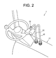
Fig. 2 is a partially enlarged perspective view of an operator's platform of the forklift truck ofFig. 1 ; -
Fig. 3 is a block diagram showing the electrical arrangement of the forklift truck ofFig. 1 ; -
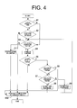
Fig. 4 is a flow chart illustrating the operation of the forklift truck ofFig. 1 ; -
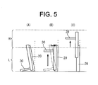
Fig. 5 is a schematic view showing the operation of the mast and the fork of the forklift truck ofFig. 1 ; - The
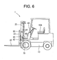
Fig. 6 is a schematic side view of a forklift truck according to a third preferred embodiment of the present invention; -
Fig. 7 is a block diagram showing the electrical arrangement of the forklift truck ofFig. 6 ; -
Fig. 8 is a schematic view showing the operation of the mast and the fork of the forklift truck ofFig. 6 when the fork is in its first lower lift region; -
Fig. 9 is a schematic view showing the operation of the mast and the fork of the forklift truck ofFig. 6 when the fork is in its second lower lift region; -
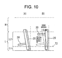
Fig. 10 is a schematic view showing the operation of the mast and the fork of a forklift truck according to a fourth preferred embodiment of the present invention when the fork is in its second lower lift region; and -
Fig. 11 is a flow chart illustrating the operation of a forklift truck according to a modification of the first preferred embodiment of the present invention. - The following will describe a forklift truck according to a first preferred embodiment of the present invention with reference to
Figs. 1 through 5 . Referring toFigs. 1 through 2 , thereference numeral 1 designates a forklift truck of the first preferred embodiment of the present invention. The following will describe the mechanical configuration and the electrical configuration of theforklift truck 1 separately. - The following will describe the mechanical configuration of the
forklift truck 1 with reference toFigs. 1 and2 . Theforklift truck 1 includes atruck body 10, amast 20 supported tiltably about a transverse axis of thetruck body 10 and afork 30 movable to be lifted and lowered through alift bracket 22 relative to themast 20. - The
truck body 10 includes atilt lever 40 and alift lever 50 which are operable by an operator seated on the operator's seat. Theforklift truck 1 includes a tilting mechanism (Fig. 3 ) in which themast 20 is tiltable about a transverse axis of thetruck body 10 by operating thetilt lever 40. Theforklift truck 1 includes a lifting mechanism (Fig. 3 ) in which thefork 30 is movable to be lifted and lowered through thelift bracket 22 relative to themast 20 by operating thelift lever 50. These tilting and liftingmechanisms - Referring to
Fig. 3 , the following will describe the electrical configuration of theforklift truck 1. Theforklift truck 1 includes theaforementioned tilting mechanism 60 and thelifting mechanism 64, atilting operation detector 62, alifting operation detector 66, anauxiliary switch 52, atilt angle detector 70, acontroller 74, a first liftedheight detector 80 and aload detector 90 which are electrically connected. - The
tilting mechanism 60 is used for tilting themast 20 about a transverse axis of thetruck body 10 and includes a tilt cylinder (not shown) connected to themast 20, a pump (not shown) supplying pressurized oil to the tilt cylinder, a motor (not shown) driving the pump and an electromagnetic valve (not shown) operable to adjust the amount of the pressurized oil to be supplied to the tilt cylinder. It is noted that the pump and the motor are shared by thetilting mechanism 60 and thelifting mechanism 64. The electromagnetic valve is electrically connected to thecontroller 74 and controlled by a signal from thecontroller 74. - Adjusting the amount of oil to be supplied to the tilt cylinder, the extension and retraction of the tilt cylinder and hence the tilting operation of the
mast 20 is controlled. Themast 20 is tilted according to the retraction of the tilt cylinder such that thefork 30 has a predetermined tilt angle. Thecontroller 74 controls the operation of the electromagnetic valve thereby to control thetilting mechanism 60. - The tilting
operation detector 62 is made of a lever switch and detects whether or not thetilt lever 40 is in operative position. The tiltingoperation detector 62 also detects the operation amount of thetilt lever 40. The tiltingoperation detector 62 is disposed adjacent to the bottom of thetilt lever 40 and electrically connected to thecontroller 74. Thecontroller 74 receives from the tiltingoperation detector 62 signals indicative of whether or not thetilt lever 40 is operated by the operator and the operation amount of thetilt lever 40. - The
lifting mechanism 64 which is used for lifting and lowering thefork 30 along themast 20 through thelift bracket 22. Specifically, thelifting mechanism 64 includes a lift cylinder (not shown) operable to lift and lower thefork 30 along themast 20, the aforementioned pump supplying pressurized oil to the lift cylinder, the aforementioned motor driving the pump and an electromagnetic valve (not shown) operable to adjust the amount of oil to be supplied to the tilt cylinder. The operation of the electromagnetic valve is controlled by a signal from thecontroller 74. Adjusting the amount of oil to be supplied to the lift cylinder, the extension and retraction of the lift cylinder and hence the lifting and lowering operation of thefork 30 is controlled. - The lifting
operation detector 66 is made of a lever switch and detects whether or not thelift lever 50 is placed in operative position. The liftingoperation detector 66 also detects the operation amount of thelift lever 50. The liftingoperation detector 66 is disposed adjacent to the bottom of thelift lever 50 and electrically connected to thecontroller 74. Thecontroller 74 receives from the lifting operation detector 66 a signal indicative of whether or not thelift lever 50 is operated by the operator of thelift lever 50 and the operation amount of thetilt lever 40. - The
auxiliary switch 52 is made, for example, of a switch which may be kept closed only while the switch is held pressed and used for activating an automatic leveling mechanism which will be described later. As shown inFig. 2 , theauxiliary switch 52 is disposed adjacent to a knob of thelift lever 50 that is formed at the end of thelift lever 50 and has an enlarged diameter. - The
auxiliary switch 52 is electrically connected to thecontroller 74. Thecontroller 74 determines whether or not theauxiliary switch 52 is closed or in operative position by the operator based on a signal (information) outputted from theauxiliary switch 52. - The
tilt angle detector 70 is made, for example, of a potentiometer and detects the tilt angle of themast 20 relative to the horizontal position of themast 20 to detect the tilt angle of thefork 30. Thetilt angle detector 70 is disposed in thetilting mechanism 60 on thetruck body 10 side of the tilt cylinder and electrically connected to thecontroller 74. Thecontroller 74 detects the tilt angle of thefork 30 based on a signal (information) from thetilt angle detector 70. Thecontroller 74 determines in real time whether thefork 30 is in a forward position, a horizontal position or a rearward position. - The first lifted
height detector 80 is made, for example, of a limit switch and detects the lifted height of thefork 30 relative to thetruck body 10. The first liftedheight detector 80 is disposed in themast 20 and electrically connected to thecontroller 74. Thecontroller 74 detects the lifted height of thefork 30 based on a signal (information) outputted from the first liftedheight detector 80.
Specifically, thecontroller 74 determines in real time whether the lifted height of thefork 30 is at or lower than the first threshold value, that is, in a lower lift region L, or higher than the first threshold value, that is, in a higher lift region H. The first threshold value is determined based on previously obtained experimental data in view of the operational reliability of theforklift truck 1. - The
load detector 90 is made, for example, of a sensor configured to detect any variation in hydraulic pressure of a hydraulic cylinder that forms a part of thelifting mechanism 64 and operable to detect whether or not a load is present on thefork 30. The hydraulic sensor detects the hydraulic pressure differential between the hydraulic cylinders before and after a load is placed on thefork 30 thereby to detect whether or not a load is present on thefork 30. Theload detector 90 is electrically connected to thecontroller 74 and thecontroller 74 determines whether or not a load is present on thefork 30 based on a signal (information) from theload detector 90. Theload detector 90 is not limited to the above hydraulic pressure sensor, but may be of any type of sensor as long as the presence of any load on thefork 30 is detected. A limit switch that is actuated by the presence of any load on thefork 30 may be mounted at any suitable position of thefork 30. - The
controller 74 controls the loading and traveling operation of theforklift truck 1. Specifically, thecontroller 74 is used for controlling the operation of thetilting mechanism 60 and thelifting mechanism 64 based on a signal generated by the tiltingoperation detector 62, the liftingoperation detector 66, theauxiliary switch 52, thetilt angle detector 70, the first liftedheight detector 80 and theload detector 90, as well as controlling the traveling operation of theforklift truck 1. Thecontroller 74 includes an electronic control unit (ECU) and a read only memory (ROM) storing therein programs which will be described in detail later. - The
controller 74 determines according to a first program stored therein whether or not thetilt lever 40 is in operative position and the operation amount of thetilt lever 40 based on a signal from the tiltingoperation detector 62 and generates signals for controlling the operation of thetilting mechanism 60 or the electromagnetic valve thereof. Thus, the tilting speed of thefork 30 forward or rearward is determined based on the amount of the tilt lever operated by the operator. When the operation amount of thetilt lever 40 is relatively small, thefork 30 is tilted at a low tilting speed. When the operation amount of thetilt lever 40 is relatively large, thefork 30 is tilted at a high tilting speed. - The
controller 74 determines according to the first program whether or not thelift lever 50 is placed in operative position and the operation amount of thelift lever 50 based on a signal from the liftingoperation detector 66 and generates signals for controlling the operation of thelifting mechanism 64 or the electromagnetic valve thereof. Thus, the lifting and lowering speed of thefork 30 are determined based on the amount of the operation of thelift lever 50 by the operator. When the operation amount of thelift lever 50 is relatively small, thefork 30 is lifted or lowered at a low speed. When the operation amount of thelift lever 50 is relatively large, thefork 30 is lifted or lowered at a high speed. - The
controller 74 also stores therein a second program according to which while performing the automatic leveling mechanism, thefork 30 is prevented from being tilted unless thefork 30 is located in a lower lift region and which will be described in detail in later part thereof. - The following will describe the above-mentioned second program of the
forklift truck 1 with reference toFigs. 4 and5 . At the first step S1, thecontroller 74 determines based on a signal (information) from theload detector 90 whether or not a load is present on thefork 30. If YES (or Y) at step S1, thecontroller 74 determines at step S2 based on the a signal (information) from the first liftedheight detector 80 whether or not thefork 30 is in the lower lift region L, as shown inFig. 5 at(A) . - If YES at step S2, or the
fork 30 is in the lower lift region L, thecontroller 74 determines at step S3 based on the signal from the liftingoperation detector 66 whether or not thelift lever 50 is placed in operative position. If YES at step S3, thecontroller 74 causes thefork 30 to be lifted at a speed that is determined by the operation amount of thelift lever 50 at step S4. Subsequently, thecontroller 74 determines at step S5 whether or not theauxiliary switch 52 is closed by the operator or in operative position. If YES at step S5, or thelift lever 50 is placed in operative position and theauxiliary switch 52 is in operative position, thecontroller 74 determines at step S6 based on the signal from thetilt angle detector 70 whether or not thefork 30 is in its horizontal position. - If NO at step S6, the
controller 74 determines at step S7 whether or not thefork 30 is in its forward position relative to thetilting mechanism 60. If YES at step S7, or thefork 30 is in its forward position, thecontroller 74 causes thefork 30 to be tilted rearward at a normal speed as shown inFig. 5 at(B) at step S8, and the sequence returns to step S3. If NO at step S7, or thefork 30 is in its rearward position, thefork 30 is tilted forward at a normal speed at step S9, and the sequence returns to step S3. The normal speed of tilting thefork 30 forward or rearward is previously set to an appropriate value in view of the desired efficiency in loading operation of thefork 30 and the safety in handling load on thefork 30. - While the
lift lever 50 is placed in operative position and theauxiliary switch 52 is in operative position, the sequence is repeated by thecontroller 74 until thecontroller 74 determines at step S6 that thefork 30 is in its horizontal position or until it is determined YES at step S6. If YES at step S6, thecontroller 74 causes thetilting mechanism 60 to be stopped at step S10 and the sequence goes to end. The sequence is restarted at step S1 and repeated. After thefork 30 is tilted to its horizontal position, thefork 30 continues to be lifted, as shown inFig. 5 at(C) , while thelift lever 50 is placed in operative position. - Thus, while performing the automatic leveling mechanism, the
fork 30 is prevented from being tilted to its horizontal position unless thefork 30 is in the lower lift region L. If NO at step S2, or no load is present on thefork 30, the step S2 proceeds to step 10. If NO at step S3, or thelift lever 50 is in inoperative position, thecontroller 74 causes thefork 30 to be stopped from lifting at step S11 by thecontroller 74 and the step S11 proceeds to step S10. - In the
forklift truck 1 according to the first preferred embodiment of the present invention, tilting of thefork 30 to its horizontal position while lifting thefork 30 is allowed only when thefork 30 is in the lower lift region L. If thefork 30 is in the higher lift region H, thefork 30 is prevented from being tiled to its horizontal position. Therefore, movement of thefork 30 to its horizontal position is performed with safety and stability. - The following will describe a second preferred embodiment of the present invention. The second preferred embodiment differs from the first preferred embodiment in that the first threshold value, or the threshold value between the lower lift region L and the higher lift region H is changeable according to a load weight applied to the
fork 30. - For this purpose, the
load detector 90 includes a mechanism for detecting the load weight applied to thefork 30, as well as the mechanism for detecting whether or not a load is present on thefork 30. Theload detector 90 is adapted to detect the variation of pressure of the hydraulic cylinder and includes a mechanism for determining the load weight applied to thefork 30. - According to the second preferred embodiment of the present invention, the first lifted
height detector 80 may be of a type that permits continuous detection of the lifted height of thefork 30 instead of the limit switch of the first embodiment, for example a so-called reel type wherein an encoder is mounted on a reel connected to the fork or the lift bracket through a wire and the lifted height is determined from the number of rotations of the reel. Thecontroller 74 determines in real time the lifted height of thefork 30 based on signals from the first liftedheight detector 80. - The
load detector 90 detects the load weight applied to thefork 30 and generates to the controller 74 a signal indicative of the detected load. Thecontroller 74 has stored therein a program for changing the first threshold value according to the extent of the load weight applied to thefork 30. Specifically, the first threshold value is changed to a higher value when the detected load weight is lower than a predetermined reference value or changed to a lower value when the detected load weight is greater than the predetermined reference value. The relation between the load weight and the first threshold value is set previously based on experimental data. - According to the
forklift truck 1 of the second preferred embodiment of the present invention, the first threshold value is changed according to the load weight on thefork 30. Therefore, when the load weight on thefork 30 is small, the range of the lifted height of thefork 30 in which thefork 30 is allowed to be lifted in its horizontal position may be widened while the safety and the stability of load on thefork 30 being maintained. - The following will describe a third preferred embodiment of the present invention with reference to
Figs. 4 and6 through 9 . According to the third preferred embodiment, the lifting speed of thefork 30 is changeable depending on the lifted height of thefork 30. As shown inFigs. 6 and7 , a second liftedheight detector 82 is provided in theforklift truck 1. - The second lifted
height detector 82 is made of a limit switch and detects the lifted height of thefork 30 relative to thetruck body 10. The second liftedheight detector 82 is disposed at a position that is adjacent to the bottom of themast 20 and lower than the first liftedheight detector 80. The second liftedheight detector 82 is electrically connected to thecontroller 74. - Thus, the
controller 74 determines based on the a signal (information) from the second liftedheight detector 82 whether the lifted height of thefork 30 is lower than the position corresponding to a second threshold value that is smaller than the first threshold value (or in the first lower lift region L1) or higher than the position (or in the second lower lift region L2 seeFig. 8 ). - The following will describe the operation of the
forklift truck 1 according to the third preferred embodiment of the present invention. The operation of theforklift truck 1 of the third preferred embodiment of the present invention is substantially the same as that of the first preferred embodiment of the present invention. Theforklift truck 1 of the third preferred embodiment differs from that of the first preferred embodiment in that thecontroller 74 determines at step S2 whether thefork 30 is in the first lower lift region L1 or in the second lower lift region L2 when thefork 30 is determined to be in the lower lift region L. If thecontroller 74 determines at step S2 that thefork 30 is in the first lower lift region L1, as shown inFig. 8 at(A) , thefork 30 is lifted at step S4 at a normal lifting speed and thefork 30 is tilted to its horizontal position at steps S8 and S9 at a normal tilting rearward speed, as shown inFig. 8 at(B) . - On the other hand, if the
controller 74 determines at step S2 that thefork 30 is in the second lower lift region L2, as shown inFig. 9 at(A) , thefork 30 is lifted at step S4 at a low lifting speed and thefork 30 is tilted to its horizontal position at steps S8 and S9 at a normal tilting rearward speed or normal tilting frontward speed, as shown inFig. 9 at(B) . The above low lifting speed, which has been set previously based on experimental data in view of the desired efficiency in loading operation of thefork 30, as well as of the safety in handling load on thefork 30, will not affect the working efficiency of theforklift truck 1. - According to the
forklift truck 1 of the third preferred embodiment, if thefork 30 is in the first lower lift region L1, thefork 30 is lifted at a normal lifting speed, while if thefork 30 is in the second lower lift region L2, thefork 30 is lifted at a low lifting speed. Thus, the lifting speed of thefork 30 is changed depending on the lifted height of thefork 30. Therefore, the tilting of thefork 30 to its horizontal position is performed at a relatively low lifted height of thefork 30, so that thefork 30 with a load may be lifted stably. - The following will describe the
forklift truck 1 according to a fourth preferred embodiment of the present invention with reference toFig. 10 . Theforklift truck 1 of the fourth preferred embodiment differs from that of the third preferred embodiment in that the tilting speed of thefork 30 to its horizontal position is changeable according to the lifted height of thefork 30. - Unlike the
forklift truck 1 of the third preferred embodiment wherein thefork 30 located in the second lower lift region L2 is lifted at a low lifting speed that is lower than normal operation, thefork 30 in the same second lower lift region L2 is lifted at a normal lifting speed and the tilting of thefork 30 to its horizontal position is performed at a fast tilting speed that is faster than the normal, as shown in the drawings (A) and (B) ofFig. 10 . According to theforklift truck 1 of the fourth preferred embodiment of the present invention, the lifting speed of thefork 30 in the second lower lift region L2 is normal. The tilting speed of thefork 30 to its horizontal position is faster than normal as shown in the drawings (A) and (B) ofFig. 10 . Thus, thefork 30 is lifted at the normal lifting speed but tilted at a fast tilting speed so that thefork 30 located initially in the second lower lift region L2 may be tilted to its horizontal position before thefork 30 is lifted to a position corresponding to the first threshold value. Thus, the operation of the tilting of thefork 30 to its horizontal position is performed in a region of relatively low lifted height of thefork 30, so that thefork 30 with a load may be lifted stably. The tilting speed which is faster than the normal speed but lower than the speed when thelift lever 50 operated to its maximum position is previously set to an appropriate value based on experimental data in view of the safety in handling load on thefork 30. - Although the first through fourth preferred embodiments according to the present invention have been described, the present invention is not limited to such embodiments.
- According to the first preferred embodiment, the
fork 30 being lifted in the higher lift region H is prevented from tilting toward its horizontal position. Thefork 30 being lowered in the higher lift region H may also be prevented form tilting toward its horizontal position. In this case, the determination of whether or not thefork 30 located in the higher lift region H is performed at step S2 and a step for determination of whether or not the lifted height of thefork 30 is in the lower lift region L is added after the determination at step S7. If YES at step S2, the procedure proceeds to step S8 or S9. - According to the
forklift truck 1 of the first preferred embodiment of the present invention, thefork 30 continues to be tilted toward its horizontal position after thefork 30 is lifted to the higher lift region H. However, the present invention is not limited to this structure. Theforklift truck 1 of the first preferred embodiment may be modified and controlled by thecontroller 74 in such a way that the tilting of thefork 30 toward its horizontal position is stopped or the operation of thetilting mechanism 60 to lift thefork 30 is stopped when thefork 30 reaches the higher lift region H. - The following will describe the operation of the above modified
forklift truck 1 with reference toFig. 11 . At step S101, thecontroller 74 determines whether or not a load is present on thefork 30. If YES at step S101, thecontroller 74 determines at step S102 whether or not the lifted height of thefork 30 is in the lower lift region L. - If YES at step S102, the
controller 74 determines at step S103 whether or not thelift lever 50 is placed in operative position. If YES at step S103, thecontroller 74 causes at step S104 thefork 30 to be lifted. Then, thecontroller 74 determines at step S105 whether or not theauxiliary switch 52 is in operative position. If YES at step S105, thecontroller 74 determines at step S106 whether or not a load is present on thefork 30. - If YES at step S106, the
controller 74 determines at step S107 whether or not the lifted height of thefork 30 is in the lower lift region L. If YES at step S107, thecontroller 74 determines at step S108 whether or not thefork 30 is in its horizontal position. - If NO at step S108, the
controller 74 determines at step S109 whether or not thefork 30 is in its frontward position. If YES at step S109, thefork 30 is tilted rearward at S110 and the sequence returns to step S103. On the other hand, if NO at step S109, thefork 30 is tilted frontward at step S111 and the sequence returns to step S103. - Thereafter, continuing to operate the
lift lever 50 and theauxiliary switch 52 by the operator, steps S103 through S111 are repeated until NO determination is made at step S107 or YES determination is made atstep 108. - NO at step S107 means that the lifted height of the
fork 30 is no more in the lower lift region L, or thefork 30 has reached the higher lift region H that is above the first threshold value level. Then atstep 112, thecontroller 74 causes thefork 30 to stop its tilting frontward or rearward and the sequence goes to end. - YES at step S108 means that the
fork 30 is in its horizontal position. Then at step S112, thecontroller 74 causes thefork 30 to stop its tilting forward or rearward and the sequence goes to end. The sequence is returned to step S101 and the step thereof is performed repeatedly. - If NO at step S102, the step S101 proceeds to S112. If NO at step S103, the
controller 74 causes thefork 30 to stop the lifting at step S113 and the sequence goes to step S112. If NO at step S105, the sequence goes to step S112. If NO at step S106, the sequence goes to step S108. - According to the preferred embodiments, the
auxiliary switch 52 is disposed adjacent to the knob of thelift lever 50. Theauxiliary switch 52 may be disposed at any position near the operator's seat that allows the operator to operate theauxiliary switch 52 simultaneously with manipulation of the loading lever. - A forklift truck includes a truck body, a fork, a mast, tilting and lifting mechanisms, tilt and lift levers, tilting and lifting operation detectors, a lifted height detector, a load detector, an auxiliary switch, a tilt angle detector and a controller. The controller controls the lifting and tilting mechanisms based on signals from the tilting and lifting operation detectors and the auxiliary switch. The controller controls the lifting and tilting mechanisms to cause the fork to be lifted and tilted to horizontal position of the fork if a load is present on the fork, the fork is in a lower lift region where the lifted height of the fork is at or lower than a first threshold value, the lift lever is placed in operative position to lift the fork, the auxiliary switch is in operative position and the fork is not in the horizontal position of the fork.
Claims (7)
- A forklift truck (1) including a truck body (10), a fork (30) and a mast (20) movable to be lifted, lowered and tilted together with the fork (30), the forklift truck (1) comprising:a tilting mechanism (60) adapted to tilt the mast (20) relative to the truck body (10);a tilt lever (40) adapted to operate the tilting mechanism (60);a tilting operation detector (62) adapted to detect whether or not the tilt lever (40) is in operative position;a lifting mechanism (64) adapted to lift and lower the fork (30) along the mast (20);a lift lever (50) adapted to operate the lifting mechanism (64); anda lifting operation detector (66) adapted to detect whether or not the lift lever (50) is in operative position,characterized in that the forklift truck (1) further includes a lifted height detector (80, 82) detecting the lifted height of the fork (30), a load detector (90) adapted to detect whether or not a load is present on the fork (30), an auxiliary switch (52) disposed at a position which allows the operator to operate the auxiliary switch (52), a tilt angle detector (70) adapted to detect a tilt angle of the mast (20) and a controller (74) adapted to control the lifting mechanism (64) and the tilting mechanism (60) based on signals from the tilting operation detector (62), the lifting operation detector (66) and the auxiliary switch (52), wherein the controller (74) controls the lifting mechanism (64) and the tilting mechanism (60) to cause the fork (30) to be lifted and tilted to horizontal position of the fork (30) if the load detector (90) detects that a load is present on the fork (30), the fork (30) is in a lower lift region (L) where the lifted height of the fork (30) detected by the lifted height detector (80, 82) is at or lower than a first threshold value, the lifting operation detector (66) detects that the lift lever (50) is placed in operative position to lift the fork (30), the auxiliary switch (52) is in operative position and the controller (74) detects that the fork (30) is not in the horizontal position of the fork (30) based on a signal from the tilt angle detector (70).
- The forklift truck (1) according to claim 1, characterized in that the controller (74) controls only the lifting mechanism (64) to cause the fork (30) to be lowered if the load detector (90) detects that a load is present on the fork (30) and the fork is in a higher lift region (H) where the lifted height of the fork (30) detected by the lifted height detector (80, 82) is higher than the first threshold value, the lifting operation detector (66) detects that the lift lever (50) is placed in operative position to lower the fork (30) and the auxiliary switch (52) is in operative position, and the controller (74) controls the lifting mechanism (64) and the tilting mechanism (60) to cause the fork (30) to be lowered and tilted to horizontal position of the fork (30) if the fork (30) is in the lower lift region (L), the lifting operation detector (66) detects that the lift lever (50) is placed in operative position to lower the fork (30) and the auxiliary switch (52) is in operative position.
- The forklift truck (1) according to claim 1, characterized in that while the controller (74) controls the lifting mechanism (64) and the tilting mechanism (60) to cause the fork (30) in the lower lift region (L) to be lifted and tilted to the horizontal position of the fork (30), the tilting of the fork (30) to the horizontal position of the fork (30) is stopped if the fork (30) reaches the higher lift region (H).
- The forklift truck (1) according to any one of claims 1 through 3, characterized in that the load detector (90) is further adapted to detect a load weight applied to the fork (30), the lifted height detector (80, 82) permits continuous detection of the lifted height of the fork (30) and the controller (74) changes the first threshold value according to the load weight.
- The forklift truck (1) according to any one of claims claim 1 through 4, characterized in that a tilting speed of the mast (20) is changeable by the tilting mechanism (60) to a normal tilting speed or a fast tilting speed which is faster than the normal tilting speed, a lifting speed of the fork (30) is changeable by the lifting mechanism (64) to a normal lifting speed or a low lifting speed which is lower than the normal lifting speed,
the controller (74) controls the lifting mechanism (64) and the tilting mechanism (60) to cause the fork (30) to be lifted at the normal lifting speed and tilted to horizontal position of the fork (30) at the normal tilting speed if the lifting operation detector (62) detects that the lift lever (50) is placed in operative position to lift the fork (30), the auxiliary switch (52) is in operative position, the load detector (90) detects that a load is present on the fork (30), the fork (30) is in the lower lift region (L), the lifted height of the fork (30) detected by the lifted height detector (80, 82) is at or lower than a second threshold value which is lower than the first threshold value and the controller (74) detects that the fork (30) is not in the horizontal position of the fork (30) based on a signal from the tilt angle detector (70), and the controller (74) controls the lifting mechanism (64) and the tilting mechanism (60) to cause the fork (30) to be lifted at the low lifting speed and tilted to horizontal position of the fork (30) at the normal tilting speed or lifted at the normal lifting speed and tilted to the horizontal position of the fork (30) at the high tilting speed if the lifting operation detector (66) detects that the lift lever (50) is placed in operative position to lift the fork (30), the auxiliary switch (52) is in operative position, the load detector (90) detects that a load is present on the fork (30), the fork (30) is in the lower lift region (L), the lifted height of the fork (30) detected by the lifted height detector (80, 82) is higher than the second threshold value and the controller (74) detects that the fork (30) is not in the horizontal position of the fork (30) based on a signal from the tilt angle detector (70). - A method for controlling a forklift truck (1), the forklift truck (1) including:a truck body (10);a fork (30);a mast (20) movable to be lifted, lowered and tilted together with the fork (30);a tilting mechanism (60) adapted to tilt the mast (20) relative to the truck body (10);a tilt lever (40) adapted to operate the tilting mechanism (60);a tilting operation detector (62) adapted to detect whether or not the tilt lever (40) is placed in operative position;a lifting mechanism (64) adapted to lift and lower the fork (30) along the mast (20);a lift lever (50) adapted to operate the lifting mechanism (64);a lifting operation detector (66) adapted to detect whether or not the lift lever (50) is placed in operative position;a lifted height detector (80, 82) adapted to detect the lifted height of the fork (30);a load detector (90) adapted to detect whether or not a load is present on the fork (30);an auxiliary switch (52) disposed at a position which allows the operator to operate the auxiliary switch (52);a tilt angle detector (70) adapted to detect a tilt angle of the mast (20);
anda controller (74) adapted to control the lifting mechanism (64) and the tilting mechanism (60) based on signals from the tilting operation detector (62), the lifting operation detector (66) and the auxiliary switch (52),the method characterized by the steps of:controlling the lifting mechanism (64) to cause the fork (30) to be lowered if the load detector (90) detects that a load is present on the fork (30), the fork (30) is in a higher lift region (H) where the lifted height of the fork (30) detected by the lifted height detector (80, 82) is higher than a first threshold value, the lifting operation detector (66) detects that the lift lever (50) is placed in operative position to lower the fork (30) and the auxiliary switch (52) is in operative position or controlling the lifting mechanism (64) and tilting mechanism (64) to cause the fork (30) to be lifted and tilted to the horizontal position of the fork (30) if the load detector (90) detects that a load is present on the fork (30), the fork (30) is in a lower lift region (L) where the lifted height of the fork (30) detected by the lifted height detector (80, 82) is at or lower the first threshold value, the lifting operation detector (66) detects that the lift lever (50) is placed in operative position to lift the fork (30) and the auxiliary switch (52) is in operative position; andcontrolling the tilting mechanism (60) to cause the fork (30) to be tilted to horizontal position of the fork (30) if the fork (30) reaches the lower lift region (L) from the higher lift region (H) or controlling the tilting mechanism (60) to cause the fork (30) to be stopped from tilting if the fork (30) is reaches the higher lift region (H) from the lower lift region (L). - The method according to claim 6, characterized in that the load detector (90) is further adapted to detect a load weight applied to the fork (30), the lifted height detector (80, 82) permits continuous detection of the lifted height of the fork (30) and the controller (74) changes the first threshold value according to the load weight.
Applications Claiming Priority (1)
| Application Number | Priority Date | Filing Date | Title |
|---|---|---|---|
| JP2011214449A JP5621742B2 (en) | 2011-09-29 | 2011-09-29 | forklift |
Publications (2)
| Publication Number | Publication Date |
|---|---|
| EP2574589A1 true EP2574589A1 (en) | 2013-04-03 |
| EP2574589B1 EP2574589B1 (en) | 2015-07-22 |
Family
ID=46980798
Family Applications (1)
| Application Number | Title | Priority Date | Filing Date |
|---|---|---|---|
| EP12185635.5A Active EP2574589B1 (en) | 2011-09-29 | 2012-09-24 | Forklift truck with controlled mast tilt |
Country Status (3)
| Country | Link |
|---|---|
| US (1) | US8930093B2 (en) |
| EP (1) | EP2574589B1 (en) |
| JP (1) | JP5621742B2 (en) |
Cited By (7)
| Publication number | Priority date | Publication date | Assignee | Title |
|---|---|---|---|---|
| WO2015121685A1 (en) * | 2014-02-14 | 2015-08-20 | B J E Designs Limited | A load handling apparatus for a forklift |
| EP2998266A1 (en) * | 2014-09-22 | 2016-03-23 | Kabushiki Kaisha Toyota Jidoshokki | Apparatus for controlling load handling device |
| EP3020678A1 (en) * | 2014-10-08 | 2016-05-18 | Kabushiki Kaisha Toyota Jidoshokki | Apparatus for controlling load handling device |
| US9932213B2 (en) | 2014-09-15 | 2018-04-03 | Crown Equipment Corporation | Lift truck with optical load sensing structure |
| CN108298481A (en) * | 2018-03-07 | 2018-07-20 | 安徽合力股份有限公司 | A kind of control system and method preventing fork of forklift truck high position maloperation |
| US10430073B2 (en) | 2015-07-17 | 2019-10-01 | Crown Equipment Corporation | Processing device having a graphical user interface for industrial vehicle |
| CN110562884A (en) * | 2019-08-08 | 2019-12-13 | 安徽合力股份有限公司 | Forklift gantry forward-inclination angle control system and control method |
Families Citing this family (12)
| Publication number | Priority date | Publication date | Assignee | Title |
|---|---|---|---|---|
| GB2510082B (en) * | 2011-10-21 | 2017-04-19 | Mobot Ind Ltd | A lifting apparatus |
| US20150318765A1 (en) | 2014-04-30 | 2015-11-05 | Rossie Owen Terry | Electrical motors and methods thereof having reduced electromagnetic emissions |
| JP6559504B2 (en) * | 2015-08-27 | 2019-08-14 | 三菱ロジスネクスト株式会社 | forklift |
| JP6551284B2 (en) * | 2016-04-04 | 2019-07-31 | 株式会社豊田自動織機 | Forklift control method |
| EP3545398B1 (en) | 2016-11-22 | 2023-01-04 | Crown Equipment Corporation | User interface device for industrial vehicle |
| CN106744515A (en) * | 2016-12-16 | 2017-05-31 | 宁波力达物流设备有限公司 | The automatic leveling device for fork and leveling method of electri forklift |
| IT201900005060A1 (en) * | 2019-04-04 | 2020-10-04 | Dana Motion Sys Italia Srl | Method and system for controlling the ground grip of a wheel loader. |
| JP2022086361A (en) * | 2020-11-30 | 2022-06-09 | 株式会社日立製作所 | Vehicle control and method |
| CN112811361B (en) * | 2021-02-04 | 2022-04-26 | 合肥工业大学 | A safety control system for forklift manual valve operation fork |
| JP7824719B2 (en) * | 2022-03-30 | 2026-03-05 | 住友ナコ フォ-クリフト株式会社 | Cargo handling vehicle, loading control method, and loading control program |
| JP7607618B2 (en) * | 2022-08-05 | 2024-12-27 | 三菱ロジスネクスト株式会社 | Bias estimation device, forklift, bias estimation method and program |
| JP7615114B2 (en) * | 2022-12-22 | 2025-01-16 | 三菱ロジスネクスト株式会社 | Display device, unloading assistance system, industrial vehicle, control method and program |
Citations (4)
| Publication number | Priority date | Publication date | Assignee | Title |
|---|---|---|---|---|
| JPH09295800A (en) | 1996-05-01 | 1997-11-18 | Toyota Autom Loom Works Ltd | Tilt control device for forklift |
| EP0866027A2 (en) * | 1997-03-21 | 1998-09-23 | Kabushiki Kaisha Toyoda Jidoshokki Seisakusho | Hydraulic control apparatus for industrial vehicles |
| US6092976A (en) * | 1997-12-11 | 2000-07-25 | Kabushiki Kaisha Toyoda Jidoshokki Seisakusho | Delayed-action empty-seat safety interlock for forklift controls |
| US7320385B2 (en) * | 2001-02-16 | 2008-01-22 | Kabushiki Kaisha Toyota Jidoshokki | Camera lifting apparatus and cargo handling operation aiding apparatus in industrial vehicle and industrial vehicle |
Family Cites Families (12)
| Publication number | Priority date | Publication date | Assignee | Title |
|---|---|---|---|---|
| JP3201076B2 (en) * | 1993-07-07 | 2001-08-20 | 株式会社豊田自動織機製作所 | Loading control device for battery-powered industrial vehicles |
| JPH07242398A (en) * | 1994-03-03 | 1995-09-19 | Toyota Autom Loom Works Ltd | Stabilization degree informing device for cargo handling vehicle |
| JPH0925099A (en) | 1995-07-07 | 1997-01-28 | Nippon Yusoki Co Ltd | Automatic tilt angle adjusting device |
| JPH10167691A (en) * | 1996-12-04 | 1998-06-23 | Nippon Yusoki Co Ltd | Operating device of fork lift |
| JP2000109299A (en) * | 1998-10-02 | 2000-04-18 | Nippon Yusoki Co Ltd | Cargo handling device for counterbalance type forklift |
| JP3301416B2 (en) * | 1999-08-23 | 2002-07-15 | 株式会社豊田自動織機 | Mast tilting speed control device for industrial vehicles |
| JP2001316096A (en) * | 2000-02-28 | 2001-11-13 | Toyota Industries Corp | Hydraulic device for industrial vehicle |
| US20030024132A1 (en) * | 2000-06-14 | 2003-02-06 | Nippon Yusoki Co., Ltd. | Cargo handling vehicle |
| JP2003089500A (en) * | 2001-07-12 | 2003-03-25 | Toyota Industries Corp | Loading lever and industrial vehicle |
| GB2413547B (en) * | 2004-04-07 | 2007-06-06 | Linde Ag | Industrial truck having increased static/quasi-static and dynamic tipping stability |
| JP4807028B2 (en) * | 2005-09-30 | 2011-11-02 | 株式会社豊田自動織機 | Forklift travel control device |
| JP5067261B2 (en) * | 2008-05-27 | 2012-11-07 | 株式会社豊田自動織機 | Operating device |
-
2011
- 2011-09-29 JP JP2011214449A patent/JP5621742B2/en active Active
-
2012
- 2012-09-24 EP EP12185635.5A patent/EP2574589B1/en active Active
- 2012-09-25 US US13/626,210 patent/US8930093B2/en active Active
Patent Citations (4)
| Publication number | Priority date | Publication date | Assignee | Title |
|---|---|---|---|---|
| JPH09295800A (en) | 1996-05-01 | 1997-11-18 | Toyota Autom Loom Works Ltd | Tilt control device for forklift |
| EP0866027A2 (en) * | 1997-03-21 | 1998-09-23 | Kabushiki Kaisha Toyoda Jidoshokki Seisakusho | Hydraulic control apparatus for industrial vehicles |
| US6092976A (en) * | 1997-12-11 | 2000-07-25 | Kabushiki Kaisha Toyoda Jidoshokki Seisakusho | Delayed-action empty-seat safety interlock for forklift controls |
| US7320385B2 (en) * | 2001-02-16 | 2008-01-22 | Kabushiki Kaisha Toyota Jidoshokki | Camera lifting apparatus and cargo handling operation aiding apparatus in industrial vehicle and industrial vehicle |
Cited By (10)
| Publication number | Priority date | Publication date | Assignee | Title |
|---|---|---|---|---|
| WO2015121685A1 (en) * | 2014-02-14 | 2015-08-20 | B J E Designs Limited | A load handling apparatus for a forklift |
| US9932213B2 (en) | 2014-09-15 | 2018-04-03 | Crown Equipment Corporation | Lift truck with optical load sensing structure |
| EP2998266A1 (en) * | 2014-09-22 | 2016-03-23 | Kabushiki Kaisha Toyota Jidoshokki | Apparatus for controlling load handling device |
| US9731950B2 (en) | 2014-09-22 | 2017-08-15 | Kabushiki Kaisha Toyota Jidoshokki | Apparatus for controlling load handling device |
| EP3020678A1 (en) * | 2014-10-08 | 2016-05-18 | Kabushiki Kaisha Toyota Jidoshokki | Apparatus for controlling load handling device |
| US9828225B2 (en) | 2014-10-08 | 2017-11-28 | Kabushiki Kaisha Toyota Jidoshokki | Apparatus for controlling load handling device |
| US10430073B2 (en) | 2015-07-17 | 2019-10-01 | Crown Equipment Corporation | Processing device having a graphical user interface for industrial vehicle |
| CN108298481A (en) * | 2018-03-07 | 2018-07-20 | 安徽合力股份有限公司 | A kind of control system and method preventing fork of forklift truck high position maloperation |
| CN108298481B (en) * | 2018-03-07 | 2024-01-05 | 安徽合力股份有限公司 | Control system and method for preventing high-order misoperation of forklift fork |
| CN110562884A (en) * | 2019-08-08 | 2019-12-13 | 安徽合力股份有限公司 | Forklift gantry forward-inclination angle control system and control method |
Also Published As
| Publication number | Publication date |
|---|---|
| EP2574589B1 (en) | 2015-07-22 |
| JP2013071839A (en) | 2013-04-22 |
| US8930093B2 (en) | 2015-01-06 |
| JP5621742B2 (en) | 2014-11-12 |
| US20130085646A1 (en) | 2013-04-04 |
Similar Documents
| Publication | Publication Date | Title |
|---|---|---|
| EP2574589B1 (en) | Forklift truck with controlled mast tilt | |
| EP3020678B1 (en) | Apparatus for controlling load handling device | |
| JP5401773B2 (en) | Fork lift control device for forklift | |
| EP2998266A1 (en) | Apparatus for controlling load handling device | |
| EP2574590B1 (en) | Forklift truck with controlled mast tilt | |
| JP5123771B2 (en) | Forklift tilt control device and forklift equipped with the device | |
| US20240239637A1 (en) | Forklift and method for controlling forklift | |
| JPH07242398A (en) | Stabilization degree informing device for cargo handling vehicle | |
| EP2123596B1 (en) | Arrangement and method for controlling the position of the forks of an industrial truck | |
| KR20150114842A (en) | Forklift fork kept horizontality system and that control method | |
| JP6559504B2 (en) | forklift | |
| JP4806984B2 (en) | forklift | |
| KR20210156582A (en) | Cargo drop prevention system for industrial vehicles and control method therefor | |
| KR102367107B1 (en) | Control method of forklift | |
| JP6551284B2 (en) | Forklift control method | |
| KR20180009875A (en) | Apparatus and method for controlling mast angle of forklift truck | |
| JP5453857B2 (en) | Cargo handling vehicle | |
| JP6927656B1 (en) | Forklift with ram | |
| KR102377763B1 (en) | safety apparatus for dump truck | |
| JP6988694B2 (en) | Side forklift | |
| US20260015217A1 (en) | Automatic fork adjustment system and method | |
| JP4890842B2 (en) | Safety equipment for aerial work platforms | |
| JP2026015942A (en) | Loading platform lifting device and vehicle | |
| JP2000191296A (en) | Tilt control device of fork lift truck | |
| JP5294276B2 (en) | forklift |
Legal Events
| Date | Code | Title | Description |
|---|---|---|---|
| PUAI | Public reference made under article 153(3) epc to a published international application that has entered the european phase |
Free format text: ORIGINAL CODE: 0009012 |
|
| 17P | Request for examination filed |
Effective date: 20120924 |
|
| AK | Designated contracting states |
Kind code of ref document: A1 Designated state(s): AL AT BE BG CH CY CZ DE DK EE ES FI FR GB GR HR HU IE IS IT LI LT LU LV MC MK MT NL NO PL PT RO RS SE SI SK SM TR |
|
| AX | Request for extension of the european patent |
Extension state: BA ME |
|
| GRAP | Despatch of communication of intention to grant a patent |
Free format text: ORIGINAL CODE: EPIDOSNIGR1 |
|
| INTG | Intention to grant announced |
Effective date: 20150202 |
|
| GRAS | Grant fee paid |
Free format text: ORIGINAL CODE: EPIDOSNIGR3 |
|
| GRAA | (expected) grant |
Free format text: ORIGINAL CODE: 0009210 |
|
| AK | Designated contracting states |
Kind code of ref document: B1 Designated state(s): AL AT BE BG CH CY CZ DE DK EE ES FI FR GB GR HR HU IE IS IT LI LT LU LV MC MK MT NL NO PL PT RO RS SE SI SK SM TR |
|
| REG | Reference to a national code |
Ref country code: GB Ref legal event code: FG4D |
|
| REG | Reference to a national code |
Ref country code: CH Ref legal event code: EP |
|
| REG | Reference to a national code |
Ref country code: IE Ref legal event code: FG4D |
|
| REG | Reference to a national code |
Ref country code: AT Ref legal event code: REF Ref document number: 737768 Country of ref document: AT Kind code of ref document: T Effective date: 20150815 |
|
| REG | Reference to a national code |
Ref country code: DE Ref legal event code: R096 Ref document number: 602012008893 Country of ref document: DE |
|
| REG | Reference to a national code |
Ref country code: AT Ref legal event code: MK05 Ref document number: 737768 Country of ref document: AT Kind code of ref document: T Effective date: 20150722 |
|
| REG | Reference to a national code |
Ref country code: LT Ref legal event code: MG4D |
|
| REG | Reference to a national code |
Ref country code: NL Ref legal event code: MP Effective date: 20150722 |
|
| PG25 | Lapsed in a contracting state [announced via postgrant information from national office to epo] |
Ref country code: LV Free format text: LAPSE BECAUSE OF FAILURE TO SUBMIT A TRANSLATION OF THE DESCRIPTION OR TO PAY THE FEE WITHIN THE PRESCRIBED TIME-LIMIT Effective date: 20150722 Ref country code: NO Free format text: LAPSE BECAUSE OF FAILURE TO SUBMIT A TRANSLATION OF THE DESCRIPTION OR TO PAY THE FEE WITHIN THE PRESCRIBED TIME-LIMIT Effective date: 20151022 Ref country code: GR Free format text: LAPSE BECAUSE OF FAILURE TO SUBMIT A TRANSLATION OF THE DESCRIPTION OR TO PAY THE FEE WITHIN THE PRESCRIBED TIME-LIMIT Effective date: 20151023 Ref country code: FI Free format text: LAPSE BECAUSE OF FAILURE TO SUBMIT A TRANSLATION OF THE DESCRIPTION OR TO PAY THE FEE WITHIN THE PRESCRIBED TIME-LIMIT Effective date: 20150722 Ref country code: LT Free format text: LAPSE BECAUSE OF FAILURE TO SUBMIT A TRANSLATION OF THE DESCRIPTION OR TO PAY THE FEE WITHIN THE PRESCRIBED TIME-LIMIT Effective date: 20150722 |
|
| PG25 | Lapsed in a contracting state [announced via postgrant information from national office to epo] |
Ref country code: AT Free format text: LAPSE BECAUSE OF FAILURE TO SUBMIT A TRANSLATION OF THE DESCRIPTION OR TO PAY THE FEE WITHIN THE PRESCRIBED TIME-LIMIT Effective date: 20150722 Ref country code: RS Free format text: LAPSE BECAUSE OF FAILURE TO SUBMIT A TRANSLATION OF THE DESCRIPTION OR TO PAY THE FEE WITHIN THE PRESCRIBED TIME-LIMIT Effective date: 20150722 Ref country code: IS Free format text: LAPSE BECAUSE OF FAILURE TO SUBMIT A TRANSLATION OF THE DESCRIPTION OR TO PAY THE FEE WITHIN THE PRESCRIBED TIME-LIMIT Effective date: 20151122 Ref country code: HR Free format text: LAPSE BECAUSE OF FAILURE TO SUBMIT A TRANSLATION OF THE DESCRIPTION OR TO PAY THE FEE WITHIN THE PRESCRIBED TIME-LIMIT Effective date: 20150722 Ref country code: SE Free format text: LAPSE BECAUSE OF FAILURE TO SUBMIT A TRANSLATION OF THE DESCRIPTION OR TO PAY THE FEE WITHIN THE PRESCRIBED TIME-LIMIT Effective date: 20150722 Ref country code: ES Free format text: LAPSE BECAUSE OF FAILURE TO SUBMIT A TRANSLATION OF THE DESCRIPTION OR TO PAY THE FEE WITHIN THE PRESCRIBED TIME-LIMIT Effective date: 20150722 Ref country code: PT Free format text: LAPSE BECAUSE OF FAILURE TO SUBMIT A TRANSLATION OF THE DESCRIPTION OR TO PAY THE FEE WITHIN THE PRESCRIBED TIME-LIMIT Effective date: 20151123 Ref country code: PL Free format text: LAPSE BECAUSE OF FAILURE TO SUBMIT A TRANSLATION OF THE DESCRIPTION OR TO PAY THE FEE WITHIN THE PRESCRIBED TIME-LIMIT Effective date: 20150722 |
|
| REG | Reference to a national code |
Ref country code: DE Ref legal event code: R097 Ref document number: 602012008893 Country of ref document: DE |
|
| PG25 | Lapsed in a contracting state [announced via postgrant information from national office to epo] |
Ref country code: MC Free format text: LAPSE BECAUSE OF FAILURE TO SUBMIT A TRANSLATION OF THE DESCRIPTION OR TO PAY THE FEE WITHIN THE PRESCRIBED TIME-LIMIT Effective date: 20150722 Ref country code: CZ Free format text: LAPSE BECAUSE OF FAILURE TO SUBMIT A TRANSLATION OF THE DESCRIPTION OR TO PAY THE FEE WITHIN THE PRESCRIBED TIME-LIMIT Effective date: 20150722 Ref country code: LU Free format text: LAPSE BECAUSE OF FAILURE TO SUBMIT A TRANSLATION OF THE DESCRIPTION OR TO PAY THE FEE WITHIN THE PRESCRIBED TIME-LIMIT Effective date: 20150924 Ref country code: SK Free format text: LAPSE BECAUSE OF FAILURE TO SUBMIT A TRANSLATION OF THE DESCRIPTION OR TO PAY THE FEE WITHIN THE PRESCRIBED TIME-LIMIT Effective date: 20150722 Ref country code: EE Free format text: LAPSE BECAUSE OF FAILURE TO SUBMIT A TRANSLATION OF THE DESCRIPTION OR TO PAY THE FEE WITHIN THE PRESCRIBED TIME-LIMIT Effective date: 20150722 Ref country code: DK Free format text: LAPSE BECAUSE OF FAILURE TO SUBMIT A TRANSLATION OF THE DESCRIPTION OR TO PAY THE FEE WITHIN THE PRESCRIBED TIME-LIMIT Effective date: 20150722 |
|
| REG | Reference to a national code |
Ref country code: CH Ref legal event code: PL |
|
| PLBE | No opposition filed within time limit |
Free format text: ORIGINAL CODE: 0009261 |
|
| STAA | Information on the status of an ep patent application or granted ep patent |
Free format text: STATUS: NO OPPOSITION FILED WITHIN TIME LIMIT |
|
| PG25 | Lapsed in a contracting state [announced via postgrant information from national office to epo] |
Ref country code: RO Free format text: LAPSE BECAUSE OF FAILURE TO SUBMIT A TRANSLATION OF THE DESCRIPTION OR TO PAY THE FEE WITHIN THE PRESCRIBED TIME-LIMIT Effective date: 20150722 |
|
| 26N | No opposition filed |
Effective date: 20160425 |
|
| REG | Reference to a national code |
Ref country code: IE Ref legal event code: MM4A |
|
| PG25 | Lapsed in a contracting state [announced via postgrant information from national office to epo] |
Ref country code: CH Free format text: LAPSE BECAUSE OF NON-PAYMENT OF DUE FEES Effective date: 20150930 Ref country code: IE Free format text: LAPSE BECAUSE OF NON-PAYMENT OF DUE FEES Effective date: 20150924 Ref country code: LI Free format text: LAPSE BECAUSE OF NON-PAYMENT OF DUE FEES Effective date: 20150930 |
|
| REG | Reference to a national code |
Ref country code: FR Ref legal event code: PLFP Year of fee payment: 5 |
|
| PG25 | Lapsed in a contracting state [announced via postgrant information from national office to epo] |
Ref country code: SI Free format text: LAPSE BECAUSE OF FAILURE TO SUBMIT A TRANSLATION OF THE DESCRIPTION OR TO PAY THE FEE WITHIN THE PRESCRIBED TIME-LIMIT Effective date: 20150722 |
|
| PG25 | Lapsed in a contracting state [announced via postgrant information from national office to epo] |
Ref country code: BE Free format text: LAPSE BECAUSE OF FAILURE TO SUBMIT A TRANSLATION OF THE DESCRIPTION OR TO PAY THE FEE WITHIN THE PRESCRIBED TIME-LIMIT Effective date: 20150722 |
|
| PG25 | Lapsed in a contracting state [announced via postgrant information from national office to epo] |
Ref country code: MT Free format text: LAPSE BECAUSE OF FAILURE TO SUBMIT A TRANSLATION OF THE DESCRIPTION OR TO PAY THE FEE WITHIN THE PRESCRIBED TIME-LIMIT Effective date: 20150722 |
|
| GBPC | Gb: european patent ceased through non-payment of renewal fee |
Effective date: 20160924 |
|
| PG25 | Lapsed in a contracting state [announced via postgrant information from national office to epo] |
Ref country code: SM Free format text: LAPSE BECAUSE OF FAILURE TO SUBMIT A TRANSLATION OF THE DESCRIPTION OR TO PAY THE FEE WITHIN THE PRESCRIBED TIME-LIMIT Effective date: 20150722 Ref country code: HU Free format text: LAPSE BECAUSE OF FAILURE TO SUBMIT A TRANSLATION OF THE DESCRIPTION OR TO PAY THE FEE WITHIN THE PRESCRIBED TIME-LIMIT; INVALID AB INITIO Effective date: 20120924 Ref country code: BG Free format text: LAPSE BECAUSE OF FAILURE TO SUBMIT A TRANSLATION OF THE DESCRIPTION OR TO PAY THE FEE WITHIN THE PRESCRIBED TIME-LIMIT Effective date: 20150722 |
|
| PG25 | Lapsed in a contracting state [announced via postgrant information from national office to epo] |
Ref country code: NL Free format text: LAPSE BECAUSE OF FAILURE TO SUBMIT A TRANSLATION OF THE DESCRIPTION OR TO PAY THE FEE WITHIN THE PRESCRIBED TIME-LIMIT Effective date: 20150722 Ref country code: CY Free format text: LAPSE BECAUSE OF FAILURE TO SUBMIT A TRANSLATION OF THE DESCRIPTION OR TO PAY THE FEE WITHIN THE PRESCRIBED TIME-LIMIT Effective date: 20150722 |
|
| PG25 | Lapsed in a contracting state [announced via postgrant information from national office to epo] |
Ref country code: GB Free format text: LAPSE BECAUSE OF NON-PAYMENT OF DUE FEES Effective date: 20160924 |
|
| REG | Reference to a national code |
Ref country code: FR Ref legal event code: PLFP Year of fee payment: 6 |
|
| PG25 | Lapsed in a contracting state [announced via postgrant information from national office to epo] |
Ref country code: TR Free format text: LAPSE BECAUSE OF FAILURE TO SUBMIT A TRANSLATION OF THE DESCRIPTION OR TO PAY THE FEE WITHIN THE PRESCRIBED TIME-LIMIT Effective date: 20150722 |
|
| PG25 | Lapsed in a contracting state [announced via postgrant information from national office to epo] |
Ref country code: MK Free format text: LAPSE BECAUSE OF FAILURE TO SUBMIT A TRANSLATION OF THE DESCRIPTION OR TO PAY THE FEE WITHIN THE PRESCRIBED TIME-LIMIT Effective date: 20150722 |
|
| REG | Reference to a national code |
Ref country code: FR Ref legal event code: PLFP Year of fee payment: 7 |
|
| PG25 | Lapsed in a contracting state [announced via postgrant information from national office to epo] |
Ref country code: AL Free format text: LAPSE BECAUSE OF FAILURE TO SUBMIT A TRANSLATION OF THE DESCRIPTION OR TO PAY THE FEE WITHIN THE PRESCRIBED TIME-LIMIT Effective date: 20150722 |
|
| P01 | Opt-out of the competence of the unified patent court (upc) registered |
Effective date: 20230519 |
|
| PGFP | Annual fee paid to national office [announced via postgrant information from national office to epo] |
Ref country code: DE Payment date: 20250730 Year of fee payment: 14 |
|
| PGFP | Annual fee paid to national office [announced via postgrant information from national office to epo] |
Ref country code: IT Payment date: 20250825 Year of fee payment: 14 |
|
| PGFP | Annual fee paid to national office [announced via postgrant information from national office to epo] |
Ref country code: FR Payment date: 20250808 Year of fee payment: 14 |