EP2574575B1 - Scraper for a conveyor belt - Google Patents
Scraper for a conveyor belt Download PDFInfo
- Publication number
- EP2574575B1 EP2574575B1 EP20120183320 EP12183320A EP2574575B1 EP 2574575 B1 EP2574575 B1 EP 2574575B1 EP 20120183320 EP20120183320 EP 20120183320 EP 12183320 A EP12183320 A EP 12183320A EP 2574575 B1 EP2574575 B1 EP 2574575B1
- Authority
- EP
- European Patent Office
- Prior art keywords
- support
- strip
- strip portions
- latching
- scraper
- Prior art date
- Legal status (The legal status is an assumption and is not a legal conclusion. Google has not performed a legal analysis and makes no representation as to the accuracy of the status listed.)
- Active
Links
- IHQKEDIOMGYHEB-UHFFFAOYSA-M sodium dimethylarsinate Chemical class [Na+].C[As](C)([O-])=O IHQKEDIOMGYHEB-UHFFFAOYSA-M 0.000 claims description 3
- 238000003780 insertion Methods 0.000 claims description 2
- 230000037431 insertion Effects 0.000 claims description 2
- 238000007790 scraping Methods 0.000 claims 1
- 238000013459 approach Methods 0.000 description 3
- 238000005452 bending Methods 0.000 description 2
- 238000004519 manufacturing process Methods 0.000 description 2
- 239000013013 elastic material Substances 0.000 description 1
- 210000004013 groin Anatomy 0.000 description 1
- 238000000465 moulding Methods 0.000 description 1
- 238000007493 shaping process Methods 0.000 description 1
Images

Classifications
-
- B—PERFORMING OPERATIONS; TRANSPORTING
- B65—CONVEYING; PACKING; STORING; HANDLING THIN OR FILAMENTARY MATERIAL
- B65G—TRANSPORT OR STORAGE DEVICES, e.g. CONVEYORS FOR LOADING OR TIPPING, SHOP CONVEYOR SYSTEMS OR PNEUMATIC TUBE CONVEYORS
- B65G45/00—Lubricating, cleaning, or clearing devices
- B65G45/10—Cleaning devices
- B65G45/12—Cleaning devices comprising scrapers
Landscapes
- Engineering & Computer Science (AREA)
- Mechanical Engineering (AREA)
- Belt Conveyors (AREA)
- Cleaning Implements For Floors, Carpets, Furniture, Walls, And The Like (AREA)
- Package Frames And Binding Bands (AREA)
Description
Die Erfindung bezieht sich auf einen Abstreifer für ein Förderband mit einem quer zum Förderband verlaufenden Träger für eine biegeelastische Abstreifleiste vorzugsweise aus in Trägerlängsrichtung nebeneinandergereihten Leistenabschnitten, die auf radial vom Träger abstehende, sich in Trägerlängsrichtung erstreckende Befestigungsansätze aufgesteckt und auf den Befestigungsansätzen über in Rastaussparungen eingreifende Rastkörper gesichert sind.The invention relates to a scraper for a conveyor belt with a transverse to the conveyor belt carrier for a bending elastic scraper strip preferably in the longitudinal direction of carrier juxtaposed strip portions mounted on radially projecting from the carrier, extending in the carrier longitudinal direction fastening lugs and on the attachment lugs on engaging in locking recesses detent body are secured.
Bei bekannten Abstreifern dieser Art (
Der Erfindung liegt somit die Aufgabe zugrunde, einen Abstreifer der eingangs geschilderten Art für ein Förderband so auszugestalten, dass ein sicherer Halt der Leistenabschnitte auf den Befestigungsansätzen des Trägers gewährleistet werden kann, ohne eine Beeinträchtigung der Biegeelastizität der Abstreifleiste in Kauf nehmen zu müssen. Außerdem soll das Lösen der Leistenabschnitte von den Befestigungsansätzen des Trägers erleichtert werden.The invention is therefore the object of a scraper of the type described for a conveyor belt in such a way that a secure hold of the strip portions can be guaranteed on the attachment lugs of the wearer, without having to compromise the bending elasticity of the scraper to accept. In addition, the release of the strip sections should be facilitated by the mounting lugs of the wearer.
Die Erfindung löst die gestellte Aufgabe dadurch, dass die Leistenabschnitte die Befestigungsansätze formschlüssig aufnehmende Taschen bilden, dass die Taschen zumindest auf einer Breitseite die Rastaussparungen für die auf den radialen Stirnseiten der Befestigungsansätze vorgesehenen Rastkörper aufweisen und dass die Leistenabschnitte auf der Seite der Rastkörper mit außerhalb der Befestigungsansätze tangential zum Träger und quer zu den Befestigungsansätzen verlaufenden, einen Durchtritt über dem Träger freigebenden Öffnungen für den Einsatz eines Hebelwerkzeugs versehen sind.The invention solves this problem in that the strip portions form the fastening lugs form fit receiving pockets, that the pockets have at least on one broad side the locking recesses for the provided on the radial end faces of the attachment lugs locking body and that the strip portions on the side of the detent body with the outside Fastening approaches tangentially to the carrier and extending transversely to the attachment lugs, a passage above the carrier releasing openings for the use of a lever tool are provided.
Da die Befestigungsansätze des Trägers formschlüssig in Taschen der Leistenabschnitte eingreifen, werden die Leistenabschnitte nicht nur quer zu den Befestigungsansätzen, sondern auch in Trägerlängsrichtung an den Befestigungsansätzen abgestützt, was einen guten Halt der Leistenabschnitte trotz einer vergleichsweise geringen Taschentiefe bedingt. Die beschränkte Taschentiefe der Leistenabschnitte ist wiederum Voraussetzung für eine gute Ausnützung der biegeelastischen Werkstoffeigenschaften der Leistenabschnitte, sodass den am Abstreifer für Förderbänder gestellten Anforderungen vorteilhaft entsprochen werden kann. Obwohl längere Abstreifleisten vorteilhaft aus mehreren in Trägerlängsrichtung nebeneinandergereihten Leistenabschnitten zusammengesetzt sind, ist dies nicht zwingend. Besteht die Abstreifleiste eines Abstreifers lediglich aus einem Abschnitt, so kann für diesen Leistenabschnitt selbstverständlich ebenfalls die Abstützung über einen formschlüssig in eine entsprechende Tasche eingreifenden Befestigungsansatz des Trägers genützt werden.Since the mounting lugs of the carrier positively engage in pockets of the strip portions, the strip portions are supported not only transversely to the attachment lugs, but also in the carrier longitudinal direction of the attachment lugs, which requires a good grip of the strip sections despite a comparatively small pocket depth. The limited pocket depth of the strip sections is in turn a prerequisite for a good utilization of the flexurally elastic material properties of the strip sections, so that the demands made on the scraper for conveyor belts can be advantageously met. Although longer squeegees are advantageously composed of a plurality of longitudinally juxtaposed in the support longitudinal bar sections, this is not mandatory. If the wiper strip of a wiper consists only of one section, then, of course, the support can also be utilized for this strip section via a fixing lug of the carrier which engages in a corresponding manner in a corresponding pocket.
Die Verriegelung zwischen den Befestigungsansätzen und den Leistenabschnitten erfolgt über Rastkörper auf den radialen Stirnseiten der Befestigungsansätze, wobei die Rastaussparungen für die Rastkörper auf der Breitseite der Taschen der Leistenabschnitte vorgesehen sind, was die Abstützung der Leistenabschnitte auf den Befestigungsansätzen unterstützt, weil in diesem Fall die Rastkörper widerhakenartig ausgebildet werden können. Da die Leistenabschnitte auf der Seite der Rastkörper mit außerhalb der Befestigungsansätze tangential zum Träger verlaufenden Öffnungen versehen sind, die einen über den Träger hinweg freigebenden Durchtritt für den Einsatz eines Hebelwerkzeugs ermöglichen, sind auch die konstruktiven Voraussetzungen für ein einfaches Lösen der Leistenabschnitte von den Befestigungsansätzen des Trägers gegeben. Das Hebelwerkzeug, im einfachsten Fall ein Schraubenzieher, kann ja durch diese Öffnungen eingeführt und am Träger als Hebel abgestützt werden, über den der jeweilige Leistenabschnitt unter einer Überwindung des Rasteingriffs des Rastkörpers in die Rastaussparung vom Träger abgehoben und vom Befestigungsansatz abgezogen werden kann.The locking between the attachment lugs and the strip portions via locking body on the radial end faces of the attachment lugs, wherein the locking recesses are provided for the locking body on the broad side of the pockets of the strip portions, which supports the support of the strip portions on the attachment lugs, because in this case the locking body barb-like can be formed. Since the strip portions are provided on the side of the locking body with outside of the mounting lugs tangent to the carrier extending openings that allow a releasing over the carrier passage for the use of a lever tool, the design requirements for a simple release of the strip sections of the attachment lugs of Carrier given. The lever tool, in the simplest case a screwdriver, can indeed be introduced through these openings and supported on the carrier as a lever, over which the respective strip portion can be lifted by overcoming the latching engagement of the detent body in the locking recess from the carrier and deducted from the attachment approach.
Obwohl für geringere Abstreiferbelastungen einseitige Verriegelungen der Leistenabschnitte gegenüber den Befestigungsansätzen möglich sind, ergeben sich vorteilhafte Verriegelungsbedingungen, wenn auf beiden Breitseiten der Tasche der Leistenabschnitte Rastaussparungen für entsprechende Rastkörper der Befestigungsansätze vorgesehen werden. Werden dabei die Rastaussparungen auf der Breitseite der Taschen als in Trägerlängsrichtung verlaufende Durchtrittsöffnungen ausgebildet, so können für die Herstellung der Leistenabschnitte aus einer Kunststoffschmelze einfache Formwerkzeuge eingesetzt werden. Die lediglich im Bereich der Rastkörper der Befestigungsansätze erforderlichen Durchtrittsöffnungen der Leistenabschnitte stellen die sichere Halterung der Leistenabschnitte auf den Befestigungsansätzen des Trägers nicht in Frage.Although one-sided locking of the strip portions relative to the fastening lugs are possible for lower wiper loads, advantageous locking conditions result when latching recesses are provided on both broad sides of the pocket of the strip sections for corresponding latching bodies of the fastening lugs. If the locking recesses on the broad side of the pockets are designed as passage openings running in the longitudinal direction of the carrier, then simple shaping tools can be used for producing the strip sections from a plastic melt. The passage openings of the strip sections, which are only required in the region of the latching bodies of the attachment projections, do not call into question the secure holding of the strip sections on the fastening projections of the carrier.
Sind die einen Durchtritt über dem Träger freigebenden Öffnungen der Leistenabschnitte als Nuten in der am Träger anliegenden Stützfläche der Leistenabschnitte ausgebildet, so wird nicht nur eine konstruktive Voraussetzung für eine Vereinfachung des Formwerkzeugs zur Herstellung dieser Leistenabschnitte, sondern ausreichend Platz zur Handhabung des in diese Nuten eingeführten und am Träger abgestützten Hebelwerkzeugs geschaffen.Are the one passage over the carrier releasing openings of the strip portions formed as grooves in the voltage applied to the support surface of the strip portions, so not only a constructive condition for a simplification of the mold for producing these strip portions, but created sufficient space for handling the imported into these grooves and supported on the carrier lever tool.
In der Zeichnung ist der Erfindungsgegenstand beispielsweise dargestellt. Es zeigen
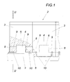
- Fig. 1
- einen erfindungsgemäßen Abstreifer in einer zum Teil aufgerissenen Vorderansicht und
- Fig. 2
- diesen Abstreifer in einem Schnitt nach der Linie II-II der
Fig. 1 in einem größeren Maßstab.
- Fig. 1
- a scraper according to the invention in a partially torn front view and
- Fig. 2
- this scraper in a section along the line II-II of the
Fig. 1 on a larger scale.
Der dargestellte Abstreifer umfasst einen Träger 1 und eine auf dem Träger 1 befestigte, biegeelastische Abstreifleiste 2, die sich aus einzelnen untereinander gleichen Leistenabschnitten 3 zusammensetzt. Zur Befestigung der Leistenabschnitte 3 auf dem Träger 1 weist dieser für jeden Leistenabschnitt 3 einen radial abstehenden, sich in Trägerlängsrichtung erstreckenden Befestigungsansatz 4 auf, wobei zur Konstruktionsvereinfachung die in Trägerlängsrichtung nebeneinandergereihten Befestigungsansätze 4 über einen gemeinsamen Steg 5 am Träger 1 angeschweißt sind. Die Leistenabschnitte 3 weisen Taschen 6 zur formschlüssigen Aufnahme der Steckansätze 4 auf und stützen sich zusätzlich über Stützflächen 7 beidseits der Befestigungsansätze 4 am Träger 1 ab, wie dies der
Zur Verriegelung der auf die Befestigungsansätze 4 aufgesteckten Leistenabschnitte 3 sind die Befestigungsansätze 4 auf ihren radialen Stirnseiten mit widerhakenartigen Rastkörpern 8 versehen, die in Rastaussparungen 9 auf der Breitseite der Taschen 6 eingreifen. Die widerhakenartigen Rastkörper 8 der Befestigungsansätze 4 weisen gemäß dem Ausführungsbeispiel nach der
Wie der
Um die auf die Befestigungsansätze 4 aufgesteckten Leistenabschnitte 3 der Abstreifleiste 2 wieder von den Befestigungsansätzen 4 lösen zu können, sind die Leistenabschnitte 3 mit quer zu den Befestigungsansätzen 4 und tangential zum Träger 5 verlaufenden Öffnungen 10 versehen, die einen Durchtritt über dem Träger 1 außerhalb der Befestigungsansätze 4 freigeben, wie dies insbesondere der
Wie aus den
Die Erfindung ist selbstverständlich nicht auf das dargestellte Ausführungsbeispiel beschränkt. So könnte anstelle einer Reihe von Leistenabschnitten 3 die Abstreifleiste 2 lediglich einen einzigen Abschnitt aufweisen, der mit gleichem Vorteil auf einen Befestigungsansatz 4 aufgesteckt werden kann.The invention is of course not limited to the illustrated embodiment. Thus, instead of a series of
Claims (3)
- Scraper for a conveyor belt having a support (1), extending transversely with respect to the conveyor belt, for a flexurally elastic scraping strip (2) preferably made from strip portions (3) which are disposed next to each other in the longitudinal direction of the support and which are placed on attachment protrusions (4) - which protrude radially from the support (1) and extend in the longitudinal direction of the support - and are secured on the attachment protrusions (4) via latching bodies (8) engaging in latching apertures (9), characterised in that the strip portions (3) form pockets (6) receiving the attachment protrusions (4) in a form-fitting manner, that the pockets (6), at least on a broad side, have latching apertures (9) for the latching bodies (8) provided on the radial end faces of the attachment protrusions (4), and that the strip portions (3) are provided on the side of the latching body (8) with openings (10) for insertion of a levering tool, these openings extending outside the attachment protrusions (4) tangentially with respect to the support (1) and transversely with respect to the attachment protrusions (4) and exposing a passage via the support (1).
- Scraper as claimed in claim 1, characterised in that, on both broad sides, the pockets (6) of the strip portions (3) have latching apertures (9) for the latching bodies (8) of the attachment protrusions (4) and that the latching apertures (9) are formed as through openings extending in the longitudinal direction of the support.
- Scraper as claimed in claim 1 or 2, characterised in that the openings (10) of the strip portions (3), which expose a passage via the support (1), are formed as grooves in the support surface (7) of the strip portions (3), which lies against the support (1).
Applications Claiming Priority (1)
| Application Number | Priority Date | Filing Date | Title |
|---|---|---|---|
| AT14002011A AT511583B1 (en) | 2011-09-28 | 2011-09-28 | SPREADER FOR A CONVEYOR BELT |
Publications (2)
| Publication Number | Publication Date |
|---|---|
| EP2574575A1 EP2574575A1 (en) | 2013-04-03 |
| EP2574575B1 true EP2574575B1 (en) | 2014-10-29 |
Family
ID=46832246
Family Applications (1)
| Application Number | Title | Priority Date | Filing Date |
|---|---|---|---|
| EP20120183320 Active EP2574575B1 (en) | 2011-09-28 | 2012-09-06 | Scraper for a conveyor belt |
Country Status (2)
| Country | Link |
|---|---|
| EP (1) | EP2574575B1 (en) |
| AT (1) | AT511583B1 (en) |
Family Cites Families (7)
| Publication number | Priority date | Publication date | Assignee | Title |
|---|---|---|---|---|
| US4598823A (en) | 1984-02-13 | 1986-07-08 | Martin Engineering Company | Conveyor belt cleaner |
| US5979638A (en) * | 1997-08-21 | 1999-11-09 | Argonics, Inc. | Conveyor belt wiper blade |
| DE19856338B4 (en) * | 1998-12-07 | 2004-09-30 | Ullrich Carsjens | Scraper for conveyor belts |
| GB0012881D0 (en) * | 2000-05-27 | 2000-07-19 | Horizon Gb Ltd | Conveyor belt scrapers |
| SE0103292L (en) * | 2001-10-03 | 2003-02-04 | Metso Minerals Trelleborg Ab | Scraper blade, especially conveyor belt scraper |
| JP4012208B2 (en) * | 2005-04-12 | 2007-11-21 | 日本通商株式会社 | Belt cleaner device |
| DE102007040435A1 (en) * | 2007-08-26 | 2009-03-05 | Ernst Meininger | Wiper, particularly dirt wiper, for wiping conveyor for application in wear-promoting conditions in mining industry, has two frameworks with carrying element and wiping element |
-
2011
- 2011-09-28 AT AT14002011A patent/AT511583B1/en active
-
2012
- 2012-09-06 EP EP20120183320 patent/EP2574575B1/en active Active
Also Published As
| Publication number | Publication date |
|---|---|
| AT511583A4 (en) | 2013-01-15 |
| AT511583B1 (en) | 2013-01-15 |
| EP2574575A1 (en) | 2013-04-03 |
Similar Documents
| Publication | Publication Date | Title |
|---|---|---|
| EP1881772B1 (en) | Broom body | |
| DE102013215823B4 (en) | Clip fastening device, in particular for motor vehicles | |
| DE102014001161A1 (en) | Holding device for long bodies, in particular for cables | |
| DE19607786A1 (en) | Connector for detachably mounting component in wall | |
| EP2574575B1 (en) | Scraper for a conveyor belt | |
| DE4323370C2 (en) | Profile strip made of insulating material for holding a large number of electrical cables | |
| DE102007025481A1 (en) | Frame part for a belt buckle of a safety belt | |
| DE7602860U1 (en) | Holder for cable ducts | |
| DE2236347B2 (en) | Modular sockets for electrical equipment - have tongue and groove construction with positive location end stop | |
| DE102005047933B4 (en) | Conveyor belt roller for belt conveyors, a conveyor belt and a belt conveyor dishwasher | |
| DE102006003780A1 (en) | Identification plate set | |
| DE202008013163U1 (en) | Substrate Carrier made of CFC (carbon fiber) for silicon wafers | |
| DE102013215787B4 (en) | Housing for an electrical connector, kit, connector and connector | |
| WO2009067728A1 (en) | Tie | |
| DE2706277A1 (en) | Resiliently supported sieve base - has grooves fitting onto headed resilient support members permitting bending for high rigidity | |
| DE10350465A1 (en) | Widening element for assembly strap for securing and wiring for electric units, especially in switchgear cubicles, with first integrally formed holder with U-shaped profile for strip-shaped strap edge section | |
| EP2754762A1 (en) | Drainage and/or fluid storage device for installation in the ground | |
| DE10314937B4 (en) | Plastic profile strip for holding a plurality of electrical lines | |
| AT505662B1 (en) | SPREADER FOR A CONVEYOR BELT | |
| EP1086325B1 (en) | Chain link for energy supply chains | |
| WO2000057079A1 (en) | Chain made of rod steel chain links | |
| EP1450069B1 (en) | Chain link for energy supply chain | |
| DE102007028820A1 (en) | Conveyor belt for use in conveyor device, particularly for glass manufacturing, is made of metal, with chain elements arranged one behind other in direction of travel | |
| DE2510177A1 (en) | Push fit plastic surface clamp - holds surfaces at required clearance and retains by plastic spring action | |
| EP3912934A1 (en) | Stripping element for a conveyor belt |
Legal Events
| Date | Code | Title | Description |
|---|---|---|---|
| PUAI | Public reference made under article 153(3) epc to a published international application that has entered the european phase |
Free format text: ORIGINAL CODE: 0009012 |
|
| AK | Designated contracting states |
Kind code of ref document: A1 Designated state(s): AL AT BE BG CH CY CZ DE DK EE ES FI FR GB GR HR HU IE IS IT LI LT LU LV MC MK MT NL NO PL PT RO RS SE SI SK SM TR |
|
| AX | Request for extension of the european patent |
Extension state: BA ME |
|
| 17P | Request for examination filed |
Effective date: 20130712 |
|
| RBV | Designated contracting states (corrected) |
Designated state(s): AL AT BE BG CH CY CZ DE DK EE ES FI FR GB GR HR HU IE IS IT LI LT LU LV MC MK MT NL NO PL PT RO RS SE SI SK SM TR |
|
| GRAP | Despatch of communication of intention to grant a patent |
Free format text: ORIGINAL CODE: EPIDOSNIGR1 |
|
| INTG | Intention to grant announced |
Effective date: 20140602 |
|
| GRAS | Grant fee paid |
Free format text: ORIGINAL CODE: EPIDOSNIGR3 |
|
| GRAA | (expected) grant |
Free format text: ORIGINAL CODE: 0009210 |
|
| AK | Designated contracting states |
Kind code of ref document: B1 Designated state(s): AL AT BE BG CH CY CZ DE DK EE ES FI FR GB GR HR HU IE IS IT LI LT LU LV MC MK MT NL NO PL PT RO RS SE SI SK SM TR |
|
| REG | Reference to a national code |
Ref country code: GB Ref legal event code: FG4D Free format text: NOT ENGLISH |
|
| REG | Reference to a national code |
Ref country code: CH Ref legal event code: EP |
|
| REG | Reference to a national code |
Ref country code: AT Ref legal event code: REF Ref document number: 693465 Country of ref document: AT Kind code of ref document: T Effective date: 20141115 |
|
| REG | Reference to a national code |
Ref country code: IE Ref legal event code: FG4D Free format text: LANGUAGE OF EP DOCUMENT: GERMAN |
|
| REG | Reference to a national code |
Ref country code: DE Ref legal event code: R096 Ref document number: 502012001494 Country of ref document: DE Effective date: 20141211 |
|
| REG | Reference to a national code |
Ref country code: NL Ref legal event code: VDEP Effective date: 20141029 |
|
| REG | Reference to a national code |
Ref country code: LT Ref legal event code: MG4D |
|
| PG25 | Lapsed in a contracting state [announced via postgrant information from national office to epo] |
Ref country code: LT Free format text: LAPSE BECAUSE OF FAILURE TO SUBMIT A TRANSLATION OF THE DESCRIPTION OR TO PAY THE FEE WITHIN THE PRESCRIBED TIME-LIMIT Effective date: 20141029 Ref country code: ES Free format text: LAPSE BECAUSE OF FAILURE TO SUBMIT A TRANSLATION OF THE DESCRIPTION OR TO PAY THE FEE WITHIN THE PRESCRIBED TIME-LIMIT Effective date: 20141029 Ref country code: IS Free format text: LAPSE BECAUSE OF FAILURE TO SUBMIT A TRANSLATION OF THE DESCRIPTION OR TO PAY THE FEE WITHIN THE PRESCRIBED TIME-LIMIT Effective date: 20150228 Ref country code: NL Free format text: LAPSE BECAUSE OF FAILURE TO SUBMIT A TRANSLATION OF THE DESCRIPTION OR TO PAY THE FEE WITHIN THE PRESCRIBED TIME-LIMIT Effective date: 20141029 Ref country code: PT Free format text: LAPSE BECAUSE OF FAILURE TO SUBMIT A TRANSLATION OF THE DESCRIPTION OR TO PAY THE FEE WITHIN THE PRESCRIBED TIME-LIMIT Effective date: 20150302 Ref country code: FI Free format text: LAPSE BECAUSE OF FAILURE TO SUBMIT A TRANSLATION OF THE DESCRIPTION OR TO PAY THE FEE WITHIN THE PRESCRIBED TIME-LIMIT Effective date: 20141029 Ref country code: NO Free format text: LAPSE BECAUSE OF FAILURE TO SUBMIT A TRANSLATION OF THE DESCRIPTION OR TO PAY THE FEE WITHIN THE PRESCRIBED TIME-LIMIT Effective date: 20150129 |
|
| PG25 | Lapsed in a contracting state [announced via postgrant information from national office to epo] |
Ref country code: LV Free format text: LAPSE BECAUSE OF FAILURE TO SUBMIT A TRANSLATION OF THE DESCRIPTION OR TO PAY THE FEE WITHIN THE PRESCRIBED TIME-LIMIT Effective date: 20141029 Ref country code: GR Free format text: LAPSE BECAUSE OF FAILURE TO SUBMIT A TRANSLATION OF THE DESCRIPTION OR TO PAY THE FEE WITHIN THE PRESCRIBED TIME-LIMIT Effective date: 20150130 Ref country code: RS Free format text: LAPSE BECAUSE OF FAILURE TO SUBMIT A TRANSLATION OF THE DESCRIPTION OR TO PAY THE FEE WITHIN THE PRESCRIBED TIME-LIMIT Effective date: 20141029 Ref country code: PL Free format text: LAPSE BECAUSE OF FAILURE TO SUBMIT A TRANSLATION OF THE DESCRIPTION OR TO PAY THE FEE WITHIN THE PRESCRIBED TIME-LIMIT Effective date: 20141029 Ref country code: CY Free format text: LAPSE BECAUSE OF FAILURE TO SUBMIT A TRANSLATION OF THE DESCRIPTION OR TO PAY THE FEE WITHIN THE PRESCRIBED TIME-LIMIT Effective date: 20141029 Ref country code: SE Free format text: LAPSE BECAUSE OF FAILURE TO SUBMIT A TRANSLATION OF THE DESCRIPTION OR TO PAY THE FEE WITHIN THE PRESCRIBED TIME-LIMIT Effective date: 20141029 Ref country code: HR Free format text: LAPSE BECAUSE OF FAILURE TO SUBMIT A TRANSLATION OF THE DESCRIPTION OR TO PAY THE FEE WITHIN THE PRESCRIBED TIME-LIMIT Effective date: 20141029 |
|
| REG | Reference to a national code |
Ref country code: DE Ref legal event code: R097 Ref document number: 502012001494 Country of ref document: DE |
|
| PG25 | Lapsed in a contracting state [announced via postgrant information from national office to epo] |
Ref country code: RO Free format text: LAPSE BECAUSE OF FAILURE TO SUBMIT A TRANSLATION OF THE DESCRIPTION OR TO PAY THE FEE WITHIN THE PRESCRIBED TIME-LIMIT Effective date: 20141029 Ref country code: SK Free format text: LAPSE BECAUSE OF FAILURE TO SUBMIT A TRANSLATION OF THE DESCRIPTION OR TO PAY THE FEE WITHIN THE PRESCRIBED TIME-LIMIT Effective date: 20141029 Ref country code: DK Free format text: LAPSE BECAUSE OF FAILURE TO SUBMIT A TRANSLATION OF THE DESCRIPTION OR TO PAY THE FEE WITHIN THE PRESCRIBED TIME-LIMIT Effective date: 20141029 Ref country code: CZ Free format text: LAPSE BECAUSE OF FAILURE TO SUBMIT A TRANSLATION OF THE DESCRIPTION OR TO PAY THE FEE WITHIN THE PRESCRIBED TIME-LIMIT Effective date: 20141029 Ref country code: EE Free format text: LAPSE BECAUSE OF FAILURE TO SUBMIT A TRANSLATION OF THE DESCRIPTION OR TO PAY THE FEE WITHIN THE PRESCRIBED TIME-LIMIT Effective date: 20141029 |
|
| PG25 | Lapsed in a contracting state [announced via postgrant information from national office to epo] |
Ref country code: IT Free format text: LAPSE BECAUSE OF FAILURE TO SUBMIT A TRANSLATION OF THE DESCRIPTION OR TO PAY THE FEE WITHIN THE PRESCRIBED TIME-LIMIT Effective date: 20141029 |
|
| PLBE | No opposition filed within time limit |
Free format text: ORIGINAL CODE: 0009261 |
|
| STAA | Information on the status of an ep patent application or granted ep patent |
Free format text: STATUS: NO OPPOSITION FILED WITHIN TIME LIMIT |
|
| REG | Reference to a national code |
Ref country code: FR Ref legal event code: PLFP Year of fee payment: 4 |
|
| 26N | No opposition filed |
Effective date: 20150730 |
|
| PG25 | Lapsed in a contracting state [announced via postgrant information from national office to epo] |
Ref country code: SI Free format text: LAPSE BECAUSE OF FAILURE TO SUBMIT A TRANSLATION OF THE DESCRIPTION OR TO PAY THE FEE WITHIN THE PRESCRIBED TIME-LIMIT Effective date: 20141029 |
|
| PG25 | Lapsed in a contracting state [announced via postgrant information from national office to epo] |
Ref country code: LU Free format text: LAPSE BECAUSE OF FAILURE TO SUBMIT A TRANSLATION OF THE DESCRIPTION OR TO PAY THE FEE WITHIN THE PRESCRIBED TIME-LIMIT Effective date: 20150906 Ref country code: MC Free format text: LAPSE BECAUSE OF FAILURE TO SUBMIT A TRANSLATION OF THE DESCRIPTION OR TO PAY THE FEE WITHIN THE PRESCRIBED TIME-LIMIT Effective date: 20141029 |
|
| REG | Reference to a national code |
Ref country code: CH Ref legal event code: PL |
|
| REG | Reference to a national code |
Ref country code: IE Ref legal event code: MM4A |
|
| PG25 | Lapsed in a contracting state [announced via postgrant information from national office to epo] |
Ref country code: IE Free format text: LAPSE BECAUSE OF NON-PAYMENT OF DUE FEES Effective date: 20150906 Ref country code: CH Free format text: LAPSE BECAUSE OF NON-PAYMENT OF DUE FEES Effective date: 20150930 Ref country code: LI Free format text: LAPSE BECAUSE OF NON-PAYMENT OF DUE FEES Effective date: 20150930 |
|
| REG | Reference to a national code |
Ref country code: FR Ref legal event code: PLFP Year of fee payment: 5 |
|
| PG25 | Lapsed in a contracting state [announced via postgrant information from national office to epo] |
Ref country code: MT Free format text: LAPSE BECAUSE OF FAILURE TO SUBMIT A TRANSLATION OF THE DESCRIPTION OR TO PAY THE FEE WITHIN THE PRESCRIBED TIME-LIMIT Effective date: 20141029 |
|
| GBPC | Gb: european patent ceased through non-payment of renewal fee |
Effective date: 20160906 |
|
| PG25 | Lapsed in a contracting state [announced via postgrant information from national office to epo] |
Ref country code: HU Free format text: LAPSE BECAUSE OF FAILURE TO SUBMIT A TRANSLATION OF THE DESCRIPTION OR TO PAY THE FEE WITHIN THE PRESCRIBED TIME-LIMIT; INVALID AB INITIO Effective date: 20120906 Ref country code: BG Free format text: LAPSE BECAUSE OF FAILURE TO SUBMIT A TRANSLATION OF THE DESCRIPTION OR TO PAY THE FEE WITHIN THE PRESCRIBED TIME-LIMIT Effective date: 20141029 Ref country code: SM Free format text: LAPSE BECAUSE OF FAILURE TO SUBMIT A TRANSLATION OF THE DESCRIPTION OR TO PAY THE FEE WITHIN THE PRESCRIBED TIME-LIMIT Effective date: 20141029 |
|
| PG25 | Lapsed in a contracting state [announced via postgrant information from national office to epo] |
Ref country code: BE Free format text: LAPSE BECAUSE OF NON-PAYMENT OF DUE FEES Effective date: 20150930 Ref country code: GB Free format text: LAPSE BECAUSE OF NON-PAYMENT OF DUE FEES Effective date: 20160906 |
|
| PG25 | Lapsed in a contracting state [announced via postgrant information from national office to epo] |
Ref country code: TR Free format text: LAPSE BECAUSE OF FAILURE TO SUBMIT A TRANSLATION OF THE DESCRIPTION OR TO PAY THE FEE WITHIN THE PRESCRIBED TIME-LIMIT Effective date: 20141029 |
|
| REG | Reference to a national code |
Ref country code: FR Ref legal event code: PLFP Year of fee payment: 6 |
|
| PG25 | Lapsed in a contracting state [announced via postgrant information from national office to epo] |
Ref country code: MK Free format text: LAPSE BECAUSE OF FAILURE TO SUBMIT A TRANSLATION OF THE DESCRIPTION OR TO PAY THE FEE WITHIN THE PRESCRIBED TIME-LIMIT Effective date: 20141029 |
|
| REG | Reference to a national code |
Ref country code: FR Ref legal event code: PLFP Year of fee payment: 7 |
|
| PG25 | Lapsed in a contracting state [announced via postgrant information from national office to epo] |
Ref country code: AL Free format text: LAPSE BECAUSE OF FAILURE TO SUBMIT A TRANSLATION OF THE DESCRIPTION OR TO PAY THE FEE WITHIN THE PRESCRIBED TIME-LIMIT Effective date: 20141029 |
|
| REG | Reference to a national code |
Ref country code: AT Ref legal event code: MM01 Ref document number: 693465 Country of ref document: AT Kind code of ref document: T Effective date: 20170906 |
|
| PG25 | Lapsed in a contracting state [announced via postgrant information from national office to epo] |
Ref country code: AT Free format text: LAPSE BECAUSE OF NON-PAYMENT OF DUE FEES Effective date: 20170906 |
|
| P01 | Opt-out of the competence of the unified patent court (upc) registered |
Effective date: 20230323 |
|
| PGFP | Annual fee paid to national office [announced via postgrant information from national office to epo] |
Ref country code: FR Payment date: 20230926 Year of fee payment: 12 Ref country code: DE Payment date: 20230928 Year of fee payment: 12 |