EP2574227B1 - Selbstfahrende Erntemaschine - Google Patents
Selbstfahrende Erntemaschine Download PDFInfo
- Publication number
- EP2574227B1 EP2574227B1 EP20120175222 EP12175222A EP2574227B1 EP 2574227 B1 EP2574227 B1 EP 2574227B1 EP 20120175222 EP20120175222 EP 20120175222 EP 12175222 A EP12175222 A EP 12175222A EP 2574227 B1 EP2574227 B1 EP 2574227B1
- Authority
- EP
- European Patent Office
- Prior art keywords
- brake
- self
- propelled harvester
- drum
- harvester
- Prior art date
- Legal status (The legal status is an assumption and is not a legal conclusion. Google has not performed a legal analysis and makes no representation as to the accuracy of the status listed.)
- Active
Links
- 239000000463 material Substances 0.000 claims description 5
- 238000003306 harvesting Methods 0.000 description 9
- 238000004140 cleaning Methods 0.000 description 7
- 239000010902 straw Substances 0.000 description 6
- 239000004459 forage Substances 0.000 description 5
- 230000010354 integration Effects 0.000 description 4
- 238000010276 construction Methods 0.000 description 3
- 241001124569 Lycaenidae Species 0.000 description 2
- 230000007797 corrosion Effects 0.000 description 2
- 238000005260 corrosion Methods 0.000 description 2
- 238000011161 development Methods 0.000 description 2
- 230000018109 developmental process Effects 0.000 description 2
- 238000009825 accumulation Methods 0.000 description 1
- 230000008878 coupling Effects 0.000 description 1
- 238000010168 coupling process Methods 0.000 description 1
- 238000005859 coupling reaction Methods 0.000 description 1
- 230000001419 dependent effect Effects 0.000 description 1
- 230000007613 environmental effect Effects 0.000 description 1
- 238000009434 installation Methods 0.000 description 1
Images


Classifications
-
- A—HUMAN NECESSITIES
- A01—AGRICULTURE; FORESTRY; ANIMAL HUSBANDRY; HUNTING; TRAPPING; FISHING
- A01D—HARVESTING; MOWING
- A01D41/00—Combines, i.e. harvesters or mowers combined with threshing devices
- A01D41/12—Details of combines
- A01D41/14—Mowing tables
- A01D41/142—Header drives
-
- A—HUMAN NECESSITIES
- A01—AGRICULTURE; FORESTRY; ANIMAL HUSBANDRY; HUNTING; TRAPPING; FISHING
- A01D—HARVESTING; MOWING
- A01D75/00—Accessories for harvesters or mowers
- A01D75/18—Safety devices for parts of the machines
- A01D75/187—Removing foreign objects
-
- A—HUMAN NECESSITIES
- A01—AGRICULTURE; FORESTRY; ANIMAL HUSBANDRY; HUNTING; TRAPPING; FISHING
- A01F—PROCESSING OF HARVESTED PRODUCE; HAY OR STRAW PRESSES; DEVICES FOR STORING AGRICULTURAL OR HORTICULTURAL PRODUCE
- A01F12/00—Parts or details of threshing apparatus
- A01F12/10—Feeders
- A01F12/16—Safety devices
-
- A—HUMAN NECESSITIES
- A01—AGRICULTURE; FORESTRY; ANIMAL HUSBANDRY; HUNTING; TRAPPING; FISHING
- A01F—PROCESSING OF HARVESTED PRODUCE; HAY OR STRAW PRESSES; DEVICES FOR STORING AGRICULTURAL OR HORTICULTURAL PRODUCE
- A01F29/00—Cutting apparatus specially adapted for cutting hay, straw or the like
- A01F29/09—Details
- A01F29/16—Safety devices, e.g. emergency brake arrangements
Definitions
- the present invention relates to a self-propelled harvesting machine according to the preamble of claim 1.
- Self-propelled harvesting machines are equipped with a collection device arranged in the front region of the harvesting machine, which serves to feed harvested crop picked up by a harvesting device attachable to the collection device into the harvesting machine for further processing thereof.
- the Erntegutabilityvorides is driven by a arranged on the feeder drive shaft and braked by a braking device.
- Such a harvester is from the DE 199 40 467 A1 known.
- an agricultural harvesting machine having a feeder to which a Erntegutagevoriques is attachable.
- the drive of the inclined conveyor as well as the Erntegutabilityvoriques takes place through the harvester and is separated therefrom by a coupling which is arranged at a first end of the upper sprocket of the inclined conveyor.
- a pulley is fixed, which drives a belt pulley on a lower sprocket of the inclined conveyor by means of a belt.
- the lower sprocket is associated with a hydraulically actuated disc brake, which causes a shutdown of Erntegut applicationvortechnisch.
- the braking device is designed as a drum brake with a brake drum, in which at least one additional function is integrated.
- the closed construction of a drum brake prevents the occurrence of flying sparks, which can significantly reduce the risk of fire.
- a drum brake is less susceptible to corrosion.
- the additional function in the reversing function of the collection device and the Erntegutagevoriques exist.
- the reversing function of the drive of the collection device and the Erntegutavoriques is necessary in order to be able to eliminate this in a Gutstau occurring in the Erntegutavorplatz and / or the collection device.
- the brake device may have a bearing flange, which serves as a shaft bearing and the inclusion of the components of the braking device.
- the constructive core of the brake device forming bearing flange contributes significantly to the desired functional integration and allows universal applicability of the braking device on both combine harvesters and forage harvesters.
- the brake device can be controlled by a hydraulically loadable brake cylinder.
- a quick response of the braking device can be achieved.
- the integration in the already existing on the feeder hydraulic circuit is also inexpensive.
- a gear formed on the brake drum can be provided as reversing drive, which can be brought into engagement with a pinion actuatable by a hydraulic cylinder for the reversing function.
- the reversing function is used in the event of a blockage of the harvesting material receiving device and / or the collection device in order to convey out crop material which blocks the harvested crop receiving device and / or the collection device.
- the brake device can be arranged at the end of a drive train driving the intake device.
- the arrangement should take place in the immediate vicinity of the units to be braked.
- a quick and direct braking of the collection device and the Erntegutavoriques can be achieved.
- the load on the drive train is significantly reduced by this arrangement, since an introduction of shear forces is eliminated.
- the additional function in the embodiment of the brake drum can consist of a drive element.
- the drive element may be designed as a molded onto the brake drum pulley.
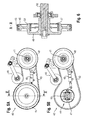
- the in Fig. 1 Combine 1 shown schematically consists of a support frame connected to the chassis, on which a multi-part machine housing 22 is attached.
- a closed cab 23 is arranged in the front area.
- the combine harvester 1 picks up a crop collecting device in the form of a grain cutting unit 2, which is connected in a manner known per se to a collection device in the form of an inclined conveyor 4 on the combine harvester 1.
- the cross conveyor 3 of the cutting unit 2 passes the crop to the feeder 4, which passes the crop through a revolving chain conveyor 5 in its top-rear region to the threshing unit 6 of the combine 1.
- the crop is passed between the threshing drum 7 and a threshing concave 8 which at least partly covers it and is separated into at least two partial streams 9, 10.
- the first partial flow 9 consists essentially of grains, short straw and chaff and is fed via a preparation tray 11 directly to a cleaning device 13 consisting of different screen planes 12.
- the cleaning device 13 also adopts a cleaning fan 14, which generates an airflow passing through the wire planes 12.
- FIG. 2 shows a side view of the feed device of the combine harvester 1 designed as an inclined conveyor 4 according to Fig. 1 ,
- the inclined conveyor 4 is arranged with one end on the combine 1 while the opposite end of the recording of the cutting unit 2 is used.
- the inclined conveyor 4 driven shafts which are respectively arranged in end portions of the inclined conveyor 4 transverse to its longitudinal axis.
- the position of a first, the drive of the inclined conveyor 4 serving shaft through an opening 30 in the side wall of the inclined conveyor 4 is indicated.
- the opposite end region is located one of the reversing of the inclined conveyor 4 and the cutting unit 2 serving reversing device 31.
- the reversing device 31 serving to perform the reversing function comprises a lever assembly 32 which is hydraulically actuated, and a gear 51, which in Fig. 4 is shown.
- the reversing device 31 interacts with its operation with a braking device 33, in which at least one additional function is integrated.
- a braking device 33 in which at least one additional function is integrated.
- a reversing of the inclined conveyor 4 and the cutting unit 2 to achieve a Gutstau reach.
- the drum brake 34 is as shown in the detail view Fig. 3 can be actuated by a hydraulic actuator 37 operable to brake the drive of the cutting unit 2 serving shaft as quickly as possible, for example, if foreign objects could be absorbed by the cutting unit 2, which could lead to damage to the cutting unit 2 or to the working elements of the combine 1.
- the arrangement of the braking device 33 in the immediate vicinity of the cutting unit 2 is advantageous in that the cutting unit 2 can be braked faster and more directly.
- Fig. 4 is a sectional view of the braking device 33 along the line II-II shown. This view is the internal structure of the brake device 33 can be seen.
- the braking device 33 is arranged by means of a bearing flange 39 on a transverse to the longitudinal direction of the inclined conveyor 4 extending shaft 38.
- the bearing flange 39 is used in addition to the arrangement of the braking device 33 on the shaft 38 and the inclusion of the individual components of the braking device 33, such as the drum brake 34, and also forms the brake drum 35 and the formed on the brake drum 35 gear 36 from.
- the integration of many different functionalities in a single component leads to a high functional density and, consequently, to a space-saving design. Along with this, the assembly effort also drops.
- the illustration shows a gear 51, which can be brought by the indicated hydraulic drive with the gear 36 on the brake drum 35 in engagement to achieve reversing the drive of the inclined conveyor 4 and the cutting unit 2 when a crop accumulation occurs in them.
- the representations in the Figs. 5A and 5B each show a side view of a drive device 40 for a collection device of a self-propelled forage harvester, which can also be used on a combine harvester.
- Guided by two pulleys 42, 45 runs a belt 43, which serves to transmit a torque to the aggregates of the collection device.
- the torque is provided by a motor arranged in the rear region of the self-propelled forage harvester and transmitted via a first, not shown belt drive on a shaft 41 carrying the cutterhead and from there via the attached to the shaft 41 pulley 42 to the collection device.
- the belt 43 is acted upon by a tensioning device 46 provided with a hydraulically actuable pressure roller.
- the tensioning device 46 is used as a clutch to release the bias applied to the belt 43 from the tension pulley in the case of a quick stop of the drive device 40, whereby the belt 43 can slip.
- a braking device 44 is visible, which includes the pulley 45 as a component.
- the brake device 44 is designed as a drum brake 47, on the brake drum, the pulley 45 is formed.
- the drum brake 47 is, as already above has been described, hydraulically actuated.
- a hydraulic actuatable actuator 48 is arranged on the intake device of the forage harvester.
- the representation according to Fig. 6 shows a sectional view taken along the line VV according to Fig. 5A , From this illustration, the internal structure of the brake device 44 with integrated additional function can be seen.
- the brake device 44 is supported on a shaft 50 supported by a bearing flange 49.
- the bearing flange 49 also carries all components of the braking device 44 and forms its brake drum 52 in this exemplary embodiment.
- the bearing flange 49 differs from that bearing flange 39, the part of the braking device 33 on the inclined conveyor 4 of the combine harvester 1 is characterized in that a pulley 45 is formed on the brake drum 52 instead of a formed on the brake drum 35 gear 36, to take over the additional function of a drive means.
Description
- Die vorliegende Erfindung betrifft eine selbstfahrende Erntemaschine gemäß dem Oberbegriff des Anspruches 1.
- Selbstfahrende Erntemaschinen sind mit einer im frontseitigen Bereich der Erntemaschine angeordneten Einzugsvorrichtung ausgestattet, die der Zuführung von einer an der Einzugsvorrichtung anbringbaren Erntegutaufnahmevorrichtung aufgenommenem Erntegut in die Erntemaschine zu dessen weiterer Verarbeitung dient. Die Erntegutaufnahmevorrichtung ist von einer an der Einzugsvorrichtung angeordneten Antriebswelle antreibbar und durch eine Bremsvorrichtung abbremsbar.
- Eine derartige Erntemaschine ist aus der
DE 199 40 467 A1 bekannt. Darin ist eine landwirtschaftliche Erntemaschine beschrieben, die einen Schrägförderer aufweist, an dem eine Erntegutaufnahmevorrichtung anbringbar ist. Der Antrieb des Schrägförderers wie auch der Erntegutaufnahmevorrichtung erfolgt durch die Erntemaschine und ist von dieser durch eine Kupplung abtrennbar, die an einem ersten Ende der oberen Kettenradwelle des Schrägförderers angeordnet ist. An einem zweiten Ende der oberen Kettenradwelle ist eine Riemenscheibe befestigt, die durch einen Riemen eine Riemenscheibe an einer unteren Kettenradwelle des Schrägförderers treibt. Der unteren Kettenradwelle ist eine hydraulisch betätigbare Scheibenbremse zugeordnet, die ein Stillsetzen der Erntegutaufnahmevorrichtung bewirkt. - Als problematisch an der aus der
DE 199 40 467 A1 bekannten Lösung ist der Einsatz einer Scheibenbremse anzusehen, da durch Funkenflug eine erhöhte Brandgefahr besteht. Zudem lässt dieDE 199 40 467 A1 offen, wie der Bremsenaufbau im Detail aussehen könnte, insbesondere vor dem Hintergrund eines raum- und gewichtsoptimierten Aufbaus der Bremsvorrichtung. Weiterhin tritt bei einer freiliegenden Bremsscheibe das Problem der Korrosion auf, welche zu einer Verlängerung der Bremszeit führt, was insbesondere in Situationen, in denen eine schnellstmögliche Stillsetzung der Erntegutaufnahmevorrichtung erforderlich ist, Schäden an der Erntemaschine durch in diese eingebrachte Fremdkörper nach sich ziehen kann. Auch dieEP 1064834 A1 offenbart eine freiliegende Scheibenbremse für den Schrägförderer gemäß Oberbegriff des Anspruchs 1. - Daher ist es Aufgabe der vorliegenden Erfindung, eine selbstfahrende Erntemaschine der eingangs genannten Art bereitzustellen, durch die die zuvor genannten Nachteile vermeidbar sind.
- Die Aufgabe wird erfindungsgemäß durch die kennzeichnenden Merkmale des Anspruches 1 gelöst.
- Vorteilhafte Weiterbildungen der selbstfahrenden Erntemaschine sind Gegenstand der Unteransprüche.
- Gemäß Anspruch 1 wird vorgeschlagen, dass die Bremsvorrichtung als Trommelbremse mit einer Bremstrommel ausgeführt ist, in die zumindest eine Zusatzfunktion integriert ist. Der geschlossene Aufbau einer Trommelbremse verhindert das Auftreten von Funkenflug, wodurch die Brandgefahr deutlich verringert werden kann. Ebenso ist eine Trommelbremse weniger korrosionsanfällig. Durch die Integration zumindest einer Zusatzfunktion in die Bremstrommel der Trommelbremse wird der Anforderung an den raum- und gewichtsoptimierten Aufbau der Bremsvorrichtung an der Einzugsvorrichtung Rechnung getragen. Zudem reduziert die Integration einer Zusatzfunktion in die Bremsvorrichtung den erforderlichen Montageaufwand.
- Vorzugsweise kann die Zusatzfunktion in der Reversierfunktion der Einzugsvorrichtung und der Erntegutaufnahmevorrichtung bestehen. Die Reversierfunktion des Antriebes der Einzugsvorrichtung sowie der Erntegutaufnahmevorrichtung ist notwendig, um bei einem auftretenden Gutstau in der Erntegutaufnahmevorrichtung und/oder der Einzugsvorrichtung diesen beseitigen zu können.
- Weiterhin kann die Bremsvorrichtung einen Lagerflansch aufweisen, der als Wellenlagerung und der Aufnahme der Komponenten der Bremsvorrichtung dient. Der den konstruktiven Kern der Bremsvorrichtung bildende Lagerflansch trägt maßgeblich zu der angestrebten Funktionsintegration bei und ermöglicht eine universelle Einsetzbarkeit der Bremsvorrichtung sowohl an Mähdreschern als auch an Feldhäckslern.
- Insbesondere kann die Bremsvorrichtung durch einen hydraulisch beaufschlagbaren Bremszylinder ansteuerbar sein. Somit ist ein schnelles Ansprechen der Bremsvorrichtung erreichbar. Die Integration in den an der Einzugsvorrichtung bereits vorhandenen Hydraulikkreislauf ist zudem kostengünstig.
- Des Weiteren kann als Reversierantrieb ein auf die Bremstrommel aufgeformtes Zahnrad vorgesehen sein, welches für die Reversierfunktion mit einem durch einen Hydraulikzylinder betätigbares Ritzel in Eingriff bringbar ist. Die Reversierfunktion kommt bei einer Verstopfung der Erntegutaufnahmevorrichtung und/oder der Einzugsvorrichtung zum Einsatz, um Erntegut, welches die Erntegutaufnahmevorrichtung und/oder die Einzugsvorrichtung blockiert, aus diesen hinauszubefördern.
- Vorteilhafterweise kann die Bremsvorrichtung am Ende eines die Einzugsvorrichtung antreibenden Antriebsstranges angeordnet sein. Hierbei sollte die Anordnung in unmittelbarer Nähe zu den abzubremsenden Aggregaten erfolgen. Dadurch lässt sich ein schnelles und direktes Abbremsen der Einzugsvorrichtung sowie der Erntegutaufnahmevorrichtung erreichen. Zudem wird durch diese Anordnung die Belastung des Antriebsstranges deutlich reduziert, da eine Einleitung von Querkräften entfällt.
- In bevorzugter Weiterbildung kann die Zusatzfunktion in der Ausführung der Bremstrommel als ein Antriebselement bestehen.
- Hierzu kann das Antriebselement als eine auf die Bremstrommel aufgeformte Riemenscheibe ausgeführt sein.
- Die Erfindung wird nachstehend an in den Zeichnungen dargestellten Ausführungsbeispielen näher erläutert.
- In den zugehörigen Zeichnungen zeigen:
- Fig. 1
- eine schematische Seitenansicht eines Mähdreschers;
- Fig. 2
- eine Seitenansicht einer Einzugsvorrichtung des Mähdreschers gemäß
Fig. 1 ; - Fig. 3
- eine Detailansicht einer Bremsvorrichtung der Einzugsvorrichtung;
- Fig. 4
- eine Schnittansicht entlang der Linie II-II gemäß
Fig. 2 ; - Fig. 5
- eine Seitenansicht einer Antriebsvorrichtung für eine Einzugsvorrichtung;
- Fig. 6
- eine Schnittansicht entlang der Linie V-V gemäß
Fig. 5 ; - Der in
Fig. 1 schematisch dargestellte Mähdrescher 1 besteht aus einem mit dem Fahrwerk verbundenen Traggestell, auf dem ein mehrteiliges Maschinengehäuse 22 befestigt ist. Um den Fahrer des Mähdreschers 1 vor belastenden Umwelteinflüssen zu schützen, ist im frontseitigen Bereich eine geschlossene Fahrerkabine 23 angeordnet. Der Mähdrescher 1 nimmt eine Erntegutaufnahmevorrichtung in Form eines Getreideschneidwerkes 2 auf, welches in an sich bekannter Weise mit einer Einzugsvorrichtung in Form eines Schrägförderers 4 an dem Mähdrescher 1 verbunden ist. Das Querförderorgan 3 des Schneidwerkes 2 übergibt das Erntegut an den Schrägförderer 4, wobei dieser das Erntegut durch einen umlaufenden Kettenförderer 5 in seinem obenseitigen rückwärtigen Bereich an das Dreschwerk 6 des Mähdreschers 1 übergibt. In dem Dreschwerk 6 wird das Erntegut zwischen der Dreschtrommel 7 und einem diese wenigstens teilweise ummantelnden Dreschkorb 8 hindurchgeführt und in zumindest zwei Teilströme 9, 10 getrennt. Der erste Teilstrom 9 besteht im Wesentlichen aus Körnern, Kurzstroh und Spreu und wird über einen Vorbereitungsboden 11 unmittelbar einer aus verschiedenen Siebebenen 12 bestehenden Reinigungseinrichtung 13 zugeführt. Die Reinigungseinrichtung 13 nimmt zudem ein Reinigungsgebläse 14 auf, das einen die Siebebenen 12 durchsetzenden Luftstrom generiert. - Der im rückwärtigen Bereich des Dreschwerks 6 aus diesem austretende Teilstrom 10, der im Wesentlichen aus Stroh und einem Restkornanteil besteht. wird durch eine Strohleittrommel 15 auf ein als Hordenschüttler 16 ausgeführtes Abscheideorgan 17 geleitet. Durch die Bewegung des Hordenschüttlers 16 wird ein großer Anteil der in der Strohschicht enthaltenen Körner auf dem Hordenschüttler 16 abgeschieden und über einen sogenannten Rücklaufboden 18 und den Vorbereitungsboden 11 an die Reinigungseinrichtung 13 übergeben. In der Reinigungseinrichtung 13 wird schließlich aus den in sie eingeleiteten verschiedenen Gutströmen ein gereinigter Körnerstrom durch eine Fördereinrichtung 23 in einen Korntank 20 gefördert und dort zwischengespeichert. Die Entleerung des Korntanks 20 erfolgt in der Regel mittels eines Korntankentleerförderers 21.
- Die Darstellung in
Fig. 2 zeigt eine Seitenansicht der als Schrägförderer 4 ausgeführten Einzugsvorrichtung des Mähdreschers 1 gemäßFig. 1 . Der Schrägförderer 4 ist mit einem Ende am Mähdrescher 1 angeordnet während das gegenüberliegende Ende der Aufnahme des Schneidwerkes 2 dient. Für das Antreiben des Schrägförderers 4 sowie des Schneidwerkes 2 weist der Schrägförderer 4 antreibbare Wellen auf, die jeweils in Endbereichen des Schrägförderers 4 quer zu dessen Längsachse angeordnet sind. In dem dem Mähdrescher 1 zugewandten Endbereich des Schrägförderers 4 ist die Position einer ersten, dem Antrieb des Schrägförderers 4 dienende Welle durch eine Öffnung 30 in der Seitenwand der Schrägförderers 4 angedeutet. In dem gegenüberliegenden Endbereich befindet sich eine der Reversierung des Schrägförderers 4 und des Schneidwerkes 2 dienende Reversiervorrichtung 31. Die zur Ausführung der Reversierfunktion dienende Reversiervorrichtung 31 umfasst eine Hebelanordnung 32, die hydraulisch betätigbar ist, sowie ein Zahnrad 51, welches inFig. 4 dargestellt ist. Die Reversiervorrichtung 31 wirkt bei ihrer Betätigung mit einer Bremsvorrichtung 33 zusammen, in die zumindest eine Zusatzfunktion integriert ist. In dem inFig. 2 dargestellten Ausführungsbeispiel weist die als Trommelbremse 34 mit einer Bremstrommel 35 ausgeführte Bremsvorrichtung 33 ein auf der Bremstrommel 35 aufgeformtes Zahnrad 36 auf, welches mit dem Zahnrad 51 an der Hebelanordnung 32 der Reversiervorrichtung 31 in Eingriff bringbar ist, um ein Reversieren des Schrägförderers 4 sowie des Schneidwerkes 2 zur Behebung eines Gutstaues zu erreichen. - Die Trommelbremse 34 ist, wie aus der Detailansicht gemäß
Fig. 3 ersichtlich ist, durch einen hydraulischen Aktor 37 betätigbar, um die dem Antrieb des Schneidwerkes 2 dienende Welle schnellstmöglich abzubremsen, wenn beispielsweise Fremdkörper vom Schneidwerk 2 aufgenommen werden könnten, die zu Schäden am Schneidwerk 2 oder an den Arbeitsorganen des Mähdreschers 1 führen könnten. Die Anordnung der Bremsvorrichtung 33 in unmittelbarer Nähe des Schneidwerkes 2 ist insofern von Vorteil, als dass das Schneidwerk 2 schneller und direkter abgebremst werden kann. - In
Fig. 4 ist eine Schnittansicht der Bremsvorrichtung 33 entlang der Linie II-II dargestellt. Dieser Ansicht ist der innere Aufbau der Bremsvorrichtung 33 zu entnehmen. Die Bremsvorrichtung 33 ist mittels eines Lagerflansches 39 auf einer sich quer zur Längsrichtung des Schrägförderers 4 erstreckenden Welle 38 angeordnet. Der Lagerflansch 39 dient neben der Anordnung der Bremsvorrichtung 33 auf der Welle 38 auch der Aufnahme der einzelnen Komponenten der Bremsvorrichtung 33, wie der Trommelbremse 34, und bildet zudem die Bremstrommel 35 sowie das auf die Bremstrommel 35 aufgeformte Zahnrad 36 aus. Die Integration vieler unterschiedlicher Funktionalitäten in ein einzelnes Bauteil führt zu einer hohen Funktionsdichte und damit einhergehend zu einer raumsparenden Bauweise. Damit einhergehend sinkt auch der Montageaufwand. - Weiterhin ist der Darstellung ein Zahnrad 51 zu entnehmen, welches durch den angedeuteten Hydraulikantrieb mit dem Zahnrad 36 auf der Bremstrommel 35 in Eingriff bringbar ist, um ein Reversieren des Antriebs des Schrägförderers 4 und des Schneidwerkes 2 zu erreichen, wenn ein Erntegutstau in diesen auftritt.
- Die Darstellungen in den
Fig. 5A und 5B zeigen jeweils eine Seitenansicht einer Antriebsvorrichtung 40 für eine Einzugsvorrichtung eines selbstfahrenden Feldhäckslers, die auch an einem Mähdrescher einsetzbar ist. Über zwei Riemenscheiben 42, 45 geführt läuft ein Riemen 43 um, welcher der Übertragung eines Drehmomentes auf die Aggregate der Einzugsvorrichtung dient. Das Drehmoment wird von einem im Heckbereich des selbstfahrenden Feldhäckslers angeordneten Motor bereitgestellt und über einen ersten, nicht dargestellten Riemenantrieb auf eine die Messertrommel tragende Welle 41 übertragen und von dieser über die auf der Welle 41 befestigte Riemenscheibe 42 auf die Einzugsvorrichtung. Der Riemen 43 wird durch eine mit einer hydraulisch betätigbaren Andruckrolle versehenen Spannvorrichtung 46 beaufschlagt. Die Spannvorrichtung 46 wird als Kupplung verwendet, um im Fall eines Schnellstops der Antriebsvorrichtung 40 die von der Spannrolle auf den Riemen 43 aufgebrachte Vorspannung zu lösen, wodurch der Riemen 43 durchrutschen kann. - In
Fig. 5B ist die Riemenscheibe 45 nicht dargestellt, so dass eine Bremsvorrichtung 44 sichtbar ist, welche die Riemenscheibe 45 als Bestandteil umfasst. Die Bremsvorrichtung 44 ist als Trommelbremse 47 ausgeführt, auf deren Bremstrommel die Riemenscheibe 45 aufgeformt ist. Die Trommelbremse 47 ist, wie weiter oben bereits beschrieben wurde, hydraulisch betätigbar. Hierzu ist ein hydraulischer betätigbarer Aktor 48 an der Einzugsvorrichtung des Feldhäckslers angeordnet. - Die Darstellung gemäß
Fig. 6 zeigt eine Schnittansicht entlang der Linie V-V gemäßFig. 5A . Aus dieser Darstellung wird der innere Aufbau der Bremsvorrichtung 44 mit integrierter Zusatzfunktion ersichtlich. Die Bremsvorrichtung 44 ist von einem Lagerflansch 49 getragen auf einer Welle 50 angeordnet. Wie bereits für die Bremseinrichtung 33 des Mähdreschers 1 beschreiben, trägt auch bei diesem Ausführungsbeispiel der Lagerflansch 49 alle Komponenten der Bremsvorrichtung 44 und bildet dessen Bremstrommel 52. Der Lagerflansch 49 unterscheidet sich von demjenigen Lagerflansch 39, der Teil der Bremsvorrichtung 33 am Schrägförderer 4 des Mähdreschers 1 ist, dadurch, dass auf diesen anstelle eines auf die Bremstrommel 35 aufgeformten Zahnrades 36 eine Riemenscheibe 45 auf die Bremstrommel 52 aufgeformt ist, um die Zusatzfunktion eines Antriebsmittels zu übernehmen. Im Übrigen sind der Lagerflansch 39 des Mähdreschers und der Lagerflansch 49 des Feldhäckslers in ihrem Aufbau gleich ausgeführt.Bezugszeichenliste 1 Mähdrescher 30 Öffnung 2 Schneidwerk 31 Reversiervorrichtung 3 Querförderorgan 32 Hebelanordnung 4 Schrägförderer 33 Bremsvorrichtung 5 Kettenförderer 34 Trommelbremse 6 Dreschwerk 35 Bremstrommel 7 Dreschtrommel 36 Zahnrad 8 Dreschkorb 37 hydraulischer Aktor 9 erster Teilstrom 38 Welle 10 zweiter Teilstrom 39 Lagerflansch 11 Vorbereitungsboden 40 Antriebsvorrichtung 12 Siebebenen 41 Welle 13 Reinigungseinrichtung 42 Riemenscheibe 14 Reinigungsgebläse 43 Riemen 15 Strohleitelement 44 Bremsvorrichtung 16 Hordenschüttler 45 Riemenscheibe 17 Abscheideorgan 46 Spannvorrichtung 18 Rücklaufboden 47 Trommelbremse 19 Fördereinrichtung 48 hydraulischer Aktor 20 Korntank 49 Lagerflansch 21 Korntankentleerförderer 50 Welle 22 Maschinengehäuse 51 Zahnrad 23 Fahrerkabine 52 Bremstrommel
Claims (9)
- Selbstfahrende Erntemaschine (1) mit einer im frontseitigen Bereich der Erntemaschine (1) angeordneten Einzugsvorrichtung (4), an der eine Erntegutaufnahmevorrichtung (2) anbringbar ist, die von einer an der Einzugsvorrichtung (4) angeordneten Antriebswelle antreibbar und durch eine Bremsvorrichtung (33, 44) abbremsbar ist, dadurch gekennzeichnet, dass die Bremsvorrichtung (33, 44) als Trommelbremse (34, 47) mit einer Bremstrommel (35, 52) ausgeführt ist, in die zumindest eine Zusatzfunktion integriert ist.
- Selbstfahrende Erntemaschine (1) nach Anspruch 1, dadurch gekennzeichnet, dass die Zusatzfunktion in der Reversierfunktion der Erntegutaufnahmevorrichtung (2) und der Einzugsvorrichtung (4) besteht.
- Selbstfahrende Erntemaschine (1) nach einem der Ansprüche 1 oder 2, dadurch gekennzeichnet, dass die Bremsvorrichtung (33, 44) einen Lagerflansch (39, 49) aufweist, der als Wellenlagerung und der Aufnahme der Komponenten der Bremsvorrichtung (33, 44) dient.
- Selbstfahrende Erntemaschine (1) nach Anspruch 3,
dadurch gekennzeichnet, dass
der Lagerflansch (39, 48) die Bremstrommel (35, 52) der Bremsvorrichtung (33, 44) bildet. - Selbstfahrende Erntemaschine (1) nach einem der Ansprüche 1 bis 4, dadurch gekennzeichnet, dass die Bremsvorrichtung (33, 44) durch einen hydraulisch beaufschlagbaren Aktor (37) ansteuerbar ist.
- Selbstfahrende Erntemaschine (1) nach einem der Ansprüche 2 bis 5, dadurch gekennzeichnet, dass für die Realisierung der Reversierfunktion ein auf die Bremstrommel (35) aufgeformtes Zahnrad (36) vorgesehen ist, welches zum Reversieren mit einem durch einen Hydraulikantrieb betätigbaren Zahnrad (51) in Eingriff bringbar ist.
- Selbstfahrende Erntemaschine (1) nach einem der Ansprüche 1 bis 6, dadurch gekennzeichnet, dass die Bremsvorrichtung (33, 44) am Ende eines die Einzugsvorrichtung (4) antreibenden Antriebsstranges angeordnet ist.
- Selbstfahrende Erntemaschine (1) nach Anspruch 1, dadurch gekennzeichnet, dass die Zusatzfunktion in der Ausführung der Bremstrommel (52) als ein Antriebselement (45) besteht.
- Selbstfahrende Erntemaschine nach Anspruch 8, dadurch gekennzeichnet, dass das Antriebselement als eine auf die Bremstrommel (52) aufgeformte Riemenscheibe (45) ausgeführt ist.
Applications Claiming Priority (1)
| Application Number | Priority Date | Filing Date | Title |
|---|---|---|---|
| DE201110054095 DE102011054095A1 (de) | 2011-09-30 | 2011-09-30 | Selbstfahrende Erntemaschine |
Publications (2)
| Publication Number | Publication Date |
|---|---|
| EP2574227A1 EP2574227A1 (de) | 2013-04-03 |
| EP2574227B1 true EP2574227B1 (de) | 2015-02-25 |
Family
ID=46465115
Family Applications (1)
| Application Number | Title | Priority Date | Filing Date |
|---|---|---|---|
| EP20120175222 Active EP2574227B1 (de) | 2011-09-30 | 2012-07-06 | Selbstfahrende Erntemaschine |
Country Status (2)
| Country | Link |
|---|---|
| EP (1) | EP2574227B1 (de) |
| DE (1) | DE102011054095A1 (de) |
Families Citing this family (1)
| Publication number | Priority date | Publication date | Assignee | Title |
|---|---|---|---|---|
| US10426089B2 (en) * | 2016-07-06 | 2019-10-01 | Tribine Industries Llc | Feeder having lateral tilt for an agricultural harvesting combine |
Family Cites Families (2)
| Publication number | Priority date | Publication date | Assignee | Title |
|---|---|---|---|---|
| DE19940467A1 (de) | 1998-08-26 | 2001-03-08 | Klaus Klee | Erntevorsatz für eine Erntemaschine |
| DE19929987A1 (de) * | 1999-06-30 | 2001-01-04 | Claas Selbstfahr Erntemasch | Landwirtschaftliche Erntemaschine |
-
2011
- 2011-09-30 DE DE201110054095 patent/DE102011054095A1/de not_active Withdrawn
-
2012
- 2012-07-06 EP EP20120175222 patent/EP2574227B1/de active Active
Also Published As
| Publication number | Publication date |
|---|---|
| EP2574227A1 (de) | 2013-04-03 |
| DE102011054095A1 (de) | 2013-04-04 |
Similar Documents
| Publication | Publication Date | Title |
|---|---|---|
| DE69909883T2 (de) | Erntemaschine mit Volumendurchflussmengesensor des Ernteguts | |
| EP2957164A1 (de) | Schrägfördererzusammenbau für einen mähdrescher | |
| EP3391725A1 (de) | Schneckenfördererzusammenbau für einen mähdrescher | |
| EP2676538A1 (de) | Tangentialdreschwerk mit einer Fördertrommel und einer Dresch- oder Abscheidetrommel | |
| EP1038429A1 (de) | Einrichtung zur Messung des Kornanteiles in der Überkehr eines Mähdreschers | |
| EP2014149B1 (de) | Abscheidetrommel für ein Mehrtrommeldreschwerk | |
| EP3443833A1 (de) | Antriebsstrang zum antreiben eines arbeitsaggregates einer selbstfahrenden erntemaschine | |
| EP2839729B1 (de) | Mähdrescher mit einer Häckselvorrichtung | |
| EP1226747B1 (de) | Leittrommel mit austauschbaren Mitnehmern | |
| EP3289854B1 (de) | Antriebsrad für einen schrägförderer, schrägförderer und anordnung aus einer selbstfahrenden erntemaschine und dem schrägförderer | |
| DE3533773A1 (de) | Selbstfahrender feldhaecksler | |
| BE1023463B1 (de) | Erntevorsatz mit seitlicher Abdeckung | |
| EP3420803B1 (de) | Dresch- oder separierkorb für die getreideernte | |
| DD246694A5 (de) | Selbstfahrender maehdrescher | |
| EP2574227B1 (de) | Selbstfahrende Erntemaschine | |
| EP4124234A1 (de) | Schrägförderer und selbstfahrende erntemaschine mit einem schrägförderer | |
| DE2610600A1 (de) | Maehdrescher der axialfluss-bauart | |
| EP1712120B1 (de) | Auswurfkrümmer für einen Feldhäcksler | |
| DE102013202050A1 (de) | Dreschwerk mit einer Wendetrommel und einer Abstreifrolle | |
| EP0095747B1 (de) | Mähdrescher mit einer Drescheinheit | |
| EP2574231B1 (de) | Mähdrescher | |
| DE10232802A1 (de) | Erntemaschine | |
| DE102019006252B4 (de) | Antriebsanordnung für eine Rundballenpresse und Rundballenpresse mit der Antriebsanordnung | |
| DE102021106374A1 (de) | Erntemaschine | |
| DE19926827C2 (de) | Antrieb für eine Kolbensammelpresse für landwirtschaftliche Erntegüter |
Legal Events
| Date | Code | Title | Description |
|---|---|---|---|
| PUAI | Public reference made under article 153(3) epc to a published international application that has entered the european phase |
Free format text: ORIGINAL CODE: 0009012 |
|
| AK | Designated contracting states |
Kind code of ref document: A1 Designated state(s): AL AT BE BG CH CY CZ DE DK EE ES FI FR GB GR HR HU IE IS IT LI LT LU LV MC MK MT NL NO PL PT RO RS SE SI SK SM TR |
|
| AX | Request for extension of the european patent |
Extension state: BA ME |
|
| 17P | Request for examination filed |
Effective date: 20131004 |
|
| RBV | Designated contracting states (corrected) |
Designated state(s): AL AT BE BG CH CY CZ DE DK EE ES FI FR GB GR HR HU IE IS IT LI LT LU LV MC MK MT NL NO PL PT RO RS SE SI SK SM TR |
|
| GRAP | Despatch of communication of intention to grant a patent |
Free format text: ORIGINAL CODE: EPIDOSNIGR1 |
|
| INTG | Intention to grant announced |
Effective date: 20141112 |
|
| GRAS | Grant fee paid |
Free format text: ORIGINAL CODE: EPIDOSNIGR3 |
|
| GRAA | (expected) grant |
Free format text: ORIGINAL CODE: 0009210 |
|
| AK | Designated contracting states |
Kind code of ref document: B1 Designated state(s): AL AT BE BG CH CY CZ DE DK EE ES FI FR GB GR HR HU IE IS IT LI LT LU LV MC MK MT NL NO PL PT RO RS SE SI SK SM TR |
|
| REG | Reference to a national code |
Ref country code: GB Ref legal event code: FG4D Free format text: NOT ENGLISH |
|
| REG | Reference to a national code |
Ref country code: CH Ref legal event code: EP |
|
| REG | Reference to a national code |
Ref country code: IE Ref legal event code: FG4D Free format text: LANGUAGE OF EP DOCUMENT: GERMAN |
|
| REG | Reference to a national code |
Ref country code: DE Ref legal event code: R096 Ref document number: 502012002327 Country of ref document: DE Effective date: 20150409 |
|
| REG | Reference to a national code |
Ref country code: AT Ref legal event code: REF Ref document number: 711105 Country of ref document: AT Kind code of ref document: T Effective date: 20150415 |
|
| REG | Reference to a national code |
Ref country code: NL Ref legal event code: VDEP Effective date: 20150225 |
|
| REG | Reference to a national code |
Ref country code: LT Ref legal event code: MG4D |
|
| PG25 | Lapsed in a contracting state [announced via postgrant information from national office to epo] |
Ref country code: SE Free format text: LAPSE BECAUSE OF FAILURE TO SUBMIT A TRANSLATION OF THE DESCRIPTION OR TO PAY THE FEE WITHIN THE PRESCRIBED TIME-LIMIT Effective date: 20150225 Ref country code: LT Free format text: LAPSE BECAUSE OF FAILURE TO SUBMIT A TRANSLATION OF THE DESCRIPTION OR TO PAY THE FEE WITHIN THE PRESCRIBED TIME-LIMIT Effective date: 20150225 Ref country code: FI Free format text: LAPSE BECAUSE OF FAILURE TO SUBMIT A TRANSLATION OF THE DESCRIPTION OR TO PAY THE FEE WITHIN THE PRESCRIBED TIME-LIMIT Effective date: 20150225 Ref country code: NO Free format text: LAPSE BECAUSE OF FAILURE TO SUBMIT A TRANSLATION OF THE DESCRIPTION OR TO PAY THE FEE WITHIN THE PRESCRIBED TIME-LIMIT Effective date: 20150525 Ref country code: HR Free format text: LAPSE BECAUSE OF FAILURE TO SUBMIT A TRANSLATION OF THE DESCRIPTION OR TO PAY THE FEE WITHIN THE PRESCRIBED TIME-LIMIT Effective date: 20150225 Ref country code: ES Free format text: LAPSE BECAUSE OF FAILURE TO SUBMIT A TRANSLATION OF THE DESCRIPTION OR TO PAY THE FEE WITHIN THE PRESCRIBED TIME-LIMIT Effective date: 20150225 |
|
| PG25 | Lapsed in a contracting state [announced via postgrant information from national office to epo] |
Ref country code: RS Free format text: LAPSE BECAUSE OF FAILURE TO SUBMIT A TRANSLATION OF THE DESCRIPTION OR TO PAY THE FEE WITHIN THE PRESCRIBED TIME-LIMIT Effective date: 20150225 Ref country code: GR Free format text: LAPSE BECAUSE OF FAILURE TO SUBMIT A TRANSLATION OF THE DESCRIPTION OR TO PAY THE FEE WITHIN THE PRESCRIBED TIME-LIMIT Effective date: 20150526 Ref country code: LV Free format text: LAPSE BECAUSE OF FAILURE TO SUBMIT A TRANSLATION OF THE DESCRIPTION OR TO PAY THE FEE WITHIN THE PRESCRIBED TIME-LIMIT Effective date: 20150225 Ref country code: IS Free format text: LAPSE BECAUSE OF FAILURE TO SUBMIT A TRANSLATION OF THE DESCRIPTION OR TO PAY THE FEE WITHIN THE PRESCRIBED TIME-LIMIT Effective date: 20150625 |
|
| PG25 | Lapsed in a contracting state [announced via postgrant information from national office to epo] |
Ref country code: NL Free format text: LAPSE BECAUSE OF FAILURE TO SUBMIT A TRANSLATION OF THE DESCRIPTION OR TO PAY THE FEE WITHIN THE PRESCRIBED TIME-LIMIT Effective date: 20150225 |
|
| PG25 | Lapsed in a contracting state [announced via postgrant information from national office to epo] |
Ref country code: EE Free format text: LAPSE BECAUSE OF FAILURE TO SUBMIT A TRANSLATION OF THE DESCRIPTION OR TO PAY THE FEE WITHIN THE PRESCRIBED TIME-LIMIT Effective date: 20150225 Ref country code: CZ Free format text: LAPSE BECAUSE OF FAILURE TO SUBMIT A TRANSLATION OF THE DESCRIPTION OR TO PAY THE FEE WITHIN THE PRESCRIBED TIME-LIMIT Effective date: 20150225 Ref country code: RO Free format text: LAPSE BECAUSE OF FAILURE TO SUBMIT A TRANSLATION OF THE DESCRIPTION OR TO PAY THE FEE WITHIN THE PRESCRIBED TIME-LIMIT Effective date: 20150225 Ref country code: DK Free format text: LAPSE BECAUSE OF FAILURE TO SUBMIT A TRANSLATION OF THE DESCRIPTION OR TO PAY THE FEE WITHIN THE PRESCRIBED TIME-LIMIT Effective date: 20150225 Ref country code: SK Free format text: LAPSE BECAUSE OF FAILURE TO SUBMIT A TRANSLATION OF THE DESCRIPTION OR TO PAY THE FEE WITHIN THE PRESCRIBED TIME-LIMIT Effective date: 20150225 |
|
| REG | Reference to a national code |
Ref country code: DE Ref legal event code: R097 Ref document number: 502012002327 Country of ref document: DE |
|
| PG25 | Lapsed in a contracting state [announced via postgrant information from national office to epo] |
Ref country code: PL Free format text: LAPSE BECAUSE OF FAILURE TO SUBMIT A TRANSLATION OF THE DESCRIPTION OR TO PAY THE FEE WITHIN THE PRESCRIBED TIME-LIMIT Effective date: 20150225 |
|
| PG25 | Lapsed in a contracting state [announced via postgrant information from national office to epo] |
Ref country code: IT Free format text: LAPSE BECAUSE OF FAILURE TO SUBMIT A TRANSLATION OF THE DESCRIPTION OR TO PAY THE FEE WITHIN THE PRESCRIBED TIME-LIMIT Effective date: 20150225 |
|
| PLBE | No opposition filed within time limit |
Free format text: ORIGINAL CODE: 0009261 |
|
| STAA | Information on the status of an ep patent application or granted ep patent |
Free format text: STATUS: NO OPPOSITION FILED WITHIN TIME LIMIT |
|
| 26N | No opposition filed |
Effective date: 20151126 |
|
| PG25 | Lapsed in a contracting state [announced via postgrant information from national office to epo] |
Ref country code: SI Free format text: LAPSE BECAUSE OF FAILURE TO SUBMIT A TRANSLATION OF THE DESCRIPTION OR TO PAY THE FEE WITHIN THE PRESCRIBED TIME-LIMIT Effective date: 20150225 Ref country code: MC Free format text: LAPSE BECAUSE OF FAILURE TO SUBMIT A TRANSLATION OF THE DESCRIPTION OR TO PAY THE FEE WITHIN THE PRESCRIBED TIME-LIMIT Effective date: 20150225 |
|
| REG | Reference to a national code |
Ref country code: CH Ref legal event code: PL |
|
| PG25 | Lapsed in a contracting state [announced via postgrant information from national office to epo] |
Ref country code: LU Free format text: LAPSE BECAUSE OF FAILURE TO SUBMIT A TRANSLATION OF THE DESCRIPTION OR TO PAY THE FEE WITHIN THE PRESCRIBED TIME-LIMIT Effective date: 20150706 |
|
| REG | Reference to a national code |
Ref country code: IE Ref legal event code: MM4A |
|
| PG25 | Lapsed in a contracting state [announced via postgrant information from national office to epo] |
Ref country code: CH Free format text: LAPSE BECAUSE OF NON-PAYMENT OF DUE FEES Effective date: 20150731 Ref country code: LI Free format text: LAPSE BECAUSE OF NON-PAYMENT OF DUE FEES Effective date: 20150731 |
|
| REG | Reference to a national code |
Ref country code: FR Ref legal event code: PLFP Year of fee payment: 5 |
|
| PG25 | Lapsed in a contracting state [announced via postgrant information from national office to epo] |
Ref country code: IE Free format text: LAPSE BECAUSE OF NON-PAYMENT OF DUE FEES Effective date: 20150706 |
|
| GBPC | Gb: european patent ceased through non-payment of renewal fee |
Effective date: 20160706 |
|
| PG25 | Lapsed in a contracting state [announced via postgrant information from national office to epo] |
Ref country code: MT Free format text: LAPSE BECAUSE OF FAILURE TO SUBMIT A TRANSLATION OF THE DESCRIPTION OR TO PAY THE FEE WITHIN THE PRESCRIBED TIME-LIMIT Effective date: 20150225 |
|
| PG25 | Lapsed in a contracting state [announced via postgrant information from national office to epo] |
Ref country code: SM Free format text: LAPSE BECAUSE OF FAILURE TO SUBMIT A TRANSLATION OF THE DESCRIPTION OR TO PAY THE FEE WITHIN THE PRESCRIBED TIME-LIMIT Effective date: 20150225 Ref country code: GB Free format text: LAPSE BECAUSE OF NON-PAYMENT OF DUE FEES Effective date: 20160706 Ref country code: HU Free format text: LAPSE BECAUSE OF FAILURE TO SUBMIT A TRANSLATION OF THE DESCRIPTION OR TO PAY THE FEE WITHIN THE PRESCRIBED TIME-LIMIT; INVALID AB INITIO Effective date: 20120706 Ref country code: BG Free format text: LAPSE BECAUSE OF FAILURE TO SUBMIT A TRANSLATION OF THE DESCRIPTION OR TO PAY THE FEE WITHIN THE PRESCRIBED TIME-LIMIT Effective date: 20150225 |
|
| PG25 | Lapsed in a contracting state [announced via postgrant information from national office to epo] |
Ref country code: CY Free format text: LAPSE BECAUSE OF FAILURE TO SUBMIT A TRANSLATION OF THE DESCRIPTION OR TO PAY THE FEE WITHIN THE PRESCRIBED TIME-LIMIT Effective date: 20150225 |
|
| REG | Reference to a national code |
Ref country code: FR Ref legal event code: PLFP Year of fee payment: 6 |
|
| PG25 | Lapsed in a contracting state [announced via postgrant information from national office to epo] |
Ref country code: TR Free format text: LAPSE BECAUSE OF FAILURE TO SUBMIT A TRANSLATION OF THE DESCRIPTION OR TO PAY THE FEE WITHIN THE PRESCRIBED TIME-LIMIT Effective date: 20150225 |
|
| PG25 | Lapsed in a contracting state [announced via postgrant information from national office to epo] |
Ref country code: MK Free format text: LAPSE BECAUSE OF FAILURE TO SUBMIT A TRANSLATION OF THE DESCRIPTION OR TO PAY THE FEE WITHIN THE PRESCRIBED TIME-LIMIT Effective date: 20150225 Ref country code: PT Free format text: LAPSE BECAUSE OF FAILURE TO SUBMIT A TRANSLATION OF THE DESCRIPTION OR TO PAY THE FEE WITHIN THE PRESCRIBED TIME-LIMIT Effective date: 20150225 |
|
| REG | Reference to a national code |
Ref country code: FR Ref legal event code: PLFP Year of fee payment: 7 |
|
| REG | Reference to a national code |
Ref country code: AT Ref legal event code: MM01 Ref document number: 711105 Country of ref document: AT Kind code of ref document: T Effective date: 20170706 |
|
| PG25 | Lapsed in a contracting state [announced via postgrant information from national office to epo] |
Ref country code: AL Free format text: LAPSE BECAUSE OF FAILURE TO SUBMIT A TRANSLATION OF THE DESCRIPTION OR TO PAY THE FEE WITHIN THE PRESCRIBED TIME-LIMIT Effective date: 20150225 |
|
| PG25 | Lapsed in a contracting state [announced via postgrant information from national office to epo] |
Ref country code: AT Free format text: LAPSE BECAUSE OF NON-PAYMENT OF DUE FEES Effective date: 20170706 |
|
| P01 | Opt-out of the competence of the unified patent court (upc) registered |
Effective date: 20230515 |
|
| PGFP | Annual fee paid to national office [announced via postgrant information from national office to epo] |
Ref country code: FR Payment date: 20230725 Year of fee payment: 12 Ref country code: DE Payment date: 20230719 Year of fee payment: 12 Ref country code: BE Payment date: 20230719 Year of fee payment: 12 |