EP2573839A1 - Bipolar secondary battery - Google Patents
Bipolar secondary battery Download PDFInfo
- Publication number
- EP2573839A1 EP2573839A1 EP11783543A EP11783543A EP2573839A1 EP 2573839 A1 EP2573839 A1 EP 2573839A1 EP 11783543 A EP11783543 A EP 11783543A EP 11783543 A EP11783543 A EP 11783543A EP 2573839 A1 EP2573839 A1 EP 2573839A1
- Authority
- EP
- European Patent Office
- Prior art keywords
- secondary battery
- active material
- sensitive resistor
- electrode active
- temperature sensitive
- Prior art date
- Legal status (The legal status is an assumption and is not a legal conclusion. Google has not performed a legal analysis and makes no representation as to the accuracy of the status listed.)
- Granted
Links
Images




Classifications
-
- H—ELECTRICITY
- H01—ELECTRIC ELEMENTS
- H01M—PROCESSES OR MEANS, e.g. BATTERIES, FOR THE DIRECT CONVERSION OF CHEMICAL ENERGY INTO ELECTRICAL ENERGY
- H01M10/00—Secondary cells; Manufacture thereof
- H01M10/04—Construction or manufacture in general
- H01M10/0413—Large-sized flat cells or batteries for motive or stationary systems with plate-like electrodes
- H01M10/0418—Large-sized flat cells or batteries for motive or stationary systems with plate-like electrodes with bipolar electrodes
-
- H—ELECTRICITY
- H01—ELECTRIC ELEMENTS
- H01M—PROCESSES OR MEANS, e.g. BATTERIES, FOR THE DIRECT CONVERSION OF CHEMICAL ENERGY INTO ELECTRICAL ENERGY
- H01M10/00—Secondary cells; Manufacture thereof
- H01M10/05—Accumulators with non-aqueous electrolyte
- H01M10/052—Li-accumulators
- H01M10/0525—Rocking-chair batteries, i.e. batteries with lithium insertion or intercalation in both electrodes; Lithium-ion batteries
-
- H—ELECTRICITY
- H01—ELECTRIC ELEMENTS
- H01M—PROCESSES OR MEANS, e.g. BATTERIES, FOR THE DIRECT CONVERSION OF CHEMICAL ENERGY INTO ELECTRICAL ENERGY
- H01M10/00—Secondary cells; Manufacture thereof
- H01M10/05—Accumulators with non-aqueous electrolyte
- H01M10/058—Construction or manufacture
- H01M10/0585—Construction or manufacture of accumulators having only flat construction elements, i.e. flat positive electrodes, flat negative electrodes and flat separators
-
- H—ELECTRICITY
- H01—ELECTRIC ELEMENTS
- H01M—PROCESSES OR MEANS, e.g. BATTERIES, FOR THE DIRECT CONVERSION OF CHEMICAL ENERGY INTO ELECTRICAL ENERGY
- H01M50/00—Constructional details or processes of manufacture of the non-active parts of electrochemical cells other than fuel cells, e.g. hybrid cells
- H01M50/50—Current conducting connections for cells or batteries
- H01M50/572—Means for preventing undesired use or discharge
- H01M50/574—Devices or arrangements for the interruption of current
-
- H—ELECTRICITY
- H01—ELECTRIC ELEMENTS
- H01M—PROCESSES OR MEANS, e.g. BATTERIES, FOR THE DIRECT CONVERSION OF CHEMICAL ENERGY INTO ELECTRICAL ENERGY
- H01M50/00—Constructional details or processes of manufacture of the non-active parts of electrochemical cells other than fuel cells, e.g. hybrid cells
- H01M50/50—Current conducting connections for cells or batteries
- H01M50/572—Means for preventing undesired use or discharge
- H01M50/574—Devices or arrangements for the interruption of current
- H01M50/581—Devices or arrangements for the interruption of current in response to temperature
-
- H—ELECTRICITY
- H01—ELECTRIC ELEMENTS
- H01M—PROCESSES OR MEANS, e.g. BATTERIES, FOR THE DIRECT CONVERSION OF CHEMICAL ENERGY INTO ELECTRICAL ENERGY
- H01M2200/00—Safety devices for primary or secondary batteries
- H01M2200/10—Temperature sensitive devices
- H01M2200/106—PTC
-
- H—ELECTRICITY
- H01—ELECTRIC ELEMENTS
- H01M—PROCESSES OR MEANS, e.g. BATTERIES, FOR THE DIRECT CONVERSION OF CHEMICAL ENERGY INTO ELECTRICAL ENERGY
- H01M50/00—Constructional details or processes of manufacture of the non-active parts of electrochemical cells other than fuel cells, e.g. hybrid cells
- H01M50/10—Primary casings; Jackets or wrappings
- H01M50/102—Primary casings; Jackets or wrappings characterised by their shape or physical structure
- H01M50/105—Pouches or flexible bags
-
- Y—GENERAL TAGGING OF NEW TECHNOLOGICAL DEVELOPMENTS; GENERAL TAGGING OF CROSS-SECTIONAL TECHNOLOGIES SPANNING OVER SEVERAL SECTIONS OF THE IPC; TECHNICAL SUBJECTS COVERED BY FORMER USPC CROSS-REFERENCE ART COLLECTIONS [XRACs] AND DIGESTS
- Y02—TECHNOLOGIES OR APPLICATIONS FOR MITIGATION OR ADAPTATION AGAINST CLIMATE CHANGE
- Y02E—REDUCTION OF GREENHOUSE GAS [GHG] EMISSIONS, RELATED TO ENERGY GENERATION, TRANSMISSION OR DISTRIBUTION
- Y02E60/00—Enabling technologies; Technologies with a potential or indirect contribution to GHG emissions mitigation
- Y02E60/10—Energy storage using batteries
-
- Y—GENERAL TAGGING OF NEW TECHNOLOGICAL DEVELOPMENTS; GENERAL TAGGING OF CROSS-SECTIONAL TECHNOLOGIES SPANNING OVER SEVERAL SECTIONS OF THE IPC; TECHNICAL SUBJECTS COVERED BY FORMER USPC CROSS-REFERENCE ART COLLECTIONS [XRACs] AND DIGESTS
- Y02—TECHNOLOGIES OR APPLICATIONS FOR MITIGATION OR ADAPTATION AGAINST CLIMATE CHANGE
- Y02P—CLIMATE CHANGE MITIGATION TECHNOLOGIES IN THE PRODUCTION OR PROCESSING OF GOODS
- Y02P70/00—Climate change mitigation technologies in the production process for final industrial or consumer products
- Y02P70/50—Manufacturing or production processes characterised by the final manufactured product
-
- Y—GENERAL TAGGING OF NEW TECHNOLOGICAL DEVELOPMENTS; GENERAL TAGGING OF CROSS-SECTIONAL TECHNOLOGIES SPANNING OVER SEVERAL SECTIONS OF THE IPC; TECHNICAL SUBJECTS COVERED BY FORMER USPC CROSS-REFERENCE ART COLLECTIONS [XRACs] AND DIGESTS
- Y02—TECHNOLOGIES OR APPLICATIONS FOR MITIGATION OR ADAPTATION AGAINST CLIMATE CHANGE
- Y02T—CLIMATE CHANGE MITIGATION TECHNOLOGIES RELATED TO TRANSPORTATION
- Y02T10/00—Road transport of goods or passengers
- Y02T10/60—Other road transportation technologies with climate change mitigation effect
- Y02T10/70—Energy storage systems for electromobility, e.g. batteries
Definitions
- This invention relates to suppression of a temperature increase of a bipolar secondary battery.
- a bipolar secondary battery such as a lithium-ion battery used in an electrically-driven vehicle such as a hybrid electric vehicle (HEV) or an electric vehicle (EV) comprises a laminated body of cells.
- Each cell comprises an electrolyte layer, a positive electrode active material layer in contact with one surface of the electrolyte layer and a negative electrode active material layer in contact with another surface of the electrolyte layer.
- a plate-like current collector having a larger area is laminated on an outer side of each of the positive electrode active material layer and the negative electrode active material layer.
- a fluid sealant is filled between the current collectors corresponding to the outer periphery of the electrolyte layer to prevent the electrolyte layer from being degraded due to moisture in the air.
- the electrolyte layer, the positive electrode active material layer and the negative electrode active material layer are thereby blocked from outside air.
- a fluid sealant such as paraffin undergoes electrolysis under a high voltage.
- the electrolyzed fluid sealant can no longer keep a necessary insulation property.
- JP2009-252548A published by the Japan Patent Office in 2002 proposes to divide the fluid sealant into a plurality of sealed layers such that a fluid sealant does not undergo a high voltage.
- bipolar secondary battery according to the prior art technology may be useful in preventing a high voltage from being exerted on the fluid sealant in such a situation, but does not function to interrupt a short-circuit current or prevent heat generation of the battery itself.
- a bipolar secondary battery comprises a plurality of laminated bodies connected in series.
- Each laminated body comprises a plurality of bipolar electrodes laminated via an electrolyte layer.
- Each bipolar electrode comprises a plate-like current collector, a positive electrode active material layer arranged on one surface of the current collector and a negative electrode active material layer arranged on another surface of the current collector.
- the laminated body further comprises a positive electrode formed on one end in a lamination direction of the bipolar electrodes and a negative electrode formed on another end.
- the bipolar secondary battery further comprises a temperature sensitive resistor arranged between the positive electrode and the negative electrode of a pair of adjacent laminated bodies.
- the temperature sensitive resistor increases resistance in response to a temperature increase and has an aria smaller than an electrical reaction area of the positive electrode active material layer and the negative electrode active material layer.
- a bipolar secondary battery 100 comprises a case 103 having a substantially rectangular horizontal section and a positive electrode current collecting plate 101 and a negative electrode current collecting plate 102 taken out from the inside of the case 103 through two opposite sides of the case 103.
- the bipolar secondary battery 100 comprises a battery main body 300 inside the case 103.
- the battery main body 300 is formed by connecting two laminated bodies 30, in each of which a plurality of cells 26 is laminated, in series.
- the cells 26 are formed of a lithium ion cell, for example.
- the positive electrode current collecting plate 101 and the negative electrode current collecting plate 102 are fixed to the inner peripheral surface of the case 103 while gripping the battery main body 300.
- the case 103 functions to block the battery main body 300 from outside air and protect the battery main body 300.
- the case 103 is composed of a pair of case members 103a and 103b.
- Each of the case members 103a, 103b comprises a recessed portion for housing the battery main body 300 and a flange portion surrounding the recessed portion.
- the case 103 is integrally formed by welding the flange portions of the pair of case members 103a and 103b while gripping the positive electrode current collecting plate 101 and the negative electrode current collecting plate 102 extending from the inside to the outside of the case 103.
- the case 103 is made of a sheet-like material having such strength as not to damage the laminated bodies 30 against a pressure difference produced between the inside and the outside of the case 103 and deformable flexibility.
- the sheet-like material does not allow electrolytic solutions and gases to permeate, has an electrical insulation property and is chemically stable against materials such as electrolytic solutions.
- a laminated film, polyethylene, polypropylene, polycarbonate and the like are used as the sheet-like material.
- the laminated film is such that a metal foil of a metal including an alloy of aluminum, stainless steel, nickel, copper or the like is covered with an insulating synthetic resin film such as a polypropylene film.
- the cell 26 constituting the laminated body 30 is composed of an electrolyte layer 25, a positive electrode active material layer 23 and a negative electrode active material layer 24 laminated on opposite sides of the electrolyte layer 25, and plate-like current collectors 22 laminated on the outer sides of the positive electrode active material layer 23 and the negative electrode active material layer 24 with respect to a lamination direction and having a larger area.
- only one current collector 22 is provided between the adjacent cells 26.
- a known material is used for the current collector 22.
- aluminum or stainless steel (SUS) can be used.
- a polymer material may also be used for the current collector 22. Specifically, polyolefin (polypropylene, polyethylene), polyester (PET, PEN), polyimide, polyamide and polyvinylidene fluoride (PVdF) can be used.
- particles of carbon such as Ketjen Black, acetylene black or carbon black or of a metal such as aluminum (Al), copper (Cu), stainless steel (SUS) or titanium (Ti) are preferably dispersed in the polymer material.
- the positive electrode active material layer 23 comprises a positive electrode active material and can further comprise a conductive assistant, a binder and the like.
- a complex oxide of a transition metal and lithium used in a solution lithium-ion battery can be used as the positive electrode active material.
- the negative electrode active material layer 24 comprises a negative electrode active material and can further comprise a conductive assistant, a binder and the like.
- a negative electrode active material used in a solution lithium-ion battery can be used as the negative electrode active material.
- the electrolyte layer 25 is a layer or a liquid electrolyte including an ion-conducting polymer.
- a polymer gel electrolyte obtained by impregnating a separator as a base material with a pre-gel solution and then applying chemical crosslinking or physical crosslinking is used as the electrolyte.
- An electrolytic solution included in the electrolyte layer 25 contains an organic solvent such as polyprene carbonate, ethylene carbonate or diethyl carbonate, and boils and gasifies with an increase in temperature.
- the melting point of the separator is 134 degrees Celsius (°C) when a polyethylene (PE) film is used as the separator.
- the boiling point of the electrolytic solution is 140°C.
- the electrolytic solution is applied to surfaces of the positive electrode active material layer 23 and the negative electrode active material layer 24 and impregnated into the separator by placing the positive electrode active material layer 23 and the negative electrode active material layer 24 on the separator. It should be noted that a detailed structure is not shown in FIG. 2 so as to show the configuration of the battery main body 300 in an easily understandable manner. Specifically, the separator is not shown.
- the outer periphery of the cell 26 is covered by a seal portion 40.
- the seal portion 40 is filled between outer peripheral parts of the adjacent current collectors 22 and blocks the contact of the positive electrode active material layer 23, the electrolyte layer 25 and the negative electrode active material 24 with outside air.
- the seal portion 40 prevents a reduction in the ion-conductivity of the electrolyte by sealing the cell 26. Further, a liquid junction by liquid leakage is prevented in the case of using a liquid or semisolid gel electrolyte.
- a rubber-based resin which adheres to the current collector 22 by being pressed and deformed or a thermally fusible resin which adheres to the current collector 22 by being thermally fused through heating and pressing can be, for example, used as a seal precursor.
- the rubber-based resin is not particularly limited, but preferably selected from a group including silicon-based rubber, fluorine-based rubber, olefin-based rubber and nitrile-based rubber. These rubber-based resins are excellent in sealing ability, alkali resistance, chemical resistance, durability, weather resistance, heat resistant, etc. and these excellent properties and qualities can be maintained for a long period of time also in the use environments of secondary batteries.
- the thermally fusible resin preferably exhibits an excellent sealing effect in every use environment of the laminated body 30.
- the thermally fusible resin is, for example, selected from a group including silicon, epoxy, urethane, polybutadiene, olefin-based resin (polypropylene, polyethylene, etc.) and paraffin wax. These thermally fusible resins are excellent in sealing ability, alkali resistance, chemical resistance, durability, weather resistance, heat resistance, etc. and excellent properties and qualities can be maintained for a long period of time in the use environments of secondary batteries.
- a current collector 22a and a current collector 22b are laminated on both ends of the laminated body 30 with respect to the lamination direction. Different from the current collector 22, the positive electrode active material layer 23 is formed on one surface of the current collector 22a, but nothing is formed on the other surface.
- the negative electrode active material layer 24 is formed on one surface of the current collector 22b, but nothing is formed on the other surface.
- the current collector 22a is laminated with the positive electrode active material layer 23 held in contact with the electrolyte layer 25.
- the current collector 22b is laminated with the negative electrode active material layer 24 held in contact with the electrolyte layer 25.
- the current collector 22a forms a positive electrode of the laminated body 30 and the current collector 22b forms a negative electrode of the laminated body 30.
- the battery main body 300 comprises two laminated bodies 30 arranged in series such that a current control layer 50 is arranged between the current collector 22a of one laminated body 30 and the current collector 22b of the other laminated body 30. It should be noted that essential parts are drawn in a deformed manner in FIG. 3 to clearly show characteristics.
- the current control layer 50 comprises a temperature sensitive resistor 52 whose electrical resistance increases in response to a temperature increase and a current interrupting portion 54 having an electrical resistance value higher than the resistance of the temperature sensitive resistor 52 when temperature increases.
- the current interrupting portion 54 is formed of a plate member that has an outer shape equivalent to those of the adjacent current collectors 22a and 22b and a high electrical resistance. A rectangular cut is made in a central part of the current interrupting portion 54 and the temperature sensitive resistor 52 is fitted into the cut part.
- the temperature sensitive resistor 52 has a property of increasing the electrical resistance in response to a temperature increase.
- the current interrupting portion 54 has a higher electrical resistance than the temperature sensitive resistor 52 when temperature increases.
- the area of the temperature sensitive resistor 52 to be fitted into the central part of the current interrupting portion 54 is set to be smaller than surfaces facing the positive electrode active material layer 23 and the negative electrode active material layer 24, i.e. an electrical reaction area.
- the area of the temperature sensitive resistor 52 is preferably between 1/2 and 1/500 of the electrical reaction area of the positive electrode active material layer 23 and the negative electrode active material layer 24.
- the temperature sensitive resistor 52 and the current interrupting portion 54 electrically connect the adjacent current collector 22a of one laminated body 30 and the current collector 22b of the other laminated body 30 in parallel.
- the current interrupting portion 54 is made of a resin material which allows almost no current flow, e.g. polyolefin such as polypropylene (PP) or polyethylene (PE), polyester (PET) or the like.
- polyolefin such as polypropylene (PP) or polyethylene (PE), polyester (PET) or the like.
- the temperature sensitive resistor 52 is formed of a positive temperature coefficient (PTC) thermistor whose electrical resistance increases in response to a temperature increase.
- the temperature sensitive resistor 52 has a higher glass transition point than other constituent elements of the battery main body 300 and starts increasing the electrical resistance at a temperature lower than the melting points of the other constituent elements or the boiling point of the electrolytic solution. By this property, the temperature sensitive resistor 52 can suppress a current flowing in the battery main body 300 by increasing the electrical resistance before the constituent elements of the battery main body 300 are damaged due to a temperature increase.
- PTC positive temperature coefficient
- Polymer PTC, inorganic oxide PTC or the like can be used as the material of the PTC thermistor.
- a material obtained by dispersing a conductive substance in polymer such as polypropylene (PP) or polyethylene (PE), a conductive porous or meshed member or a material obtained by coating a meshed member made of PP polymer or PE polymer with nickel (Ni) metal can be used as the material of the PTC thermistor.
- PP polypropylene
- PE polyethylene
- Ni nickel
- the current control layer 50 does not affect charge/discharge performance of the bipolar secondary battery 100.
- a temperature at which the electrical resistance starts increasing differs depending on the type of the PTC. By deciding which PCT to use, the temperature at which the electrical resistance starts increasing can be arbitrarily set.
- the temperature at which the electrical resistance of the temperature sensitive resistor 52 starts increasing is set to be the lower one of the boiling point of the electrolytic solution and the melting point of the separator. That is, this temperature is set at 134°C or lower.
- this setting currents flowing in the laminated bodies 30 can be suppressed before the electrolytic solution boils and the separator melts.
- the overshoot of a temperature increase can be prevented even in a condition where the temperature increase is accelerated by an excessive current.
- the temperature sensitive resistor 52 it is also preferable to use a PTC element having such a reversible property with respect to temperature that resistance increases with increasing temperature and decreases with decreasing temperature.
- the temperature sensitive resistor 52 formed of such a PTC element suppresses a current by increasing a resistance value when an excessive current flows while allowing a current to flow again by decreasing the resistance value when temperature decreases due to the suppressed current. That is, by repeatedly suppressing a current and lifting the suppression, in other words, by inducing a hunching phenomenon, battery energy can be gradually released.
- the use of the PTC element having the reversible property is not an essential requirement of this invention. Even if a PTC element having an irreversible property is used as the temperature sensitive resistor 52, currents flowing in the laminated bodies 30 can be suppressed before the electrolytic solution boils and the separator melts.
- the bipolar secondary battery 100 is completed by laminating the positive electrode current collecting plate 101 and the negative electrode current collecting plate 102 on the opposite end surfaces of the battery main body 300 with respect to the lamination direction of the cells 26 and housing and vacuum-sealing them into the case 103 as described above.
- bipolar secondary battery 100 used in an electrically-driven vehicle such as a hybrid electric vehicle (HEV) or an electric vehicle (EV)
- various electrical circuits that operate on power supplied from the bipolar secondary battery 100 may experience trouble, for example, when a strong impact is applied to a vehicle body. If a current is supplied from the bipolar secondary battery 100 to the faulty electrical circuit, an excessive current continues to flow into the faulty electrical circuit to heat the circuit, whereby a high-current line may be shorted. Further, high-current lines in the bipolar secondary battery 100 may be possibly shorted.
- This bipolar secondary battery 100 comprises the temperature sensitive resistor 52 having an area smaller than the electrical reaction area of the positive electrode active material layer 23 and the negative electrode active material layer 24 between the laminated bodies 30.
- the density of a current flowing in the temperature sensitive resistor 52 becomes higher than that in the laminated bodies 30. Accordingly, if an excessive current flows in the bipolar secondary battery 100, the self-heat generation of the temperature sensitive resistor 52 first occurs. Subsequent temperature increases of the laminated bodies 30 promote a temperature increase of the temperature sensitive resistor 52 arranged between the laminated bodies 30.
- the temperature sensitive resistor 52 increases the resistance value with increasing temperature. Accordingly, the flow of a short-circuit current is suppressed by the temperature sensitive resistor 52 whose resistance value has increased before the temperatures of the laminated bodies 30 reach an upper limit temperature at which battery functions stop. As a result, an excessive current is suppressed at an early stage and a temperature increase of the battery main body 300 due to the excessive current can be prevented.
- the temperature sensitive resistor 52 desirably has a small area and is made of a material that quickly increases resistance in response to a temperature increase.
- the electrical resistance of the temperature sensitive resistor 52 in normal time should be low not to affect normal charge/discharge performance of the bipolar secondary battery 100.
- the area of the temperature sensitive resistor 52 is preferably set in the range of 1/2 to 1/100 of the electrical reaction area of the positive electrode active material layer 23 and the negative electrode active material layer 24.
- the arrangement of the current control layer 50 and the position of the temperature sensitive resistor 52 in the current control layer 50 are not necessarily limited to those in this example. It should be noted that essential parts are drawn in a deformed manner in FIGS. 5, 6 and 8 to clearly show characteristics as in FIG. 3 .
- the current control layer 50 is preferably arranged between the second and third laminated bodies 30 from one end of the battery main body 300, i.e. in a middle part of the battery main body 300 with respect to the lamination direction of the laminated bodies 30.
- the current control layer 50 can also be arranged between the first and second laminated bodies 30 from one end of the battery main body 300.
- the temperature sensitive resistor 52 is arranged at a position deviated from the center of the battery main body 300 with respect to the lamination direction of the cells 26 as compared with the bipolar secondary battery 100 of FIG. 5 .
- a temperature rise promoting effect of the temperature sensitive resistor 52 by temperature increases of the laminated bodies 30 cannot be obtained as much as in the bipolar secondary battery 100 of FIG. 5 , but such an arrangement is possible depending on the interior layout of the battery main body 300.
- the temperature sensitive resistor 52 it is also possible to dispose the temperature sensitive resistor 52 not in the central part of the current control layer 50, but in a corner part of the current control layer 50. If the temperature sensitive resistor 52 is disposed in the corner part of the current control layer 50, the temperature rise promoting effect of the temperature sensitive resistor 52 by temperature increases of the laminated bodies 30 is limited as compared with the case where the temperature sensitive resistor 52 is disposed in the central part of the current control layer 50, but such an arrangement of the temperature sensitive resistor 52 is also possible when there is a certain restriction in the current control layer 50.
- the temperature sensitive resistor 52 increases the electrical resistance in response to a temperature increase of the bipolar secondary battery 100 when an excessive current such as a short-circuit current flows in the bipolar secondary battery 100. This can suppress a temperature increase of the battery main body 300 by interrupting or suppressing a current.
- the boiling of the electrolytic solution and the melting of the separator can be prevented by setting the temperature, at which the electrical resistance of the temperature sensitive resistor 52 starts increasing, to be not higher than the lower one of the boiling point of the electrolytic solution and the melting point of the separator.
- FIG. 9 a second embodiment of this invention will be described. Essential parts are drawn in a deformed manner also in FIG. 9 to clearly show characteristics.
- a current moderation layer 56 having a lower resistance than a bipolar electrode 21 is arranged between a current control layer 50 and each of current collectors 22a and 22b.
- the current moderation layer 56 is formed of a metal foil or a metal plate of aluminum (Al), copper (Cu) or the like.
- Al aluminum
- Cu copper
- the other configuration of the bipolar secondary battery 100 is the same as in the first embodiment.
- the electrical resistance of the current moderation layer 56 is lower than that of the bipolar electrode 21 in this embodiment, a current from the bipolar electrode 21 can be concentrated on a temperature sensitive resistor 52 through the current moderation layer 56 even if the resistance of the bipolar electrode 21 is high. Specifically, since the current moderation layer 56 promotes the concentration of a current on the temperature sensitive resistor 52, the self-heat generation of the temperature sensitive resistor 52 can be promoted. An effect of promoting the concentration of a current by the current moderation layer 56 becomes more obvious as the resistance of the bipolar electrode 21 increases.
- the concentration of a current from one laminated body 30 can be promoted even if the current moderation layer 56 is provided only on one side of the current control layer 50.
- the positive electrode active material layer 23 was prepared in the following manner. Specifically, a mixture of 85 weight percent (wt%) of LiMn 2 O 4 as a positive electrode active material, 5 weight percent (wt%) of acetylene black as a conductive assistant and 10 wt% of polyvinylidene fluoride (PVdF) as a binder is prepared. N-methylpyrrolidone (NMP) as a slurry viscosity adjusting solvent was added to the mixture until a viscosity optimal for an application operation was reached, whereby a positive electrode slurry was prepared.
- NMP N-methylpyrrolidone
- the positive electrode active material layer 23 of 30 ⁇ m was then formed by applying the positive electrode slurry to one surface of a SUS foil having a thickness of 20 microns ( ⁇ m) as the current collector 22 and drying the positive electrode slurry.
- the negative electrode active material layer 24 was prepared in the following manner. Specifically, a mixture of 90 wt% of hard carbon as a negative electrode active material and 10 wt% of PVDF as a binder is prepared. NMP as a slurry viscosity adjusting solvent was added to the mixture until a viscosity optimal for an application operation was reached, whereby a negative electrode slurry was prepared.
- the negative electrode active material layer 24 of 30 ⁇ m was then formed by applying the negative electrode slurry to a surface of the current collector 22 opposite to the positive electrode active material layer 23 and drying the negative electrode slurry.
- a structure of the bipolar electrode 21 was thus obtained by forming the positive electrode active material layer 23 and the negative electrode active material layer 24 on the opposite surfaces of the SUS foil as the current collector 22.
- the bipolar electrode 21 was cut into a piece of 160 ⁇ 130 millimeters (mm), and the surfaces of the SUS were exposed by peeling off an outer peripheral part having a width of 10 mm from each of the positive and negative electrodes.
- the bipolar electrode 21 was prepared which includes electrode surfaces of 140 ⁇ 110 mm and the current collector 22 formed of the SUS having a width of 10 mm exposed at the outer peripheral sides of the electrode surfaces.
- DMC dimethyl carbonate
- an electrolytic solution was prepared. The electrolytic solution was applied to each electrode surface of the positive electrode active material layer 23 and the negative electrode active material layer 24 of the bipolar electrode 21 and DMC was dried.
- a seal precursor 40A made of a one-part uncured epoxy resin was applied to the exposed part of the SUS foil outside the positive electrode of the bipolar electrode 21 using a dispenser.
- the separator SP of 170 ⁇ 140 (mm) made of a polyethylene (PE) film having a thickness of 12 ⁇ m and a melting point of 134°C was so arranged on the positive electrode side as to cover the entire surface of the current collector 22 including the SUS.
- a polyimide (PI) separator having a thickness of 15 ⁇ m and a melting point of 350°C or higher was used.
- a seal precursor 40A made of the one-part uncured epoxy resin was applied to a position of the separator SP to be overlapped with the seal precursor 40A using the dispenser.
- the separator SP projects outward through the seal precursor 40A over the entire circumference as shown.
- This projecting part touches neither the positive electrode active material layer 23 nor the negative electrode active material layer 24 and the electrolyte layer 25 is not formed in this part.
- the electrolyte layer 25 is formed only in an area enclosed by the seal precursors 40A.
- the seal precursors 40A were cured to obtain seal portions 40 by thermally pressing the structures of the laminated bodies 30 configured as described above, gripping the current control layer 50 therebetween, with a surface pressure of 1 kilogram (kg) / square centimeter (cm 2 ) ( ⁇ kilopascal (kPa)) at 80°C for 1 hour by a thermal press machine.
- a surface pressure 1 kilogram (kg) / square centimeter (cm 2 ) ( ⁇ kilopascal (kPa)) at 80°C for 1 hour by a thermal press machine.
- a PET plate having a thickness of 300 ⁇ m was cut into a piece of 170 mm ⁇ 140 mm similarly to the separator SP.
- a cut of a size into which the temperature sensitive resistor 52 was fitted was provided at a position of the cut PET plate corresponding to the central part shown in FIG. 4 .
- a cut of a size into which the temperature sensitive resistor 52 was fitted was provided at a position corresponding to a corner part of the current control layer 50 as shown in FIG. 7 .
- Pieces of different polymer PTC sheets, whose resistance starts suddenly increasing at 140°C, 120°C and 110°C, cut out to have a predetermined area were used as the temperature sensitive resistor 52.
- the current moderation layers 56 used in Example #10 to be described later were prepared by cutting an aluminum (Al) plate of 50 ⁇ m into a piece of 160 ⁇ 130 (mm). The prepared two current moderation layers 56 were arranged to sandwich the current control layer 50 from opposite sides.
- the battery main body 300 was obtained by gripping the current control layer 50 between two laminated bodies 30 or any two of laminated bodies 30 out of four laminated bodies 30 formed in the above process via conductive double-sided adhesive tapes.
- Example #10 two current moderation layers 56 were fixed to the both surfaces of the current control layer 50 via conductive double-sided adhesive tapes and this was arranged between two laminated bodies 30 via conductive double-sided adhesive tapes to obtain the battery main body 300 of each of Examples #1 to #13.
- Comparative Example #1 two laminated bodies 30 were directly bonded using a conductive double-sided adhesive tape to obtain the battery main body 300.
- the positive electrode current collecting plate 101 and the negative electrode current collecting plate 102 were bonded to both ends of the battery main body 300 using conductive double-sided adhesive tapes.
- a surface of the positive electrode current collecting plate 101 opposite to the battery main body 300 was bonded to the inner peripheral surface of the case member 103a using a double-sided adhesive tape.
- the flange portions of the case members 103a, 103b were welded to vacuum seal the case 103 with taken-out parts of the positive electrode current collecting plate 101 and the negative electrode current collecting plate 102 gripped between the flange portions.
- Example#3 Present 2 1 /5 1/100 or less PE 140°C FIG. 3
- Example#4 Present 2 1/50 1/100 or less PE 140°C FIG. 3
- Example#5 Present 2 1/100 1/100 or less PE 140°C FIG. 3
- Example#6 Present 2 1/500 Approx. 3/100 PE 140°C FIG. 3
- Example#7 Present 2 1/100 1/100 or less PE 120°C FIG. 3
- Example#8 Present 2 1/100 1/100 or less PI 140°C FIG. 3
- Example#9 Present 2 1/100 1/100 or less PE 110°C FIG. 3
- Example#10 Present 2 1/100 1/100 or less PE 120°C FIG. 9
- Example#1 Present 4 1/100 1/100 or less PE 120°C FIG. 5
- Example#12 Present 4 1/100 1/100 or less PE 120°C FIG. 6
- Example#13 Present 4 1/100 1/100 or less PE 120°C FIG. 8
- the battery main body 300 was composed of two laminated bodies 30, the current control layer 50 was arranged between the two laminated bodies 30 and the temperature sensitive resistor 52 was arranged in the central part of the current control layer 50.
- Example #1 the area of the temperature sensitive resistor 52 having a resistance increase starting temperature of 140°C was set at 2/3 of the electrical reaction area of the positive electrode active material layer 23 and the negative electrode active material layer 24.
- Example #2 the area of the temperature sensitive resistor 52 having a resistance increase starting temperature of 140°C was set at 1/2 of the electrical reaction area of the positive electrode active material layer 23 and the negative electrode active material layer 24.
- Example #3 the area of the temperature sensitive resistor 52 having a resistance increase starting temperature of 140°C was set at 1/5 of the electrical reaction area of the positive electrode active material layer 23 and the negative electrode active material layer 24.
- Example #4 the area of the temperature sensitive resistor 52 having a resistance increase starting temperature of 140°C was set at 1/50 of the electrical reaction area of the positive electrode active material layer 23 and the negative electrode active material layer 24.
- Example #5 the area of the temperature sensitive resistor 52 having a resistance increase starting temperature of 140°C was set at 1/100 of the electrical reaction area of the positive electrode active material layer 23 and the negative electrode active material layer 24.
- Example #6 the area of the temperature sensitive resistor 52 having a resistance increase starting temperature of 140°C was set at 1/500 of the electrical reaction area of the positive electrode active material layer 23 and the negative electrode active material layer 24.
- a resistance value of the temperature sensitive resistor 52 of the bipolar secondary battery 100 in normal use was approximately 3/100 of the internal resistance of the laminated body 30.
- Example #7 the area of the temperature sensitive resistor 52 having a resistance increase starting temperature of 120°C was set at 1/100 of the electrical reaction area of the positive electrode active material layer 23 and the negative electrode active material layer 24.
- Example #8 the area of the temperature sensitive resistor 52 having a resistance increase starting temperature of 140°C was set at 1/100 of the electrical reaction area of the positive electrode active material layer 23 and the negative electrode active material layer 24 of the laminated body 30 as in Example #5. Further, a polyimide (PI) separator having a thickness of 15 ⁇ m and a melting point of 350°C or higher as described above was used as the separator SP.
- the separator SP in other Examples and Comparative Example #1 was made of polyethylene (PE) having a melting point of 134°C.
- Example #9 the temperature sensitive resistor 52 having a resistance increase starting temperature of 110°C was used and the area thereof was set at 1/100 of the electrical reaction area of the positive electrode active material layer 23 and the negative electrode active material layer 24.
- Example #10 the current moderation layers 56 formed in the process described above were arranged between the current control layer 50 and the laminated bodies 30 on the opposite sides thereof as shown in FIG. 9 .
- the battery main body 300 was composed of four laminated bodies 30.
- Example #11 the area of the temperature sensitive resistor 52 having a resistance increase starting temperature of 120°C was set at 1/100 of the electrical reaction area of the positive electrode active material layer 23 and the negative electrode active material layer 24. Further, as shown in FIG. 5 , the current control layer 50 was arranged between the second and third laminated bodies 30 from one end of the battery main body 300, i.e. in a middle part of the battery main body 300 with respect to the lamination direction of the laminated bodies 30.
- Example #12 the temperature sensitive resistor 52 having a resistance increase starting temperature of 120°C was used and the area thereof was set at 1/100 of the electrical reaction area of the positive electrode active material layer 23 and the negative electrode active material layer 24. Further, as shown in FIG. 6 , the current control layer 50 was arranged between the first and second laminated bodies 30 from one end of the battery main body 300 with respect to the lamination direction of the laminated bodies 30, i.e. at a position deviated from the middle part of the battery main body 300.
- Example #13 the temperature sensitive resistor 52 having a resistance increase starting temperature of 120° was used and the area thereof was set at 1/100 of the electrical reaction area of the positive electrode active material layer 23 and the negative electrode active material layer 24. Further, the current control layer 50 was arranged between the second and third laminated bodies 30 from one end of the battery main body 300 with respect to the lamination direction of the laminated bodies 30, i.e. in the middle part of the battery main body 300. As shown in FIGS. 7 and 8 , the temperature sensitive resistor 52 was arranged in a corner part of the current control layer 50.
- Example#1 Example#2
- Example#3 Example#4
- Example#5 Example#6 Max. Temp. 300°C 250°C 220°C 215°C 210°C 200°C 200°C Max. Arrival Time 0.5min. 3min. 15min. 18min. 20min. 30min. 60min.
- Final State Battery Swelling (Large) Battery Swelling (Large) Battery Swelling (Medium) Battery Swelling (Medium) Battery Swelling (Small) Battery Swelling (Small) Battery Swelling (Small) TABLE-2B
- Example#7 Example#8
- Example#9 Example#10
- Example#11 Example#12
- Comparison of Examples #1 to #6 reveals that the reached maximum temperature of the battery main body 300 decreases and the maximum temperature arrival time becomes longer as the area of the temperature sensitive resistor 52 is reduced. Particularly, if the ratio of the area of the temperature sensitive resistor 52 to the electrical reaction area of the positive electrode active material layer 23 and the negative electrode active material layer 24 is set at 1/2 or less, the reached maximum temperature of the battery main body 300 is further reduced and the maximum temperature arrival time is drastically extended.
- the resistance of the current control layer 50 to the internal resistance of the laminated body 30 is preferably set at 1/100 or more.
- the resistance increase starting temperature of the temperature sensitive resistor 52 is 140°C, which is equal to the boiling point of 140°C of the electrolytic solution and above the melting point of 134°C of the separator SP.
- the reached maximum temperature is 215°C to 250°C which exceed the melting point of the separator SP and the boiling point of the electrolytic solution.
- the melting of the separator SP and the boiling of the electrolytic solution cannot be completely prevented.
- the battery main body 300 undergoes a certain expansion deformation.
- Example #7 the resistance increase starting temperature of 120°C of the temperature sensitive resistor 52 satisfies the condition of being not higher than the lower one of the boiling point of 140°C of the electrolytic solution and the melting point of 134°C of the separator SP.
- Example #8 the resistance increase starting temperature of 140°C of the temperature sensitive resistor 52 also satisfies the condition of being not higher than the lower one of the boiling point of 140°C of the electrolytic solution and the melting point of 350°C of the separator SP.
- the reached maximum temperature could be suppressed to or below the boiling point of 140°C of the electrolytic solution and the deformation of the battery main body 300 could be prevented.
- Example #9 since the resistance increase starting temperature of the temperature sensitive resistor 52 was even lower, the reached maximum temperature was only 115°C that was lower than both the boiling point of 140°C of the electrolytic solution and the melting point of 120°C of the separator SP and the boiling of the electrolytic solution and the melting of the separator SP could be more reliably prevented.
- Example #10 since the current moderation layers 56 were arranged on the opposite sides of the current control layer 50 in addition to the configuration of Example #7, the current is concentrated on the temperature sensitive resistor 52 to an increased degree and the reached maximum temperature could be lower than in Example #7 and the maximum temperature arrival time could be extended more than in Example #7.
- the current moderation layers 56 are thought to have a large effect as the resistance of the bipolar electrode 21 composed of the current corrector 22, the positive electrode active material layer 23 and the negative electrode active material layer 24 increases.
- Tokugan 2010-115123 The contents of Tokugan 2010-115123 , with a filing date of May 19, 2010 in Japan, are hereby incorporated by reference.
- this invention is applicable not only to lithium-ion batteries, but also to any bipolar secondary battery.
Landscapes
- Chemical & Material Sciences (AREA)
- Chemical Kinetics & Catalysis (AREA)
- Electrochemistry (AREA)
- General Chemical & Material Sciences (AREA)
- Engineering & Computer Science (AREA)
- Manufacturing & Machinery (AREA)
- Materials Engineering (AREA)
- Secondary Cells (AREA)
- Connection Of Batteries Or Terminals (AREA)
Abstract
Description
- This invention relates to suppression of a temperature increase of a bipolar secondary battery.
- A bipolar secondary battery such as a lithium-ion battery used in an electrically-driven vehicle such as a hybrid electric vehicle (HEV) or an electric vehicle (EV) comprises a laminated body of cells. Each cell comprises an electrolyte layer, a positive electrode active material layer in contact with one surface of the electrolyte layer and a negative electrode active material layer in contact with another surface of the electrolyte layer.
- A plate-like current collector having a larger area is laminated on an outer side of each of the positive electrode active material layer and the negative electrode active material layer. A fluid sealant is filled between the current collectors corresponding to the outer periphery of the electrolyte layer to prevent the electrolyte layer from being degraded due to moisture in the air. The electrolyte layer, the positive electrode active material layer and the negative electrode active material layer are thereby blocked from outside air.
- A fluid sealant such as paraffin undergoes electrolysis under a high voltage. The electrolyzed fluid sealant can no longer keep a necessary insulation property.
-
JP2009-252548A - When an external circuit connected to a bipolar secondary battery is shorted, a large amount of a short-circuit current flows continuously in the battery and the battery produces heat.
- Although the bipolar secondary battery according to the prior art technology may be useful in preventing a high voltage from being exerted on the fluid sealant in such a situation, but does not function to interrupt a short-circuit current or prevent heat generation of the battery itself.
- It is therefore an object of this invention to protect a bipolar secondary battery from a temperature increase caused by a large current.
- In order to achieve the above object, a bipolar secondary battery according to this invention comprises a plurality of laminated bodies connected in series. Each laminated body comprises a plurality of bipolar electrodes laminated via an electrolyte layer. Each bipolar electrode comprises a plate-like current collector, a positive electrode active material layer arranged on one surface of the current collector and a negative electrode active material layer arranged on another surface of the current collector. The laminated body further comprises a positive electrode formed on one end in a lamination direction of the bipolar electrodes and a negative electrode formed on another end.
- The bipolar secondary battery further comprises a temperature sensitive resistor arranged between the positive electrode and the negative electrode of a pair of adjacent laminated bodies. The temperature sensitive resistor increases resistance in response to a temperature increase and has an aria smaller than an electrical reaction area of the positive electrode active material layer and the negative electrode active material layer.
- The details as well as other features and advantages of this invention are set forth in the remainder of the specification and are shown in the accompanying drawings.
-
-
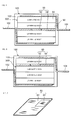
FIG. 1 is a perspective view of a bipolar secondary battery according to this invention, -
FIG. 2 is a longitudinal sectional view of the bipolar secondary battery taken along a line II-II ofFIG. 1 , -
FIG. 3 is a schematic longitudinal sectional view of the bipolar secondary battery, -
FIG. 4 is a perspective view of a current control layer according to this invention, -
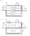
FIG. 5 is a schematic longitudinal sectional view of a bipolar secondary battery showing a variation on the arrangement of the current control layer, -
FIG. 6 is a schematic longitudinal sectional view of a bipolar secondary battery showing another variation on the arrangement of the current control layer, -
FIG. 7 is a perspective view of a current control layer showing a variation on the arrangement of a temperature sensitive resistor according to this invention, -
FIG. 8 is a schematic longitudinal sectional view of a bipolar secondary battery using the current control layer ofFIG. 7 , -
FIG. 9 is a schematic longitudinal sectional view of a bipolar secondary battery according to a second embodiment of this invention, -
FIGS. 10A to 10C are a front view, a rear view and a longitudinal sectional view of a bipolar electrode, -
FIGS. 11A and 11B are a front view and a longitudinal sectional view of the bipolar electrode on which a seal precursor is arranged, -
FIGS. 12A and 12B are a front view and a lateral sectional view of the bipolar electrode on which a separator is laminated, -
FIG. 13 is a schematic side view of a press machine showing a final formation process of a bipolar secondary battery, and -
FIG. 14 is a schematic longitudinal sectional view of a bipolar secondary battery according to aComparative Example # 1 including no current control layer. - Referring to
FIG. 1 of the drawings, a bipolarsecondary battery 100 comprises acase 103 having a substantially rectangular horizontal section and a positive electrodecurrent collecting plate 101 and a negative electrodecurrent collecting plate 102 taken out from the inside of thecase 103 through two opposite sides of thecase 103. - Referring to
FIG. 2 , the bipolarsecondary battery 100 comprises a batterymain body 300 inside thecase 103. The batterymain body 300 is formed by connecting two laminatedbodies 30, in each of which a plurality ofcells 26 is laminated, in series. Thecells 26 are formed of a lithium ion cell, for example. The positive electrode current collectingplate 101 and the negative electrodecurrent collecting plate 102 are fixed to the inner peripheral surface of thecase 103 while gripping the batterymain body 300. - The
case 103 functions to block the batterymain body 300 from outside air and protect the batterymain body 300. Thecase 103 is composed of a pair ofcase members case members main body 300 and a flange portion surrounding the recessed portion. - The
case 103 is integrally formed by welding the flange portions of the pair ofcase members plate 101 and the negative electrodecurrent collecting plate 102 extending from the inside to the outside of thecase 103. Thecase 103 is made of a sheet-like material having such strength as not to damage the laminatedbodies 30 against a pressure difference produced between the inside and the outside of thecase 103 and deformable flexibility. Preferably, the sheet-like material does not allow electrolytic solutions and gases to permeate, has an electrical insulation property and is chemically stable against materials such as electrolytic solutions. - Preferably, a laminated film, polyethylene, polypropylene, polycarbonate and the like are used as the sheet-like material. The laminated film is such that a metal foil of a metal including an alloy of aluminum, stainless steel, nickel, copper or the like is covered with an insulating synthetic resin film such as a polypropylene film.
- The
cell 26 constituting the laminatedbody 30 is composed of anelectrolyte layer 25, a positive electrodeactive material layer 23 and a negative electrodeactive material layer 24 laminated on opposite sides of theelectrolyte layer 25, and plate-likecurrent collectors 22 laminated on the outer sides of the positive electrodeactive material layer 23 and the negative electrodeactive material layer 24 with respect to a lamination direction and having a larger area. However, in the case of laminating the plurality ofcells 26 as shown, only onecurrent collector 22 is provided between theadjacent cells 26. - A known material is used for the
current collector 22. For example, aluminum or stainless steel (SUS) can be used. A polymer material may also be used for thecurrent collector 22. Specifically, polyolefin (polypropylene, polyethylene), polyester (PET, PEN), polyimide, polyamide and polyvinylidene fluoride (PVdF) can be used. To provide these polymer materials with electrical conductivity, particles of carbon such as Ketjen Black, acetylene black or carbon black or of a metal such as aluminum (Al), copper (Cu), stainless steel (SUS) or titanium (Ti) are preferably dispersed in the polymer material. - The positive electrode
active material layer 23 comprises a positive electrode active material and can further comprise a conductive assistant, a binder and the like. A complex oxide of a transition metal and lithium used in a solution lithium-ion battery can be used as the positive electrode active material. - The negative electrode
active material layer 24 comprises a negative electrode active material and can further comprise a conductive assistant, a binder and the like. A negative electrode active material used in a solution lithium-ion battery can be used as the negative electrode active material. - Particularly, it is possible to form a battery with excellent capacity and output characteristic by using a lithium-transition metal complex oxide as the positive electrode active material of the positive electrode
active material layer 23 and using a carbon or lithium-transition metal complex oxide as the negative electrode active material of the negative electrodeactive material layer 24. - The
electrolyte layer 25 is a layer or a liquid electrolyte including an ion-conducting polymer. In this embodiment, a polymer gel electrolyte obtained by impregnating a separator as a base material with a pre-gel solution and then applying chemical crosslinking or physical crosslinking is used as the electrolyte. An electrolytic solution included in theelectrolyte layer 25 contains an organic solvent such as polyprene carbonate, ethylene carbonate or diethyl carbonate, and boils and gasifies with an increase in temperature. The melting point of the separator is 134 degrees Celsius (°C) when a polyethylene (PE) film is used as the separator. The boiling point of the electrolytic solution is 140°C. - Although described in detail later, the electrolytic solution is applied to surfaces of the positive electrode
active material layer 23 and the negative electrodeactive material layer 24 and impregnated into the separator by placing the positive electrodeactive material layer 23 and the negative electrodeactive material layer 24 on the separator. It should be noted that a detailed structure is not shown inFIG. 2 so as to show the configuration of the batterymain body 300 in an easily understandable manner. Specifically, the separator is not shown. - The outer periphery of the
cell 26 is covered by aseal portion 40. Theseal portion 40 is filled between outer peripheral parts of the adjacentcurrent collectors 22 and blocks the contact of the positive electrodeactive material layer 23, theelectrolyte layer 25 and the negative electrodeactive material 24 with outside air. Theseal portion 40 prevents a reduction in the ion-conductivity of the electrolyte by sealing thecell 26. Further, a liquid junction by liquid leakage is prevented in the case of using a liquid or semisolid gel electrolyte. - A rubber-based resin which adheres to the
current collector 22 by being pressed and deformed or a thermally fusible resin which adheres to thecurrent collector 22 by being thermally fused through heating and pressing can be, for example, used as a seal precursor. - The rubber-based resin is not particularly limited, but preferably selected from a group including silicon-based rubber, fluorine-based rubber, olefin-based rubber and nitrile-based rubber. These rubber-based resins are excellent in sealing ability, alkali resistance, chemical resistance, durability, weather resistance, heat resistant, etc. and these excellent properties and qualities can be maintained for a long period of time also in the use environments of secondary batteries.
- The thermally fusible resin preferably exhibits an excellent sealing effect in every use environment of the
laminated body 30. The thermally fusible resin is, for example, selected from a group including silicon, epoxy, urethane, polybutadiene, olefin-based resin (polypropylene, polyethylene, etc.) and paraffin wax. These thermally fusible resins are excellent in sealing ability, alkali resistance, chemical resistance, durability, weather resistance, heat resistance, etc. and excellent properties and qualities can be maintained for a long period of time in the use environments of secondary batteries. - In a production process of the
laminated body 30, a plurality ofbipolar electrodes 21 in each of which the positive electrodeactive material layer 23 is formed on one surface of thecurrent collector 22 and the negative electrodeactive material layer 24 is formed on the other surface and a plurality of electrolyte layers 25 are alternatively laminated over six layers. - A
current collector 22a and acurrent collector 22b are laminated on both ends of thelaminated body 30 with respect to the lamination direction. Different from thecurrent collector 22, the positive electrodeactive material layer 23 is formed on one surface of thecurrent collector 22a, but nothing is formed on the other surface. The negative electrodeactive material layer 24 is formed on one surface of thecurrent collector 22b, but nothing is formed on the other surface. Thecurrent collector 22a is laminated with the positive electrodeactive material layer 23 held in contact with theelectrolyte layer 25. Thecurrent collector 22b is laminated with the negative electrodeactive material layer 24 held in contact with theelectrolyte layer 25. Thecurrent collector 22a forms a positive electrode of thelaminated body 30 and thecurrent collector 22b forms a negative electrode of thelaminated body 30. - Six
cells 26 laminated as described above are thermally pressed using a thermal press machine so that theseal portions 40 have a predetermined thickness, and theuncured seal portions 40 are further cured, whereby the bipolarlaminated body 30 is completed. - Referring to
FIG. 3 , the batterymain body 300 comprises twolaminated bodies 30 arranged in series such that acurrent control layer 50 is arranged between thecurrent collector 22a of onelaminated body 30 and thecurrent collector 22b of the otherlaminated body 30. It should be noted that essential parts are drawn in a deformed manner inFIG. 3 to clearly show characteristics. - Referring to
FIG. 4 , thecurrent control layer 50 comprises a temperaturesensitive resistor 52 whose electrical resistance increases in response to a temperature increase and a current interruptingportion 54 having an electrical resistance value higher than the resistance of the temperaturesensitive resistor 52 when temperature increases. - The current interrupting
portion 54 is formed of a plate member that has an outer shape equivalent to those of the adjacentcurrent collectors portion 54 and the temperaturesensitive resistor 52 is fitted into the cut part. - The temperature
sensitive resistor 52 has a property of increasing the electrical resistance in response to a temperature increase. The current interruptingportion 54 has a higher electrical resistance than the temperaturesensitive resistor 52 when temperature increases. - The area of the temperature
sensitive resistor 52 to be fitted into the central part of the current interruptingportion 54 is set to be smaller than surfaces facing the positive electrodeactive material layer 23 and the negative electrodeactive material layer 24, i.e. an electrical reaction area. Thus, current density of the temperaturesensitive resistor 52 when the bipolarsecondary battery 100 is charged and discharged is higher than current density in thelaminated bodies 30. In terms of the electrical resistance increasing property caused by a temperature increase, the area of the temperaturesensitive resistor 52 is preferably between 1/2 and 1/500 of the electrical reaction area of the positive electrodeactive material layer 23 and the negative electrodeactive material layer 24. - The temperature
sensitive resistor 52 and the current interruptingportion 54 electrically connect the adjacentcurrent collector 22a of onelaminated body 30 and thecurrent collector 22b of the otherlaminated body 30 in parallel. - The current interrupting
portion 54 is made of a resin material which allows almost no current flow, e.g. polyolefin such as polypropylene (PP) or polyethylene (PE), polyester (PET) or the like. - The temperature
sensitive resistor 52 is formed of a positive temperature coefficient (PTC) thermistor whose electrical resistance increases in response to a temperature increase. The temperaturesensitive resistor 52 has a higher glass transition point than other constituent elements of the batterymain body 300 and starts increasing the electrical resistance at a temperature lower than the melting points of the other constituent elements or the boiling point of the electrolytic solution. By this property, the temperaturesensitive resistor 52 can suppress a current flowing in the batterymain body 300 by increasing the electrical resistance before the constituent elements of the batterymain body 300 are damaged due to a temperature increase. - Polymer PTC, inorganic oxide PTC or the like can be used as the material of the PTC thermistor. Alternatively, a material obtained by dispersing a conductive substance in polymer such as polypropylene (PP) or polyethylene (PE), a conductive porous or meshed member or a material obtained by coating a meshed member made of PP polymer or PE polymer with nickel (Ni) metal can be used as the material of the PTC thermistor.
- If the electrical resistance of the temperature
sensitive resistor 52 in a normal temperature condition during the normal use of the bipolarsecondary battery 100 is set to be 1/100 or less of the internal resistance of thelaminated bodies 30, thecurrent control layer 50 does not affect charge/discharge performance of the bipolarsecondary battery 100. - A temperature at which the electrical resistance starts increasing differs depending on the type of the PTC. By deciding which PCT to use, the temperature at which the electrical resistance starts increasing can be arbitrarily set.
- Preferably, the temperature at which the electrical resistance of the temperature
sensitive resistor 52 starts increasing is set to be the lower one of the boiling point of the electrolytic solution and the melting point of the separator. That is, this temperature is set at 134°C or lower. By this setting, currents flowing in thelaminated bodies 30 can be suppressed before the electrolytic solution boils and the separator melts. - More preferably, if the temperature at which the electrical resistance of the temperature
sensitive resistor 52 starts increasing is set at a temperature lower than the lower one of the boiling point of the electrolytic solution and the melting point of the separator by 20°C, the overshoot of a temperature increase can be prevented even in a condition where the temperature increase is accelerated by an excessive current. - As the temperature
sensitive resistor 52, it is also preferable to use a PTC element having such a reversible property with respect to temperature that resistance increases with increasing temperature and decreases with decreasing temperature. The temperaturesensitive resistor 52 formed of such a PTC element suppresses a current by increasing a resistance value when an excessive current flows while allowing a current to flow again by decreasing the resistance value when temperature decreases due to the suppressed current. That is, by repeatedly suppressing a current and lifting the suppression, in other words, by inducing a hunching phenomenon, battery energy can be gradually released. - However, the use of the PTC element having the reversible property is not an essential requirement of this invention. Even if a PTC element having an irreversible property is used as the temperature
sensitive resistor 52, currents flowing in thelaminated bodies 30 can be suppressed before the electrolytic solution boils and the separator melts. - The bipolar
secondary battery 100 is completed by laminating the positive electrodecurrent collecting plate 101 and the negative electrodecurrent collecting plate 102 on the opposite end surfaces of the batterymain body 300 with respect to the lamination direction of thecells 26 and housing and vacuum-sealing them into thecase 103 as described above. - In the bipolar
secondary battery 100 used in an electrically-driven vehicle such as a hybrid electric vehicle (HEV) or an electric vehicle (EV), various electrical circuits that operate on power supplied from the bipolarsecondary battery 100 may experience trouble, for example, when a strong impact is applied to a vehicle body. If a current is supplied from the bipolarsecondary battery 100 to the faulty electrical circuit, an excessive current continues to flow into the faulty electrical circuit to heat the circuit, whereby a high-current line may be shorted. Further, high-current lines in the bipolarsecondary battery 100 may be possibly shorted. - This bipolar
secondary battery 100 comprises the temperaturesensitive resistor 52 having an area smaller than the electrical reaction area of the positive electrodeactive material layer 23 and the negative electrodeactive material layer 24 between thelaminated bodies 30. Inevitably, the density of a current flowing in the temperaturesensitive resistor 52 becomes higher than that in thelaminated bodies 30. Accordingly, if an excessive current flows in the bipolarsecondary battery 100, the self-heat generation of the temperaturesensitive resistor 52 first occurs. Subsequent temperature increases of thelaminated bodies 30 promote a temperature increase of the temperaturesensitive resistor 52 arranged between thelaminated bodies 30. - The temperature
sensitive resistor 52 increases the resistance value with increasing temperature. Accordingly, the flow of a short-circuit current is suppressed by the temperaturesensitive resistor 52 whose resistance value has increased before the temperatures of thelaminated bodies 30 reach an upper limit temperature at which battery functions stop. As a result, an excessive current is suppressed at an early stage and a temperature increase of the batterymain body 300 due to the excessive current can be prevented. - For high responsiveness to an excessive current, the temperature
sensitive resistor 52 desirably has a small area and is made of a material that quickly increases resistance in response to a temperature increase. On the other hand, the electrical resistance of the temperaturesensitive resistor 52 in normal time should be low not to affect normal charge/discharge performance of the bipolarsecondary battery 100. To meet these requirements, the area of the temperaturesensitive resistor 52 is preferably set in the range of 1/2 to 1/100 of the electrical reaction area of the positive electrodeactive material layer 23 and the negative electrodeactive material layer 24. - As shown in
FIGS. 5 to 8 , the arrangement of thecurrent control layer 50 and the position of the temperaturesensitive resistor 52 in thecurrent control layer 50 are not necessarily limited to those in this example. It should be noted that essential parts are drawn in a deformed manner inFIGS. 5, 6 and8 to clearly show characteristics as inFIG. 3 . - Referring to
FIG. 5 , in the case of forming the batterymain body 300 by fourlaminated bodies 30, thecurrent control layer 50 is preferably arranged between the second and thirdlaminated bodies 30 from one end of the batterymain body 300, i.e. in a middle part of the batterymain body 300 with respect to the lamination direction of thelaminated bodies 30. - Referring to
FIG. 6 , in the case of forming the batterymain body 300 by fourlaminated bodies 30, thecurrent control layer 50 can also be arranged between the first and secondlaminated bodies 30 from one end of the batterymain body 300. In this case, the temperaturesensitive resistor 52 is arranged at a position deviated from the center of the batterymain body 300 with respect to the lamination direction of thecells 26 as compared with the bipolarsecondary battery 100 ofFIG. 5 . In such a case, a temperature rise promoting effect of the temperaturesensitive resistor 52 by temperature increases of thelaminated bodies 30 cannot be obtained as much as in the bipolarsecondary battery 100 ofFIG. 5 , but such an arrangement is possible depending on the interior layout of the batterymain body 300. - Referring to
FIGS. 7 and8 , it is also possible to dispose the temperaturesensitive resistor 52 not in the central part of thecurrent control layer 50, but in a corner part of thecurrent control layer 50. If the temperaturesensitive resistor 52 is disposed in the corner part of thecurrent control layer 50, the temperature rise promoting effect of the temperaturesensitive resistor 52 by temperature increases of thelaminated bodies 30 is limited as compared with the case where the temperaturesensitive resistor 52 is disposed in the central part of thecurrent control layer 50, but such an arrangement of the temperaturesensitive resistor 52 is also possible when there is a certain restriction in thecurrent control layer 50. - As described above, according to this bipolar
secondary battery 100, the temperaturesensitive resistor 52 increases the electrical resistance in response to a temperature increase of the bipolarsecondary battery 100 when an excessive current such as a short-circuit current flows in the bipolarsecondary battery 100. This can suppress a temperature increase of the batterymain body 300 by interrupting or suppressing a current. - Particularly, the boiling of the electrolytic solution and the melting of the separator can be prevented by setting the temperature, at which the electrical resistance of the temperature
sensitive resistor 52 starts increasing, to be not higher than the lower one of the boiling point of the electrolytic solution and the melting point of the separator. - Referring to
FIG. 9 , a second embodiment of this invention will be described. Essential parts are drawn in a deformed manner also inFIG. 9 to clearly show characteristics. - In this embodiment, a
current moderation layer 56 having a lower resistance than abipolar electrode 21 is arranged between acurrent control layer 50 and each ofcurrent collectors - The
current moderation layer 56 is formed of a metal foil or a metal plate of aluminum (Al), copper (Cu) or the like. The other configuration of the bipolarsecondary battery 100 is the same as in the first embodiment. - Since the electrical resistance of the
current moderation layer 56 is lower than that of thebipolar electrode 21 in this embodiment, a current from thebipolar electrode 21 can be concentrated on a temperaturesensitive resistor 52 through thecurrent moderation layer 56 even if the resistance of thebipolar electrode 21 is high. Specifically, since thecurrent moderation layer 56 promotes the concentration of a current on the temperaturesensitive resistor 52, the self-heat generation of the temperaturesensitive resistor 52 can be promoted. An effect of promoting the concentration of a current by thecurrent moderation layer 56 becomes more obvious as the resistance of thebipolar electrode 21 increases. - Although it is desirable to provide the current moderation layers 56 on opposite sides of the
current control layer 50, the concentration of a current from onelaminated body 30 can be promoted even if thecurrent moderation layer 56 is provided only on one side of thecurrent control layer 50. - Next, referring to
FIGS. 10A to 10C ,FIGS. 11A and 11B ,FIGS. 12A and 12B ,FIG. 13 and FIG. 14 , an experiment conducted by the inventors on the manufacturing of the bipolarsecondary battery 100 and a current suppression capability of the obtained product will be described. - First, a fabrication process of the
bipolar electrode 21 will be described. - The positive electrode
active material layer 23 was prepared in the following manner. Specifically, a mixture of 85 weight percent (wt%) of LiMn2O4 as a positive electrode active material, 5 weight percent (wt%) of acetylene black as a conductive assistant and 10 wt% of polyvinylidene fluoride (PVdF) as a binder is prepared. N-methylpyrrolidone (NMP) as a slurry viscosity adjusting solvent was added to the mixture until a viscosity optimal for an application operation was reached, whereby a positive electrode slurry was prepared. - The positive electrode
active material layer 23 of 30 µm was then formed by applying the positive electrode slurry to one surface of a SUS foil having a thickness of 20 microns (µm) as thecurrent collector 22 and drying the positive electrode slurry. - The negative electrode
active material layer 24 was prepared in the following manner. Specifically, a mixture of 90 wt% of hard carbon as a negative electrode active material and 10 wt% of PVDF as a binder is prepared. NMP as a slurry viscosity adjusting solvent was added to the mixture until a viscosity optimal for an application operation was reached, whereby a negative electrode slurry was prepared. - The negative electrode
active material layer 24 of 30 µm was then formed by applying the negative electrode slurry to a surface of thecurrent collector 22 opposite to the positive electrodeactive material layer 23 and drying the negative electrode slurry. - A structure of the
bipolar electrode 21 was thus obtained by forming the positive electrodeactive material layer 23 and the negative electrodeactive material layer 24 on the opposite surfaces of the SUS foil as thecurrent collector 22. - Referring to
FIGS. 10A to 10C , thebipolar electrode 21 was cut into a piece of 160 × 130 millimeters (mm), and the surfaces of the SUS were exposed by peeling off an outer peripheral part having a width of 10 mm from each of the positive and negative electrodes. As a result, thebipolar electrode 21 was prepared which includes electrode surfaces of 140 × 110 mm and thecurrent collector 22 formed of the SUS having a width of 10 mm exposed at the outer peripheral sides of the electrode surfaces. - Next, a formation process of the
electrolyte layer 25 will be described. - A pre-gel electrolyte containing 90 wt% of an electrolytic solution containing 1 moll of lithium hexafluorophosphate (LiPF6) and having a boiling point of 242°C and 10 wt% of PVdF-HFP containing 10 wt% of a hexafluoropropene (HFP) copolymer as a host polymer in a mixed solvent of propylene carbonate-ethylene carbonate (PC-EC) was prepared. By adding dimethyl carbonate (DMC) as a viscosity adjusting solvent to this pre-gel electrolyte until a viscosity optimal for an application operation was reached, an electrolytic solution was prepared. The electrolytic solution was applied to each electrode surface of the positive electrode
active material layer 23 and the negative electrodeactive material layer 24 of thebipolar electrode 21 and DMC was dried. - By alternately placing this
bipolar electrode 21 and the separator SP as shown inFIGS. 12A and 12B , the electrolytic solution applied to each electrode surface of the positive electrodeactive material layer 23 and the negative electrodeactive material layer 24 was impregnated into the separator SP. In this way, theelectrolyte layer 25 was formed in an area range of the separator SP corresponding to each electrode surface of the positive electrodeactive material layer 23 and the negative electrodeactive material layer 24. - Next, a formation process of a seal precursor will be described.
- Referring to
FIGS. 11A and 11B , aseal precursor 40A made of a one-part uncured epoxy resin was applied to the exposed part of the SUS foil outside the positive electrode of thebipolar electrode 21 using a dispenser. - Referring to
FIGS. 12A and 12B , the separator SP of 170×140 (mm) made of a polyethylene (PE) film having a thickness of 12 µm and a melting point of 134°C was so arranged on the positive electrode side as to cover the entire surface of thecurrent collector 22 including the SUS. In only Example #8 to be described later, a polyimide (PI) separator having a thickness of 15 µm and a melting point of 350°C or higher was used. Thereafter, aseal precursor 40A made of the one-part uncured epoxy resin was applied to a position of the separator SP to be overlapped with theseal precursor 40A using the dispenser. - Herein, the separator SP projects outward through the
seal precursor 40A over the entire circumference as shown. This projecting part touches neither the positive electrodeactive material layer 23 nor the negative electrodeactive material layer 24 and theelectrolyte layer 25 is not formed in this part. Theelectrolyte layer 25 is formed only in an area enclosed by theseal precursors 40A. - By laminating 13 pairs of the
bipolar electrode 21 and the separator SP described above, a structure of thelaminated body 30 in which 12cells 26 are laminated was prepared. - Next, the press molding of a bipolar battery will be described.
- Referring to
FIG. 13 , theseal precursors 40A were cured to obtainseal portions 40 by thermally pressing the structures of thelaminated bodies 30 configured as described above, gripping thecurrent control layer 50 therebetween, with a surface pressure of 1 kilogram (kg) / square centimeter (cm2) (≅ kilopascal (kPa)) at 80°C for 1 hour by a thermal press machine. By this process, theseal portions 40 can be pressed to a predetermined thickness and can be further cured, and thelaminated body 30 in which 12 layers ofcells 26 were laminated was completed. - Next, a fabrication process of the
current control layer 50 will be described. - A PET plate having a thickness of 300 µm was cut into a piece of 170 mm × 140 mm similarly to the separator SP. A cut of a size into which the temperature
sensitive resistor 52 was fitted was provided at a position of the cut PET plate corresponding to the central part shown inFIG. 4 . In only a PET plate for Example #13 to be described later, a cut of a size into which the temperaturesensitive resistor 52 was fitted was provided at a position corresponding to a corner part of thecurrent control layer 50 as shown inFIG. 7 . - Pieces of different polymer PTC sheets, whose resistance starts suddenly increasing at 140°C, 120°C and 110°C, cut out to have a predetermined area were used as the temperature
sensitive resistor 52. - The current moderation layers 56 used in Example #10 to be described later were prepared by cutting an aluminum (Al) plate of 50 µm into a piece of 160 × 130 (mm). The prepared two current moderation layers 56 were arranged to sandwich the
current control layer 50 from opposite sides. - Next, packaging will be described.
- The battery
main body 300 was obtained by gripping thecurrent control layer 50 between twolaminated bodies 30 or any two oflaminated bodies 30 out of fourlaminated bodies 30 formed in the above process via conductive double-sided adhesive tapes. For Example #10, two current moderation layers 56 were fixed to the both surfaces of thecurrent control layer 50 via conductive double-sided adhesive tapes and this was arranged between twolaminated bodies 30 via conductive double-sided adhesive tapes to obtain the batterymain body 300 of each ofExamples # 1 to #13. - On the other hand, for
Comparative Example # 1, twolaminated bodies 30 were directly bonded using a conductive double-sided adhesive tape to obtain the batterymain body 300. - Further, the positive electrode
current collecting plate 101 and the negative electrodecurrent collecting plate 102 were bonded to both ends of the batterymain body 300 using conductive double-sided adhesive tapes. A surface of the positive electrodecurrent collecting plate 101 opposite to the batterymain body 300 was bonded to the inner peripheral surface of thecase member 103a using a double-sided adhesive tape. The flange portions of thecase members case 103 with taken-out parts of the positive electrodecurrent collecting plate 101 and the negative electrodecurrent collecting plate 102 gripped between the flange portions. - By the above process,
Examples # 1 to #13 according to this invention relating to the bipolarsecondary battery 100 andComparative Example # 1 not according to this invention were completed. - Specifications of
Examples # 1 to #13 andComparative Example # 1 are shown in TABLE-1. -
TABLE-1 NAME CURRENT CONTROL LAYER NOS. OF LAMINATED BODIES TEMPERATURE SENSITIVE RESISTOR AREA/ ELECTRICAL REACTION AREA LAMINATED BODY RESISTANCE/ TEMPERATURE SENSITIVE RESISTOR RESISTANCE IN NORMAL STATE. SEPARATOR MATERIAL RESISTANCE INCREASE START TEMPERATURE OF TEMPERATURE SENSITIVE RESISTOR BATTERY SHAPE Comparative Example#1 Absent 2 - - PE - FIG. 14 Example#1 Present 2 2/3 1/100 or less PE 140°C FIG. 3 Example#2 Present 2 1/2 1/100 or less PE 140°C FIG. 3 Example#3 Present 2 1 /5 1/100 or less PE 140°C FIG. 3 Example#4 Present 2 1/50 1/100 or less PE 140°C FIG. 3 Example#5 Present 2 1/100 1/100 or less PE 140°C FIG. 3 Example#6 Present 2 1/500 Approx. 3/100 PE 140°C FIG. 3 Example#7 Present 2 1/100 1/100 or less PE 120°C FIG. 3 Example#8 Present 2 1/100 1/100 or less PI 140°C FIG. 3 Example#9 Present 2 1/100 1/100 or less PE 110°C FIG. 3 Example#10 Present 2 1/100 1/100 or less PE 120°C FIG. 9 Example#1 Present 4 1/100 1/100 or less PE 120°C FIG. 5 Example#12 Present 4 1/100 1/100 or less PE 120°C FIG. 6 Example#13 Present 4 1/100 1/100 or less PE 120°C FIG. 8 - In
Examples # 1 to #10, the batterymain body 300 was composed of twolaminated bodies 30, thecurrent control layer 50 was arranged between the twolaminated bodies 30 and the temperaturesensitive resistor 52 was arranged in the central part of thecurrent control layer 50. - In
Example # 1, the area of the temperaturesensitive resistor 52 having a resistance increase starting temperature of 140°C was set at 2/3 of the electrical reaction area of the positive electrodeactive material layer 23 and the negative electrodeactive material layer 24. - In Example #2, the area of the temperature
sensitive resistor 52 having a resistance increase starting temperature of 140°C was set at 1/2 of the electrical reaction area of the positive electrodeactive material layer 23 and the negative electrodeactive material layer 24. - In Example #3, the area of the temperature
sensitive resistor 52 having a resistance increase starting temperature of 140°C was set at 1/5 of the electrical reaction area of the positive electrodeactive material layer 23 and the negative electrodeactive material layer 24. - In Example #4, the area of the temperature
sensitive resistor 52 having a resistance increase starting temperature of 140°C was set at 1/50 of the electrical reaction area of the positive electrodeactive material layer 23 and the negative electrodeactive material layer 24. - In Example #5, the area of the temperature
sensitive resistor 52 having a resistance increase starting temperature of 140°C was set at 1/100 of the electrical reaction area of the positive electrodeactive material layer 23 and the negative electrodeactive material layer 24. - In Example #6, the area of the temperature
sensitive resistor 52 having a resistance increase starting temperature of 140°C was set at 1/500 of the electrical reaction area of the positive electrodeactive material layer 23 and the negative electrodeactive material layer 24. A resistance value of the temperaturesensitive resistor 52 of the bipolarsecondary battery 100 in normal use was approximately 3/100 of the internal resistance of thelaminated body 30. - In Example #7, the area of the temperature
sensitive resistor 52 having a resistance increase starting temperature of 120°C was set at 1/100 of the electrical reaction area of the positive electrodeactive material layer 23 and the negative electrodeactive material layer 24. - In Example #8, the area of the temperature
sensitive resistor 52 having a resistance increase starting temperature of 140°C was set at 1/100 of the electrical reaction area of the positive electrodeactive material layer 23 and the negative electrodeactive material layer 24 of thelaminated body 30 as in Example #5. Further, a polyimide (PI) separator having a thickness of 15 µm and a melting point of 350°C or higher as described above was used as the separator SP. The separator SP in other Examples andComparative Example # 1 was made of polyethylene (PE) having a melting point of 134°C. - In Example #9, the temperature
sensitive resistor 52 having a resistance increase starting temperature of 110°C was used and the area thereof was set at 1/100 of the electrical reaction area of the positive electrodeactive material layer 23 and the negative electrodeactive material layer 24. - In Example #10, the current moderation layers 56 formed in the process described above were arranged between the
current control layer 50 and thelaminated bodies 30 on the opposite sides thereof as shown inFIG. 9 . - In Examples #11 to #13, the battery
main body 300 was composed of fourlaminated bodies 30. - In Example #11, the area of the temperature
sensitive resistor 52 having a resistance increase starting temperature of 120°C was set at 1/100 of the electrical reaction area of the positive electrodeactive material layer 23 and the negative electrodeactive material layer 24. Further, as shown inFIG. 5 , thecurrent control layer 50 was arranged between the second and thirdlaminated bodies 30 from one end of the batterymain body 300, i.e. in a middle part of the batterymain body 300 with respect to the lamination direction of thelaminated bodies 30. - In Example #12, the temperature
sensitive resistor 52 having a resistance increase starting temperature of 120°C was used and the area thereof was set at 1/100 of the electrical reaction area of the positive electrodeactive material layer 23 and the negative electrodeactive material layer 24. Further, as shown inFIG. 6 , thecurrent control layer 50 was arranged between the first and secondlaminated bodies 30 from one end of the batterymain body 300 with respect to the lamination direction of thelaminated bodies 30, i.e. at a position deviated from the middle part of the batterymain body 300. - In Example #13, the temperature
sensitive resistor 52 having a resistance increase starting temperature of 120° was used and the area thereof was set at 1/100 of the electrical reaction area of the positive electrodeactive material layer 23 and the negative electrodeactive material layer 24. Further, thecurrent control layer 50 was arranged between the second and thirdlaminated bodies 30 from one end of the batterymain body 300 with respect to the lamination direction of thelaminated bodies 30, i.e. in the middle part of the batterymain body 300. As shown inFIGS. 7 and8 , the temperaturesensitive resistor 52 was arranged in a corner part of thecurrent control layer 50. - It should be noted that the boiling point of the electrolytic solution was 140°C in all of
Comparative Example # 1 andExamples # 1 to #13. - A short-circuit test of an external electrical circuit connected to the bipolar
secondary batteries 100 ofComparative Example # 1 andExamples # 1 to #13 was conducted to measure a reached maximum temperature and a maximum temperature arrival time of the batterymain body 300 and battery states after the test were confirmed. Test results are shown in TABLE-2A and TABLE-2B. -
TABLE-2A ITEM Comparative Example# 1Example# 1Example#2 Example#3 Example#4 Example#5 Example#6 Max. Temp. 300°C 250°C 220°C 215°C 210°C 200°C 200°C Max. Arrival Time 0.5min. 3min. 15min. 18min. 20min. 30min. 60min. Final State Battery Swelling (Large) Battery Swelling (Large) Battery Swelling (Medium) Battery Swelling (Medium) Battery Swelling (Small) Battery Swelling (Small) Battery Swelling (Small) TABLE-2B ITEM Example#7 Example#8 Example#9 Example#10 Example#11 Example#12 Example#13 Max. Temp. 130°C 140°C 115°C 120°C 120°C 120°C 120°C Max. Arrival Time 30min. 30min. 60min. 90min. 30min. 20min. 20min. Final State No Change No Change No Change No Change No Change No Change No Change - Comparison of
Examples # 1 to #6 reveals that the reached maximum temperature of the batterymain body 300 decreases and the maximum temperature arrival time becomes longer as the area of the temperaturesensitive resistor 52 is reduced. Particularly, if the ratio of the area of the temperaturesensitive resistor 52 to the electrical reaction area of the positive electrodeactive material layer 23 and the negative electrodeactive material layer 24 is set at 1/2 or less, the reached maximum temperature of the batterymain body 300 is further reduced and the maximum temperature arrival time is drastically extended. - However, if the area ratio of the temperature
sensitive resistor 52 is made excessively small as in Example #6, a ratio of the resistance of thecurrent control layer 50 to the internal resistance of thelaminated body 30 becomes as high as 3/100 and an output of thelaminated body 30 in a normal operation is affected. Thus, the resistance of thecurrent control layer 50 to the internal resistance of thelaminated body 30 is preferably set at 1/100 or more. - In any of
Examples # 1 to #6, the resistance increase starting temperature of the temperaturesensitive resistor 52 is 140°C, which is equal to the boiling point of 140°C of the electrolytic solution and above the melting point of 134°C of the separator SP. Thus, a current suppression effect can be obtained, but the reached maximum temperature is 215°C to 250°C which exceed the melting point of the separator SP and the boiling point of the electrolytic solution. Thus, the melting of the separator SP and the boiling of the electrolytic solution cannot be completely prevented. As a result, the batterymain body 300 undergoes a certain expansion deformation. - On the other hand, in Example #7, the resistance increase starting temperature of 120°C of the temperature
sensitive resistor 52 satisfies the condition of being not higher than the lower one of the boiling point of 140°C of the electrolytic solution and the melting point of 134°C of the separator SP. Similarly, in Example #8, the resistance increase starting temperature of 140°C of the temperaturesensitive resistor 52 also satisfies the condition of being not higher than the lower one of the boiling point of 140°C of the electrolytic solution and the melting point of 350°C of the separator SP. In Examples #7 and #8, the reached maximum temperature could be suppressed to or below the boiling point of 140°C of the electrolytic solution and the deformation of the batterymain body 300 could be prevented. - In Example #9, since the resistance increase starting temperature of the temperature
sensitive resistor 52 was even lower, the reached maximum temperature was only 115°C that was lower than both the boiling point of 140°C of the electrolytic solution and the melting point of 120°C of the separator SP and the boiling of the electrolytic solution and the melting of the separator SP could be more reliably prevented. - In Example #10, since the current moderation layers 56 were arranged on the opposite sides of the
current control layer 50 in addition to the configuration of Example #7, the current is concentrated on the temperaturesensitive resistor 52 to an increased degree and the reached maximum temperature could be lower than in Example #7 and the maximum temperature arrival time could be extended more than in Example #7. The current moderation layers 56 are thought to have a large effect as the resistance of thebipolar electrode 21 composed of thecurrent corrector 22, the positive electrodeactive material layer 23 and the negative electrodeactive material layer 24 increases. - It was found from comparison of Examples #11 and #12 that the time to reach the maximum temperature was more extended when the
current control layer 50 was arranged near the middle point of the batterymain body 300 with respect to the lamination direction of thelaminated bodies 30 than when it was arranged at another position. This is thought to be because the transfer of heat generated in the batterymain body 300 to thecurrent control layer 50 is faster at a position near the middle point of the batterymain body 300 than at a position distant from the middle point. - It was found from comparison of Examples #11 and #13 that the time to reach the maximum temperature was more extended when the temperature
sensitive resistor 52 was arranged in the central part of thecurrent control layer 50 than when it was arranged in the corner part. This is thought to be because the transfer of heat generated in the batterymain body 300 to thecurrent control layer 50 is faster in the central part of thecurrent control layer 50 than in the corner part. - The contents of
Tokugan 2010-115123 - Although the invention has been described above with reference to certain embodiments, the invention is not limited to the embodiments described above. Modifications and variations of the embodiments described above will occur to those skilled in the art, within the scope of the claims.
- For example, this invention is applicable not only to lithium-ion batteries, but also to any bipolar secondary battery.
- As described above, the flow of a large amount of current into a bipolar secondary battery can be interrupted according to this invention. This produces a preferable effect in protecting a secondary battery of an electric vehicle.
- The embodiments of this invention in which an exclusive property or privilege is claimed are defined as follows:
Claims (11)
- A bipolar secondary battery (100), comprising:a plurality of laminated bodies (30) connected in series, each laminated body (30) comprising a plurality of bipolar electrodes (21) laminated via an electrolyte layer and each bipolar electrode (21) comprising:a plate-like current collector (22);a positive electrode active material layer (23) arranged on one surface of the current collector (22); anda negative electrode active material layer (24) arranged on another surface of the current collector (22);a positive electrode (22a) formed on one end of the plurality of laminated bipolar electrodes (21) in a lamination direction;a negative electrode (22b) formed on another end of the plurality of laminated bipolar electrodes (21) in the lamination direction; anda temperature sensitive resistor (52) arranged between the positive electrode (22a) and the negative electrode (22b) of a pair of adjacent laminated bodies (30), the temperature sensitive resistor (52) increasing resistance in response to a temperature increase and having a smaller area than an electrical reaction area of the positive electrode active material layer (23) and the negative electrode active material layer (24).
- The bipolar secondary battery (100) as defined in Claim 1, further comprising a current interrupting portion (54) provided on the same plane as the temperature sensitive resistor (52) so as to form a current control layer (50) arranged between the pair of the adjacent laminated bodies (30), wherein the current interrupting portion (54) has a higher electrical resistance than the temperature sensitive resistor (52),
- The bipolar secondary battery as defined in Claim 1 or Claim 2, wherein the electrolyte layer (25) is formed of a separator (SP) infiltrated with an electrolytic solution.
- The bipolar secondary battery as defined in Claim 3, wherein a resistance increase starting temperature at which the temperature sensitive resistor (52) starts increasing the electrical resistance is lower than the lower one of a boiling point of the electrolytic solution and a melting point of the separator (SP).
- The bipolar secondary battery as defined in Claim 3 or Claim 4, further comprising a current moderation layer (56) arranged between each of the pair of laminated bodies (30) and the temperature sensitive resistor (52), wherein the current moderation layer (56) has a lower electrical resistance than any one of the current collector (22), the positive electrode active material layer (23) and the negative electrode active material layer (24).
- The bipolar secondary battery as defined in any one of Claim 1 through Claim 5, wherein a resistance increase starting temperature at which the temperature sensitive resistor (52) starts increasing the electrical resistance is within a range of 120 to 140 degrees Celsius.
- The bipolar secondary battery as defined in any one of Claim 1 through Claim 5, wherein a resistance value of the temperature sensitive resistor (52) in a normal charge/discharge operation of the bipolar secondary battery (100) is within a range of 1 / 2 to 1/100 of the electrical resistance of the laminated body (30).
- The bipolar secondary battery as defined in any one of Claim 1 through Claim 7, wherein the temperature sensitive resistor (52) is formed of a positive temperature coefficient thermistor whose electrical resistance reversibly changes with temperature:
- The bipolar secondary battery as defined in any one of Claim 1 through Claim 8, wherein the bipolar secondary battery comprises three or more laminated bodies (30) connected in series.
- The bipolar secondary battery (100) as defined in any one of Claim 1 through Claim 9, wherein the temperature sensitive resistor (52) is in contact with a central part of the current collector (22).
- The bipolar secondary battery (100) as defined in any one of Claim 1 through Claim 10, wherein the bipolar secondary battery (100)comprises an even number of laminated bodies (30) connected in series, and the temperature sensitive resistor (52) is arranged at a middle position of the even number of laminated bodies (30) connected in series with respect to a connecting direction of the laminated bodies (30).
Applications Claiming Priority (2)
| Application Number | Priority Date | Filing Date | Title |
|---|---|---|---|
| JP2010115123 | 2010-05-19 | ||
| PCT/JP2011/061301 WO2011145609A1 (en) | 2010-05-19 | 2011-05-17 | Bipolar secondary battery |
Publications (3)
| Publication Number | Publication Date |
|---|---|
| EP2573839A1 true EP2573839A1 (en) | 2013-03-27 |
| EP2573839A4 EP2573839A4 (en) | 2017-01-11 |
| EP2573839B1 EP2573839B1 (en) | 2017-09-13 |
Family
ID=44991711
Family Applications (1)
| Application Number | Title | Priority Date | Filing Date |
|---|---|---|---|
| EP11783543.9A Active EP2573839B1 (en) | 2010-05-19 | 2011-05-17 | Bipolar secondary battery |
Country Status (5)
| Country | Link |
|---|---|
| US (1) | US8900734B2 (en) |
| EP (1) | EP2573839B1 (en) |
| JP (1) | JP5477467B2 (en) |
| CN (1) | CN102884655B (en) |
| WO (1) | WO2011145609A1 (en) |
Cited By (1)
| Publication number | Priority date | Publication date | Assignee | Title |
|---|---|---|---|---|
| EP3386006A1 (en) * | 2017-04-07 | 2018-10-10 | Toyota Jidosha Kabushiki Kaisha | Stacked battery |
Families Citing this family (12)
| Publication number | Priority date | Publication date | Assignee | Title |
|---|---|---|---|---|
| JP6305126B2 (en) * | 2014-03-12 | 2018-04-04 | マクセルホールディングス株式会社 | Battery pack with preliminary charge / discharge function |
| US9720299B1 (en) * | 2015-01-12 | 2017-08-01 | Kinestral Technologies, Inc. | Electrochromic multi-layer devices with cross-linked ion conducting polymer |
| KR102065733B1 (en) * | 2015-10-21 | 2020-01-13 | 주식회사 엘지화학 | Electrode composite, secondary battery and cable type secondary battery including the same |
| WO2017149990A1 (en) * | 2016-02-29 | 2017-09-08 | パナソニックIpマネジメント株式会社 | Stacked nonaqueous electrolyte secondary battery |
| EP3591741B1 (en) * | 2017-03-03 | 2021-01-13 | Nissan Motor Co., Ltd. | Secondary battery and secondary battery control method |
| CN107895761A (en) * | 2017-11-13 | 2018-04-10 | 桑顿新能源科技有限公司 | A kind of metal casing lithium ion battery cover plate |
| JP6915567B2 (en) * | 2018-02-28 | 2021-08-04 | 株式会社豊田自動織機 | Power storage module |
| JP6939685B2 (en) * | 2018-04-12 | 2021-09-22 | トヨタ自動車株式会社 | Laminated battery |
| CN110120545B (en) * | 2019-05-13 | 2021-05-07 | 浙江锋锂新能源科技有限公司 | Non-contact mixed solid-liquid electrolyte lithium storage battery and preparation method thereof |
| KR102917756B1 (en) | 2019-12-16 | 2026-01-26 | 다이슨 테크놀러지 리미티드 | Battery cells with internal swelling relief and external cooling functions |
| KR102955692B1 (en) * | 2020-09-29 | 2026-04-22 | 에스케이온 주식회사 | Terminal Protection Cover and Battery Module Including the Same |
| EP4460863A1 (en) * | 2022-01-07 | 2024-11-13 | ROSCHER, Michael | Bipolar battery stack and method for producing same |
Family Cites Families (11)
| Publication number | Priority date | Publication date | Assignee | Title |
|---|---|---|---|---|
| JPH07220755A (en) | 1994-02-07 | 1995-08-18 | Tdk Corp | Layer built lithium secondary battery |
| CN1178328C (en) | 1999-05-17 | 2004-12-01 | 松下电器产业株式会社 | Protection circuit and protection element for secondary battery |
| JP2004178914A (en) * | 2002-11-26 | 2004-06-24 | Nissan Motor Co Ltd | Bipolar electrode and bipolar secondary battery using the electrode |
| JP4472259B2 (en) * | 2002-12-27 | 2010-06-02 | パナソニック株式会社 | Electrochemical element |
| JP2004355953A (en) * | 2003-05-29 | 2004-12-16 | Nissan Motor Co Ltd | Bipolar secondary battery and bipolar secondary battery capacity adjustment system |
| JP2005317468A (en) * | 2004-04-30 | 2005-11-10 | Nissan Motor Co Ltd | Bipolar electrode, bipolar electrode manufacturing method, bipolar battery, battery pack, and vehicle equipped with the same |
| JP5010250B2 (en) * | 2005-11-28 | 2012-08-29 | Necエナジーデバイス株式会社 | Battery stack and battery pack |
| JP5205713B2 (en) * | 2006-05-01 | 2013-06-05 | 日産自動車株式会社 | Bipolar secondary battery |
| JP5104492B2 (en) | 2008-04-07 | 2012-12-19 | トヨタ自動車株式会社 | Solid battery |
| US20100084161A1 (en) * | 2008-10-08 | 2010-04-08 | Robert A. Neal | Conductive film and process for making same |
| JP5341050B2 (en) | 2010-11-08 | 2013-11-13 | オリンパス株式会社 | Printer device and image forming method of printer device |
-
2011
- 2011-05-17 CN CN201180022462.8A patent/CN102884655B/en active Active
- 2011-05-17 WO PCT/JP2011/061301 patent/WO2011145609A1/en not_active Ceased
- 2011-05-17 US US13/698,394 patent/US8900734B2/en active Active
- 2011-05-17 EP EP11783543.9A patent/EP2573839B1/en active Active
- 2011-05-17 JP JP2012515890A patent/JP5477467B2/en active Active
Cited By (2)
| Publication number | Priority date | Publication date | Assignee | Title |
|---|---|---|---|---|
| EP3386006A1 (en) * | 2017-04-07 | 2018-10-10 | Toyota Jidosha Kabushiki Kaisha | Stacked battery |
| US10665850B2 (en) | 2017-04-07 | 2020-05-26 | Toyota Jidosha Kabushiki Kaisha | Stacked battery |
Also Published As
| Publication number | Publication date |
|---|---|
| US8900734B2 (en) | 2014-12-02 |
| JP5477467B2 (en) | 2014-04-23 |
| CN102884655A (en) | 2013-01-16 |
| WO2011145609A1 (en) | 2011-11-24 |
| EP2573839A4 (en) | 2017-01-11 |
| JPWO2011145609A1 (en) | 2013-07-22 |
| CN102884655B (en) | 2015-01-21 |
| EP2573839B1 (en) | 2017-09-13 |
| US20130065097A1 (en) | 2013-03-14 |
Similar Documents
| Publication | Publication Date | Title |
|---|---|---|
| EP2573839B1 (en) | Bipolar secondary battery | |
| EP2573856B1 (en) | Bipolar secondary battery | |
| US20230076651A1 (en) | Current collector for a stacked battery design | |
| JP4661020B2 (en) | Bipolar lithium ion secondary battery | |
| KR20080103847A (en) | Electrode assembly and secondary battery using same | |
| TW201304248A (en) | Group battery | |
| JP2000030742A (en) | Lithium-ion secondary battery element | |
| JP2011048932A (en) | Bipolar secondary battery | |
| WO1999034469A1 (en) | Lithium ion secondary battery | |
| JPWO1999034469A1 (en) | Lithium-ion secondary battery | |
| KR20140013177A (en) | Secondary battery and electrochemical cell having the same | |
| EP3944404A1 (en) | Secondary battery pouch | |
| KR20000066876A (en) | lithum secondary battery | |
| CN112670597B (en) | Electrode assembly, electrochemical device and electronic equipment | |
| KR100475989B1 (en) | Lithium ion secondary battery | |
| CN114583291B (en) | Thermal response safety unit and single battery for battery cell matching | |
| JP7768244B2 (en) | secondary battery | |
| JPH11265704A (en) | Nonaqueous battery and electrode terminal | |
| JP6519998B2 (en) | Electrical device | |
| JP7585760B2 (en) | Power storage device | |
| KR101458259B1 (en) | Pouch type secondary battery and method for manufacturing the same | |
| KR100452116B1 (en) | Lithium ion secondary battery | |
| KR20250071828A (en) | Battery and battery manufacturing method | |
| JP2014032790A (en) | Thin battery | |
| JPWO1999067836A1 (en) | Electrode, method for manufacturing the electrode, and battery using the electrode |
Legal Events
| Date | Code | Title | Description |
|---|---|---|---|
| PUAI | Public reference made under article 153(3) epc to a published international application that has entered the european phase |
Free format text: ORIGINAL CODE: 0009012 |
|
| 17P | Request for examination filed |
Effective date: 20121030 |
|
| AK | Designated contracting states |
Kind code of ref document: A1 Designated state(s): AL AT BE BG CH CY CZ DE DK EE ES FI FR GB GR HR HU IE IS IT LI LT LU LV MC MK MT NL NO PL PT RO RS SE SI SK SM TR |
|
| DAX | Request for extension of the european patent (deleted) | ||
| RA4 | Supplementary search report drawn up and despatched (corrected) |
Effective date: 20161212 |
|
| RIC1 | Information provided on ipc code assigned before grant |
Ipc: H01M 10/0525 20100101ALI20161206BHEP Ipc: H01M 10/04 20060101ALI20161206BHEP Ipc: H01M 2/34 20060101AFI20161206BHEP Ipc: H01M 10/0585 20100101ALI20161206BHEP |
|
| GRAP | Despatch of communication of intention to grant a patent |
Free format text: ORIGINAL CODE: EPIDOSNIGR1 |
|
| INTG | Intention to grant announced |
Effective date: 20170509 |
|
| RIN1 | Information on inventor provided before grant (corrected) |
Inventor name: KAMIMURA, HIROTATSU Inventor name: HOSAKA, KENJI Inventor name: NAKAMURA, YASUTAKA Inventor name: INOUE, SHIHO Inventor name: MINEGISHI, EIJI |
|
| GRAS | Grant fee paid |
Free format text: ORIGINAL CODE: EPIDOSNIGR3 |
|
| GRAA | (expected) grant |
Free format text: ORIGINAL CODE: 0009210 |
|
| AK | Designated contracting states |
Kind code of ref document: B1 Designated state(s): AL AT BE BG CH CY CZ DE DK EE ES FI FR GB GR HR HU IE IS IT LI LT LU LV MC MK MT NL NO PL PT RO RS SE SI SK SM TR |
|
| REG | Reference to a national code |
Ref country code: GB Ref legal event code: FG4D |
|
| REG | Reference to a national code |
Ref country code: CH Ref legal event code: EP |
|
| REG | Reference to a national code |
Ref country code: IE Ref legal event code: FG4D |
|
| REG | Reference to a national code |
Ref country code: AT Ref legal event code: REF Ref document number: 928955 Country of ref document: AT Kind code of ref document: T Effective date: 20171015 |
|
| REG | Reference to a national code |
Ref country code: DE Ref legal event code: R096 Ref document number: 602011041588 Country of ref document: DE |
|
| REG | Reference to a national code |
Ref country code: NL Ref legal event code: MP Effective date: 20170913 |
|
| REG | Reference to a national code |
Ref country code: LT Ref legal event code: MG4D |
|
| PG25 | Lapsed in a contracting state [announced via postgrant information from national office to epo] |
Ref country code: HR Free format text: LAPSE BECAUSE OF FAILURE TO SUBMIT A TRANSLATION OF THE DESCRIPTION OR TO PAY THE FEE WITHIN THE PRESCRIBED TIME-LIMIT Effective date: 20170913 Ref country code: SE Free format text: LAPSE BECAUSE OF FAILURE TO SUBMIT A TRANSLATION OF THE DESCRIPTION OR TO PAY THE FEE WITHIN THE PRESCRIBED TIME-LIMIT Effective date: 20170913 Ref country code: LT Free format text: LAPSE BECAUSE OF FAILURE TO SUBMIT A TRANSLATION OF THE DESCRIPTION OR TO PAY THE FEE WITHIN THE PRESCRIBED TIME-LIMIT Effective date: 20170913 Ref country code: FI Free format text: LAPSE BECAUSE OF FAILURE TO SUBMIT A TRANSLATION OF THE DESCRIPTION OR TO PAY THE FEE WITHIN THE PRESCRIBED TIME-LIMIT Effective date: 20170913 Ref country code: NO Free format text: LAPSE BECAUSE OF FAILURE TO SUBMIT A TRANSLATION OF THE DESCRIPTION OR TO PAY THE FEE WITHIN THE PRESCRIBED TIME-LIMIT Effective date: 20171213 |
|
| REG | Reference to a national code |
Ref country code: AT Ref legal event code: MK05 Ref document number: 928955 Country of ref document: AT Kind code of ref document: T Effective date: 20170913 |
|
| PG25 | Lapsed in a contracting state [announced via postgrant information from national office to epo] |
Ref country code: BG Free format text: LAPSE BECAUSE OF FAILURE TO SUBMIT A TRANSLATION OF THE DESCRIPTION OR TO PAY THE FEE WITHIN THE PRESCRIBED TIME-LIMIT Effective date: 20171213 Ref country code: RS Free format text: LAPSE BECAUSE OF FAILURE TO SUBMIT A TRANSLATION OF THE DESCRIPTION OR TO PAY THE FEE WITHIN THE PRESCRIBED TIME-LIMIT Effective date: 20170913 Ref country code: ES Free format text: LAPSE BECAUSE OF FAILURE TO SUBMIT A TRANSLATION OF THE DESCRIPTION OR TO PAY THE FEE WITHIN THE PRESCRIBED TIME-LIMIT Effective date: 20170913 Ref country code: LV Free format text: LAPSE BECAUSE OF FAILURE TO SUBMIT A TRANSLATION OF THE DESCRIPTION OR TO PAY THE FEE WITHIN THE PRESCRIBED TIME-LIMIT Effective date: 20170913 Ref country code: GR Free format text: LAPSE BECAUSE OF FAILURE TO SUBMIT A TRANSLATION OF THE DESCRIPTION OR TO PAY THE FEE WITHIN THE PRESCRIBED TIME-LIMIT Effective date: 20171214 |
|
| PG25 | Lapsed in a contracting state [announced via postgrant information from national office to epo] |
Ref country code: NL Free format text: LAPSE BECAUSE OF FAILURE TO SUBMIT A TRANSLATION OF THE DESCRIPTION OR TO PAY THE FEE WITHIN THE PRESCRIBED TIME-LIMIT Effective date: 20170913 |
|
| REG | Reference to a national code |
Ref country code: FR Ref legal event code: PLFP Year of fee payment: 8 |
|
| PG25 | Lapsed in a contracting state [announced via postgrant information from national office to epo] |
Ref country code: PL Free format text: LAPSE BECAUSE OF FAILURE TO SUBMIT A TRANSLATION OF THE DESCRIPTION OR TO PAY THE FEE WITHIN THE PRESCRIBED TIME-LIMIT Effective date: 20170913 Ref country code: CZ Free format text: LAPSE BECAUSE OF FAILURE TO SUBMIT A TRANSLATION OF THE DESCRIPTION OR TO PAY THE FEE WITHIN THE PRESCRIBED TIME-LIMIT Effective date: 20170913 Ref country code: RO Free format text: LAPSE BECAUSE OF FAILURE TO SUBMIT A TRANSLATION OF THE DESCRIPTION OR TO PAY THE FEE WITHIN THE PRESCRIBED TIME-LIMIT Effective date: 20170913 |
|
| PG25 | Lapsed in a contracting state [announced via postgrant information from national office to epo] |
Ref country code: IT Free format text: LAPSE BECAUSE OF FAILURE TO SUBMIT A TRANSLATION OF THE DESCRIPTION OR TO PAY THE FEE WITHIN THE PRESCRIBED TIME-LIMIT Effective date: 20170913 Ref country code: AT Free format text: LAPSE BECAUSE OF FAILURE TO SUBMIT A TRANSLATION OF THE DESCRIPTION OR TO PAY THE FEE WITHIN THE PRESCRIBED TIME-LIMIT Effective date: 20170913 Ref country code: SK Free format text: LAPSE BECAUSE OF FAILURE TO SUBMIT A TRANSLATION OF THE DESCRIPTION OR TO PAY THE FEE WITHIN THE PRESCRIBED TIME-LIMIT Effective date: 20170913 Ref country code: IS Free format text: LAPSE BECAUSE OF FAILURE TO SUBMIT A TRANSLATION OF THE DESCRIPTION OR TO PAY THE FEE WITHIN THE PRESCRIBED TIME-LIMIT Effective date: 20180113 Ref country code: EE Free format text: LAPSE BECAUSE OF FAILURE TO SUBMIT A TRANSLATION OF THE DESCRIPTION OR TO PAY THE FEE WITHIN THE PRESCRIBED TIME-LIMIT Effective date: 20170913 Ref country code: SM Free format text: LAPSE BECAUSE OF FAILURE TO SUBMIT A TRANSLATION OF THE DESCRIPTION OR TO PAY THE FEE WITHIN THE PRESCRIBED TIME-LIMIT Effective date: 20170913 |
|
| REG | Reference to a national code |
Ref country code: DE Ref legal event code: R097 Ref document number: 602011041588 Country of ref document: DE |
|
| PLBE | No opposition filed within time limit |
Free format text: ORIGINAL CODE: 0009261 |
|
| STAA | Information on the status of an ep patent application or granted ep patent |
Free format text: STATUS: NO OPPOSITION FILED WITHIN TIME LIMIT |
|
| PG25 | Lapsed in a contracting state [announced via postgrant information from national office to epo] |
Ref country code: DK Free format text: LAPSE BECAUSE OF FAILURE TO SUBMIT A TRANSLATION OF THE DESCRIPTION OR TO PAY THE FEE WITHIN THE PRESCRIBED TIME-LIMIT Effective date: 20170913 |
|
| 26N | No opposition filed |
Effective date: 20180614 |
|
| PG25 | Lapsed in a contracting state [announced via postgrant information from national office to epo] |
Ref country code: SI Free format text: LAPSE BECAUSE OF FAILURE TO SUBMIT A TRANSLATION OF THE DESCRIPTION OR TO PAY THE FEE WITHIN THE PRESCRIBED TIME-LIMIT Effective date: 20170913 |
|
| REG | Reference to a national code |
Ref country code: CH Ref legal event code: PL |
|
| REG | Reference to a national code |
Ref country code: BE Ref legal event code: MM Effective date: 20180531 |
|
| PG25 | Lapsed in a contracting state [announced via postgrant information from national office to epo] |
Ref country code: MC Free format text: LAPSE BECAUSE OF FAILURE TO SUBMIT A TRANSLATION OF THE DESCRIPTION OR TO PAY THE FEE WITHIN THE PRESCRIBED TIME-LIMIT Effective date: 20170913 |
|
| REG | Reference to a national code |
Ref country code: IE Ref legal event code: MM4A |
|
| PG25 | Lapsed in a contracting state [announced via postgrant information from national office to epo] |
Ref country code: LI Free format text: LAPSE BECAUSE OF NON-PAYMENT OF DUE FEES Effective date: 20180531 Ref country code: CH Free format text: LAPSE BECAUSE OF NON-PAYMENT OF DUE FEES Effective date: 20180531 |
|
| PG25 | Lapsed in a contracting state [announced via postgrant information from national office to epo] |
Ref country code: LU Free format text: LAPSE BECAUSE OF NON-PAYMENT OF DUE FEES Effective date: 20180517 |
|
| PG25 | Lapsed in a contracting state [announced via postgrant information from national office to epo] |
Ref country code: IE Free format text: LAPSE BECAUSE OF NON-PAYMENT OF DUE FEES Effective date: 20180517 |
|
| PG25 | Lapsed in a contracting state [announced via postgrant information from national office to epo] |
Ref country code: BE Free format text: LAPSE BECAUSE OF NON-PAYMENT OF DUE FEES Effective date: 20180531 |
|
| PG25 | Lapsed in a contracting state [announced via postgrant information from national office to epo] |
Ref country code: MT Free format text: LAPSE BECAUSE OF NON-PAYMENT OF DUE FEES Effective date: 20180517 |
|
| PG25 | Lapsed in a contracting state [announced via postgrant information from national office to epo] |
Ref country code: TR Free format text: LAPSE BECAUSE OF FAILURE TO SUBMIT A TRANSLATION OF THE DESCRIPTION OR TO PAY THE FEE WITHIN THE PRESCRIBED TIME-LIMIT Effective date: 20170913 |
|
| PG25 | Lapsed in a contracting state [announced via postgrant information from national office to epo] |
Ref country code: PT Free format text: LAPSE BECAUSE OF FAILURE TO SUBMIT A TRANSLATION OF THE DESCRIPTION OR TO PAY THE FEE WITHIN THE PRESCRIBED TIME-LIMIT Effective date: 20170913 Ref country code: HU Free format text: LAPSE BECAUSE OF FAILURE TO SUBMIT A TRANSLATION OF THE DESCRIPTION OR TO PAY THE FEE WITHIN THE PRESCRIBED TIME-LIMIT; INVALID AB INITIO Effective date: 20110517 |
|
| PG25 | Lapsed in a contracting state [announced via postgrant information from national office to epo] |
Ref country code: CY Free format text: LAPSE BECAUSE OF FAILURE TO SUBMIT A TRANSLATION OF THE DESCRIPTION OR TO PAY THE FEE WITHIN THE PRESCRIBED TIME-LIMIT Effective date: 20170913 Ref country code: MK Free format text: LAPSE BECAUSE OF NON-PAYMENT OF DUE FEES Effective date: 20170913 |
|
| PG25 | Lapsed in a contracting state [announced via postgrant information from national office to epo] |
Ref country code: AL Free format text: LAPSE BECAUSE OF FAILURE TO SUBMIT A TRANSLATION OF THE DESCRIPTION OR TO PAY THE FEE WITHIN THE PRESCRIBED TIME-LIMIT Effective date: 20170913 |
|
| REG | Reference to a national code |
Ref country code: DE Ref legal event code: R079 Ref document number: 602011041588 Country of ref document: DE Free format text: PREVIOUS MAIN CLASS: H01M0002340000 Ipc: H01M0050572000 |
|
| PGFP | Annual fee paid to national office [announced via postgrant information from national office to epo] |
Ref country code: DE Payment date: 20250423 Year of fee payment: 15 |
|
| PGFP | Annual fee paid to national office [announced via postgrant information from national office to epo] |
Ref country code: FR Payment date: 20250423 Year of fee payment: 15 |
|
| PGFP | Annual fee paid to national office [announced via postgrant information from national office to epo] |
Ref country code: GB Payment date: 20260317 Year of fee payment: 16 |