EP2573483A1 - Neutralisationseinheit - Google Patents
Neutralisationseinheit Download PDFInfo
- Publication number
- EP2573483A1 EP2573483A1 EP11182389A EP11182389A EP2573483A1 EP 2573483 A1 EP2573483 A1 EP 2573483A1 EP 11182389 A EP11182389 A EP 11182389A EP 11182389 A EP11182389 A EP 11182389A EP 2573483 A1 EP2573483 A1 EP 2573483A1
- Authority
- EP
- European Patent Office
- Prior art keywords
- recess
- base
- neutralization unit
- unit according
- contact surface
- Prior art date
- Legal status (The legal status is an assumption and is not a legal conclusion. Google has not performed a legal analysis and makes no representation as to the accuracy of the status listed.)
- Withdrawn
Links
Images

Classifications
-
- F—MECHANICAL ENGINEERING; LIGHTING; HEATING; WEAPONS; BLASTING
- F24—HEATING; RANGES; VENTILATING
- F24H—FLUID HEATERS, e.g. WATER OR AIR HEATERS, HAVING HEAT-GENERATING MEANS, e.g. HEAT PUMPS, IN GENERAL
- F24H8/00—Fluid heaters characterised by means for extracting latent heat from flue gases by means of condensation
- F24H8/006—Means for removing condensate from the heater
-
- C—CHEMISTRY; METALLURGY
- C02—TREATMENT OF WATER, WASTE WATER, SEWAGE, OR SLUDGE
- C02F—TREATMENT OF WATER, WASTE WATER, SEWAGE, OR SLUDGE
- C02F1/00—Treatment of water, waste water, or sewage
- C02F1/66—Treatment of water, waste water, or sewage by neutralisation; pH adjustment
-
- C—CHEMISTRY; METALLURGY
- C02—TREATMENT OF WATER, WASTE WATER, SEWAGE, OR SLUDGE
- C02F—TREATMENT OF WATER, WASTE WATER, SEWAGE, OR SLUDGE
- C02F2103/00—Nature of the water, waste water, sewage or sludge to be treated
- C02F2103/02—Non-contaminated water, e.g. for industrial water supply
- C02F2103/023—Water in cooling circuits
-
- Y—GENERAL TAGGING OF NEW TECHNOLOGICAL DEVELOPMENTS; GENERAL TAGGING OF CROSS-SECTIONAL TECHNOLOGIES SPANNING OVER SEVERAL SECTIONS OF THE IPC; TECHNICAL SUBJECTS COVERED BY FORMER USPC CROSS-REFERENCE ART COLLECTIONS [XRACs] AND DIGESTS
- Y02—TECHNOLOGIES OR APPLICATIONS FOR MITIGATION OR ADAPTATION AGAINST CLIMATE CHANGE
- Y02B—CLIMATE CHANGE MITIGATION TECHNOLOGIES RELATED TO BUILDINGS, e.g. HOUSING, HOUSE APPLIANCES OR RELATED END-USER APPLICATIONS
- Y02B30/00—Energy efficient heating, ventilation or air conditioning [HVAC]
Definitions
- the invention relates to a neutralization unit for the neutralization of condensation of a heating system, wherein the neutralization unit is provided on its underside with feet.
- Known neutralization units are usually designed as containers in which a neutralizing agent, for example limestone, dolomite and / or magnesium oxide or the like containing, is arranged. Through this neutralizing agent, the condensate is passed to neutralize this, d. H. to increase its pH.
- a neutralizing agent for example limestone, dolomite and / or magnesium oxide or the like containing
- the condensate is passed to neutralize this, d. H. to increase its pH.
- the neutralization unit according to the invention has on its underside feet, by means of which they on the ground, d. H. a stand, can be placed. For example, three or four feet can be provided. If the neutralization unit has a substantially rectangular cross-section, four feet are preferably provided, wherein the feet are each arranged in the vicinity of a corner of the base.
- the base is preferably inserted from below in a direction transverse to the bottom in the longitudinal direction of the recess in this.
- a support surface is formed, with which the base is supported in the vertical direction on a contact surface, which is formed in the interior of the recess.
- the contact surface or alternatively the support surface or else both surfaces according to the invention extend arcuately and at least one of the surfaces, ie the support surface and the contact surface is provided in the vertical direction with a slope. Ie. at least one of the surfaces forms the portion of a helical path. It is thereby achieved that by changing the angular position of the base in the recess at the same time the position of the base is changed in the direction of the longitudinal axis of the recess, ie in particular the vertical position of the underside of the base relative to the recess or the bottom of the neutralization unit is changed. Ie.
- the height of the base can be adjusted and thus an alignment of the neutralization unit in the vertical direction can be achieved at the position of the stand.
- it can be horizontally aligned in the desired manner, so that it occupies a predetermined position with respect to the horizontal, preferably in two directions.
- each of the feet engages in a recess, wherein in the recess in each case a contact surface is formed, on which the base is supported with a base formed on the support surface in the vertical direction, wherein the contact surface and / or the support surface arcuate with a slope in extend in the vertical direction.
- several or all feet can be further moved by rotation in the manner described above in the recess or moved further out of the recess, wherein the vertical height of the feet is changed. This makes even more precise alignment of the neutralization unit and adaptation to uneven or sloping installation surfaces possible.
- the base is rotatable in the recess.
- the support surface and the contact surface preferably slide along one another and, due to the slope described, there is a displacement of the stand in the longitudinal direction of the recess, ie preferably in the vertical direction.
- this is preferably in one Section, which protrudes from the recess, provided with a corrugation or structuring on the outer circumference, so that it can be easily grasped. He could be formed in this section also contact surfaces for a tool, such as a wrench to easily turn the stand can.
- At least one stop is arranged between the recess and the base, which limits the angle of rotation between the recess and the base.
- the permitted angle of rotation is preferably ⁇ 360 °.
- two stops are provided which define two end positions for the rotational movement.
- an end position due to the slope of the contact surface and / or the support surface corresponds to the position at which the stand protrudes minimally out of the recess to the outside, and the other end position of the position at which the stand protrudes maximally out of the recess to the outside.
- Due to the limited angle of rotation of ⁇ 360 ° the bow-shaped and rising surface is formed so that it represents less than a screw thread. With a sufficiently large pitch so a large axial displacement of the base can be achieved with a small turn.
- the recess and a recess of the engaging portion of the base preferably have a circular cross-section.
- the circular cross-section extends concentrically about the longitudinal axis of the recess, preferably the vertical axis, along which the base is axially displaced in the recess.
- the outer peripheral surface of the stand abuts against an inner peripheral surface of the recess, so that they are guided into each other.
- the base is axially removable from the recess. This is particularly possible if the support surface and the contact surface extend only over an arc of ⁇ 360 °, since then no thread-like engagement between the two is achieved.
- the axial removability makes it possible to easily remove the feet when they are not needed, for example, because the neutralization unit is attached to the wall or placed on top of another assembly, such as a lifting unit from above. Also, the feet are easy to install in this way, since they can be easily inserted into the recesses in the axial direction and do not need to be screwed for mounting.
- the base is made of an elastic material.
- a damping is achieved when setting up, beyond ensuring a skid resistance of the footprint.
- a certain clamping in the recess can be achieved in this way, which prevents unwanted twisting or axial displacement of the base in the recess.
- the recess is formed by a frontal opening and an inner space of a tubular foot element.
- the neutralization unit preferably has several, in particular four, such foot elements, on the underside of which in each case one foot according to the preceding description is inserted into the frontal opening of the tubular foot element, so that the foot element protrudes downwards from the frontal opening.
- the contact surface described above is formed in the interior of the tubular foot element then the contact surface described above is formed.
- Such a tubular base element can simultaneously form an outlet tube of the neutralization unit.
- several, in particular four such foot elements are provided, wherein at least one, preferably However, all of these foot elements form the function of an outlet pipe of the neutralization unit.
- the neutralized condensate then exits from these outlet pipes in order to be fed either to a drain or optionally to a subsequently arranged lifting unit, which then pumps the condensate into a drain pipe.
- the feet are preferably designed so that they seal the recess in which they are inserted to the outside. This makes it possible that the base, if the recess simultaneously forms an outlet opening, can be used to close the recess to the outside tightly.
- the base can be removed from the recess so that the recess is open and can function as an exit opening from which the neutralized condensate exits and enters the underlying lifting unit.
- the recess can be closed by inserting the base into the recess or the outlet pipe forming the recess so that the condensate can not escape there.
- the base takes on a double function, on the one hand allows the alignment of the neutralization unit in the horizontal direction and on the other hand at the same time the tight closure of an outlet pipe or an outlet opening is used when it is not needed.
- the base is made of an elastic material, since it can then be sealingly inserted into the recess in the manner of an elastic plug.
- the base on its peripheral surface a seal, for. B. have an O-ring which rests tightly against a wall of the recess.
- the contact surface in the recess extends arcuately or annularly around a central opening.
- the central opening defines a flow path through which condensate can escape past the bearing surface from the recess.
- the support surface on the base is preferably formed by the end face of an axial projection of the base.
- the side surfaces of this axial projection can simultaneously form stops which limit the angle of rotation of the stand.
- a corresponding stop surface or a stop element in the form of a radially inwardly directed projection may be provided on a peripheral wall of the recess, against which the projection abuts with its side surfaces.
- the base further preferably has an annular contact surface which sealingly bears against an inner wall of the recess.
- This is preferably a region of the inner wall of the recess, which is located between the screw portion-shaped contact surface of the recess and the opening of the recess through which the stand extends outwardly.
- the contact surface of the base has an axial length which is greater than the pitch of the contact surface and / or the pitch of the support surface. Ie. the contact surface is longer than the axial displacement of the base in the recess. In this way it is ensured that even when the base is in its maximum out of the recess projecting outward position, a sealing contact between the contact surface and the inner wall of the recess is given, so that the recess is sealed to the outside.
- Sealing rings may be formed or arranged, which bear sealingly against the inner wall of the recess.
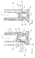
- Fig. 1 shows a sectional view of a neutralization unit according to the invention.
- the neutralization unit has a supply line 2, which opens into a receiving space 4.
- This receiving space 4 can be filled with a neutralizing agent, for example containing dolomite, magnesium oxide or the like.
- the receiving space 4 is filled with a granular neutralizing agent.
- four tubular foot elements 6 extend downwards at the corners. On the circumference, the tubular foot elements and the free spaces between them are covered by an outer wall 8. In the in Fig. 1 As shown, the tubular foot elements are closed on their underside by feet 10. With the stance feet 10, the neutralization unit stands on the ground.
- the interior of the tubular foot elements 6 is connected to the receiving space 4, so that condensate, which flows through the supply line and has flowed through the receiving space 4 and the granules or neutralizing agent disposed therein, enters the tubular feet 10. Since in this embodiment, the tubular foot elements 6 are closed by the feet 10, the condensate can not drain through the tubular foot elements. Therefore, it runs in this arrangement by a lateral outlet opening 12, which is arranged below the bottom 14 of the receiving space 4 at the upper end of the tubular base elements 6. It will thus first fully run the tubular foot member 6 until the condensate then drains through the lateral outlet opening.
- the feet 10 are inserted into the open ends of the tubular foot elements 6, which form a recess 16, so that they can be adjusted in the vertical direction X in order to be able to orient the neutralization unit horizontally so that the bottom 14 extends substantially horizontally.
- all four feet of the neutralization unit which are formed by four tubular foot elements with base feet 10 arranged at the lower end, are designed to be height-adjustable in a corresponding manner.
- a helically extending abutment surface 18 is formed on the inner periphery of the recess 16, which is formed by the interior at the lower end of the tubular base member 6, a helically extending abutment surface 18.
- the contact surface 18 is formed in the form of a radially inwardly directed projection on the inner wall of the recess 16. In this case, the contact surface 18 extends annularly around a central opening 20 around.
- the contact surface 18 has over its circumferential extent a slope S in the vertical direction as in Fig. 2 located. However, the contact surface 18 extends only once around the inner circumference of the recess 16, ie over an angle of ⁇ 360 °.
- the annular and screw-shaped extending contact surface 18 begins and ends at a stop web 22.
- the stop web 22 extends, starting from the inner wall of the recess 16 radially inward transversely to the extension direction of the contact surface 18, ie in the direction of the vertically extending longitudinal axis X of the recess 16th
- the engagement portion 24 has an outer diameter which substantially corresponds to the inner diameter of the recess 16 or is slightly larger, so that the peripheral wall of the engagement portion 24 on the inner peripheral surface of the recess 16 can come to bear sealingly.
- the engagement portion 24 is here also tubular and closed at its lower end by the bottom portion 26 of the base 10. In this way, the base 10, when it is inserted with its engagement portion 24 in the recess 16, the opening of the recess 16 and thus the lower end of the tubular foot member 6 closes tightly. Thus, no liquid can escape from the lower end of the tubular foot member 6.
- the tubular engagement section 24 has an axial projection 28 extending over only a partial region of the circumference.
- the axial projection 28 has a support surface 30.
- the support surface 30 is formed by the axial end face of the projection 28.
- the projection 28 extends as an extension of the peripheral wall of the tubular engagement portion 24 adjacent to the inner periphery of the recess 16.
- the frontal support surface 30 also extends obliquely to the longitudinal axis X and to the horizontal, corresponding helically curved as the contact surface 18 in the recess 16. So can the support surface 30 come to rest flat against the contact surface 18.
- the support surface 30 shifts along the contact surface 18, whereby due to the oblique course or the slope S of the contact surface 18 causes an axial displacement of the base 10 in the vertical direction.
- the height of the Standfu- ⁇ es 10, with which this projecting beyond the lower end of the tubular foot member 6, can be varied.
- the entire neutralization unit can be aligned such that the bottom 14 extends substantially horizontally.
- Fig. 2 the base 10 is shown in a further inserted into the recess 16 position as in Fig. 3 ,
- the angle of rotation of the base 10 in the recess 16 is limited by the stop web 22.
- the axial extent of the tubular engagement portion 24 is longer than the displacement of the base 10 in the axial direction X, ie the slope S. This ensures that even in the position in which stand 10 maximum from the lower end of the tubular Foot member 6 protrudes, the outer peripheral surface of the engaging portion 24 still sealingly abuts the inner peripheral surface of the recess 16 so that the tubular base member 6 remains sealed by the base 10 down.
- the base 10 and in particular the engagement portion 24 are formed of an elastic material, preferably an elastomer or rubber, so that the engagement portion 24 can be inserted under a certain bias in the recess 16 so that it with its outer peripheral surface in sealing engagement with the inner peripheral surface the recess 16 is held.
- the contact surface 18 extends over an angle of less than 360 ° and thus there is no engagement in the manner of a thread, it is also possible to pull the base 10 in the axial direction X from the recess 16 or vice versa in this direction in the recess 16 to insert.
- the base 10 can be inserted in the manner of a plug into the recess 16 in order to close it.
- the feet 10 can be easily removed if the feet 10 are not needed because the neutralization unit is placed for example directly on a lifting unit or a further unit, so that the tubular foot elements 6 are used as outlet lines.
- an inlet opening of a subsequent further assembly such as a lifting unit connect, so that the water or condensate from the tubular foot member 6 can flow directly into the subsequent assembly.
Landscapes
- Engineering & Computer Science (AREA)
- Chemical & Material Sciences (AREA)
- General Engineering & Computer Science (AREA)
- Thermal Sciences (AREA)
- Combustion & Propulsion (AREA)
- Mechanical Engineering (AREA)
- Physics & Mathematics (AREA)
- Life Sciences & Earth Sciences (AREA)
- Hydrology & Water Resources (AREA)
- Environmental & Geological Engineering (AREA)
- Water Supply & Treatment (AREA)
- Organic Chemistry (AREA)
- Sink And Installation For Waste Water (AREA)
Abstract
Die Erfindung betrifft eine Neutralisationseinheit zur Neutralisation von Kondenswasser einer Heizungsanlage, wobei die Neutralisationseinheit an ihrer Unterseite mit Standfüßen (10) versehen ist, wobei zumindest einer der Standfüße (10) in eine Ausnehmung (16) an einer Unterseite der Neutralisationseinheit eingreift und in der Ausnehmung (16) eine Anlagefläche (18) ausgebildet ist, an welcher sich der Standfuß (10) mit einer an dem Standfuß (10) ausgebildeten Stützfläche (30) in vertikaler Richtung (X) abstützt, wobei die Anlagefläche (18) und/oder die Stützfläche (30) sich bogenförmig mit einer Steigung (S) in vertikaler Richtung (X) erstrecken.
Description
- Die Erfindung betrifft eine Neutralisationseinheit zur Neutralisation von Kondenswasser einer Heizungsanlage, wobei die Neutralisationseinheit an ihrer Unterseite mit Standfüßen versehen ist.
- Bekannte Neutralisationseinheiten sind üblicherweise als Behälter ausgebildet, in welchem ein Neutralisationsmittel, beispielsweise Kalkstein, Dolomit und/oder Magnesiumoxid oder ähnliches enthaltend, angeordnet ist. Durch dieses Neutralisationsmittel wird das Kondensat geleitet, um dieses zu neutralisieren, d. h. dessen PH-Wert zu erhöhen. Um den gewünschten Durchfluss des Kondensats durch die Neutralisationseinheit bzw. durch einen in der Neutralisationseinheit angeordneten Behälter mit Neutralisationsmittel zu gewährleisten, ist es erforderlich die Neutralisationseinheit beim Aufstellen auf einer Standfläche horizontal auszurichten, damit die Strömungswege im Inneren das gewünschte Gefälle aufweisen. Auf unebenen Untergrund ist es nicht immer einfach möglich, eine solche Neutralisationseinheit in der gewünschten Weise horizontal auszurichten.
- Es ist daher Aufgabe der Erfindung, eine Neutralisationseinheit zur Neutralisation von Kondenswasser einer Heizungsanlage dahingehend zu verbessern, dass sie auf einfache Weise ausgerichtet werden kann.
- Diese Aufgabe wird durch eine Neutralisationseinheit zur Neutralisation von Kondenswasser einer Heizungsanlage mit den in Anspruch 1 angegebenen Merkmalen gelöst. Bevorzugte Ausführungsformen ergeben sich aus den Unteransprüchen, der nachfolgenden Beschreibung sowie den beigefügten Figuren.
- Die erfindungsgemäße Neutralisationseinheit weist an ihrer Unterseite Standfüße auf, mittels welcher sie auf dem Boden, d. h. einer Standfläche, aufgestellt werden kann. Beispielsweise können drei oder vier Standfüße vorgesehen sein. Wenn die Neutralisationseinheit einen im Wesentlichen rechteckigen Querschnitt aufweist, sind vorzugsweise vier Standfüße vorgesehen, wobei die Standfüße jeweils in der Nähe einer Ecke der Grundfläche angeordnet sind.
- Erfindungsgemäß ist zumindest einer der Standfüße in eine Ausnehmung an der Unterseite der Neutralisationseinheit eingesetzt. Dabei ist der Standfuß vorzugsweise von unten in einer Richtung quer zur Unterseite in Längsrichtung der Ausnehmung in diese eingesetzt. An dem Standfuß ist eine Stützfläche ausgebildet, mit welcher sich der Standfuß in vertikaler Richtung an einer Anlagefläche abstützt, welche im Inneren der Ausnehmung ausgebildet ist. So werden die Gewichtskräfte der Neutralisationseinheit durch die Anlagefläche auf die Stützfläche des Standfu-βes übertragen, sodass der Standfuß die Kräfte dann auf die unter ihm liegende Fläche übertragen kann. Die Anlagefläche oder alternativ die Stützfläche oder aber beide Flächen erstrecken sich erfindungsgemäß bogenförmig und zumindest eine der Flächen, d. h. der Stützfläche und der Anlagefläche ist in vertikaler Richtung mit einer Steigung versehen. D. h. zumindest eine der Flächen bildet den Abschnitt einer schraubenförmigen Bahn. Dadurch wird erreicht, dass durch Änderung der Winkelposition des Standfußes in der Ausnehmung gleichzeitig die Lage des Standfußes in Richtung der Längsachse der Ausnehmung geändert wird, d. h. insbesondere die vertikale Position der Unterseite des Standfußes relativ zu der Ausnehmung bzw. der Unterseite der Neutralisationseinheit verändert wird. D. h. durch Änderung der Winkelposition um die sich quer zur Unterseite erstreckende Längsachse der Ausnehmung wird das Maß geändert, um welches der Standfuß nach außen aus der Ausnehmung vorsteht. Auf diese Weise kann die Höhe des Standfußes angepasst werden und so eine Ausrichtung der Neutralisationseinheit in vertikaler Richtung an der Position des Standfußes erreicht werden. Durch Veränderung der Höhe des Standfußes an einer Seite oder Ecke der Neutralisationseinheit kann diese in gewünschter Weise horizontal ausgerichtet werden, sodass sie eine vorbestimmte Lage bezüglich der Horizontalen, vorzugsweise in zwei Richtungen, einnimmt.
- Vorzugsweise sind mehrere oder besonders bevorzugt alle Standfüße der Neutralisationseinheit jeweils in der vorangehend beschrieben Weise in eine Ausnehmung an einer Unterseite der Neutralisationseinheit eingesetzt. D. h. jeder der Standfüße greift in eine Ausnehmung ein, wobei in der Ausnehmung jeweils eine Anlagefläche ausgebildet ist, an welcher sich der Standfuß mit einer an dem Standfuß ausgebildeten Stützfläche in vertikaler Richtung abstützt, wobei die Anlagefläche und/oder die Stützfläche sich bogenförmig mit einer Steigung in vertikaler Richtung erstrecken. Auf diese Weise können mehrere oder alle Standfüße durch Drehung in der vorangehend beschriebenen Weise weiter in die Ausnehmung herein bewegt oder weiter aus der Ausnehmung heraus bewegt werden, wobei die vertikale Höhe der Standfüße verändert wird. So wird eine noch genauere Ausrichtung der Neutralisationseinheit und Anpassung an unebene bzw. schräge Aufstellflächen möglich.
- Besonders bevorzugt ist der Standfuß in der Ausnehmung drehbar. So wird eine Ausrichtung in vertikaler Richtung durch einfache Drehung des Standfußes möglich. Dabei gleiten die Stützfläche und die Anlagefläche vorzugsweise aneinander entlang und es kommt aufgrund der beschriebenen Steigung zu einer Verlagerung des Standfußes in Längsrichtung der Ausnehmung, d. h. vorzugsweise in vertikaler Richtung. Um den Standfuß leicht drehen zu können, ist dieser vorzugsweise in einem Abschnitt, welcher aus der Ausnehmung herausragt, mit einer Riffelung bzw. Strukturierung am Außenumfang versehen, sodass er leicht ergriffen werden kann. Er könnten in diesem Abschnitt auch Anlageflächen für ein Werkzeug, beispielsweise für einen Schraubenschlüssel ausgebildet sein, um den Standfuß leicht drehen zu können.
- Weiter bevorzugt ist zwischen der Ausnehmung und dem Standfuß zumindest ein Anschlag angeordnet, welcher den Drehwinkel zwischen der Ausnehmung und dem Standfuß begrenzt. Der zugelassene Drehwinkel ist vorzugsweise < 360°. Besonders bevorzugt sind zwei Anschläge vorgesehen, welche zwei Endlagen für die Drehbewegung definieren. So entspricht eine Endlage aufgrund der Steigung der Anlagefläche und/oder der Stützfläche der Position, an welcher der Standfuß minimal aus der Ausnehmung nach außen auskragt, und die andere Endlage der Position, an welcher der Standfuß maximal aus der Ausnehmung nach außen auskragt. Aufgrund des begrenzten Drehwinkels von < 360° ist die bogeförmige und ansteigende Fläche so ausgebildet, dass sie weniger als eine Schraubenwindung darstellt. Mit ausreichend großer Steigung kann so ein großer axialer Verstellweg des Standfußes bei kleiner Drehung erreicht werden.
- Um die Drehung des Standfußes in der Ausnehmung zu ermöglichen, weisen die Ausnehmung und ein in die Ausnehmung eingreifender Abschnitt des Standfußes vorzugsweise einen kreisförmigen Querschnitt auf. Der kreisförmige Querschnitt erstreckt sich konzentrisch um die Längsachse der Ausnehmung, vorzugsweise die vertikale Achse, entlang derer der Standfuß in der Ausnehmung axial verstellt wird. Vorzugsweise liegt die Außenumfangsfläche des Standfußes an einer Innenumfangsfläche der Ausnehmung an, sodass diese ineinander geführt sind.
- Besonders bevorzugt ist der Standfuß aus der Ausnehmung axial entnehmbar. Dies ist insbesondere dann möglich, wenn die Stützfläche und die Anlagefläche sich lediglich über einen Bogen von < 360° erstrecken, da dann kein gewindeähnlicher Eingriff zwischen beiden erzielt wird. Die axiale Entnehmbarkeit ermöglicht es, die Standfüße leicht abzunehmen, wenn sie nicht benötigt werden, beispielsweise weil die Neutralisationseinheit an der Wand befestigt wird oder auf eine andere Baugruppe, wie beispielsweise eine Hebeeinheit von oben aufgesetzt wird. Auch sind die Standfüße auf diese Weise leicht montierbar, da sie in axialer Richtung einfach in die Ausnehmungen eingesteckt werden können und zur Montage nicht geschraubt werden müssen.
- Bevorzugt ist der Standfuß aus einem elastischen Material gefertigt. Auf diese Weise wird eine Dämpfung beim Aufstellen erreicht, darüber hinaus eine Rutschfestigkeit der Aufstellfläche gewährleistet. Darüber hinaus kann auf diese Weise eine gewisse Klemmung in der Ausnehmung erreicht werden, welche ein unerwünschtes Verdrehen oder axiales Verschieben des Standfußes in der Ausnehmung verhindert.
- Gemäß einer besonders bevorzugten Ausführungsform der Erfindung wird die Ausnehmung von einer stirnseitigen Öffnung und einen Innenraum eines rohrförmigen Fußelementes gebildet. Bevorzugt weist die Neutralisationseinheit mehrere, insbesondere vier derartige Fußelemente auf, an deren Unterseite jeweils ein Standfuß gemäß der vorangehenden Beschreibung in die stirnseitige Öffnung des rohrförmigen Fußelementes eingesetzt ist, sodass das Fußelement aus der stirnseitigen Öffnung nach unten vorsteht. Im Innenraum des rohrförmigen Fußelementes ist dann die oben beschriebene Anlagefläche ausgebildet.
- Ein solches rohrförmiges Fußelement kann gleichzeitig ein Austrittsrohr der Neutralisationseinheit bilden. Bevorzugt sind mehrere, insbesondere vier derartige Fußelemente vorgesehen, wobei zumindest eines, bevorzugt jedoch alle dieser Fußelemente die Funktion eines Austrittsrohres der Neutralisationseinheit bilden. Aus diesen Austrittsrohren tritt dann das neutralisierte Kondensat aus, um entweder einem Abfluss oder gegebenenfalls einer nachfolgend angeordneten Hebeeinheit zugeleitet zu werden, welche das Kondensat dann in eine Abflussleitung pumpt.
- Die Standfüße sind bevorzugt so ausgebildet, dass sie die Ausnehmung, in welche sie eingesetzt sind, nach außen abdichten. Dies ermöglicht es, dass der Standfuß, dann wenn die Ausnehmung gleichzeitig eine Austrittsöffnung bildet, dazu verwendet werden kann, die Ausnehmung nach außen dicht zu verschließen. Es kann beispielsweise, wenn die Neutralisationseinheit direkt auf eine Hebeeinheit aufgesetzt wird, der Standfuß aus der Ausnehmung entnommen werden, sodass die Ausnehmung offen ausgebildet ist und als Austrittsöffnung fungieren kann, aus welcher das neutralisierte Kondensat austritt und in die darunterliegende Hebeeinheit eintritt. Wenn jedoch dieselbe Neutralisationseinheit auf dem Boden aufgestellt wird, kann durch Einsetzen des Standfußes in die Ausnehmung bzw. das die Ausnehmung bildende Austrittsrohr die Ausnehmung verschlossen werden, sodass das Kondensat dort nicht austreten kann. Zum Austritt des Kondensats kann dann eine spezielle, beispielsweise seitlich angeordnete Austrittsöffnung verwendet werden, welche dann geöffnet wird. Dies bedeutet, dass der Standfuß eine Doppelfunktion übernimmt, zum einen die Ausrichtung der Neutralisationseinheit in horizontaler Richtung ermöglicht und zum anderen gleichzeitig den dichten Verschluss eines Austrittsrohres bzw. einer Austrittsöffnung dient, wenn diese nicht benötigt wird. Dabei ist es zweckmäßig, wenn der Standfuß aus einem elastischen Material gefertigt ist, da er dann nach Art eines elastischen Stopfens in die Ausnehmung dichtend eingesetzt werden kann. Alternativ kann der Standfuß an seiner Umfangsfläche eine Dichtung, z. B. einen O-Ring aufweisen, welche dicht an einer Wandung der Ausnehmung anliegt.
- Um die Funktion als Austrittsrohr bzw. Austrittsleitung der Ausnehmung sicherzustellen, ist es bevorzugt, dass die Anlagefläche in der Ausnehmung sich bogen- oder ringförmig um eine zentrale Öffnung erstreckt. Die zentrale Öffnung definiert einen Strömungsweg, durch welchen Kondensat an der Anlagefläche vorbei aus der Ausnehmung austreten kann.
- Die Stützfläche an dem Standfuß wird vorzugsweise von der Stirnseite eines axialen Vorsprunges des Standfußes gebildet. Die Seitenflächen dieses axialen Vorsprunges können gleichzeitig Anschläge bilden, welche den Drehwinkel des Standfußes begrenzen. Dazu kann eine korrespondiere Anschlagfläche oder ein Anschlagelement in Form eines radial nach innen gerichteten Vorsprunges an einer Umfangswandung der Ausnehmung vorgesehen sein, an welche der Vorsprung mit seinen Seitenflächen anschlägt.
- Der Standfuß weist weiter bevorzugt eine ringförmige Kontaktfläche auf, welche an einer Innenwandung der Ausnehmung dichtend anliegt. Dies ist vorzugsweise ein Bereich der Innenwandung der Ausnehmung, welcher zwischen der schraubenabschnittförmigen Anlagefläche der Ausnehmung und der Öffnung der Ausnehmung, durch welche sich der Standfuß nach außen erstreckt, gelegen ist. Die Anlage- bzw. Kontaktfläche des Standfußes weist dabei eine axiale Länge auf, welche größer ist als die Steigung der Anlagefläche und/oder der Steigung der Stützfläche. D. h. die Kontaktfläche ist länger als der axiale Verstellweg des Standfußes in der Ausnehmung. Auf diese Weise wird sichergestellt, dass auch dann, wenn der Standfuß in seiner maximal aus der Ausnehmung nach außen hervorstehenden Position befindet, eine dichtende Anlage zwischen der Kontaktfläche und der Innenwandung der Ausnehmung gegeben ist, sodass die Ausnehmung nach außen dicht verschlossen ist. An der ringförmigen Kontaktfläche können Dichtungsringe ausgebildet oder angeordnet sein, welche dichtend an der Innenwandung der Ausnehmung anliegen.
- Nachfolgend wird die Erfindung beispielhaft anhand der beigefügten Figuren beschrieben. In diesen zeigt:
- Fig. 1
- eine Schnittansicht einer erfindungsgemäßen Neutralisationseinheit,
- Fig. 2
- eine Detailansicht eines Standfußes der Neutrolisationseinheit gemäß
Fig. 1 im Schnitt und - Fig. 3
- eine Detailansicht eines Standfußes in einer gegenüber
Fig. 2 entgegengesetzt gerichteten Schnittansicht. -
Fig. 1 zeigt eine Schnittansicht einer erfindungsgemäßen Neutralisationseinheit. Die Neutralisationseinheit weist eine Zuführleitung 2 auf, welche in einen Aufnahmeraum 4 mündet. Dieser Aufnahmeraum 4 kann mit einem Neutralisationsmittel, beispielsweise Dolomit, Magnesiumoxid oder ähnliches enthaltend gefüllt werden. Vorzugsweise ist der Aufnahmeraum 4 mit einem granulatförmigen Neutralisationsmittel gefüllt. Ausgehend von dem Aufnahmeraum 4 erstrecken sich an den Ecken vier rohrförmige Fußelemente 6 nach unten. Umfangsseitig sind die rohrförmigen Fußelemente und die Freiräume zwischen ihnen durch eine Außenwand 8 verkleidet. In dem inFig. 1 gezeigten Beispiel sind die rohrförmigen Fußelemente an ihrer Unterseite durch Standfüße 10 verschlossen. Mit den Stanfüßen 10 steht die Neutralisationseinheit auf dem Boden auf. Das Innere der rohrförmigen Fußelemente 6 ist mit dem Aufnahmeraum 4 verbunden, sodass Kondensat, welches durch die Zuführleitung einströmt und durch den Aufnahmeraum 4 und das darin angeordnete Granulat bzw. Neutralisationsmittel geflossen ist, in die rohrförmigen Standfüße 10 einläuft. Da in diesem Ausführungsbeispiel die rohrförmigen Fußelemente 6 durch die Standfüße 10 verschlossen sind, kann das Kondensat nicht durch die rohrförmigen Fußelemente ablaufen. Daher läuft es bei dieser Anordnung durch eine seitliche Austrittsöffnung 12 ab, welche unterhalb des Bodens 14 des Aufnahmeraumes 4 am oberen Ende der rohrförmigen Fußelemente 6 angeordnet ist. Es wird somit zunächst das rohrförmige Fußelement 6 voll laufen bis das Kondensat dann durch die seitliche Austrittsöffnung abläuft. - Erfindungsgemäß sind die Standfüße 10 so in die offenen Enden der rohrförmigen Fußelemente 6, welche eine Ausnehmung 16 bilden, eingesetzt, dass sie in vertikaler Richtung X verstellbar sind, um die Neutralisationseinheit horizontal ausrichten zu können, sodass sich der Boden 14 im Wesentlichen horizontal erstreckt. Dafür sind alle vier Füße der Neutralisationseinheit, welche durch vier rohrförmige Fußelemente mit daran am unteren Ende angeordneten Standfüßen 10 gebildet werden, in entsprechender Weise höhenverstellbar ausgebildet.
- Wie in
Fig. 2 zu erkennen ist, ist am Innenumfang der Ausnehmung 16, welche vom Innenraum am unteren Ende des rohrförmigen Fußelementes 6 gebildet wird, eine sich schraubenförmig erstreckende Anlagefläche 18 ausgebildet. Die Anlagefläche 18 ist in Form eines radial nach innen gerichteten Vorsprunges an der Innenwand der Ausnehmung 16 ausgebildet. Dabei erstreckt sich die Anlagefläche 18 ringförmig um eine zentrale Öffnung 20 herum. Die Anlagefläche 18 hat über ihre umfängliche Erstreckung eine Steigung S in vertikaler Richtung wie inFig. 2 eingezeichnet. Die Anlagefläche 18 erstreckt sich dabei jedoch lediglich einmal um den Innenumfang der Ausnehmung 16, d. h. über einen Winkel von < 360°. - Die ringförmig und schraubenabschnittsförmig verlaufende Anlagefläche 18 beginnt und endet an einem Anschlagsteg 22. Der Anschlagsteg 22 erstreckt sich ausgehend von der Innenwandung der Ausnehmung 16 radial nach Innen quer zur Erstreckungsrichtung der Anlagefläche 18, d. h. in Richtung der sich vertikal erstreckenden Längsachse X der Ausnehmung 16.
- In die Ausnehmung 16 greift der Standfuß 10 mit einem im Querschnitt kreisförmigen Eingriffsabschnitt 24 ein. Dabei weist der Eingriffsabschnitt 24 einen Außendurchmesser auf, welcher im Wesentlichen dem Innendurchmesser der Ausnehmung 16 entspricht oder geringfügig größer ist, sodass die Umfangswandung des Eingriffsabschnittes 24 an der Innenumfangsfläche des Ausnehmung 16 dichtend zur Anlage kommen kann. Der Eingriffsabschnitt 24 ist hier ebenfalls rohrförmig ausgebildet und an seinem unteren Ende durch den Bodenabschnitt 26 des Standfußes 10 verschlossen. Auf diese Weise verschließt der Standfuß 10, wenn er mit seinem Eingriffsabschnitt 24 in die Ausnehmung 16 eingesetzt ist, die Öffnung der Ausnehmung 16 und somit das untere Ende des rohrförmigen Fußelementes 6 dicht. So kann keine Flüssigkeit mehr aus dem unteren Ende des rohrförmigen Fußelementes 6 austreten.
- An seinem dem Bodenabschnitt 6 abgewandten Ende weist der rohrförmige Eingriffsabschnitt 24 einen sich nur über einen Teilbereich des Umfanges erstreckenden axialen Vorsprung 28 auf. An seinem dem Eingriffsabschnitt 24 abgewandten freien Axialenden weist der axiale Vorsprung 28 eine Stützfläche 30 auf. Die Stützfläche 30 wird von der axialen Stirnfläche des Vorsprunges 28 gebildet. Der Vorsprung 28 erstreckt sich als Verlängerung der Umfangswandung des rohrförmigen Eingriffsabschnittes 24 angrenzend an den Innenumfang der Ausnehmung 16. Die stirnseitige Stützfläche 30 verläuft dabei ebenfalls schräg zur Längsachse X und zur Horizontalen, korrespondierend schraubenförmig gekrümmt wie die Anlagefläche 18 in der Ausnehmung 16. So kann die Stützfläche 30 flächig an der Anlagefläche 18 zur Anlage kommen.
- Wenn der Standfuß in der Ausnehmung 16 um die Längsachse X gedreht wird, verschiebt sich die Stützfläche 30 entlang der Anlagefläche 18, wodurch aufgrund des schrägen Verlaufes bzw. der Steigung S der Anlagefläche 18 eine axiale Verschiebung des Standfußes 10 in vertikaler Richtung bewirkt wird. Auf diese Weise kann die Höhe des Standfu-βes 10, mit welcher dieser über das untere Ende des rohrförmigen Fußelementes 6 nach unten vorsteht, variiert werden. So lässt sich die gesamte Neutralisationseinheit derart ausrichten, dass der Boden 14 im Wesentlichen horizontal erstreckt.
- In
Fig. 2 ist der Standfuß 10 in einer weiter in die Ausnehmung 16 eingeschobenen Position gezeigt als inFig. 3 . Der Drehwinkel des Standfußes 10 in der Ausnehmung 16 wird durch den Anschlagsteg 22 begrenzt. Jeweils eine der sich im Wesentlichen radial bezüglich der Längsachse X erstreckenden Seitenflächen des Vorsprunges 28 kommt in einer Endlage an diesem Anschlagsteg 22 zur Anlage, wodurch dann eine weitere Drehung des Standfußes 10 in der Ausnehmung 16 in diese Drehrichtung blockiert wird. - Wir in
Fig. 2 und 3 zu sehen ist, ist die axiale Ausdehnung des rohrförmigen Eingriffsabschnittes 24 länger als der Verstellweg des Standfußes 10 in axialer Richtung X, d. h. die Steigung S. Dadurch wird erreicht, dass auch in der Position, in welcher Standfuß 10 maximal aus dem unteren Ende des rohrförmigen Fußelementes 6 hervorsteht, die Außenumfangsfläche des Eingriffsabschnittes 24 immer noch dichtend an der Innenumfangsfläche der Ausnehmung 16 anliegt, sodass das rohrförmige Fußelement 6 durch den Standfuß 10 nach unten dicht verschlossen bleibt. Der Standfuß 10 und insbesondere der Eingriffsabschnitt 24 sind aus einem elastischen Material, vorzugsweise einem Elastomer oder Gummi gebildet, sodass der Eingriffsabschnitt 24 unter einer gewissen Vorspannung in die Ausnehmung 16 eingesetzt werden kann, sodass er mit seiner Außenumfangsfläche in dichtender Anlage an der Innenumfangsfläche der Ausnehmung 16 gehalten wird. Zusätzlich sind an dem Eingriffsabschnitt 24 am Außenumfang ringförmige Vorsprünge 32 ausgebildet, welche die Funktion eines Dichtringes haben und in dichter Anlage an die Innenumfangsfläche der Ausnehmung 16 gepresst werden. Es wäre auch möglich, zur Abdichtung nur die Vorsprünge 32 aus einem elastischen Material zu fertigen. - Da die Anlagefläche 18 sich über einen Winkel von weniger als 360° erstreckt und es somit keinen Eingriff nach Art eines Gewindes gibt, ist es weiterhin möglich, den Standfuß 10 in axialer Richtung X aus der Ausnehmung 16 herauszuziehen oder umgekehrt in dieser Richtung in die Ausnehmung 16 einzustecken. So kann der Standfuß 10 nach Art eines Stopfens in die Ausnehmung 16 eingesteckt werden, um diese zu verschließen. Umgekehrt kann er leicht entnommen werden, wenn die Standfüße 10 nicht benötigt werden, weil die Neutralisationseinheit beispielsweise direkt auf eine Hebeeinheit oder eine weiter Baueinheit aufgesetzt wird, sodass die rohrförmigen Fußelemente 6 als Austrittsleitungen genutzt werden. So kann sich an das untere Ende der Ausnehmung 16, welche dann geöffnet ist, eine Eintrittsöffnung einer sich anschließenden weiteren Baugruppe, beispielsweise einer Hebeeinheit anschließen, sodass das Wasser bzw. Kondensat aus dem rohrförmigen Fußelement 6 direkt in die sich anschließende Baugruppe fließen kann. Durch die zentrale Öffnung 20 in der Anlagefläche 18 ist dabei der Ausfluss von Kondensat aus dem unteren Ende des rohrförmigen Fußelementes 6 weiter gewährleistet.
-
- 2
- Zuführleitung
- 4
- Aufnahmeraum
- 6
- Rohrförmige Fußelemente
- 8
- Außenwand
- 10
- Standfuß
- 12
- Austrittsöffnung
- 14
- Boden
- 16
- Ausnehmung
- 18
- Anlagefläche
- 20
- Zentrale Öffnung
- 22
- Anschlagsteg
- 24
- Eingriffsabschnitt
- 26
- Bodenabschnitt
- 28
- Axialer Vorsprung
- 30
- Stützfläche
- 32
- Ringförmige Vorsprünge
- S
- Steigung
- X
- Längsachse
Claims (14)
- Neutralisationseinheit zur Neutralisation von Kondenswasser einer Heizungsanlage, wobei die Neutralisationseinheit an ihrer Unterseite mit Standfüßen (10) versehen ist,
dadurch gekennzeichnet, dass
zumindest einer der Standfüße (10) in eine Ausnehmung (16) an einer Unterseite der Neutralisationseinheit eingreift und in der Ausnehmung (16) eine Anlagefläche (18) ausgebildet ist, an welcher sich der Standfuß (10) mit einer an dem Standfuß (10) ausgebildeten Stützfläche (30) in vertikaler Richtung (X) abstützt, wobei die Anlagefläche (18) und/oder die Stützfläche (30) sich bogenförmig mit einer Steigung (S) in vertikaler Richtung (X) erstrecken. - Neutralisationseinheit nach Anspruch 1, dadurch gekennzeichnet, dass mehrere und vorzugsweise alle Standfüße (10) jeweils in eine Ausnehmung (16) an einer Unterseite der Neutralisationseinheit eingreifen und in der Ausnehmung (16) jeweils eine Anlagefläche (18) ausgebildet ist, an welcher sich der Standfuß (10) mit einer an dem Standfuß (10) ausgebildeten Stützfläche (30) in vertikaler Richtung (X) abstützt, wobei die Anlagefläche (18) und/oder die Stützfläche (30) sich bogenförmig mit einer Steigung (S) in vertikaler Richtung (X) erstrecken.
- Neutralisationseinheit nach Anspruch 1 oder 2, dadurch gekennzeichnet, dass der Standfuß (10) in der Ausnehmung (16) drehbar ist.
- Neutralisationseinheit nach einem der vorangehenden Ansprüche,
dadurch gekennzeichnet, dass zwischen der Ausnehmung (16) und dem Standfuß (10) zumindest ein Anschlag (22) angeordnet ist, welcher den Drehwinkel zwischen der Ausnehmung (16) und dem Standfuß (10) begrenzt. - Neutralisationseinheit nach einem der vorangehenden Ansprüche,
dadurch gekennzeichnet, dass die Ausnehmung (16) und ein in die Ausnehmung (16) eingreifender Abschnitt (24) des Standfußes (10) einen kreisförmigen Querschnitt aufweisen. - Neutralisationseinheit nach einem der vorangehenden Ansprüche,
dadurch gekennzeichnet, dass der Standfuß (10) aus der Ausnehmung (16) axial (X) entnehmbarist. - Neutralisationseinheit nach einem der vorangehenden Ansprüche,
dadurch gekennzeichnet, dass der Standfuß (10) aus einem elastischen Material gefertigt ist. - Neutralisationseinheit nach Anspruch 7, dadurch gekennzeichnet, dass der Standfuß (10) aus einem Elastomer oder Gummi gefertigt ist.
- Neutralisationseinheit nach einem der vorangehenden Ansprüche,
dadurch gekennzeichnet, dass die Ausnehmung (16) von einer stirnseitigen Öffnung und einem Innenraum eines rohrförmigen Fußelementes (6) gebildet wird. - Neutralisationseinheit nach Anspruch 9, dadurch gekennzeichnet, dass das rohrförmige Fußelement (6) ein Austrittsrohr der Neutralisationseinheit ist.
- Neutralisationseinheit nach einem der vorangehenden Ansprüche,
dadurch gekennzeichnet, dass der Standfuß (10) die Ausnehmung (16) nach außen dicht verschließt. - Neutralisationseinheit nach einem der vorangehenden Ansprüche,
dadurch gekennzeichnet, dass die Anlagefläche (18) in der Ausnehmung (16) sich bogen- oder ringförmig um eine zentrale Öffnung (20) erstreckt. - Neutralisationseinheit nach einem der vorangehenden Ansprüche,
dadurch gekennzeichnet, dass die Stützfläche (30) von der Stirnseite eines axialen Vorsprunges (28) des Standfußes (10) gebildet wird. - Neutralisationseinheit nach einem der vorangehenden Ansprüche,
dadurch gekennzeichnet, dass der Standfuß (10) eine ringförmige KOntaktfläche aufweist, welche an einer Innenwandung der Ausnehmung (16) dichtend anliegt, wobei die Kontaktfläche eine axiale Länge aufweist, welche größer ist als die Steigung (S) der Anlage- (18) und/oderStützfläche (30).
Priority Applications (1)
| Application Number | Priority Date | Filing Date | Title |
|---|---|---|---|
| EP11182389A EP2573483A1 (de) | 2011-09-22 | 2011-09-22 | Neutralisationseinheit |
Applications Claiming Priority (1)
| Application Number | Priority Date | Filing Date | Title |
|---|---|---|---|
| EP11182389A EP2573483A1 (de) | 2011-09-22 | 2011-09-22 | Neutralisationseinheit |
Publications (1)
| Publication Number | Publication Date |
|---|---|
| EP2573483A1 true EP2573483A1 (de) | 2013-03-27 |
Family
ID=44674555
Family Applications (1)
| Application Number | Title | Priority Date | Filing Date |
|---|---|---|---|
| EP11182389A Withdrawn EP2573483A1 (de) | 2011-09-22 | 2011-09-22 | Neutralisationseinheit |
Country Status (1)
| Country | Link |
|---|---|
| EP (1) | EP2573483A1 (de) |
Citations (5)
| Publication number | Priority date | Publication date | Assignee | Title |
|---|---|---|---|---|
| US3844518A (en) * | 1973-04-18 | 1974-10-29 | Westinghouse Electric Corp | Leveling support structure for dishwasher |
| EP0034135A1 (de) * | 1980-02-08 | 1981-08-19 | Aktiebolaget Electrolux | Haushaltsvorrichtung |
| FR2532042A1 (fr) * | 1982-08-17 | 1984-02-24 | Lorraine Cie Solaire | Support pour chauffe-eau a accumulation, pose au sol |
| EP0292416A2 (de) * | 1987-05-20 | 1988-11-23 | De Dietrich Thermique | Einstellbare Fusseinrichtung für Hausöfen und Wassererhitzer aus Gusseisen |
| EP0614057A2 (de) * | 1993-03-05 | 1994-09-07 | Armin Frischknecht | Boileranordnung |
-
2011
- 2011-09-22 EP EP11182389A patent/EP2573483A1/de not_active Withdrawn
Patent Citations (5)
| Publication number | Priority date | Publication date | Assignee | Title |
|---|---|---|---|---|
| US3844518A (en) * | 1973-04-18 | 1974-10-29 | Westinghouse Electric Corp | Leveling support structure for dishwasher |
| EP0034135A1 (de) * | 1980-02-08 | 1981-08-19 | Aktiebolaget Electrolux | Haushaltsvorrichtung |
| FR2532042A1 (fr) * | 1982-08-17 | 1984-02-24 | Lorraine Cie Solaire | Support pour chauffe-eau a accumulation, pose au sol |
| EP0292416A2 (de) * | 1987-05-20 | 1988-11-23 | De Dietrich Thermique | Einstellbare Fusseinrichtung für Hausöfen und Wassererhitzer aus Gusseisen |
| EP0614057A2 (de) * | 1993-03-05 | 1994-09-07 | Armin Frischknecht | Boileranordnung |
Similar Documents
| Publication | Publication Date | Title |
|---|---|---|
| DE10028655B4 (de) | Rohrverbindung und eine solche Rohrverbindung aufweisende, höhenverstellbare Hydranten | |
| EP2054132A1 (de) | Ölfilteranordnung und filterelement hierfür | |
| AT509361B1 (de) | Spindellagerung | |
| EP2183509B1 (de) | Vorrichtung zur drosselung des freien querschnittes einer dampfleitung oder dergleichen | |
| EP3400342B1 (de) | Ventilarmatur für die befüllung eines sanitären spülkastens und sanitärer spülkasten mit einer solchen ventilarmatur | |
| DE4433812C2 (de) | Schlauchanschluß zum Anschluß eines Schlauches, insbesondere eines Gartenschlauches, an einem Anschlußnippel | |
| DE202005004196U1 (de) | Durchflussmengenregler | |
| WO2005047754A1 (de) | Abziehbare adapter-kupplung | |
| DE202011102932U1 (de) | Frostsicheres Außenwandventil für tiefe Temperaturen | |
| DE102011003537B4 (de) | Ventilgehäusekörper | |
| EP3237786B1 (de) | Dichteinsatz für einen wasserablauf | |
| DE102014003497A1 (de) | Gebäudeöffnungsverschattungsvorrichtung und Achskappenmodul für die Wickelwelle der Gebäudeöffnungsverschattungsvorrichtung | |
| DE10106140B4 (de) | Montagewerkzeug für Zentralverschlüsse zum Befestigen von Rädern an einem Kraftfahrzeug | |
| DE4420436C2 (de) | Sanitärarmatur, insbesondere Küchenmischbatterie | |
| DE102010027444B3 (de) | Kabelzugentlastung und Dichtungssystem | |
| AT413237B (de) | Absperrschieber für druckrohrleitungen | |
| EP4247513B1 (de) | Anschlussbaugruppe für einen wasserfilter | |
| DE3737162C2 (de) | ||
| DE202006012819U1 (de) | Rohrelement mit Revisionsöffnung | |
| CH705932A2 (de) | Drehmomentbegrenzungsvorrichtung für Hydranten und Armaturen. | |
| DE202024107441U1 (de) | Verbindung für wasserführende Bauteile | |
| EP2430343B1 (de) | Vorrichtung zur einbringung einer absperreinrichtung in eine rohrleitung | |
| EP3824143B1 (de) | Wandbefestigung mit brausenstangenrohr | |
| DE4423856C2 (de) | Mischventil mit einem Zusatzgerät | |
| WO2025118003A1 (de) | Vorrichtung zur verbindung einer sanitärarmatur mit einer fluidleitung |
Legal Events
| Date | Code | Title | Description |
|---|---|---|---|
| PUAI | Public reference made under article 153(3) epc to a published international application that has entered the european phase |
Free format text: ORIGINAL CODE: 0009012 |
|
| AK | Designated contracting states |
Kind code of ref document: A1 Designated state(s): AL AT BE BG CH CY CZ DE DK EE ES FI FR GB GR HR HU IE IS IT LI LT LU LV MC MK MT NL NO PL PT RO RS SE SI SK SM TR |
|
| AX | Request for extension of the european patent |
Extension state: BA ME |
|
| 17P | Request for examination filed |
Effective date: 20130216 |
|
| STAA | Information on the status of an ep patent application or granted ep patent |
Free format text: STATUS: THE APPLICATION IS DEEMED TO BE WITHDRAWN |
|
| 18D | Application deemed to be withdrawn |
Effective date: 20160401 |