EP2573460A2 - Light source unit, light source device including light source unit, and luminaire including light source device - Google Patents
Light source unit, light source device including light source unit, and luminaire including light source device Download PDFInfo
- Publication number
- EP2573460A2 EP2573460A2 EP12179044A EP12179044A EP2573460A2 EP 2573460 A2 EP2573460 A2 EP 2573460A2 EP 12179044 A EP12179044 A EP 12179044A EP 12179044 A EP12179044 A EP 12179044A EP 2573460 A2 EP2573460 A2 EP 2573460A2
- Authority
- EP
- European Patent Office
- Prior art keywords
- light source
- main body
- section
- source module
- setting surface
- Prior art date
- Legal status (The legal status is an assumption and is not a legal conclusion. Google has not performed a legal analysis and makes no representation as to the accuracy of the status listed.)
- Withdrawn
Links
Images




Classifications
-
- F—MECHANICAL ENGINEERING; LIGHTING; HEATING; WEAPONS; BLASTING
- F21—LIGHTING
- F21V—FUNCTIONAL FEATURES OR DETAILS OF LIGHTING DEVICES OR SYSTEMS THEREOF; STRUCTURAL COMBINATIONS OF LIGHTING DEVICES WITH OTHER ARTICLES, NOT OTHERWISE PROVIDED FOR
- F21V29/00—Protecting lighting devices from thermal damage; Cooling or heating arrangements specially adapted for lighting devices or systems
- F21V29/50—Cooling arrangements
- F21V29/70—Cooling arrangements characterised by passive heat-dissipating elements, e.g. heat-sinks
- F21V29/74—Cooling arrangements characterised by passive heat-dissipating elements, e.g. heat-sinks with fins or blades
- F21V29/77—Cooling arrangements characterised by passive heat-dissipating elements, e.g. heat-sinks with fins or blades with essentially identical diverging planar fins or blades, e.g. with fan-like or star-like cross-section
- F21V29/773—Cooling arrangements characterised by passive heat-dissipating elements, e.g. heat-sinks with fins or blades with essentially identical diverging planar fins or blades, e.g. with fan-like or star-like cross-section the planes containing the fins or blades having the direction of the light emitting axis
-
- F—MECHANICAL ENGINEERING; LIGHTING; HEATING; WEAPONS; BLASTING
- F21—LIGHTING
- F21K—NON-ELECTRIC LIGHT SOURCES USING LUMINESCENCE; LIGHT SOURCES USING ELECTROCHEMILUMINESCENCE; LIGHT SOURCES USING CHARGES OF COMBUSTIBLE MATERIAL; LIGHT SOURCES USING SEMICONDUCTOR DEVICES AS LIGHT-GENERATING ELEMENTS; LIGHT SOURCES NOT OTHERWISE PROVIDED FOR
- F21K9/00—Light sources using semiconductor devices as light-generating elements, e.g. using light-emitting diodes [LED] or lasers
- F21K9/20—Light sources comprising attachment means
-
- F—MECHANICAL ENGINEERING; LIGHTING; HEATING; WEAPONS; BLASTING
- F21—LIGHTING
- F21Y—INDEXING SCHEME ASSOCIATED WITH SUBCLASSES F21K, F21L, F21S and F21V, RELATING TO THE FORM OR THE KIND OF THE LIGHT SOURCES OR OF THE COLOUR OF THE LIGHT EMITTED
- F21Y2115/00—Light-generating elements of semiconductor light sources
- F21Y2115/10—Light-emitting diodes [LED]
Definitions
- Embodiments described herein relate generally to a light source unit including a light source module and a main body, which includes a setting surface section on which the light source module is set, a light source device including the light source unit, and a luminaire including the light source device.
- the light source device of the luminaire includes a light source unit.
- the light source unit usually includes a light source module, which is a light source, and a main body including a setting surface section on which the light source module is set.
- a light source module including a light emitting device such as an LED is effective in terms of high power and energy saving and is put to practical use.
- the light source unit transfers the heat generated by the light source module and the power supply circuit to the main body formed of a thermally conductive member.
- the main body itself and a thermal radiating section such as thermal radiating fins formed in the main body radiate the heat.
- a light source unit includes: a light source module including at least one light emitting device; and a main body including: a setting surface section on which the light source module is set; a thermal radiating section disposed around the setting surface section and configured to radiate heat received from the light source module; and a thick section arranged between the setting surface section and the thermal radiating section and including an inclined plane that has thickness larger than the thickness of the setting surface section and inclines in an irradiation direction from the light source module toward the outer side.
- a light source device includes: the light source unit according to the abovementioned embodiment; a power supply circuit for lighting the light source module of the light source unit; and a cap configured to store the power supply circuit and attached to the main body.
- a luminaire includes: the light source device according to the abovementioned embodiment; and a socket to which the cap of the light source device is detachably attached.
- the light source unit the light source device including the light source unit, and the luminaire including the light source device according to the embodiments, it is possible to effectively radiate heat generated in the light source unit to the outside of the main body and reduce a loss of a light beam emitted from the light source module.
- an LED is used as at least one light emitting device included in the light source module.
- the light emitting device is not limited to this and may be a luminous body such as an organic EL.
- a light emitting surface formed by arranging the at least one light emitting device is formed in, for example, a chip on board (COB) type.
- COB chip on board
- the light emitting surface is not limited to this.
- the light emitting surface is formed in, for example, a square shape with the plural light emitting devices disposed thereon lengthwise and crosswise.
- the light emitting surface is not limited to this.
- the plural light emitting devices may be disposed in a circular shape, an elliptical shape, or the like.
- the main body is formed to have thermal conductivity by a manufacturing method such as die cast.
- the main body may be formed by any method as long as the main body has thermal conductivity.
- the thermal radiating section of the main body includes plural thermal radiating fins or plural needles provided in the outer circumference on the rear side of the setting surface section for the light source module.
- the thermal radiating section is not limited to this.
- the thermal radiating section may have any configuration as long as the configuration increases a surface area and is effective for thermal radiation action.
- the inclined plane of the main body inclines from the light source module toward the outer side to divert light of the light source module to the irradiation direction.
- an angle of the inclination is not specifically limited to this and only has to be an inclination angle at which light can be reflected to be diverted to the irradiation direction of the light of the light source module.
- the thickness of the inclined plane is formed to be larger than the thickness of the setting surface section. However, it is desirable to form the inclined plane to have thickness at which thermal conductivity can be increased.
- FIG. 1 is a perspective view of an external configuration of a light source unit according to the embodiment.
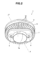
- FIG. 2 is a perspective view of an external configuration of the light source unit shown in FIG. 1 viewed from a thermal radiating section side.
- FIG. 3 is a perspective view of the configuration of a luminaire including a light source device, which includes the light source unit shown in FIG. 1 , and a socket.
- a luminaire 10 according to this embodiment shown in FIG. 3 includes a light source unit 1 included in the light source device according to this embodiment and a socket 11.
- the socket 11 is attached to a not-shown appliance main body such as a downlight.
- the socket 11 includes a cylindrical socket main body 12 made of synthetic resin having electrical insulation properties.
- a through-hole 12A is formed in the center of the socket body 12 to pierce through the socket main body 12 in the up/down direction.
- connection holes 14 are formed in the socket sections 13. Not-shown receptacles, to which electric power is supplied, are arranged on the inner side of the connection holes 14.
- the connection holes 14 are long holes having an arcuate shape concentric to the center of the socket main body 12. Expanded diameter sections 15 are integrally formed at one ends of the long holes.
- the light source unit 1 is detachably attached to such a socket 11. Specifically, a protrusion section 7A of a cap 7 of the light source unit 1 to be explained below is fit in the through-hole 12A of the socket 11. At the same time, electrode sections 8 of the light source unit 1 are inserted through the expanded diameter sections 15 of the socket sections 13. The light source unit 1 is rotated in a clockwise direction in FIG. 3 , whereby the electrode sections 8 of the light source unit 1 move from the expanded diameter sections 15 to the connection holes 14 while sliding. When the electrode sections 8 reach proximal ends of the connection holes 14, the electrode sections 8 are electrically connected to the not-shown receptacles and, at the same time, fixed. In this way, the light source unit 1 is attached to the socket 11.
- FIG. 4 is an exploded perspective view of the light source unit shown in FIG. 1 .
- the light source unit 1 includes a light source module 2, a main body 3, an upper lid 4, a power supply circuit case 5, a power supply circuit 6, the cap 7, the pair of electrode sections 8, and a globe 9.
- the light source module 2 is, for example, an LED module in which a light emitting surface 2a is formed by arranging plural LEDs (not shown in the figures), which function as light emitting devices, thereon.
- the LED module 2 includes the light emitting surface 2a of a chip on board (COB)) type formed by arranging plural LEDs thereon.
- COB chip on board
- the light emitting surface 2a is formed by arranging plural LEDs, which are light emitting devices, in lengthwise and crosswise directions on a substrate.
- the LED module 2 includes a substrate 2A to which the LEDs are electrically connected and a connector 2B set on the substrate 2A and configured to electrically connect a connection line from the power supply circuit 6 and the LEDs.
- the light emitting devices included in the light source module 2 are not limited to the LEDs and may be luminous bodies such as organic ELs. Either one light emitting device or plural light emitting devices may be provided.
- the light emitting surface 2a is formed by arranging the plural LEDs in the lengthwise and crosswise directions.
- the light emitting surface 2a is not limited to this.
- the light emitting surface 2a may be formed by, for example, arranging the plural LEDs in a circular shape on a substrate.
- the main body 3 is formed to have thermal conductivity by a manufacturing method such as die cast using a member such as metal.
- the main body 3 includes a setting surface section 3B on which the LED module 2 is set and thermal radiating fins 3A disposed on the rear surface of the setting surface section 3B on the outer circumferential side and radiating heat received from the LED module 2 and the power supply circuit 6.
- a wall section for fitting the globe 9 is formed at an outer circumferential edge 3X on the setting surface section 3B side of the main body 3.
- the plural thermal radiating fins 3A are disposed in the outer circumferential section of the surface on the rear side of the setting surface section 3B of the main body 3.
- the thermal radiating fins 3A form a thermal radiating section for radiating heat generated in the light source unit 1.
- the thermal radiating section is not limited to this.
- the thermal radiating section may be formed by plural needles. It goes without saying that, besides the thermal radiating fins and the needles, the thermal radiating section may be formed in any structure as long as a surface area is increased and effective thermal radiation action is obtained.
- the upper lid 4 and the cap 7 having stored therein the power supply circuit case 5, in which the power supply circuit 6 is stored, are attached.
- the power supply circuit case 5, in which the power supply circuit 6 is stored is stored in the cap 7.
- the electrode sections 8 are respectively fit in electrode section attachment holes 5a provided on both sides of the power supply circuit case 5.
- the upper lid 4 is put over the cap 7 from the upper direction in FIG. 4 .
- pins of the electrode sections 8 are inserted through slits of substantially C-shaped collars 4a, 4a of the upper lid 4.
- locking sections 8a provided in the electrode sections 8 are respectively locked to the collars 4a, 4a.
- the locking sections 8a of the electrode sections 8 are locked to the collars 4a, 4a, whereby the movement of the electrode sections 8 in the direction of the main body 3 is regulated.
- the cap 7 having stored therein the power supply circuit case 5, the pair of electrode sections 8, and the upper lid 4 in this way is arranged on the surface on the rear side of the setting surface section 3B of the main body 3. Not-shown screws are respectively inserted through plural holes 3a provided around the setting surface section 3B of the main body 3 and, at the same time, respectively screwed in plural screw holes 7a provided in the cap 7. Consequently, the cap 7 is fixed to the surface on the rear side of the setting surface section 3B of the main body 3.
- the cap 7 is formed of a synthetic resin section having electrical insulation properties and is insulated from the pair of electrode sections 8 and the power supply circuit 6.
- plural engaging grooves 3d are provided on the inner circumferential surface of the outer circumferential edge 3X on the setting surface section 3B side of the main body 3.
- An engaging section 9a of the globe 9 engages with the plural engaging grooves 3d, whereby the globe 9 can be fixed to the main body 3.
- the globe 9 is formed of a transparent or light diffusing synthetic resin material having translucency such as polycarbonate and is formed in a bottomed flat cylindrical shape.
- the light source unit 1 according to this embodiment shown in FIGS. 1 , 2 , and 4 can be assembled.
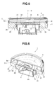
- FIG. 5 is a perspective view of a V-V line cross section of FIG. 2 for explaining the configuration of a main part of the light source unit according to this embodiment.
- FIG. 6 is a perspective view of the light source unit taken along the cross section shown in FIG. 5 .
- FIG. 7 is a perspective view of an external configuration of a main body shown in FIG. 4 viewed from the thermal radiating section side.
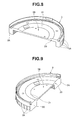
- FIG. 8 is a perspective view of a VIII-VIII line cross section shown in FIG. 7 .
- FIG. 9 is a perspective view of a IX-IX line cross section shown in FIG. 7 .
- the main body 3 includes a thick section 30 arranged between the setting surface section 3B and the thermal radiating fins 3A.
- the thick section 30 includes, in a cross section of the main body 3 in a direction along an optical axis 0 direction of the LED module 2, an inclined plane 31 that inclines from the LED module 2 toward the outer side to divert light to an irradiation direction of light of the LED module 2.
- the inclined plane 31 is formed to be thicker than the setting surface section 3B.
- An inclination angle of the inclined plane 31 is not specifically limited and only has to be an inclination angle at which light can be reflected to be diverted to the irradiation direction of the light of the LED module 2.
- the thickness of the inclined plane 31 is formed to be larger than the thickness of the setting surface section 3B. However, it is desirable to form the inclined plane 31 to have thickness at which thermal conductivity can be increased.
- white paint is applied to the surfaces of the setting surface section 3B and the inclined plane 31 of the main body 3 except a portion where the substrate 2A of the LED module 2 is arranged.
- the light from the LED module 2 is effectively reflected in the irradiation direction of the light.
- the proximal end of the cap 7 is set in contact with the surface on the opposite side of the inclined plane 31 of the thick section 30 of the main body 3.
- the proximal end of the cap 7 is provided in contact with the surface on the opposite side of the inclined plane 31 of the thick section 30 of the main body 3. Therefore, even if heat generated by the power supply circuit 6 is transferred to the cap 7, the heat transferred to the cap 7 is actively transferred to the thick section 30 of the main body 3.
- the thick section 30 including the inclined plane 31 is thicker than the setting surface section 3B. Therefore, the thick section 30 has smaller thermal resistance. Further, since the inclined plane 31 is formed, the thickness of the thick section 30 gradually increases toward the outer side. Therefore, since the thermal resistance of the thick section 30 further decreases, thermal conductivity increases. Therefore, it is possible to transfer a larger heat quantity to the thermal radiating fins 3A side. At the same time, it is possible to radiate heat transferred by the main body 3 itself and the thermal radiating fins 3A.
- part of the thermal radiating fins 3A are formed closer to at least a part of the thick section 30.
- the surface area of the thermal radiating fins 3A connected to at least the part of the thick section 30 is formed large.
- a part of the thermal radiating section of the main body 3 is formed closer to the at least the part of the thick section 30.
- the shape of a recess formed on the inner side of the plural thermal radiating fins 3A is usually formed in a substantially arcuate shape as indicated by a dotted line in FIG. 7 .
- a predetermined number of thermal radiating fins 3A arranged to be opposed to each other based on the shape of the thick section 30 are formed closer to the part of the thick section 30 by a distance L from the dotted line. Therefore, the shape of the recess formed on the inner side of the plural thermal radiating fins 3A is a track field shape.
- the thermal radiating fins 3A close to the center axis 01 expand in a direction orthogonal to the optical axis O direction of the LED module 2. Therefore, since the surface areas of the thermal radiating fins 3A increases, it is possible to further improve the thermal radiation action.
- the shape of the recess formed on the inner side of the plural thermal radiating fins 3A is not limited to the track field shape shown in FIG. 7 .
- the recess may be formed in a polygonal shape such as a rectangular shape or an arcuate shape.
- the main body 3 includes the thick section 30 thicker than the setting surface section 3B and having small thermal resistance and high thermal conductivity. Further, since the inclined plane 31 is formed, the thickness of the thick section 30 gradually increases toward the outer side.
- the thermal resistance of the thick section 30 further decreases and the thermal conductivity of the thick section 30 further increases, it is possible to transfer a larger amount of heat to the thermal radiating fins 3A side.
- the inclined plane 31 of the thick section 30 of the main body 3 inclines from the LED module 2 toward the outer side to divert the light of the LED module 2 to the irradiation direction.
- the outer circumferential edge 3X of the main body 3 is arranged on an extended line y of the inclined plane 31 or on a lower side than the extended line y.
- the light source unit 1 has structure in which a part of a light beam emitted from the LED unit 2 is not irradiated on the wall section formed at the outer circumferential edge 3X of the main body 3. Therefore, it is possible to more surely reduce a light beam loss.
- the shape of the setting surface section 3B formed on the inner side from an S portion (see FIG. 5 ) where the inclination of the inclined plane 31 starts may be used for positioning in setting the LED module 2. Consequently, it is possible to simplify assembly work in attaching the LED module 2 to the setting surface section 3B of the main body 3.
- the LED module 2 may be arranged in a position lower than the thick section 30 of the main body 3. Consequently, it is possible to more effectively lead a light beam emitted from the LED module 2 to the inclined plane 31 and more surely reduce a light beam loss.
- the light source unit 1 that can effectively radiate heat generated in the light source unit 1 to the outside of the main body 3 and reduce a loss of a light beam from the LED module 2, the light source device including the light source unit 1, and the luminaire 10 including the light source device.
Landscapes
- Engineering & Computer Science (AREA)
- General Engineering & Computer Science (AREA)
- Physics & Mathematics (AREA)
- Microelectronics & Electronic Packaging (AREA)
- Optics & Photonics (AREA)
- Non-Portable Lighting Devices Or Systems Thereof (AREA)
- Arrangement Of Elements, Cooling, Sealing, Or The Like Of Lighting Devices (AREA)
Abstract
Description
- Embodiments described herein relate generally to a light source unit including a light source module and a main body, which includes a setting surface section on which the light source module is set, a light source device including the light source unit, and a luminaire including the light source device.
- A luminaire including a light source device has been widely used. The light source device of the luminaire includes a light source unit. The light source unit usually includes a light source module, which is a light source, and a main body including a setting surface section on which the light source module is set.
- As a light source module, a light source module including a light emitting device such as an LED is effective in terms of high power and energy saving and is put to practical use.
- In such a light source unit, during lighting, the light source module and a power supply circuit for lighting the light source module generate heat. Therefore, the light source unit transfers the heat generated by the light source module and the power supply circuit to the main body formed of a thermally conductive member. The main body itself and a thermal radiating section such as thermal radiating fins formed in the main body radiate the heat.
-
-
FIG. 1 is a perspective view of an external configuration of a light source unit according to an embodiment; -
FIG. 2 is a perspective view of an external configuration of the light source unit shown inFIG. 1 viewed from a thermal radiating section side; -
FIG. 3 is a perspective view of the configuration of a luminaire including a light source device, which includes the light source unit shown inFIG. 1 , and a socket; -
FIG. 4 is an exploded perspective view of the light source unit shown inFIG. 1 ; -
FIG. 5 is a V-V line sectional view ofFIG. 2 for explaining the configuration of a main part of the light source unit; -
FIG. 6 is a perspective view of the light source unit taken along a cross section shown inFIG. 5 ; -
FIG. 7 is a perspective view of an external configuration of a main body shown inFIG. 4 viewed from the thermal radiating section side; -
FIG. 8 is a perspective view of a VIII-VIII line cross section shown inFIG. 7 ; and -
FIG. 9 is a perspective view of a IX-IX line cross section shown inFIG. 7 . - According to one embodiment, a light source unit includes: a light source module including at least one light emitting device; and a main body including: a setting surface section on which the light source module is set; a thermal radiating section disposed around the setting surface section and configured to radiate heat received from the light source module; and a thick section arranged between the setting surface section and the thermal radiating section and including an inclined plane that has thickness larger than the thickness of the setting surface section and inclines in an irradiation direction from the light source module toward the outer side.
- According to another embodiment, a light source device includes: the light source unit according to the abovementioned embodiment; a power supply circuit for lighting the light source module of the light source unit; and a cap configured to store the power supply circuit and attached to the main body.
- According to still another embodiment, a luminaire includes: the light source device according to the abovementioned embodiment; and a socket to which the cap of the light source device is detachably attached.
- With the light source unit, the light source device including the light source unit, and the luminaire including the light source device according to the embodiments, it is possible to effectively radiate heat generated in the light source unit to the outside of the main body and reduce a loss of a light beam emitted from the light source module.
- In the embodiments, definitions and technical meanings of terms are as explained below unless specifically limited.
- As at least one light emitting device included in the light source module, an LED is used. However, the light emitting device is not limited to this and may be a luminous body such as an organic EL.
- A light emitting surface formed by arranging the at least one light emitting device is formed in, for example, a chip on board (COB) type. However, the light emitting surface is not limited to this.
- When plural light emitting devices are used, the light emitting surface is formed in, for example, a square shape with the plural light emitting devices disposed thereon lengthwise and crosswise. However, the light emitting surface is not limited to this. The plural light emitting devices may be disposed in a circular shape, an elliptical shape, or the like.
- The main body is formed to have thermal conductivity by a manufacturing method such as die cast. However, the main body may be formed by any method as long as the main body has thermal conductivity. The thermal radiating section of the main body includes plural thermal radiating fins or plural needles provided in the outer circumference on the rear side of the setting surface section for the light source module. However, the thermal radiating section is not limited to this. The thermal radiating section may have any configuration as long as the configuration increases a surface area and is effective for thermal radiation action.
- The inclined plane of the main body inclines from the light source module toward the outer side to divert light of the light source module to the irradiation direction. However, an angle of the inclination is not specifically limited to this and only has to be an inclination angle at which light can be reflected to be diverted to the irradiation direction of the light of the light source module.
- The thickness of the inclined plane is formed to be larger than the thickness of the setting surface section. However, it is desirable to form the inclined plane to have thickness at which thermal conductivity can be increased.
- An embodiment is explained in detail below with reference to the accompanying drawings.
-
FIG. 1 is a perspective view of an external configuration of a light source unit according to the embodiment.FIG. 2 is a perspective view of an external configuration of the light source unit shown inFIG. 1 viewed from a thermal radiating section side.FIG. 3 is a perspective view of the configuration of a luminaire including a light source device, which includes the light source unit shown inFIG. 1 , and a socket. - First, a schematic configuration of the luminaire according to this embodiment is explained with reference to
FIG. 3 . - A
luminaire 10 according to this embodiment shown inFIG. 3 includes alight source unit 1 included in the light source device according to this embodiment and asocket 11. - The
socket 11 is attached to a not-shown appliance main body such as a downlight. Thesocket 11 includes a cylindrical socketmain body 12 made of synthetic resin having electrical insulation properties. A through-hole 12A is formed in the center of thesocket body 12 to pierce through the socketmain body 12 in the up/down direction. - A pair of
socket sections main body 12.Connection holes 14 are formed in thesocket sections 13. Not-shown receptacles, to which electric power is supplied, are arranged on the inner side of theconnection holes 14. Theconnection holes 14 are long holes having an arcuate shape concentric to the center of the socketmain body 12. Expandeddiameter sections 15 are integrally formed at one ends of the long holes. - The
light source unit 1 is detachably attached to such asocket 11. Specifically, aprotrusion section 7A of acap 7 of thelight source unit 1 to be explained below is fit in the through-hole 12A of thesocket 11. At the same time,electrode sections 8 of thelight source unit 1 are inserted through the expandeddiameter sections 15 of thesocket sections 13. Thelight source unit 1 is rotated in a clockwise direction inFIG. 3 , whereby theelectrode sections 8 of thelight source unit 1 move from the expandeddiameter sections 15 to theconnection holes 14 while sliding. When theelectrode sections 8 reach proximal ends of theconnection holes 14, theelectrode sections 8 are electrically connected to the not-shown receptacles and, at the same time, fixed. In this way, thelight source unit 1 is attached to thesocket 11. - The configuration and the assembly structure of the
light source unit 1 according to this embodiment are explained with reference toFIGS. 1 to 4 .FIG. 4 is an exploded perspective view of the light source unit shown inFIG. 1 . - As shown in
FIGS. 1 to 4 , thelight source unit 1 according to this embodiment includes alight source module 2, amain body 3, an upper lid 4, a powersupply circuit case 5, apower supply circuit 6, thecap 7, the pair ofelectrode sections 8, and aglobe 9. - The
light source module 2 is, for example, an LED module in which alight emitting surface 2a is formed by arranging plural LEDs (not shown in the figures), which function as light emitting devices, thereon. TheLED module 2 includes thelight emitting surface 2a of a chip on board (COB)) type formed by arranging plural LEDs thereon. Although not-shown in the figure, thelight emitting surface 2a is formed by arranging plural LEDs, which are light emitting devices, in lengthwise and crosswise directions on a substrate. - The
LED module 2 includes asubstrate 2A to which the LEDs are electrically connected and aconnector 2B set on thesubstrate 2A and configured to electrically connect a connection line from thepower supply circuit 6 and the LEDs. - The light emitting devices included in the
light source module 2 are not limited to the LEDs and may be luminous bodies such as organic ELs. Either one light emitting device or plural light emitting devices may be provided. - The
light emitting surface 2a is formed by arranging the plural LEDs in the lengthwise and crosswise directions. However, thelight emitting surface 2a is not limited to this. Thelight emitting surface 2a may be formed by, for example, arranging the plural LEDs in a circular shape on a substrate. - The
main body 3 is formed to have thermal conductivity by a manufacturing method such as die cast using a member such as metal. Themain body 3 includes asetting surface section 3B on which theLED module 2 is set andthermal radiating fins 3A disposed on the rear surface of the settingsurface section 3B on the outer circumferential side and radiating heat received from theLED module 2 and thepower supply circuit 6. A wall section for fitting theglobe 9 is formed at an outercircumferential edge 3X on thesetting surface section 3B side of themain body 3. - In the
setting surface section 3B of themain body 3, as shown inFIG. 4 , fourscrew holes 3b are provided. In a state in which thesubstrate 2A of theLED module 2 is placed on thesetting surface section 3B, not-shown screws are respectively screwed in thescrew holes 3b, whereby theLED module 2 is fixed on thesetting surface section 3B. A not-shown connection line connected to theconnector 2B of theLED module 2 is led to thepower supply circuit 6 disposed on the rear side of themain body 3 via aconnection hole 3c provided near the settingsurface section 3B. - As shown in
FIG. 2 , the pluralthermal radiating fins 3A are disposed in the outer circumferential section of the surface on the rear side of the settingsurface section 3B of themain body 3. Thethermal radiating fins 3A form a thermal radiating section for radiating heat generated in thelight source unit 1. However, the thermal radiating section is not limited to this. For example, the thermal radiating section may be formed by plural needles. It goes without saying that, besides the thermal radiating fins and the needles, the thermal radiating section may be formed in any structure as long as a surface area is increased and effective thermal radiation action is obtained. - On the rear side of the setting
surface section 3B of themain body 3, as shown inFIG. 4 , the upper lid 4 and thecap 7 having stored therein the powersupply circuit case 5, in which thepower supply circuit 6 is stored, are attached. - In this case, the power
supply circuit case 5, in which thepower supply circuit 6 is stored, is stored in thecap 7. Theelectrode sections 8 are respectively fit in electrodesection attachment holes 5a provided on both sides of the powersupply circuit case 5. The upper lid 4 is put over thecap 7 from the upper direction inFIG. 4 . At this point, pins of theelectrode sections 8 are inserted through slits of substantially C-shapedcollars sections 8a provided in theelectrode sections 8 are respectively locked to thecollars sections 8a of theelectrode sections 8 are locked to thecollars electrode sections 8 in the direction of themain body 3 is regulated. - The
cap 7 having stored therein the powersupply circuit case 5, the pair ofelectrode sections 8, and the upper lid 4 in this way is arranged on the surface on the rear side of the settingsurface section 3B of themain body 3. Not-shown screws are respectively inserted throughplural holes 3a provided around the settingsurface section 3B of themain body 3 and, at the same time, respectively screwed inplural screw holes 7a provided in thecap 7. Consequently, thecap 7 is fixed to the surface on the rear side of the settingsurface section 3B of themain body 3. - The
cap 7 is formed of a synthetic resin section having electrical insulation properties and is insulated from the pair ofelectrode sections 8 and thepower supply circuit 6. - On the other hand,
plural engaging grooves 3d are provided on the inner circumferential surface of the outercircumferential edge 3X on thesetting surface section 3B side of themain body 3. An engagingsection 9a of theglobe 9 engages with theplural engaging grooves 3d, whereby theglobe 9 can be fixed to themain body 3. Theglobe 9 is formed of a transparent or light diffusing synthetic resin material having translucency such as polycarbonate and is formed in a bottomed flat cylindrical shape. - In this way, the
light source unit 1 according to this embodiment shown inFIGS. 1 ,2 , and4 can be assembled. - The configuration of a main part, which is a characteristic of the
light source unit 1 according to this embodiment, is explained with reference toFIGS. 5 to 9 . -
FIG. 5 is a perspective view of a V-V line cross section ofFIG. 2 for explaining the configuration of a main part of the light source unit according to this embodiment.FIG. 6 is a perspective view of the light source unit taken along the cross section shown inFIG. 5 .FIG. 7 is a perspective view of an external configuration of a main body shown inFIG. 4 viewed from the thermal radiating section side.FIG. 8 is a perspective view of a VIII-VIII line cross section shown inFIG. 7 .FIG. 9 is a perspective view of a IX-IX line cross section shown inFIG. 7 . - As shown in
FIGS. 5 and 6 , in thelight source unit 1 according to this embodiment, themain body 3 includes athick section 30 arranged between the settingsurface section 3B and thethermal radiating fins 3A. - The
thick section 30 includes, in a cross section of themain body 3 in a direction along anoptical axis 0 direction of theLED module 2, aninclined plane 31 that inclines from theLED module 2 toward the outer side to divert light to an irradiation direction of light of theLED module 2. Theinclined plane 31 is formed to be thicker than the settingsurface section 3B. - An inclination angle of the
inclined plane 31 is not specifically limited and only has to be an inclination angle at which light can be reflected to be diverted to the irradiation direction of the light of theLED module 2. The thickness of theinclined plane 31 is formed to be larger than the thickness of the settingsurface section 3B. However, it is desirable to form theinclined plane 31 to have thickness at which thermal conductivity can be increased. - For example, white paint is applied to the surfaces of the setting
surface section 3B and theinclined plane 31 of themain body 3 except a portion where thesubstrate 2A of theLED module 2 is arranged. The light from theLED module 2 is effectively reflected in the irradiation direction of the light. - As shown in
FIG. 5 , in thelight source unit 1 according to this embodiment, the proximal end of thecap 7 is set in contact with the surface on the opposite side of theinclined plane 31 of thethick section 30 of themain body 3. The proximal end of thecap 7 is provided in contact with the surface on the opposite side of theinclined plane 31 of thethick section 30 of themain body 3. Therefore, even if heat generated by thepower supply circuit 6 is transferred to thecap 7, the heat transferred to thecap 7 is actively transferred to thethick section 30 of themain body 3. - In the
light source unit 1 according to this embodiment, thethick section 30 including theinclined plane 31 is thicker than the settingsurface section 3B. Therefore, thethick section 30 has smaller thermal resistance. Further, since theinclined plane 31 is formed, the thickness of thethick section 30 gradually increases toward the outer side. Therefore, since the thermal resistance of thethick section 30 further decreases, thermal conductivity increases. Therefore, it is possible to transfer a larger heat quantity to thethermal radiating fins 3A side. At the same time, it is possible to radiate heat transferred by themain body 3 itself and thethermal radiating fins 3A. - In the
light source unit 1 according to this embodiment, as shown inFIG. 7 , on the rear side of themain body 3 viewed from a slightly oblique direction of the optical axis O of theLED module 2, part of thethermal radiating fins 3A are formed closer to at least a part of thethick section 30. The surface area of thethermal radiating fins 3A connected to at least the part of thethick section 30 is formed large. - In other words, when viewed from the optical axis O direction of the
light source module 2, a part of the thermal radiating section of themain body 3 is formed closer to the at least the part of thethick section 30. - The shape of a recess formed on the inner side of the plural
thermal radiating fins 3A is usually formed in a substantially arcuate shape as indicated by a dotted line inFIG. 7 . However, in this embodiment, as shown inFIG. 7 , a predetermined number ofthermal radiating fins 3A arranged to be opposed to each other based on the shape of thethick section 30 are formed closer to the part of thethick section 30 by a distance L from the dotted line. Therefore, the shape of the recess formed on the inner side of the pluralthermal radiating fins 3A is a track field shape. - Therefore, compared with the
thermal radiating fins 3A not close to acenter axis 01 of the main body 3 (seeFIG. 8 ), thethermal radiating fins 3A close to thecenter axis 01 expand in a direction orthogonal to the optical axis O direction of theLED module 2. Therefore, since the surface areas of thethermal radiating fins 3A increases, it is possible to further improve the thermal radiation action. - The shape of the recess formed on the inner side of the plural
thermal radiating fins 3A is not limited to the track field shape shown inFIG. 7 . For example, the recess may be formed in a polygonal shape such as a rectangular shape or an arcuate shape. - The action of the
light source unit 1 according to this embodiment is explained with reference toFIGS. 5 to 9 . - In the
light source unit 1 according to this embodiment, themain body 3 includes thethick section 30 thicker than the settingsurface section 3B and having small thermal resistance and high thermal conductivity. Further, since theinclined plane 31 is formed, the thickness of thethick section 30 gradually increases toward the outer side. - Therefore, since the thermal resistance of the
thick section 30 further decreases and the thermal conductivity of thethick section 30 further increases, it is possible to transfer a larger amount of heat to thethermal radiating fins 3A side. - Therefore, even if the heat from the
LED module 2 and the heat from thecap 7 join in thethick section 30 of themain body 3, since the thermal resistance of thethick section 30 of themain body 3 is small, it is possible to absorb a large amount of heat and radiate the heat in themain body 3 itself. At the same time, it is possible to transfer a larger amount of heat to thethermal radiating fins 3A side and radiate the heat to the outside of themain body 3 using thethermal radiating fins 3A. - At this point, it is possible to further improve the thermal radiation effect using the plural
thermal radiating fins 3A formed closer to thecenter axis 01 of themain body 3 and having the large surface area as shown inFIG. 7 . - Further, in the
light source unit 1 according to this embodiment, theinclined plane 31 of thethick section 30 of themain body 3 inclines from theLED module 2 toward the outer side to divert the light of theLED module 2 to the irradiation direction. - Therefore, in the cross section of the
main body 3 along the optical axis O direction of theLED module 2, even if the wall section formed at the outercircumferential edge 3X on thesetting surface section 3B side of themain body 3 of theLED module 2 is arranged in a position higher than theLED module 2 arranged in thesetting surface section 3B, it is possible to reflect, using theinclined plane 31, a part of a light beam emitted from theLED module 2 to be diverted to the irradiation direction of the light of theLED module 2. Consequently, it is possible to reduce a light beam loss of the light source device. - In the
light source unit 1 according to this embodiment, as shown inFIG. 5 , in the cross section of themain body 3 in the direction along the optical axis O direction of theLED module 2, the outercircumferential edge 3X of themain body 3 is arranged on an extended line y of theinclined plane 31 or on a lower side than the extended line y. In other words, in the first place, thelight source unit 1 has structure in which a part of a light beam emitted from theLED unit 2 is not irradiated on the wall section formed at the outercircumferential edge 3X of themain body 3. Therefore, it is possible to more surely reduce a light beam loss. - In the
light source unit 1 according to this embodiment, as shown inFIG. 4 , on the plane of themain body 3 viewed from the optical axis O direction of theLED module 2, the shape of the settingsurface section 3B formed on the inner side from an S portion (seeFIG. 5 ) where the inclination of theinclined plane 31 starts may be used for positioning in setting theLED module 2. Consequently, it is possible to simplify assembly work in attaching theLED module 2 to thesetting surface section 3B of themain body 3. - Further, as shown in
FIG. 5 , in the cross section of themain body 3 in the direction along the optical axis O direction of theLED module 2, theLED module 2 may be arranged in a position lower than thethick section 30 of themain body 3. Consequently, it is possible to more effectively lead a light beam emitted from theLED module 2 to theinclined plane 31 and more surely reduce a light beam loss. - Therefore, according to this embodiment, it is possible to realize the
light source unit 1 that can effectively radiate heat generated in thelight source unit 1 to the outside of themain body 3 and reduce a loss of a light beam from theLED module 2, the light source device including thelight source unit 1, and theluminaire 10 including the light source device. - While certain embodiments have been described, these embodiments have been presented by way of example only, and are not intended to limit the scope of the inventions. Indeed, the novel embodiments described herein may be embodied in a variety of other forms; furthermore, various omissions, substitutions and changes in the form of the embodiments described herein may be made without departing from the spirit of the inventions. The accompanying claims and their equivalents are intended to cover such forms or modifications as would fall within the scope and spirit of the inventions.
Claims (10)
- A light source unit (1) comprising:a light source module (2) including at least one light emitting device; anda main body (3), whereinthe main body (3) includes:a setting surface section (3B) on which the light source module is set;a thermal radiating section (3A) disposed around the setting surface section and configured to radiate heat received from the light source module; anda thick section (30) arranged between the setting surface section and the thermal radiating section and including an inclined plane (31) that has thickness larger than thickness of the setting surface section and inclines in an irradiation direction from the light source module toward an outer side.
- The unit according to claim 1, wherein, when viewed from an optical axis direction of the light source module, a part of the thermal radiating section of the main body is formed closer to at least a part of the thick section.
- The unit according to claim 1 or 2, wherein, in a cross section of the main body in a direction along an optical axis direction of the light source module, an outer circumferential edge (3X) of the main body is arranged on an extended line of the inclined plane (31) or on a lower side than the extended line.
- The unit according to claim 1, 2, or 3, wherein, on a plane on the setting surface section side of the main body viewed from an optical axis direction of the light source module, a shape of the setting surface section formed on an inner side from a portion where inclination of the inclined plane starts is used for positioning in setting the light source module.
- The unit according to any one of claims 1 to 4, wherein, in a cross section of the main body in a direction along an optical axis direction of the light source module, the light source module is arranged in a position lower than the thick section of the main body.
- The unit according to any one of claims 1 to 5, wherein paint that reflects light from the light source module (2) is applied to the inclined plane (31).
- The unit according to any one of claims 1 to 6, wherein an inclination angle of the inclined plane (31) is an angle at which light can be reflected to be diverted to an irradiation direction of light of the light source module (2).
- A light source device comprising:the light source unit (1) according to any one of claims 1 to 7;a power supply circuit (6) for lighting the light source module of the light source unit (1); anda cap (7) configured to store the power supply circuit and attached to the main body.
- The device according to claim 8, wherein a proximal end of the cap (7) is provided in contact with a surface on an opposite side of the inclined plane (31) of the thick section (30) of the main body (3).
- A luminaire comprising:the light source device (1) according to claim 8 or 9; anda socket (11) to which the cap of the light source device is detachably attached.
Applications Claiming Priority (1)
| Application Number | Priority Date | Filing Date | Title |
|---|---|---|---|
| JP2011209925A JP5724789B2 (en) | 2011-09-26 | 2011-09-26 | LIGHT SOURCE UNIT, LIGHT SOURCE DEVICE, AND LIGHTING APPARATUS USING THE LIGHT SOURCE DEVICE |
Publications (2)
| Publication Number | Publication Date |
|---|---|
| EP2573460A2 true EP2573460A2 (en) | 2013-03-27 |
| EP2573460A3 EP2573460A3 (en) | 2014-08-06 |
Family
ID=46679165
Family Applications (1)
| Application Number | Title | Priority Date | Filing Date |
|---|---|---|---|
| EP12179044.8A Withdrawn EP2573460A3 (en) | 2011-09-26 | 2012-08-02 | Light source unit, light source device including light source unit, and luminaire including light source device |
Country Status (4)
| Country | Link |
|---|---|
| US (1) | US20130077301A1 (en) |
| EP (1) | EP2573460A3 (en) |
| JP (1) | JP5724789B2 (en) |
| CN (1) | CN203010229U (en) |
Families Citing this family (2)
| Publication number | Priority date | Publication date | Assignee | Title |
|---|---|---|---|---|
| CN103244932A (en) * | 2013-05-29 | 2013-08-14 | 江苏文光车辆附件有限公司 | External heat dissipation mechanism for LED front steering lamp |
| JP7313524B2 (en) * | 2017-08-09 | 2023-07-24 | 三菱電機株式会社 | lighting equipment |
Family Cites Families (14)
| Publication number | Priority date | Publication date | Assignee | Title |
|---|---|---|---|---|
| JP4486535B2 (en) * | 2005-03-18 | 2010-06-23 | 小泉産業株式会社 | Illumination device and multi-point light source unit |
| US20060274529A1 (en) * | 2005-06-01 | 2006-12-07 | Cao Group, Inc. | LED light bulb |
| TW200847467A (en) * | 2007-05-23 | 2008-12-01 | Tysun Inc | Light emitting diode lamp |
| US7874699B2 (en) * | 2007-07-05 | 2011-01-25 | Aeon Lighting Technology Inc. | Heat dissipating device for LED light-emitting module |
| US7670021B2 (en) * | 2007-09-27 | 2010-03-02 | Enertron, Inc. | Method and apparatus for thermally effective trim for light fixture |
| GB2453718A (en) * | 2007-10-10 | 2009-04-22 | Unity Opto Technology Co Ltd | LED lighting device |
| KR101253821B1 (en) * | 2007-12-07 | 2013-04-12 | 오스람 게엠베하 | Lighting device including heat sink and heat sink |
| EP2154419B1 (en) * | 2008-07-31 | 2016-07-06 | Toshiba Lighting & Technology Corporation | Self-ballasted lamp |
| EP2530378B1 (en) * | 2009-02-04 | 2015-09-23 | Panasonic Intellectual Property Management Co., Ltd. | Bulb-shaped lamp and lighting device |
| US8602579B2 (en) * | 2009-09-25 | 2013-12-10 | Cree, Inc. | Lighting devices including thermally conductive housings and related structures |
| WO2011050256A1 (en) * | 2009-10-22 | 2011-04-28 | Thermal Solution Resources, Llc | Overmolded led light assembly and method of manufacture |
| US9435493B2 (en) * | 2009-10-27 | 2016-09-06 | Cree, Inc. | Hybrid reflector system for lighting device |
| US9316361B2 (en) * | 2010-03-03 | 2016-04-19 | Cree, Inc. | LED lamp with remote phosphor and diffuser configuration |
| KR101285889B1 (en) * | 2010-06-23 | 2013-07-11 | 엘지전자 주식회사 | LED lighting fixtures |
-
2011
- 2011-09-26 JP JP2011209925A patent/JP5724789B2/en active Active
-
2012
- 2012-08-01 US US13/564,389 patent/US20130077301A1/en not_active Abandoned
- 2012-08-02 EP EP12179044.8A patent/EP2573460A3/en not_active Withdrawn
- 2012-08-31 CN CN2012204424004U patent/CN203010229U/en not_active Expired - Lifetime
Non-Patent Citations (1)
| Title |
|---|
| None |
Also Published As
| Publication number | Publication date |
|---|---|
| CN203010229U (en) | 2013-06-19 |
| EP2573460A3 (en) | 2014-08-06 |
| US20130077301A1 (en) | 2013-03-28 |
| JP2013073696A (en) | 2013-04-22 |
| JP5724789B2 (en) | 2015-05-27 |
Similar Documents
| Publication | Publication Date | Title |
|---|---|---|
| CN104969001B (en) | Flat lighting apparatus | |
| KR200467186Y1 (en) | Led illumination device | |
| US8556462B2 (en) | LED lighting device | |
| US10295123B2 (en) | Bulb apparatus and manufacturing method thereof | |
| US9989194B2 (en) | Lighting device | |
| EP2923148B1 (en) | Lighting device comprising an improved heat transferring arrangement | |
| EP2662620A1 (en) | Bulb-shaped lamp and luminaire | |
| JP3185445U (en) | LED lamp with adjustable angle | |
| EP2811217B1 (en) | Illumination apparatus | |
| JP2012059636A (en) | Lighting system | |
| JP3163443U (en) | LED lighting device | |
| EP2573460A2 (en) | Light source unit, light source device including light source unit, and luminaire including light source device | |
| US20150241033A1 (en) | Lamp Apparatus and Luminaire | |
| KR20120060447A (en) | Led lamp with omnidirectional light distribution | |
| US9279548B1 (en) | Light collimating assembly with dual horns | |
| KR101244855B1 (en) | LED lamp | |
| JP2014132584A (en) | Illumination device | |
| JP2014179185A (en) | Lamp with base | |
| JP2013110198A (en) | Light emitting diode lamp | |
| US10184653B2 (en) | Retrofit light bulb | |
| KR20150131819A (en) | Led lamp having heat radiating housing | |
| JP2018120776A (en) | Bulb type lighting device | |
| JP2017130397A (en) | Light bulb type luminaire |
Legal Events
| Date | Code | Title | Description |
|---|---|---|---|
| PUAI | Public reference made under article 153(3) epc to a published international application that has entered the european phase |
Free format text: ORIGINAL CODE: 0009012 |
|
| AK | Designated contracting states |
Kind code of ref document: A2 Designated state(s): AL AT BE BG CH CY CZ DE DK EE ES FI FR GB GR HR HU IE IS IT LI LT LU LV MC MK MT NL NO PL PT RO RS SE SI SK SM TR |
|
| AX | Request for extension of the european patent |
Extension state: BA ME |
|
| PUAL | Search report despatched |
Free format text: ORIGINAL CODE: 0009013 |
|
| AK | Designated contracting states |
Kind code of ref document: A3 Designated state(s): AL AT BE BG CH CY CZ DE DK EE ES FI FR GB GR HR HU IE IS IT LI LT LU LV MC MK MT NL NO PL PT RO RS SE SI SK SM TR |
|
| AX | Request for extension of the european patent |
Extension state: BA ME |
|
| RIC1 | Information provided on ipc code assigned before grant |
Ipc: F21K 99/00 20100101ALI20140701BHEP Ipc: F21Y 101/02 20060101ALN20140701BHEP Ipc: F21V 29/00 20060101AFI20140701BHEP |
|
| STAA | Information on the status of an ep patent application or granted ep patent |
Free format text: STATUS: THE APPLICATION IS DEEMED TO BE WITHDRAWN |
|
| 18D | Application deemed to be withdrawn |
Effective date: 20150207 |