EP2573369A2 - Apparatus and method for controlling a drive force - Google Patents
Apparatus and method for controlling a drive force Download PDFInfo
- Publication number
- EP2573369A2 EP2573369A2 EP12006603A EP12006603A EP2573369A2 EP 2573369 A2 EP2573369 A2 EP 2573369A2 EP 12006603 A EP12006603 A EP 12006603A EP 12006603 A EP12006603 A EP 12006603A EP 2573369 A2 EP2573369 A2 EP 2573369A2
- Authority
- EP
- European Patent Office
- Prior art keywords
- abnormality
- control apparatus
- drive force
- force control
- primary
- Prior art date
- Legal status (The legal status is an assumption and is not a legal conclusion. Google has not performed a legal analysis and makes no representation as to the accuracy of the status listed.)
- Granted
Links
Images


Classifications
-
- F—MECHANICAL ENGINEERING; LIGHTING; HEATING; WEAPONS; BLASTING
- F02—COMBUSTION ENGINES; HOT-GAS OR COMBUSTION-PRODUCT ENGINE PLANTS
- F02D—CONTROLLING COMBUSTION ENGINES
- F02D41/00—Electrical control of supply of combustible mixture or its constituents
- F02D41/02—Circuit arrangements for generating control signals
- F02D41/14—Introducing closed-loop corrections
- F02D41/1497—With detection of the mechanical response of the engine
-
- F—MECHANICAL ENGINEERING; LIGHTING; HEATING; WEAPONS; BLASTING
- F02—COMBUSTION ENGINES; HOT-GAS OR COMBUSTION-PRODUCT ENGINE PLANTS
- F02D—CONTROLLING COMBUSTION ENGINES
- F02D41/00—Electrical control of supply of combustible mixture or its constituents
- F02D41/22—Safety or indicating devices for abnormal conditions
-
- F—MECHANICAL ENGINEERING; LIGHTING; HEATING; WEAPONS; BLASTING
- F02—COMBUSTION ENGINES; HOT-GAS OR COMBUSTION-PRODUCT ENGINE PLANTS
- F02D—CONTROLLING COMBUSTION ENGINES
- F02D41/00—Electrical control of supply of combustible mixture or its constituents
- F02D41/24—Electrical control of supply of combustible mixture or its constituents characterised by the use of digital means
- F02D41/26—Electrical control of supply of combustible mixture or its constituents characterised by the use of digital means using computer, e.g. microprocessor
- F02D41/266—Electrical control of supply of combustible mixture or its constituents characterised by the use of digital means using computer, e.g. microprocessor the computer being backed-up or assisted by another circuit, e.g. analogue
-
- Y—GENERAL TAGGING OF NEW TECHNOLOGICAL DEVELOPMENTS; GENERAL TAGGING OF CROSS-SECTIONAL TECHNOLOGIES SPANNING OVER SEVERAL SECTIONS OF THE IPC; TECHNICAL SUBJECTS COVERED BY FORMER USPC CROSS-REFERENCE ART COLLECTIONS [XRACs] AND DIGESTS
- Y10—TECHNICAL SUBJECTS COVERED BY FORMER USPC
- Y10S—TECHNICAL SUBJECTS COVERED BY FORMER USPC CROSS-REFERENCE ART COLLECTIONS [XRACs] AND DIGESTS
- Y10S477/00—Interrelated power delivery controls, including engine control
- Y10S477/906—Means detecting or ameliorating the effects of malfunction or potential malfunction
Definitions
- the present invention relates to a drive force control apparatus for controlling a drive force by a drive source of an engine or the like, and its control method, particularly relates to a drive force control apparatus of a riding type vehicle having a function for detecting an abnormality of the drive force control apparatus, and its control method.
- An electronic throttle valve controls an opening degree of a throttle valve by an electronic control to control an intake amount of an engine (internal combustion engine) and therefore, can realize low emission gas, low fuel cost, and is started to be adopted already in portions of passenger vehicles.
- the electronic throttle valve is provided with a function for cutting to drive the throttle valve by an electronic motor when some abnormality is brought about in a control system to return the throttle valve in a fully closing direction by an urge force of a spring (refer to, for example, Patent Reference 2 or the like).
- Patent Reference 3 describes a technology in which when an abnormality of a throttle sensor is detected, a control amount of a throttle opening degree is set to a predetermined value (tentative abnormality control), and a throttle control is stopped when the abnormality of the sensor is continued to be detected even after a determination delay time period has elapsed.
- the determination delay time until stopping the throttle control after detecting the abnormality of the sensor and therefore, an abnormality detection due to an instantaneous abnormal signal by noise or the like can be excluded, further, an amount of controlling the throttle opening degree can be fixed to a predetermined amount during the determination delay time, and therefore, control of the throttle valve based on the instantaneous abnormal output of the throttle sensor can be avoided.
- the invention has been carried out in view of such a point and it is an object thereof to provide a drive force control apparatus for a riding type vehicle (motorcycle) capable of restraining a change in a behavior of a vehicle by noise or the like.
- an apparatus for controlling a drive force generated by a drive source of a riding type vehicle comprising means for detecting an abnormality of the drive force control apparatus configured to detect the abnormality of the drive force control apparatus at a predetermined abnormality detecting period, wherein, when the abnormality of the drive force control apparatus is detected, a primary abnormality processing of the drive force control apparatus is executed, wherein, when the abnormality is not detected, the primary abnormality processing is released, and a normal electronic control of the drive force control apparatus is executed, and wherein, when an abnormality detecting signal detected by the abnormality detecting portion continues even after an elapse of a predetermined abnormality determining time period, the primary abnormality processing is shifted to a secondary abnormality processing.
- the means for detecting an abnormality repeatedly detects the abnormality of the drive force control apparatus at the predetermined abnormality detecting period, wherein, when the abnormality is detected in the drive force control apparatus, a fail signal is outputted to a primary abnormality processing portion, and by receiving the signal, the primary abnormality processing portion executes the primary abnormality processing, and wherein, when the abnormality is not detected in the drive force control apparatus, the normal electronic control of the drive force control apparatus is executed.
- the primary abnormality processing is released when an abnormality is not detected at a succeeding period, and the normal electronic control period is executed.
- the abnormality of the drive force control apparatus is repeatedly detected by the means for detecting an abnormality at the predetermined abnormality detecting period.
- the predetermined abnormality detecting period is equal to or smaller than 1/20 of the predetermined abnormality determining time period.
- the drive source is an engine, a motor, or a transmission.
- the primary abnormality processing and secondary abnormality processing may include the same execution.
- the primary abnormality processing and secondary abnormality processing might be executed by cutting to drive a throttle valve by a reduction in the fuel injection amount, and/or by a delay in the ignition time.
- a control method of a drive force control apparatus for a riding type vehicle for controlling a drive force by a drive source mounted to the vehicle, the control method comprising the steps of: detecting an abnormality of the drive force control apparatus by a predetermined abnormality detecting period; executing a primary abnormality processing of the drive force control apparatus when the abnormality of the drive force control apparatus is detected; releasing the primary abnormality processing and executing a normal control of the drive force control apparatus when the abnormality is not detected; and shifting the primary abnormality processing to a secondary abnormality processing when a detected abnormality detecting signal continues even after a predetermined abnormality determining time period.
- the drive source is an engine, a motor, or a transmission.
- a drive source mounted to a vehicle includes an engine, a motor, a transmission or the like, according to the embodiment, an explanation will be given of an engine as follows as a representative example thereof.
- Fig. 1 is a block diagram showing a basic constitution of an engine control apparatus 10 for a motorcycle according to an embodiment.
- the engine control apparatus 10 includes a control CPU (Center Processing Unit) 11 for controlling injection and ignition of the engine and controlling a throttle valve, and an abnormality detecting portion 12 for detecting an abnormality of the engine control apparatus 10.
- a control CPU Center Processing Unit
- an abnormality detecting portion 12 for detecting an abnormality of the engine control apparatus 10.
- the control CPU 11 is inputted with sensor signals of a throttle position sensor 21, an accelerator position sensor 22, an engine rotational number sensor 23, a speed sensor 24, and a water temperature sensor 25 or the like, calculates a fuel injection amount, an ignition timing, an opening degree of a throttle valve and the like necessary for controlling the engine and outputs control signals thereof.
- the control signals are respectively inputted to a drive circuit 16 for controlling a drive motor 31 of a throttle valve (not illustrated), and a drive circuit 17 for driving a fuel injection valve 32, and an ignition plug 33 to execute a predetermined electronic control.
- the abnormality detecting portion 12 repeatedly detects an abnormality of the engine control apparatus 10 at a predetermined abnormality detecting period (for example, a period of 1 ms). Further, when the abnormality is detected in the engine control apparatus 10, a fail signal is outputted to a primary abnormality processing portion 14, and by receiving the signal, the primary abnormality processing portion 14 executes to cut to drive the throttle valve (primary abnormality processing). Further, when an abnormality is not detected in the engine control apparatus 10, an electronic control at normal time of the engine control apparatus 10 is executed.
- a predetermined abnormality detecting period for example, a period of 1 ms.
- the primary abnormality processing is released when an abnormality is not detected at a succeeding period, and the electronic control at normal time is executed, however, the control is switched by a short period of about 1 ms and therefore, a rider does not feel a change in a behavior of the vehicle.
- cutting to drive the throttle valve is pointed out as an example, other processing, for example, a processing of a reduction in the fuel injection amount, a delay in the ignition time or the like may be executed.
- the abnormality detecting signal detected by the abnormality detecting portion 12 is continued even after an elapse of a predetermined abnormality determining time period (for example, 20ms), it is determined that the abnormality is brought about in the engine control apparatus 10, the primary abnormality processing which has been executed is shifted to a secondary abnormality processing.
- a predetermined abnormality determining time period for example, 20ms
- the secondary abnormality processing corresponds to an inherent processing when an abnormality is brought about and is executed by cutting to drive the throttle valve or the like. Further, when the throttle valve is executed to be cut to drive as the primary abnormality processing, successively, the processing is continued.
- a determination whether the abnormality detecting signal continues even after an elapse of the predetermined abnormality determining time period can be carried out by counting an abnormality detecting signal from the abnormality detecting portion 12 by a counter 13.
- an abnormality detection executed by the abnormality detecting portion 12 can include also an abnormality of other than the engine control apparatus 10, for example, the drive motor 31 of the throttle valve, the fuel injection valve 32, the ignition plug 33 or the like as an object thereof other than respective parts of CPU or the like constituting the engine control apparatus 10, respective sensor signals (including also disconnection, shortcircuit and the like of a wiring).
- an abnormality detecting period for detecting the abnormality of the engine control apparatus 10 and the abnormality determining time period for determining whether the inherent abnormality is brought about are not particularly limited, it is preferable that the abnormality detecting period is a short period to a degree by which a change in the vehicle behavior is not felt even when there is brought about switch to the primary abnormality processing, further, the abnormality determining time period is set to a long period to a degree by which a detection by noise or the like can be excluded. For example, it is preferable that the abnormality detecting period is equal to or smaller than 1/20 of the abnormality determining time period.
- the constitution of the engine control apparatus 10 according to the invention is not necessarily limited to a hardware constitution shown in Fig. 1 .
- the primary abnormality processing portion 14 and the secondary abnormality processing portion 15 are constituted separately from the control CPU 11, operation thereof may be executed by a predetermined program at inside of the control CPU 11.
- the abnormality detecting portion 12 is constructed by an independent constitution, the control of the abnormality detection may be carried out at inside of the control CPU 11.
- the abnormality of the engine control apparatus is detected by the predetermined abnormality detecting period, when the abnormality is detected, the primary abnormality processing is executed, when the abnormality is not detected, the primary abnormality processing is released, the electronic control at normal time is executed and therefore, the abnormality detection by noise or the like can be excluded. Further, when the abnormality detecting signal is continued even after the elapse of the predetermined abnormality determining time period, the primary abnormality processing is shifted to the secondary abnormality processing and therefore, the control of the engine control apparatus based on the abnormal output can also be avoided. Thereby, a change in the behavior of the vehicle is restrained and reliability of the engine control apparatus can be promoted.
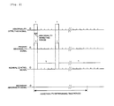
- Fig. 2 and Fig. 3 are diagrams showing an example of an abnormality detecting signal, a primary abnormality signal, a normal (at normal time) control signal, and a secondary abnormality signal according to the embodiment.
- the abnormality of the engine control apparatus 10 is repeatedly detected by the abnormality detecting portion 12 by the predetermined abnormality detecting period (for example, a period of 1ms), when the abnormality is detected, the primary abnormality determining signal (fail signal) is outputted.
- the primary abnormality processing portion 14 outputs the primary abnormality signal, and based on the signal, the primary abnormality processing (for example, cutting to drive the throttle valve) is executed.
- the normal (at normal time) control signal is outputted, and by receiving the signal by the control CPU 11, the electronic control at normal time of the engine control apparatus 10 is executed.
- either of the primary abnormality signal or the normal control signal is outputted, and by the signals, either of the primary abnormality processing or the normal (at normal time) electronic control is executed in the engine control apparatus 10.
- the abnormality detecting signal is not continued even after the elapse of the predetermined abnormality determining time period (for example, 20ms) and therefore, it is determined that the abnormality is not brought about in the engine control apparatus 10, the secondary abnormality signal is not outputted, and the secondary abnormality processing is not executed.
- the predetermined abnormality determining time period for example, 20ms
- the abnormality detecting signal is continued even after the elapse of the predetermined abnormality determining time period and therefore, it is determined that the abnormality is brought about in the engine control apparatus 10, after the elapse of the abnormality determining time period, the secondary abnormality signal is outputted, as a result, the secondary abnormality processing is executed in the engine control apparatus 10.
- Fig. 4 shows a flowchart of the embodiment.
- the engine control apparatus 10 executing the normal control (step S101)
- the primary abnormality processing is executed (step S103).
- the primary abnormality signal (FA1) is set to '1' signifying the abnormality.
- the abnormality detecting signal (FA1) is counted by the counter 13, it is determined whether a predetermined count number (for example, 20 or more) is reached (step S106), when the predetermined count number is reached, the secondary abnormality processing is executed (S107). Further, when the predetermined count number is not reached, the operation returns to S102 to determine presence or absence of abnormality detection.
- a predetermined count number for example, 20 or more
- the routine of steps S101 through S106 is repeatedly executed by the abnormality detecting period (for example, a period of 1 ms) and therefore, that FA1 counted at step S106 reaches the predetermined count number signifies that the abnormality detecting signal is continued even after the elapse of the predetermined abnormality determining time period (for example, 20ms). Therefore, in this case, it is determined that the abnormality is brought about in the engine control apparatus 10 and the secondary abnormality processing is executed in the engine control apparatus 10.
- the abnormality detecting period for example, a period of 1 ms
- an abnormality detection by noise or the like can be excluded, further, even when the abnormality is determined finally while avoiding the control of the engine control apparatus by the abnormal output, the change in the behavior of the vehicle is restrained and the reliability of the engine control apparatus can be promoted.
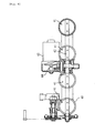
- Fig. 5 is a view showing a constitution of an electronic throttle mechanism mounted to a motorcycle.
- a throttle body 40 is constituted by a cylindrical shape, a throttle valve 41 is fixed to one piece of common valve shaft 42 arranged to penetrate all of the throttle bodies 40.
- a drive motor 43 is arranged such that a rotating shaft thereof becomes in parallel with the valve shaft 42 and the valve shaft 42 is constituted to be driven to rotate by way of a plurality of gears 44 in rotating the drive motor 43.
- Fig. 6 is a view showing a constitution of a motorcycle 200 mounted with the engine control apparatus 10 for the motorcycle according to the embodiment.
- a fuel tank 202 is provided above a tank rail 201 and an engine unit 203 is arranged therebelow.
- An engine unit 203 is functioned as a power source of water cooling type 4 cycle parallel 4 cylinders and the engine control apparatus (not illustrated) is mounted below a seat 205.
- an automatic two-wheel according to the embodiment signifies the motorcycle, includes a bicycle with prime mover (motorbike), scooter, specifically refers to a vehicle turnable by inclining a vehicle body. Therefore, the 'motorcycle' can include a three-wheel vehicle, a four-wheel vehicle (or, more wheel vehicle) by counting a number of tires by constituting at least one of a front wheel and a rear wheel by two wheels or more wheels.
- teaching is applicable not only to the motorcycle but also to other vehicle capable of utilizing the effect of the teaching, for example, the teaching is applicable to a so-to-speak riding type vehicle including a four-wheel buggy (ATV: All Terrain Vehicle) and a snow mobile other than the motor cycle.
- ATV All Terrain Vehicle
- an engine, a motor, a transmission or the like in drive sources mounted to a vehicle an apparatus controlled in a path for transmitting a drive force, for example, a clutch or the like is also included therein.
- the drive force control apparatus for the riding vehicle having the function capable of restraining the change in the behavior of the vehicle by noise or the like.
- a drive force control apparatus for a riding type vehicle characterized by including a drive source, and an abnormality detecting portion for detecting an abnormality of the drive force control apparatus for controlling a drive force by the drive source, wherein the abnormality detecting portion detects the abnormality of the drive force control apparatus by a predetermined abnormality detecting period, when the abnormality of the drive force control apparatus is detected by the abnormality detecting portion, a primary abnormality processing of the drive force control apparatus is executed, when the abnormality is not detected, the primary abnormality processing is released, an electronic control at normal time of the drive force control apparatus is executed, and when an abnormality detecting signal detected by the abnormality detecting portion continues even after an elapse of a predetermined abnormality determining time period, the primary abnormality processing is shifted to an secondary abnormality processing.
- the predetermined abnormality detecting period is equal to or smaller than 1/20 of the predetermined abnormality determining time period.
- the drive source is an engine, a motor, or a transmission.
- the primary abnormality processing includes a processing the same as the secondary abnormality processing.
- an embodiment of a control method of a drive force control apparatus for a riding type vehicle being a control method of a drive force control apparatus for a riding type vehicle for controlling a drive force by a drive source mounted to a vehicle
- the embodiment of the control method being characterized by comprising the steps of detecting an abnormality of the drive force control apparatus by a predetermined abnormality detecting period, executing a primary abnormality processing of the drive force control apparatus when the abnormality of the drive force control apparatus is detected, releasing the primary abnormality processing and executing a control at normal time of the drive force control apparatus when the abnormality is not detected, and shifting the primary abnormality processing to an secondary abnormality processing when a detected abnormality detecting signal continues even after a predetermined abnormality determining time period.
- the drive source is an engine, a motor, or a transmission.
- a riding type vehicle being characterized in being mounted with the drive force control apparatus for a riding type vehicle.
- abnormality of the drive force control apparatus is detected by the predetermined abnormality detecting period, when the abnormality is detected, the primary abnormality processing is executed, when the abnormality is not detected, the primary abnormality processing is released, the control at normal time is executed and therefore, abnormality detection by noise or the like can be excluded. Further, when the abnormality detecting signal continues even after elapse of the predetermined abnormality determining time period, the primary abnormality processing is shifted to the secondary abnormality processing and therefore, the control of the engine control apparatus based on the abnormal output can also be avoided. Thereby, a change in a behavior of the vehicle is restrained, and reliability of the engine control apparatus can be promoted.
- a drive force control apparatus for a riding type vehicle characterized by including: a drive source; and an abnormality detecting portion for detecting an abnormality of the drive force control apparatus for controlling a drive force by the drive source; wherein the abnormality detecting portion detects the abnormality of the drive force control apparatus by a predetermined abnormality detecting period: wherein when the abnormality of the drive force control apparatus is detected by the abnormality detecting portion, a primary abnormality processing of the drive force control apparatus is executed, when the abnormality is not detected, the primary abnormality processing is released, an electronic control at normal time of the drive force control apparatus is executed; and wherein when an abnormality detecting signal detected by the abnormality detecting portion continues even after an elapse of a predetermined abnormality determining time period, the primary abnormality processing is shifted to an secondary abnormality processing.
- the predetermined abnormality detecting period is equal to or smaller than 1/20 of the predetermined abnormality determining time period.
- the drive source is an engine, a motor, or a transmission.
- the primary abnormality processing includes a processing the same as the secondary abnormality processing.
- a control method of a drive force control apparatus for a riding type vehicle for controlling a drive force by a drive source mounted to a vehicle
- the preferred control method being characterized by comprising the steps of: detecting an abnormality of the drive force control apparatus by a predetermined abnormality detecting period; executing a primary abnormality processing of the drive force control apparatus when the abnormality of the drive force control apparatus is detected, releasing the primary abnormality processing and executing a control at normal time of the drive force control apparatus when the abnormality is not detected; and shifting the primary abnormality processing to an secondary abnormality processing when a detected abnormality detecting signal continues even after a predetermined abnormality determining time period.
- the drive source is an engine, a motor, or a transmission.
- the description further discloses, according to a preferred seventh aspect, a riding type vehicle mounted with the drive force control apparatus for a riding type vehicle according to any one of the preferred first to fourth aspects.
- a preferred embodiment of a drive force control apparatus for a motorcycle including a control CPU 11 for executing an electronic control of injection and ignition of a fuel and a throttle valve, and an abnormality detecting portion 12 for detecting an abnormality of the engine control apparatus 10, in which the abnormality detecting portion 12 detects the abnormality of the engine control apparatus 10 by a predetermined abnormality detecting period, when the abnormality is detected, a primary abnormality processing of the engine control apparatus 10 is executed, when the abnormality is not detected, the primary abnormality processing is released, an electronic control at normal time of the engine control apparatus 10 is executed, and when an abnormality detecting signal detected by the abnormality detecting portion 12 continues even after an elapse of a predetermined abnormality determining time period, the primary abnormality processing is shifted to an secondary abnormality processing.
Landscapes
- Engineering & Computer Science (AREA)
- General Engineering & Computer Science (AREA)
- Chemical & Material Sciences (AREA)
- Combustion & Propulsion (AREA)
- Mechanical Engineering (AREA)
- Computer Hardware Design (AREA)
- Microelectronics & Electronic Packaging (AREA)
- Electrical Control Of Air Or Fuel Supplied To Internal-Combustion Engine (AREA)
- Combined Controls Of Internal Combustion Engines (AREA)
- Control Of Throttle Valves Provided In The Intake System Or In The Exhaust System (AREA)
- Electric Propulsion And Braking For Vehicles (AREA)
Abstract
Description
- The present invention relates to a drive force control apparatus for controlling a drive force by a drive source of an engine or the like, and its control method, particularly relates to a drive force control apparatus of a riding type vehicle having a function for detecting an abnormality of the drive force control apparatus, and its control method.
- An electronic throttle valve controls an opening degree of a throttle valve by an electronic control to control an intake amount of an engine (internal combustion engine) and therefore, can realize low emission gas, low fuel cost, and is started to be adopted already in portions of passenger vehicles.
- In view of the above, in adopting an electronic throttle valve in a motorcycle, a drive motor for controlling an opening degree of a throttle valve needs to be arranged compactly while avoiding interference with a fuel injection valve arranged at an intake path. Therefore, although a compact electronic throttle control apparatus mountable to a motorcycle is proposed in
Patent Reference 1 or the like, the electronic throttle control apparatus has not been adopted yet since there is a restriction inherent to such a motorcycle. - Meanwhile, the electronic throttle valve is provided with a function for cutting to drive the throttle valve by an electronic motor when some abnormality is brought about in a control system to return the throttle valve in a fully closing direction by an urge force of a spring (refer to, for example, Patent Reference 2 or the like).
- In order to execute the function, there is needed means for detecting that an abnormality is brought about in a control system of the electronic throttle valve. For example, an opening degree of the throttle valve is detected by a throttle sensor, and a signal of the throttle sensor needs to be always monitored in order to detect an abnormal output of the throttle sensor.
- Meanwhile, there is a case in which although the throttle sensor is normal, when an instantaneous abnormal signal is outputted by noise or the like, although actually, a normal state is recovered immediately, the state is determined as an abnormality.
- In order to exclude such an instantaneous abnormal signal detection, there is conceivable a method in which in determining an abnormality, a determination delay time period longer than a signal width of noise or the like is provided, when an abnormal output continues for the determination delay time period, an abnormality is determined finally.
- However, according to the method, there is a concern that even when a control system becomes truly abnormal, the control of the throttle valve based on the abnormal output is continued until elapse of the determination delay time period, particularly, when applied to a riding type vehicle, a change in a behavior of the vehicle is increased.
- As a method of resolving such a problem, Patent Reference 3 describes a technology in which when an abnormality of a throttle sensor is detected, a control amount of a throttle opening degree is set to a predetermined value (tentative abnormality control), and a throttle control is stopped when the abnormality of the sensor is continued to be detected even after a determination delay time period has elapsed.
- According to the method, there is provided the determination delay time until stopping the throttle control after detecting the abnormality of the sensor and therefore, an abnormality detection due to an instantaneous abnormal signal by noise or the like can be excluded, further, an amount of controlling the throttle opening degree can be fixed to a predetermined amount during the determination delay time, and therefore, control of the throttle valve based on the instantaneous abnormal output of the throttle sensor can be avoided.
- Patent Reference 1:
JP-A-2002-256895 - Patent Reference 2:
JP-A-2003-201866 - Patent Reference 3:
JP-A-10-238389 - Although the method described in Patent Reference 3 mentioned above is excellent in view of the fact that reliability of the electronic throttle system can be promoted, in the tentative abnormality control, the control (the control amount of the throttle opening degree is fixed to the predetermined value) different from stopping the throttle control is carried out during the determination delay time period and therefore, there is a concern of changing a behavior of a vehicle even by noise. Further, when normality is determined thereafter, the control is recovered to a normal state and therefore, there is a concern of changing a behavior of the vehicle also at that occasion.
- The invention has been carried out in view of such a point and it is an object thereof to provide a drive force control apparatus for a riding type vehicle (motorcycle) capable of restraining a change in a behavior of a vehicle by noise or the like.
- This objective is solved in an inventive manner by an apparatus for controlling a drive force generated by a drive source of a riding type vehicle, comprising means for detecting an abnormality of the drive force control apparatus configured to detect the abnormality of the drive force control apparatus at a predetermined abnormality detecting period, wherein, when the abnormality of the drive force control apparatus is detected, a primary abnormality processing of the drive force control apparatus is executed, wherein, when the abnormality is not detected, the primary abnormality processing is released, and a normal electronic control of the drive force control apparatus is executed, and wherein, when an abnormality detecting signal detected by the abnormality detecting portion continues even after an elapse of a predetermined abnormality determining time period, the primary abnormality processing is shifted to a secondary abnormality processing.
- According to a preferred embodiment, the means for detecting an abnormality repeatedly detects the abnormality of the drive force control apparatus at the predetermined abnormality detecting period, wherein, when the abnormality is detected in the drive force control apparatus, a fail signal is outputted to a primary abnormality processing portion, and by receiving the signal, the primary abnormality processing portion executes the primary abnormality processing, and wherein, when the abnormality is not detected in the drive force control apparatus, the normal electronic control of the drive force control apparatus is executed.
- According to a further preferred embodiment, when the abnormality is detected at a preceding period and the primary abnormality processing is executed, the primary abnormality processing is released when an abnormality is not detected at a succeeding period, and the normal electronic control period is executed.
- Further, preferably the abnormality of the drive force control apparatus is repeatedly detected by the means for detecting an abnormality at the predetermined abnormality detecting period.
- Yet further, preferably the predetermined abnormality detecting period is equal to or smaller than 1/20 of the predetermined abnormality determining time period.
- Still further, preferably the drive source is an engine, a motor, or a transmission.
- Furthermore, the primary abnormality processing and secondary abnormality processing may include the same execution.
- Therein, the primary abnormality processing and secondary abnormality processing might be executed by cutting to drive a throttle valve by a reduction in the fuel injection amount, and/or by a delay in the ignition time.
- The above objective is further solved in an inventive manner by a control method of a drive force control apparatus for a riding type vehicle, for controlling a drive force by a drive source mounted to the vehicle, the control method comprising the steps of: detecting an abnormality of the drive force control apparatus by a predetermined abnormality detecting period; executing a primary abnormality processing of the drive force control apparatus when the abnormality of the drive force control apparatus is detected; releasing the primary abnormality processing and executing a normal control of the drive force control apparatus when the abnormality is not detected; and shifting the primary abnormality processing to a secondary abnormality processing when a detected abnormality detecting signal continues even after a predetermined abnormality determining time period.
- Preferably, the drive source is an engine, a motor, or a transmission.
- There is further provided a riding type vehicle mounted with the drive force control apparatus for a riding type vehicle according to one of the above embodiments.
- In the following, the present invention is explained in greater detail with respect to several embodiments thereof in conjunction with the accompanying drawings, wherein:
- Fig. 1
- is a block diagram showing a basic constitution of an engine control apparatus for a motorcycle according to an embodiment,
- Fig. 2
- is a diagram showing an example of an abnormality detecting signal, a primary abnormality signal, a normal (at normal time) control signal, and a secondary abnormality signal according to the embodiment,
- Fig. 3
- is a diagram showing an example of the abnormality detecting signal, the primary abnormality signal, the normal (at normal time) control signal, and the secondary abnormality signal according to the embodiment,
- Fig. 4
- shows a flowchart of the embodiment,
- Fig. 5
- is a view showing a constitution of an electronic throttle mechanism according to the embodiment, and
- Fig. 6
- is a view showing a constitution of a motorcycle mounted with the engine control apparatus for the motorcycle.
-
- 10
- engine (drive force) control apparatus
- 11
- control CPU
- 12
- abnormality detecting portion
- 13
- counter
- 14
- primary abnormality processing portion
- 15
- secondary abnormality processing portion
- 16, 17
- drive circuits
- 21
- throttle position sensor
- 22
- accelerator position sensor
- 23
- engine rotational number sensor
- 24
- speed sensor
- 25
- water temperature sensor
- 31
- drive motor
- 32
- fuel injection valve
- 33
- ignition plug
- 40
- throttle body
- 41
- throttle valve
- 42
- valve shaft
- 43
- drive motor
- 200
- motorcycle
- 201
- tank rail
- 202
- fuel tank
- 203
- engine unit
- An explanation will be given of an embodiment in reference to the drawings as follows. In the following drawings, in order to simplify the explanation, constituent elements having substantially the same functions are designated by the same reference notations. Further, the teaching of the present embodiments is not limited to the following description.
- Although a drive source mounted to a vehicle includes an engine, a motor, a transmission or the like, according to the embodiment, an explanation will be given of an engine as follows as a representative example thereof.
-
Fig. 1 is a block diagram showing a basic constitution of anengine control apparatus 10 for a motorcycle according to an embodiment. - As shown by
Fig. 1 , theengine control apparatus 10 includes a control CPU (Center Processing Unit) 11 for controlling injection and ignition of the engine and controlling a throttle valve, and anabnormality detecting portion 12 for detecting an abnormality of theengine control apparatus 10. - The
control CPU 11 is inputted with sensor signals of athrottle position sensor 21, anaccelerator position sensor 22, an enginerotational number sensor 23, aspeed sensor 24, and awater temperature sensor 25 or the like, calculates a fuel injection amount, an ignition timing, an opening degree of a throttle valve and the like necessary for controlling the engine and outputs control signals thereof. The control signals are respectively inputted to adrive circuit 16 for controlling adrive motor 31 of a throttle valve (not illustrated), and adrive circuit 17 for driving afuel injection valve 32, and anignition plug 33 to execute a predetermined electronic control. - The
abnormality detecting portion 12 repeatedly detects an abnormality of theengine control apparatus 10 at a predetermined abnormality detecting period (for example, a period of 1 ms). Further, when the abnormality is detected in theengine control apparatus 10, a fail signal is outputted to a primaryabnormality processing portion 14, and by receiving the signal, the primaryabnormality processing portion 14 executes to cut to drive the throttle valve (primary abnormality processing). Further, when an abnormality is not detected in theengine control apparatus 10, an electronic control at normal time of theengine control apparatus 10 is executed. - Further, when an abnormality is detected at a preceding period and the primary abnormality processing is executed, the primary abnormality processing is released when an abnormality is not detected at a succeeding period, and the electronic control at normal time is executed, however, the control is switched by a short period of about 1 ms and therefore, a rider does not feel a change in a behavior of the vehicle.
- Here, although as the primary abnormality processing, cutting to drive the throttle valve is pointed out as an example, other processing, for example, a processing of a reduction in the fuel injection amount, a delay in the ignition time or the like may be executed.
- When the abnormality detecting signal detected by the
abnormality detecting portion 12 is continued even after an elapse of a predetermined abnormality determining time period (for example, 20ms), it is determined that the abnormality is brought about in theengine control apparatus 10, the primary abnormality processing which has been executed is shifted to a secondary abnormality processing. - The secondary abnormality processing corresponds to an inherent processing when an abnormality is brought about and is executed by cutting to drive the throttle valve or the like. Further, when the throttle valve is executed to be cut to drive as the primary abnormality processing, successively, the processing is continued.
- Further, a determination whether the abnormality detecting signal continues even after an elapse of the predetermined abnormality determining time period can be carried out by counting an abnormality detecting signal from the
abnormality detecting portion 12 by acounter 13. - Here, an abnormality detection executed by the
abnormality detecting portion 12 can include also an abnormality of other than theengine control apparatus 10, for example, thedrive motor 31 of the throttle valve, thefuel injection valve 32, theignition plug 33 or the like as an object thereof other than respective parts of CPU or the like constituting theengine control apparatus 10, respective sensor signals (including also disconnection, shortcircuit and the like of a wiring). - Although according to the embodiment, an abnormality detecting period for detecting the abnormality of the
engine control apparatus 10 and the abnormality determining time period for determining whether the inherent abnormality is brought about are not particularly limited, it is preferable that the abnormality detecting period is a short period to a degree by which a change in the vehicle behavior is not felt even when there is brought about switch to the primary abnormality processing, further, the abnormality determining time period is set to a long period to a degree by which a detection by noise or the like can be excluded. For example, it is preferable that the abnormality detecting period is equal to or smaller than 1/20 of the abnormality determining time period. - Further, the constitution of the
engine control apparatus 10 according to the invention is not necessarily limited to a hardware constitution shown inFig. 1 . For example, although the primaryabnormality processing portion 14 and the secondaryabnormality processing portion 15 are constituted separately from thecontrol CPU 11, operation thereof may be executed by a predetermined program at inside of thecontrol CPU 11. Further, although also theabnormality detecting portion 12 is constructed by an independent constitution, the control of the abnormality detection may be carried out at inside of thecontrol CPU 11. - According to the embodiment explained above, the abnormality of the engine control apparatus is detected by the predetermined abnormality detecting period, when the abnormality is detected, the primary abnormality processing is executed, when the abnormality is not detected, the primary abnormality processing is released, the electronic control at normal time is executed and therefore, the abnormality detection by noise or the like can be excluded. Further, when the abnormality detecting signal is continued even after the elapse of the predetermined abnormality determining time period, the primary abnormality processing is shifted to the secondary abnormality processing and therefore, the control of the engine control apparatus based on the abnormal output can also be avoided. Thereby, a change in the behavior of the vehicle is restrained and reliability of the engine control apparatus can be promoted.
- Further, although according to the embodiment, an explanation has been given of the drive force control apparatus and its control method by using the example of the
engine control apparatus 10, an effect of the teaching is naturally achieved even for a drive force control apparatus of a drive source other than the engine (for example, a motor, a transmission or the like). -
Fig. 2 andFig. 3 are diagrams showing an example of an abnormality detecting signal, a primary abnormality signal, a normal (at normal time) control signal, and a secondary abnormality signal according to the embodiment. - The abnormality of the
engine control apparatus 10 is repeatedly detected by theabnormality detecting portion 12 by the predetermined abnormality detecting period (for example, a period of 1ms), when the abnormality is detected, the primary abnormality determining signal (fail signal) is outputted. By receiving the signal, the primaryabnormality processing portion 14 outputs the primary abnormality signal, and based on the signal, the primary abnormality processing (for example, cutting to drive the throttle valve) is executed. Further, when the abnormality of theengine control apparatus 10 is not detected, the normal (at normal time) control signal is outputted, and by receiving the signal by thecontrol CPU 11, the electronic control at normal time of theengine control apparatus 10 is executed. That is, in correspondence with '0' or '1' of the abnormality detecting signal, either of the primary abnormality signal or the normal control signal is outputted, and by the signals, either of the primary abnormality processing or the normal (at normal time) electronic control is executed in theengine control apparatus 10. - According to the example shown in
Fig. 2 , the abnormality detecting signal is not continued even after the elapse of the predetermined abnormality determining time period (for example, 20ms) and therefore, it is determined that the abnormality is not brought about in theengine control apparatus 10, the secondary abnormality signal is not outputted, and the secondary abnormality processing is not executed. - In contrast thereto, according to the example shown in
Fig. 3 , the abnormality detecting signal is continued even after the elapse of the predetermined abnormality determining time period and therefore, it is determined that the abnormality is brought about in theengine control apparatus 10, after the elapse of the abnormality determining time period, the secondary abnormality signal is outputted, as a result, the secondary abnormality processing is executed in theengine control apparatus 10. -
Fig. 4 shows a flowchart of the embodiment. With regard to theengine control apparatus 10 executing the normal control (step S101), it is determined whether the abnormality is detected in the engine control apparatus 10 (step S102). When the abnormality is detected in the engine control apparatus, the primary abnormality processing is executed (step S103). At this occasion, the primary abnormality signal (FA1) is set to '1' signifying the abnormality. - On the other hand, when the abnormality is not detected in the
engine control apparatus 10, the primary abnormality signal (FA1) is set to '0' signifying normality (step S105), and the normal (at normal time) control is continued (step S101). Further, when FA1=1 (abnormality detection) is set at a preceding period and the primary abnormality processing is executed, also a reset signal for releasing the primary abnormality processing is outputted along therewith. - When the abnormality is detected in the
engine control apparatus 10, at step S104, the abnormality detecting signal (FA1) is counted by thecounter 13, it is determined whether a predetermined count number (for example, 20 or more) is reached (step S106), when the predetermined count number is reached, the secondary abnormality processing is executed (S107). Further, when the predetermined count number is not reached, the operation returns to S102 to determine presence or absence of abnormality detection. - The routine of steps S101 through S106 is repeatedly executed by the abnormality detecting period (for example, a period of 1 ms) and therefore, that FA1 counted at step S106 reaches the predetermined count number signifies that the abnormality detecting signal is continued even after the elapse of the predetermined abnormality determining time period (for example, 20ms). Therefore, in this case, it is determined that the abnormality is brought about in the
engine control apparatus 10 and the secondary abnormality processing is executed in theengine control apparatus 10. - By executing the processing by the above-described steps, an abnormality detection by noise or the like can be excluded, further, even when the abnormality is determined finally while avoiding the control of the engine control apparatus by the abnormal output, the change in the behavior of the vehicle is restrained and the reliability of the engine control apparatus can be promoted.
-
Fig. 5 is a view showing a constitution of an electronic throttle mechanism mounted to a motorcycle. Athrottle body 40 is constituted by a cylindrical shape, athrottle valve 41 is fixed to one piece ofcommon valve shaft 42 arranged to penetrate all of thethrottle bodies 40. Adrive motor 43 is arranged such that a rotating shaft thereof becomes in parallel with thevalve shaft 42 and thevalve shaft 42 is constituted to be driven to rotate by way of a plurality ofgears 44 in rotating thedrive motor 43. -
Fig. 6 is a view showing a constitution of amotorcycle 200 mounted with theengine control apparatus 10 for the motorcycle according to the embodiment. Afuel tank 202 is provided above atank rail 201 and anengine unit 203 is arranged therebelow. Anengine unit 203 is functioned as a power source of water cooling type 4 cycle parallel 4 cylinders and the engine control apparatus (not illustrated) is mounted below aseat 205. - Although an explanation has been given by the preferable embodiment, such a description is not a limited item but naturally, can variously be modified or changed. Further, an automatic two-wheel according to the embodiment signifies the motorcycle, includes a bicycle with prime mover (motorbike), scooter, specifically refers to a vehicle turnable by inclining a vehicle body. Therefore, the 'motorcycle' can include a three-wheel vehicle, a four-wheel vehicle (or, more wheel vehicle) by counting a number of tires by constituting at least one of a front wheel and a rear wheel by two wheels or more wheels. Further, the teaching is applicable not only to the motorcycle but also to other vehicle capable of utilizing the effect of the teaching, for example, the teaching is applicable to a so-to-speak riding type vehicle including a four-wheel buggy (ATV: All Terrain Vehicle) and a snow mobile other than the motor cycle.
- Further, although there are an engine, a motor, a transmission or the like in drive sources mounted to a vehicle, an apparatus controlled in a path for transmitting a drive force, for example, a clutch or the like is also included therein.
- According to the above teaching, there can be provided the drive force control apparatus for the riding vehicle (motorcycle) having the function capable of restraining the change in the behavior of the vehicle by noise or the like.
- The description above discloses (amongst others) an embodiment of a drive force control apparatus for a riding type vehicle characterized by including a drive source, and an abnormality detecting portion for detecting an abnormality of the drive force control apparatus for controlling a drive force by the drive source, wherein the abnormality detecting portion detects the abnormality of the drive force control apparatus by a predetermined abnormality detecting period, when the abnormality of the drive force control apparatus is detected by the abnormality detecting portion, a primary abnormality processing of the drive force control apparatus is executed, when the abnormality is not detected, the primary abnormality processing is released, an electronic control at normal time of the drive force control apparatus is executed, and when an abnormality detecting signal detected by the abnormality detecting portion continues even after an elapse of a predetermined abnormality determining time period, the primary abnormality processing is shifted to an secondary abnormality processing.
- In a preferable embodiment, the predetermined abnormality detecting period is equal to or smaller than 1/20 of the predetermined abnormality determining time period.
- In a preferable embodiment, the drive source is an engine, a motor, or a transmission.
- In a preferable embodiment, the primary abnormality processing includes a processing the same as the secondary abnormality processing.
- There is further disclosed an embodiment of a control method of a drive force control apparatus for a riding type vehicle being a control method of a drive force control apparatus for a riding type vehicle for controlling a drive force by a drive source mounted to a vehicle, the embodiment of the control method being characterized by comprising the steps of detecting an abnormality of the drive force control apparatus by a predetermined abnormality detecting period, executing a primary abnormality processing of the drive force control apparatus when the abnormality of the drive force control apparatus is detected, releasing the primary abnormality processing and executing a control at normal time of the drive force control apparatus when the abnormality is not detected, and shifting the primary abnormality processing to an secondary abnormality processing when a detected abnormality detecting signal continues even after a predetermined abnormality determining time period.
- In a preferable embodiment, the drive source is an engine, a motor, or a transmission.
- Further, there is disclosed an embodiment of a riding type vehicle being characterized in being mounted with the drive force control apparatus for a riding type vehicle.
- According to the drive force control apparatus for a riding type vehicle according to the above embodiments, abnormality of the drive force control apparatus is detected by the predetermined abnormality detecting period, when the abnormality is detected, the primary abnormality processing is executed, when the abnormality is not detected, the primary abnormality processing is released, the control at normal time is executed and therefore, abnormality detection by noise or the like can be excluded. Further, when the abnormality detecting signal continues even after elapse of the predetermined abnormality determining time period, the primary abnormality processing is shifted to the secondary abnormality processing and therefore, the control of the engine control apparatus based on the abnormal output can also be avoided. Thereby, a change in a behavior of the vehicle is restrained, and reliability of the engine control apparatus can be promoted.
- The description above discloses, according to a preferred first aspect, a drive force control apparatus for a riding type vehicle characterized by including: a drive source; and an abnormality detecting portion for detecting an abnormality of the drive force control apparatus for controlling a drive force by the drive source; wherein the abnormality detecting portion detects the abnormality of the drive force control apparatus by a predetermined abnormality detecting period: wherein when the abnormality of the drive force control apparatus is detected by the abnormality detecting portion, a primary abnormality processing of the drive force control apparatus is executed, when the abnormality is not detected, the primary abnormality processing is released, an electronic control at normal time of the drive force control apparatus is executed; and wherein when an abnormality detecting signal detected by the abnormality detecting portion continues even after an elapse of a predetermined abnormality determining time period, the primary abnormality processing is shifted to an secondary abnormality processing.
- According to a drive force control apparatus for a riding type vehicle, according to a preferred second aspect, the predetermined abnormality detecting period is equal to or smaller than 1/20 of the predetermined abnormality determining time period.
- According to a drive force control apparatus for a riding type vehicle, according to a preferred third aspect, the drive source is an engine, a motor, or a transmission.
- According to a drive force control apparatus for a riding type vehicle, according to a preferred fourth aspect, the primary abnormality processing includes a processing the same as the secondary abnormality processing.
- The description above discloses, according to a preferred fifth aspect, a control method of a drive force control apparatus for a riding type vehicle, for controlling a drive force by a drive source mounted to a vehicle, the preferred control method being characterized by comprising the steps of: detecting an abnormality of the drive force control apparatus by a predetermined abnormality detecting period; executing a primary abnormality processing of the drive force control apparatus when the abnormality of the drive force control apparatus is detected, releasing the primary abnormality processing and executing a control at normal time of the drive force control apparatus when the abnormality is not detected; and shifting the primary abnormality processing to an secondary abnormality processing when a detected abnormality detecting signal continues even after a predetermined abnormality determining time period.
- According to a preferred sixth aspect of the control method of a drive force control apparatus for a riding type vehicle, the drive source is an engine, a motor, or a transmission.
- The description further discloses, according to a preferred seventh aspect, a riding type vehicle mounted with the drive force control apparatus for a riding type vehicle according to any one of the preferred first to fourth aspects.
- The description above further discloses, in order to provide an engine (drive force) control apparatus for a motorcycle having a function capable of restraining a change in a behavior of a vehicle by noise or the like, a preferred embodiment of a drive force control apparatus for a motorcycle including a
control CPU 11 for executing an electronic control of injection and ignition of a fuel and a throttle valve, and anabnormality detecting portion 12 for detecting an abnormality of theengine control apparatus 10, in which theabnormality detecting portion 12 detects the abnormality of theengine control apparatus 10 by a predetermined abnormality detecting period, when the abnormality is detected, a primary abnormality processing of theengine control apparatus 10 is executed, when the abnormality is not detected, the primary abnormality processing is released, an electronic control at normal time of theengine control apparatus 10 is executed, and when an abnormality detecting signal detected by theabnormality detecting portion 12 continues even after an elapse of a predetermined abnormality determining time period, the primary abnormality processing is shifted to an secondary abnormality processing. - The following is a list of further embodiments of the invention:
-
Embodiment 1. Apparatus for controlling a drive force generated by a drive source of a riding type vehicle, comprising means for detecting an abnormality of the drive force control apparatus configured to detect the abnormality of the drive force control apparatus at a predetermined abnormality detecting period,
wherein, when the abnormality of the drive force control apparatus is detected, a primary abnormality processing of the drive force control apparatus is executed, wherein, when the abnormality is not detected, the primary abnormality processing is released, and a normal electronic control of the drive force control apparatus is executed,
and wherein, when an abnormality detecting signal detected by the abnormality detecting portion continues even after an elapse of a predetermined abnormality determining time period, the primary abnormality processing is shifted to a secondary abnormality processing. - Embodiment 2. Apparatus according to
embodiment 1, wherein the means for detecting an abnormality repeatedly detects the abnormality of the drive force control apparatus at the predetermined abnormality detecting period, wherein, when the abnormality is detected in the drive force control apparatus, a fail signal is outputted to a primary abnormality processing portion, and by receiving the signal, the primary abnormality processing portion executes the primary abnormality processing, and wherein, when the abnormality is not detected in the drive force control apparatus, the normal electronic control of the drive force control apparatus is executed. - Embodiment 3. Apparatus according to
embodiment 1 or 2, wherein, when the abnormality is detected at a preceding period and the primary abnormality processing is executed, the primary abnormality processing is released when an abnormality is not detected at a succeeding period, and the normal electronic control period is executed. - Embodiment 4. Apparatus according to one of the
embodiments 1 to 3, wherein the abnormality of the drive force control apparatus is repeatedly detected by the means for detecting an abnormality at the predetermined abnormality detecting period. - Embodiment 5. Apparatus according to one of the
embodiments 1 to 4, wherein the predetermined abnormality detecting period is equal to or smaller than 1/20 of the predetermined abnormality determining time period. - Embodiment 6. Apparatus according to one of the
embodiments 1 to 5, wherein the drive source is an engine, a motor, or a transmission. - Embodiment 7. Apparatus according to one of the
embodiments 1 to 6, wherein the primary abnormality processing and secondary abnormality processing include the same execution. - Embodiment 8. Apparatus according to embodiment 7, wherein the primary abnormality processing and secondary abnormality processing are executed by cutting to drive a throttle valve by a reduction in the fuel injection amount, and/or by a delay in the ignition time.
- Embodiment 9. Control method of a drive force control apparatus for a riding type vehicle, for controlling a drive force by a drive source mounted to the vehicle, the control method comprising the steps of:
- detecting an abnormality of the drive force control apparatus by a predetermined abnormality detecting period;
- executing a primary abnormality processing of the drive force control apparatus when the abnormality of the drive force control apparatus is detected;
- releasing the primary abnormality processing and executing a normal control of the drive force control apparatus when the abnormality is not detected; and
- shifting the primary abnormality processing to a secondary abnormality processing when a detected abnormality detecting signal continues even after a predetermined abnormality determining time period.
-
Embodiment 10. Control method according to embodiment 9, wherein the drive source is an engine, a motor, or a transmission. -
Embodiment 11. Riding type vehicle mounted with the drive force control apparatus for a riding type vehicle according to one of theembodiments 1 to 10.
Claims (13)
- Apparatus for controlling a drive force generated by a drive source of a riding type vehicle, comprising means (12) for detecting an abnormality of the drive force control apparatus (10) configured to detect the abnormality of the drive force control apparatus (10) at a predetermined abnormality detecting period,
wherein the drive force control apparatus (10) is configured to execute a primary abnormality processing of the drive force control apparatus (10) when the abnormality of the drive force control apparatus (10) is detected,
wherein the drive force control apparatus (10) is further configured to release the primary abnormality processing and to execute a normal electronic control of the drive force control apparatus (10) when the abnormality is not detected,
and wherein the drive force control apparatus (10) is configured to shift the primary abnormality processing to a secondary abnormality processing, when an abnormality detecting signal detected by the abnormality detecting portion (12) continues even after an elapse of a predetermined abnormality determining time period,
wherein the primary abnormality processing is executed at least by cutting to drive a throttle valve. - Apparatus according to claim 1, wherein the means (12) for detecting an abnormality repeatedly detects the abnormality of the drive force control apparatus (10) at the predetermined abnormality detecting period, wherein, when the abnormality is detected in the drive force control apparatus (10), a fail signal is outputted to a primary abnormality processing portion (14), and by receiving the signal, the primary abnormality processing portion (14) executes the primary abnormality processing, and wherein, when the abnormality is not detected in the drive force control apparatus (10), the normal electronic control of the drive force control apparatus (10) is executed.
- Apparatus according to one of the claims 2, wherein the primary abnormality processing is executed and released in correspondence with signals "0" or "1" of the abnormality detecting signal.
- Apparatus according to one of the claims 1 to 3, wherein, when the abnormality is detected at a preceding abnormality detecting period and the primary abnormality processing is executed, the primary abnormality processing is released when an abnormality is not detected at a succeeding abnormality detecting period, and the normal electronic control period is executed.
- Apparatus according to one of the claims 1 to 4, wherein the abnormality of the drive force control apparatus (10) is repeatedly detected by the means (12) for detecting an abnormality at the predetermined abnormality detecting period.
- Apparatus according to one of the claims 1 to 5, wherein the predetermined abnormality detecting period is equal to or smaller than 1/20 of the predetermined abnormality determining time period.
- Apparatus according to one of the claims 1 to 6, wherein the drive source is an engine, a motor, or a transmission.
- Apparatus according to one of the claims 1 to 7, wherein the primary abnormality processing and secondary abnormality processing include the same execution.
- Apparatus according to claim 8, wherein the primary abnormality processing and secondary abnormality processing are executed by cutting to drive a throttle valve, by a reduction in the fuel injection amount, and/or by a delay in the ignition time.
- Control method of a drive force control apparatus (10) for a riding type vehicle, for controlling a drive force by a drive source mounted to the vehicle, the control method comprising the steps of:detecting an abnormality of the drive force control apparatus (10) by a predetermined abnormality detecting period;executing a primary abnormality processing of the drive force control apparatus (10) when the abnormality of the drive force control apparatus (10) is detected;releasing the primary abnormality processing and executing a normal control of the drive force control apparatus (10) when the abnormality is not detected; andshifting the primary abnormality processing to a secondary abnormality processing when a detected abnormality detecting signal continues even after a predetermined abnormality determining time period.
- Control method according to claim 10, wherein the drive source is an engine, a motor, or a transmission.
- Riding type vehicle mounted with the drive force control apparatus (10) for a riding type vehicle according to one of the claims 1 to 11.
- Apparatus for controlling a drive force generated by a drive source of a riding type vehicle, comprising means (12) for detecting an abnormality of the drive force control apparatus (10) configured to detect the abnormality of the drive force control apparatus (10) at a predetermined abnormality detecting period,
wherein the drive force control apparatus (10) is configured to execute a primary abnormality processing of the drive force control apparatus (10) when the abnormality of the drive force control apparatus (10) is detected,
and wherein the drive force control apparatus (10) is also further configured to shift the primary abnormality processing to the secondary abnormality processing, when an abnormality detecting signal detected by the abnormality detecting portion (12) continues even after an elapse of a predetermined abnormality determining time period.
Applications Claiming Priority (3)
| Application Number | Priority Date | Filing Date | Title |
|---|---|---|---|
| JP2005249415 | 2005-08-30 | ||
| JP2006178776A JP2007092748A (en) | 2005-08-30 | 2006-06-28 | Driving force control device for saddle riding type vehicle, control method therefor, and saddle riding type vehicle |
| EP06018147A EP1760298A3 (en) | 2005-08-30 | 2006-08-30 | Apparatus and method for controlling a drive force |
Related Parent Applications (2)
| Application Number | Title | Priority Date | Filing Date |
|---|---|---|---|
| EP06018147A Division EP1760298A3 (en) | 2005-08-30 | 2006-08-30 | Apparatus and method for controlling a drive force |
| EP06018147.6 Division | 2006-08-30 |
Publications (3)
| Publication Number | Publication Date |
|---|---|
| EP2573369A2 true EP2573369A2 (en) | 2013-03-27 |
| EP2573369A3 EP2573369A3 (en) | 2014-01-08 |
| EP2573369B1 EP2573369B1 (en) | 2020-02-26 |
Family
ID=37481213
Family Applications (2)
| Application Number | Title | Priority Date | Filing Date |
|---|---|---|---|
| EP06018147A Ceased EP1760298A3 (en) | 2005-08-30 | 2006-08-30 | Apparatus and method for controlling a drive force |
| EP12006603.0A Active EP2573369B1 (en) | 2005-08-30 | 2006-08-30 | Apparatus and method for controlling a drive force |
Family Applications Before (1)
| Application Number | Title | Priority Date | Filing Date |
|---|---|---|---|
| EP06018147A Ceased EP1760298A3 (en) | 2005-08-30 | 2006-08-30 | Apparatus and method for controlling a drive force |
Country Status (4)
| Country | Link |
|---|---|
| US (1) | US7260471B2 (en) |
| EP (2) | EP1760298A3 (en) |
| JP (1) | JP2007092748A (en) |
| ES (1) | ES2776105T3 (en) |
Families Citing this family (15)
| Publication number | Priority date | Publication date | Assignee | Title |
|---|---|---|---|---|
| DE10331872A1 (en) * | 2003-07-14 | 2005-02-10 | Robert Bosch Gmbh | Method for monitoring a technical system |
| US7315779B1 (en) | 2006-12-22 | 2008-01-01 | Bombardier Recreational Products Inc. | Vehicle speed limiter |
| US7380538B1 (en) | 2006-12-22 | 2008-06-03 | Bombardier Recreational Products Inc. | Reverse operation of a vehicle |
| US7530345B1 (en) | 2006-12-22 | 2009-05-12 | Bombardier Recreational Products Inc. | Vehicle cruise control |
| CA2801334C (en) | 2010-06-03 | 2020-03-10 | Polaris Industries Inc. | Electronic throttle control |
| JP5673349B2 (en) | 2011-05-25 | 2015-02-18 | 富士通株式会社 | Pluggable module |
| US9205717B2 (en) | 2012-11-07 | 2015-12-08 | Polaris Industries Inc. | Vehicle having suspension with continuous damping control |
| JP6052498B2 (en) * | 2012-12-11 | 2016-12-27 | 三菱自動車工業株式会社 | Control device for hybrid vehicle |
| CN107406094B (en) | 2014-10-31 | 2020-04-14 | 北极星工业有限公司 | System and method for controlling a vehicle |
| CA3043481C (en) | 2016-11-18 | 2022-07-26 | Polaris Industries Inc. | Vehicle having adjustable suspension |
| JP6824711B2 (en) * | 2016-11-28 | 2021-02-03 | ボッシュ株式会社 | Electronic control device |
| US10406884B2 (en) | 2017-06-09 | 2019-09-10 | Polaris Industries Inc. | Adjustable vehicle suspension system |
| US10987987B2 (en) | 2018-11-21 | 2021-04-27 | Polaris Industries Inc. | Vehicle having adjustable compression and rebound damping |
| US12397878B2 (en) | 2020-05-20 | 2025-08-26 | Polaris Industries Inc. | Systems and methods of adjustable suspensions for off-road recreational vehicles |
| MX2022015902A (en) | 2020-07-17 | 2023-01-24 | Polaris Inc | Adjustable suspensions and vehicle operation for off-road recreational vehicles. |
Family Cites Families (9)
| Publication number | Priority date | Publication date | Assignee | Title |
|---|---|---|---|---|
| JP3377258B2 (en) * | 1993-07-23 | 2003-02-17 | ヤマハ発動機株式会社 | Vehicle with electric motor |
| JPH08270488A (en) * | 1995-02-02 | 1996-10-15 | Nippondenso Co Ltd | Engine control device |
| JP4067062B2 (en) * | 1997-02-20 | 2008-03-26 | 株式会社デンソー | Electronic throttle control device for internal combustion engine |
| JP3743258B2 (en) * | 2000-04-19 | 2006-02-08 | 株式会社デンソー | Throttle control device for internal combustion engine |
| JP4609911B2 (en) * | 2001-03-05 | 2011-01-12 | ヤマハ発動機株式会社 | Throttle control device for motorcycle engine |
| JP2003065140A (en) * | 2001-08-29 | 2003-03-05 | Yamaha Motor Co Ltd | Engine control device |
| KR20030050446A (en) | 2001-12-18 | 2003-06-25 | 현대자동차주식회사 | Electronic throttle valve control system for vehicles |
| JP2004215350A (en) * | 2002-12-27 | 2004-07-29 | Sony Corp | Drive control device and method and two-wheeled vehicle |
| JP2006291738A (en) * | 2005-04-06 | 2006-10-26 | Hitachi Ltd | Control device for internal combustion engine |
-
2006
- 2006-06-28 JP JP2006178776A patent/JP2007092748A/en active Pending
- 2006-08-29 US US11/468,242 patent/US7260471B2/en active Active
- 2006-08-30 ES ES12006603T patent/ES2776105T3/en active Active
- 2006-08-30 EP EP06018147A patent/EP1760298A3/en not_active Ceased
- 2006-08-30 EP EP12006603.0A patent/EP2573369B1/en active Active
Non-Patent Citations (1)
| Title |
|---|
| None |
Also Published As
| Publication number | Publication date |
|---|---|
| EP2573369B1 (en) | 2020-02-26 |
| EP1760298A2 (en) | 2007-03-07 |
| JP2007092748A (en) | 2007-04-12 |
| US7260471B2 (en) | 2007-08-21 |
| EP2573369A3 (en) | 2014-01-08 |
| ES2776105T3 (en) | 2020-07-29 |
| EP1760298A3 (en) | 2010-09-22 |
| US20070050125A1 (en) | 2007-03-01 |
Similar Documents
| Publication | Publication Date | Title |
|---|---|---|
| EP2573369B1 (en) | Apparatus and method for controlling a drive force | |
| US7510503B2 (en) | Clutch failure detector, automatic clutch system and straddle-type vehicle | |
| US20090312147A1 (en) | Vehicle and Controller Thereof | |
| JP2008185168A (en) | Control device for automatic transmission | |
| EP2299095B1 (en) | Engine control system for a vehicle | |
| JP2015152085A (en) | Abnormality detection device for continuously variable transmission and abnormality detection method for continuously variable transmission | |
| EP1760301A2 (en) | Engine control apparatus for motorcycle | |
| EP2695783A1 (en) | Automatic transmission apparatus and straddle-type vehicle equipped with the apparatus | |
| US20050045447A1 (en) | Control system for transmission | |
| EP1719892B1 (en) | Engine control device and engine control method for straddle-type vehicle | |
| EP1897750A2 (en) | Vehicular direction indicating apparatus | |
| SE534114C2 (en) | Method and system for starting a vehicle | |
| JP2015209900A (en) | Vehicle speed sensor failure detection device | |
| JP6341155B2 (en) | Automatic transmission shift position determination device | |
| JP6563989B2 (en) | Shift position detection device | |
| JP5698298B2 (en) | Driving force control device for saddle riding type vehicle, control method therefor, and saddle riding type vehicle | |
| JP2011157840A (en) | Vehicle starter | |
| JP2021099152A (en) | Vehicle control device | |
| KR102413689B1 (en) | Trailer detection method and device of dual clutch transmission vehicle | |
| US20230399073A1 (en) | Off-road vehicle and vehicle control method | |
| US11808348B2 (en) | Reverse gear system for vehicle | |
| JP2010156369A (en) | Shift-by-wire type speed change control device | |
| JPH01220759A (en) | Control system for automatic transmission car | |
| JP2011157051A (en) | Controller for vehicle | |
| KR19980048660A (en) | Transmission operation alarm device at start stop |
Legal Events
| Date | Code | Title | Description |
|---|---|---|---|
| PUAI | Public reference made under article 153(3) epc to a published international application that has entered the european phase |
Free format text: ORIGINAL CODE: 0009012 |
|
| 17P | Request for examination filed |
Effective date: 20120920 |
|
| AC | Divisional application: reference to earlier application |
Ref document number: 1760298 Country of ref document: EP Kind code of ref document: P |
|
| AK | Designated contracting states |
Kind code of ref document: A2 Designated state(s): AT BE BG CH CY CZ DE DK EE ES FI FR GB GR HU IE IS IT LI LT LU LV MC NL PL PT RO SE SI SK TR |
|
| PUAL | Search report despatched |
Free format text: ORIGINAL CODE: 0009013 |
|
| AK | Designated contracting states |
Kind code of ref document: A3 Designated state(s): AT BE BG CH CY CZ DE DK EE ES FI FR GB GR HU IE IS IT LI LT LU LV MC NL PL PT RO SE SI SK TR |
|
| RIC1 | Information provided on ipc code assigned before grant |
Ipc: F02B 77/08 20060101ALI20131205BHEP Ipc: F02D 41/26 20060101AFI20131205BHEP Ipc: F02D 41/14 20060101ALI20131205BHEP Ipc: F02D 41/22 20060101ALI20131205BHEP |
|
| STAA | Information on the status of an ep patent application or granted ep patent |
Free format text: STATUS: EXAMINATION IS IN PROGRESS |
|
| 17Q | First examination report despatched |
Effective date: 20190704 |
|
| GRAP | Despatch of communication of intention to grant a patent |
Free format text: ORIGINAL CODE: EPIDOSNIGR1 |
|
| STAA | Information on the status of an ep patent application or granted ep patent |
Free format text: STATUS: GRANT OF PATENT IS INTENDED |
|
| INTG | Intention to grant announced |
Effective date: 20191002 |
|
| GRAS | Grant fee paid |
Free format text: ORIGINAL CODE: EPIDOSNIGR3 |
|
| GRAA | (expected) grant |
Free format text: ORIGINAL CODE: 0009210 |
|
| STAA | Information on the status of an ep patent application or granted ep patent |
Free format text: STATUS: THE PATENT HAS BEEN GRANTED |
|
| AC | Divisional application: reference to earlier application |
Ref document number: 1760298 Country of ref document: EP Kind code of ref document: P |
|
| AK | Designated contracting states |
Kind code of ref document: B1 Designated state(s): AT BE BG CH CY CZ DE DK EE ES FI FR GB GR HU IE IS IT LI LT LU LV MC NL PL PT RO SE SI SK TR |
|
| REG | Reference to a national code |
Ref country code: GB Ref legal event code: FG4D |
|
| REG | Reference to a national code |
Ref country code: CH Ref legal event code: EP |
|
| REG | Reference to a national code |
Ref country code: AT Ref legal event code: REF Ref document number: 1237918 Country of ref document: AT Kind code of ref document: T Effective date: 20200315 |
|
| REG | Reference to a national code |
Ref country code: IE Ref legal event code: FG4D |
|
| REG | Reference to a national code |
Ref country code: DE Ref legal event code: R096 Ref document number: 602006059168 Country of ref document: DE |
|
| REG | Reference to a national code |
Ref country code: ES Ref legal event code: FG2A Ref document number: 2776105 Country of ref document: ES Kind code of ref document: T3 Effective date: 20200729 |
|
| PG25 | Lapsed in a contracting state [announced via postgrant information from national office to epo] |
Ref country code: FI Free format text: LAPSE BECAUSE OF FAILURE TO SUBMIT A TRANSLATION OF THE DESCRIPTION OR TO PAY THE FEE WITHIN THE PRESCRIBED TIME-LIMIT Effective date: 20200226 |
|
| REG | Reference to a national code |
Ref country code: NL Ref legal event code: MP Effective date: 20200226 |
|
| REG | Reference to a national code |
Ref country code: LT Ref legal event code: MG4D |
|
| PG25 | Lapsed in a contracting state [announced via postgrant information from national office to epo] |
Ref country code: GR Free format text: LAPSE BECAUSE OF FAILURE TO SUBMIT A TRANSLATION OF THE DESCRIPTION OR TO PAY THE FEE WITHIN THE PRESCRIBED TIME-LIMIT Effective date: 20200527 Ref country code: BG Free format text: LAPSE BECAUSE OF FAILURE TO SUBMIT A TRANSLATION OF THE DESCRIPTION OR TO PAY THE FEE WITHIN THE PRESCRIBED TIME-LIMIT Effective date: 20200526 Ref country code: LV Free format text: LAPSE BECAUSE OF FAILURE TO SUBMIT A TRANSLATION OF THE DESCRIPTION OR TO PAY THE FEE WITHIN THE PRESCRIBED TIME-LIMIT Effective date: 20200226 Ref country code: SE Free format text: LAPSE BECAUSE OF FAILURE TO SUBMIT A TRANSLATION OF THE DESCRIPTION OR TO PAY THE FEE WITHIN THE PRESCRIBED TIME-LIMIT Effective date: 20200226 Ref country code: IS Free format text: LAPSE BECAUSE OF FAILURE TO SUBMIT A TRANSLATION OF THE DESCRIPTION OR TO PAY THE FEE WITHIN THE PRESCRIBED TIME-LIMIT Effective date: 20200626 |
|
| PG25 | Lapsed in a contracting state [announced via postgrant information from national office to epo] |
Ref country code: NL Free format text: LAPSE BECAUSE OF FAILURE TO SUBMIT A TRANSLATION OF THE DESCRIPTION OR TO PAY THE FEE WITHIN THE PRESCRIBED TIME-LIMIT Effective date: 20200226 |
|
| PG25 | Lapsed in a contracting state [announced via postgrant information from national office to epo] |
Ref country code: CZ Free format text: LAPSE BECAUSE OF FAILURE TO SUBMIT A TRANSLATION OF THE DESCRIPTION OR TO PAY THE FEE WITHIN THE PRESCRIBED TIME-LIMIT Effective date: 20200226 Ref country code: RO Free format text: LAPSE BECAUSE OF FAILURE TO SUBMIT A TRANSLATION OF THE DESCRIPTION OR TO PAY THE FEE WITHIN THE PRESCRIBED TIME-LIMIT Effective date: 20200226 Ref country code: DK Free format text: LAPSE BECAUSE OF FAILURE TO SUBMIT A TRANSLATION OF THE DESCRIPTION OR TO PAY THE FEE WITHIN THE PRESCRIBED TIME-LIMIT Effective date: 20200226 Ref country code: EE Free format text: LAPSE BECAUSE OF FAILURE TO SUBMIT A TRANSLATION OF THE DESCRIPTION OR TO PAY THE FEE WITHIN THE PRESCRIBED TIME-LIMIT Effective date: 20200226 Ref country code: LT Free format text: LAPSE BECAUSE OF FAILURE TO SUBMIT A TRANSLATION OF THE DESCRIPTION OR TO PAY THE FEE WITHIN THE PRESCRIBED TIME-LIMIT Effective date: 20200226 Ref country code: SK Free format text: LAPSE BECAUSE OF FAILURE TO SUBMIT A TRANSLATION OF THE DESCRIPTION OR TO PAY THE FEE WITHIN THE PRESCRIBED TIME-LIMIT Effective date: 20200226 Ref country code: PT Free format text: LAPSE BECAUSE OF FAILURE TO SUBMIT A TRANSLATION OF THE DESCRIPTION OR TO PAY THE FEE WITHIN THE PRESCRIBED TIME-LIMIT Effective date: 20200719 |
|
| REG | Reference to a national code |
Ref country code: AT Ref legal event code: MK05 Ref document number: 1237918 Country of ref document: AT Kind code of ref document: T Effective date: 20200226 |
|
| REG | Reference to a national code |
Ref country code: DE Ref legal event code: R097 Ref document number: 602006059168 Country of ref document: DE |
|
| PLBE | No opposition filed within time limit |
Free format text: ORIGINAL CODE: 0009261 |
|
| STAA | Information on the status of an ep patent application or granted ep patent |
Free format text: STATUS: NO OPPOSITION FILED WITHIN TIME LIMIT |
|
| PG25 | Lapsed in a contracting state [announced via postgrant information from national office to epo] |
Ref country code: AT Free format text: LAPSE BECAUSE OF FAILURE TO SUBMIT A TRANSLATION OF THE DESCRIPTION OR TO PAY THE FEE WITHIN THE PRESCRIBED TIME-LIMIT Effective date: 20200226 |
|
| 26N | No opposition filed |
Effective date: 20201127 |
|
| PG25 | Lapsed in a contracting state [announced via postgrant information from national office to epo] |
Ref country code: PL Free format text: LAPSE BECAUSE OF FAILURE TO SUBMIT A TRANSLATION OF THE DESCRIPTION OR TO PAY THE FEE WITHIN THE PRESCRIBED TIME-LIMIT Effective date: 20200226 Ref country code: SI Free format text: LAPSE BECAUSE OF FAILURE TO SUBMIT A TRANSLATION OF THE DESCRIPTION OR TO PAY THE FEE WITHIN THE PRESCRIBED TIME-LIMIT Effective date: 20200226 |
|
| PG25 | Lapsed in a contracting state [announced via postgrant information from national office to epo] |
Ref country code: MC Free format text: LAPSE BECAUSE OF FAILURE TO SUBMIT A TRANSLATION OF THE DESCRIPTION OR TO PAY THE FEE WITHIN THE PRESCRIBED TIME-LIMIT Effective date: 20200226 |
|
| REG | Reference to a national code |
Ref country code: CH Ref legal event code: PL |
|
| PG25 | Lapsed in a contracting state [announced via postgrant information from national office to epo] |
Ref country code: CH Free format text: LAPSE BECAUSE OF NON-PAYMENT OF DUE FEES Effective date: 20200831 Ref country code: LI Free format text: LAPSE BECAUSE OF NON-PAYMENT OF DUE FEES Effective date: 20200831 Ref country code: LU Free format text: LAPSE BECAUSE OF NON-PAYMENT OF DUE FEES Effective date: 20200830 |
|
| REG | Reference to a national code |
Ref country code: BE Ref legal event code: MM Effective date: 20200831 |
|
| PG25 | Lapsed in a contracting state [announced via postgrant information from national office to epo] |
Ref country code: BE Free format text: LAPSE BECAUSE OF NON-PAYMENT OF DUE FEES Effective date: 20200831 Ref country code: IE Free format text: LAPSE BECAUSE OF NON-PAYMENT OF DUE FEES Effective date: 20200830 |
|
| PG25 | Lapsed in a contracting state [announced via postgrant information from national office to epo] |
Ref country code: TR Free format text: LAPSE BECAUSE OF FAILURE TO SUBMIT A TRANSLATION OF THE DESCRIPTION OR TO PAY THE FEE WITHIN THE PRESCRIBED TIME-LIMIT Effective date: 20200226 Ref country code: CY Free format text: LAPSE BECAUSE OF FAILURE TO SUBMIT A TRANSLATION OF THE DESCRIPTION OR TO PAY THE FEE WITHIN THE PRESCRIBED TIME-LIMIT Effective date: 20200226 |
|
| P01 | Opt-out of the competence of the unified patent court (upc) registered |
Effective date: 20230527 |
|
| PGFP | Annual fee paid to national office [announced via postgrant information from national office to epo] |
Ref country code: GB Payment date: 20240826 Year of fee payment: 19 |
|
| PGFP | Annual fee paid to national office [announced via postgrant information from national office to epo] |
Ref country code: FR Payment date: 20240829 Year of fee payment: 19 |
|
| PGFP | Annual fee paid to national office [announced via postgrant information from national office to epo] |
Ref country code: ES Payment date: 20240927 Year of fee payment: 19 |
|
| PGFP | Annual fee paid to national office [announced via postgrant information from national office to epo] |
Ref country code: DE Payment date: 20250820 Year of fee payment: 20 |
|
| PGFP | Annual fee paid to national office [announced via postgrant information from national office to epo] |
Ref country code: IT Payment date: 20250825 Year of fee payment: 20 |