EP2573290B1 - A support system for mounting a panel grid in ceiling or wall support structure - Google Patents
A support system for mounting a panel grid in ceiling or wall support structure Download PDFInfo
- Publication number
- EP2573290B1 EP2573290B1 EP11182511.3A EP11182511A EP2573290B1 EP 2573290 B1 EP2573290 B1 EP 2573290B1 EP 11182511 A EP11182511 A EP 11182511A EP 2573290 B1 EP2573290 B1 EP 2573290B1
- Authority
- EP
- European Patent Office
- Prior art keywords
- flanges
- clip
- bulb
- receiving
- profile
- Prior art date
- Legal status (The legal status is an assumption and is not a legal conclusion. Google has not performed a legal analysis and makes no representation as to the accuracy of the status listed.)
- Active
Links
Images


Classifications
-
- E—FIXED CONSTRUCTIONS
- E04—BUILDING
- E04B—GENERAL BUILDING CONSTRUCTIONS; WALLS, e.g. PARTITIONS; ROOFS; FLOORS; CEILINGS; INSULATION OR OTHER PROTECTION OF BUILDINGS
- E04B9/00—Ceilings; Construction of ceilings, e.g. false ceilings; Ceiling construction with regard to insulation
- E04B9/06—Ceilings; Construction of ceilings, e.g. false ceilings; Ceiling construction with regard to insulation characterised by constructional features of the supporting construction, e.g. cross section or material of framework members
- E04B9/065—Ceilings; Construction of ceilings, e.g. false ceilings; Ceiling construction with regard to insulation characterised by constructional features of the supporting construction, e.g. cross section or material of framework members comprising supporting beams having a folded cross-section
- E04B9/067—Ceilings; Construction of ceilings, e.g. false ceilings; Ceiling construction with regard to insulation characterised by constructional features of the supporting construction, e.g. cross section or material of framework members comprising supporting beams having a folded cross-section with inverted T-shaped cross-section
- E04B9/068—Ceilings; Construction of ceilings, e.g. false ceilings; Ceiling construction with regard to insulation characterised by constructional features of the supporting construction, e.g. cross section or material of framework members comprising supporting beams having a folded cross-section with inverted T-shaped cross-section with double web
-
- E—FIXED CONSTRUCTIONS
- E04—BUILDING
- E04B—GENERAL BUILDING CONSTRUCTIONS; WALLS, e.g. PARTITIONS; ROOFS; FLOORS; CEILINGS; INSULATION OR OTHER PROTECTION OF BUILDINGS
- E04B9/00—Ceilings; Construction of ceilings, e.g. false ceilings; Ceiling construction with regard to insulation
- E04B9/18—Means for suspending the supporting construction
Definitions
- the present invention relates to a support system for mounting a panel grid in ceiling or wall support structure, said system comprising a plurality of panel retaining profiles each having an inverted T-shaped cross-section with a web portion having a bulb portion at its distal end, and a pair of panel support flanges for supporting and retaining wall or ceiling panels; and a plurality of clips with mounting means for fixing the clips to a support structure and receiving means for receiving and retaining the bulb portion of the leg of a panel retaining profile.
- a support system of such kind is known from EP-A-0 541 958 , WO-A-01/90586 or US 6,892,500 B2 , which relates to a suspended ceiling support structure, where a number of clips are mounted on the ceiling and T-shaped runners that are carrying the ceiling panels are mounted in the clips.
- the T-shaped runners are provided with a triangular pointy bulb portion which facilitates the penetration into the clip.
- the clip is provided with two distal flanges that are biased towards each other, but opened by the pointy triangular bulb of the T-shaped runner, which is subsequently retained inside the clip due to the spring force of the distal flanges of the clip.
- each clip is provided with a base portion which is provided with the mounting means and two substantially parallel flanges on each side of said base portion, said flanges having inwardly protrusions pointing towards each other for receiving the bulb portion of a T-shaped profile, wherein the clip protrusion comprises a first portion and a second portion, where the second portion is the closest to the base portion of the clip.
- said first portion may preferably have a receiving slope having an angle of less than 45°, preferably less than 30°, relative to the receiving flanges and the second portion having an oppositely sloping surface which is at least 30°, preferably at least 45° relative to the receiving flanges. This facilitates the receipt of the bulb portion during insertion into the clip during mounting and the second portion retains the bulb portion in the clip and prevents the profile from spontaneously demounting, e.g. when carrying the weight of the suspended ceiling.
- a mounting system according to the present invention is found advantageous since the holding force is more accurately predictable and that demounting of the T-profile from the clips is still possible but in a predictable manner as canting or otherwise twisting the profile in the clip during demounting is eliminated.
- the bulb portion is rectangular. This allows for an accurate fit of the T-profile in the clip.
- the protrusions are provided on the flanges at a predetermined first distance from the base portion, and that the bulb in the upwardly direction extends at a second distance which is equal to or smaller than said predetermined first distance.
- the protrusions are provided on a sub-flange on each of the two parallel flanges, said sub-flanges being integrally formed in the parallel flanges with their distal ends towards the base portion of the clip.
- a predetermined spring force in the clip is achieved and thereby a better retention force for retaining the T-profile in the clip.
- the flanges may be provided with outwardly bent distal collar flange portions.
- the receipt of the profiles may be facilitated during mounting, which may be advantageous in particular when the profile is to be mounted into several clips at once.
- FIG. 1 With reference to figures 1 to 4 , detailed views are shown of a preferred embodiment of a support system for mounting a suspending a panel grid in ceiling or wall support structure according to the invention.
- a number of clips 2 are mounted by screws (not shown) or the like on a building element 3 such as a wall or ceiling.
- the clips 2 are mounted in rows in a grid structure (not shown) so that each row of clips is adapted to receive a panel retaining profile 1.
- This profile 1 is provided with an inverted T-shaped cross-section with a pair of laterally extending panel support flanges 11 for supporting and retaining wall or ceiling panels 4 (see fig. 2 ), and a web portion 12 having a bulb portion 10 at its distal end which is orthogonal to the panel support flanges 11.
- the panels 4 are positioned and then the T-shaped profile 1 is inserted between two panels 4 and into the receiving slot of the clip 2.
- the clip 2 has a base portion 21, which is provided with mounting means in the form of two mounting holes 21a at each end of the base portion 21 for mounting the clip 2 to a support structure 3, such as an existing wall or a ceiling.
- the clip 2 is also provided with two substantially parallel flanges 22 on each side of said base portion 21.
- receiving means are provided for receiving and retaining the bulb portion of the leg of a panel retaining profile 1 in the clip 2.
- These receiving means comprise inwardly protrusions 23 on each of the side flanges 22 pointing towards each other for receiving the bulb portion 10 of a T-shaped profile 1.
- Each clip protrusion 23 comprises a first portion and a second portion, where the second portion is the closest to the base portion of the clip.
- the first portion has a receiving slope having an angle of less than 45°, preferably less than 30°, relative to the receiving flanges and the second portion having an oppositely sloping surface which is at least 30°, preferably at least 45° relative to the receiving flanges.
- the protrusions 23 are provided on a spring flange 22a cut out as shown especially in figures 1 and 4 , to allow a spring force be exerted on the protrusions 23 when the profile 1 is inserted in the clip 2. These spring flanges 22a may give way to allow the bulb portion 10 of the profile 1 to penetrate into the clip and then to provide retention forces once the profile 1 is in place.
- the design of the clip 2 is also found advantageous in that the clip is made from a single sheet of metal which is cut and bent into the desired shape. This makes the clip 2 easy and inexpensive to manufacture.
- the T-shaped profile 1 has a substantially rectangular bulb portion 10 at its distal end.
- This bulb portion 10 preferably has a width corresponding to the inner distance between the two parallel side flanges 22 of the clip 2.
- the bulb portion 10 preferably also has a length, which is equal to or less than the distance between the protrusions 23 and the base portion 21 of the clip 2.
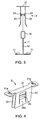
- a demounting tool 5 may be provided in a second aspect of the invention.
- the tool 5 is a scissor-type demounting tool, which comprises gripping members 51 adapted to abut the panel-facing surface of the support flanges 11 of the T-shaped profile 1 for pulling the profile 1 away from the clip 2 if the profile 1 is to be demounted from the clips 2.
- these gripping members 51 can easily be inserted in between the panel and the support flange 11 of the T-shaped profile 1.
- the profile 1 can then easily be gripped by the tool 5 as the flat gripping members 51 then has a firm connection with the profile 1 so that the profile 1 can be pulled out of the clip.
- T24 profiles have a 24mm wide front capping (visible side) for covering (and holding) the edges of the wall panels 4 underneath and with an approx. 6.5mm wide bulb 10 on the back side - the bulb 10 is clicked / pressed / pushed into the clips 2 (also referenced to as T fixing bracket for this embodiment).
- T24 profiles 1 to the clips 2 is strong and safe enough against accidental T24 removal with hands or fingers with damaging T24 front capping, when T24 profiles 1 are mounted on the wall in the T fixing brackets' channels between two wall panels 4, so the linear connections (gap) between two wall panels 4 are completely covered by T24 profiles' front capping (visible side). Furthermore, it is found that the connection is easily demountable afterwards with a removal tool 5 of special design shape without damaging T24 profile's front capping, so the T24 profile can be reused.
- the T24 profile's bulb 10 is driven between two open ends 22b (wide wings) of special shape, driving the bulb 10 into the two narrow ends (narrow wings), open in a suitable angle, such as approx. 30° angle.
- An angle of approx. 30° ensures that T24 profile's bulb 10 can easily enter into the narrow wings 22.
- the protrusions 23 are angled at 45°, so they keep the bulb 10 of the T24 profile 1 inside the T fixing bracket 2 in a firm and safe enough way.
- the narrow wings 22a integrated in the wide wings 23 are designed to achieve enough flexibility, which in connection with steel type and thickness thereof makes narrow wings 22a, 23 (45° angle on one side and 30° angled on second side) flexible enough and strong enough.
- the wide wings 22 of T fixing brackets are stiff enough to keep the T24 profiles positioned properly on the wall 3 - perpendicular to the wall surface - when T24 profiles 1 are fixed in the T fixing brackets 2.
- the surface of bigger wings can also deliver some bottom support for the 40mm thick wall panels in common with supporting brackets accompanying.
- the load of each wall panel 4 is delivered individually to the wall mainly by angle supporting brackets, whilst T fixing brackets can transfer some load as well to support the supporting brackets.
- the T fixing bracket 2 in fig. 6 and 7 is provided with a base portion having mounting flanges 21b arranged to one side of the T fixing bracket, and the mounting flanges 21b have mounting holes 21a arranged therein for mounting the T fixing bracket to a support structure 3.
- the shape of the holes 21a, preferably long holes, used in the T fixing brackets 1 gives a possibility to adjust the T fixing bracket's position on the wall 3 - left and right or up and down (depending on if it is side fixing brackets for vertical T24 profiles or bottom fixing brackets for horizontal T24 profiles on the wall) - even when the T24 profile is positioned in the T fixing bracket, but before the wall panels are installed between them - the holes 21a are "outside" the 24mm front capping surface, so the screws can be untwisted and twisted easily to ensure proper position of all the T fixing brackets 2 and T24 profiles 1 before the wall panels 4 are mounted.
- T profiles 1 are provided with holes arranged in the web portion 12 thereof, and these holes can be used for this purpose.
- a screw or nail can be driven through the profile 1 and clip 2 to secure that the profiles 1 cannot be removed from the clips 2. This may also be an extra security measure when the clips 2 and profiles 1 are used for mounting on a ceiling, to avoid the potential risk that profiles 1 and panels 4 fall down.
Landscapes
- Engineering & Computer Science (AREA)
- Architecture (AREA)
- Physics & Mathematics (AREA)
- Electromagnetism (AREA)
- Civil Engineering (AREA)
- Structural Engineering (AREA)
- Connection Of Plates (AREA)
- Finishing Walls (AREA)
Priority Applications (4)
| Application Number | Priority Date | Filing Date | Title |
|---|---|---|---|
| ES11182511.3T ES2552161T3 (es) | 2011-09-23 | 2011-09-23 | Sistema de soporte para el montaje de una rejilla de panel o estructura de soporte de pared |
| PL11182511T PL2573290T3 (pl) | 2011-09-23 | 2011-09-23 | System nośny do montażu kratki panelowej w suficie lub konstrukcji ściany nośnej |
| DK11182511.3T DK2573290T3 (en) | 2011-09-23 | 2011-09-23 | Support system for mounting a plate grid ceiling or vægstøttestruktur |
| EP11182511.3A EP2573290B1 (en) | 2011-09-23 | 2011-09-23 | A support system for mounting a panel grid in ceiling or wall support structure |
Applications Claiming Priority (1)
| Application Number | Priority Date | Filing Date | Title |
|---|---|---|---|
| EP11182511.3A EP2573290B1 (en) | 2011-09-23 | 2011-09-23 | A support system for mounting a panel grid in ceiling or wall support structure |
Publications (2)
| Publication Number | Publication Date |
|---|---|
| EP2573290A1 EP2573290A1 (en) | 2013-03-27 |
| EP2573290B1 true EP2573290B1 (en) | 2015-08-12 |
Family
ID=45560625
Family Applications (1)
| Application Number | Title | Priority Date | Filing Date |
|---|---|---|---|
| EP11182511.3A Active EP2573290B1 (en) | 2011-09-23 | 2011-09-23 | A support system for mounting a panel grid in ceiling or wall support structure |
Country Status (4)
| Country | Link |
|---|---|
| EP (1) | EP2573290B1 (pl) |
| DK (1) | DK2573290T3 (pl) |
| ES (1) | ES2552161T3 (pl) |
| PL (1) | PL2573290T3 (pl) |
Families Citing this family (5)
| Publication number | Priority date | Publication date | Assignee | Title |
|---|---|---|---|---|
| US9194123B2 (en) | 2014-04-29 | 2015-11-24 | Awi Licensing Company | Ceiling system |
| US9187896B1 (en) * | 2014-11-26 | 2015-11-17 | Awi Licensing Company | Assembly for supporting ceiling panels and ceiling system incorporating the same |
| CN106284814B (zh) * | 2016-10-11 | 2018-08-10 | 浙江东鼎电子股份有限公司 | 一种组合式机房吊顶及其安装方法 |
| JP6778090B2 (ja) * | 2016-11-22 | 2020-10-28 | 大建工業株式会社 | ハンガーと該ハンガーを用いたシステム天井構造 |
| EP4112835B1 (en) * | 2021-07-01 | 2024-05-15 | Saint-Gobain Ecophon AB | A grid of profiles |
Citations (5)
| Publication number | Priority date | Publication date | Assignee | Title |
|---|---|---|---|---|
| US2780850A (en) | 1952-10-15 | 1957-02-12 | Patent & Licensing Corp | Construction clip |
| US3263388A (en) | 1963-12-18 | 1966-08-02 | Allen Z Bogert | Ceiling tile hanger installation |
| US5611185A (en) | 1995-04-19 | 1997-03-18 | Thomas B. Van Wyk | Surface mounted grid system and process of installation |
| US20060096219A1 (en) | 2004-09-07 | 2006-05-11 | Ingratta Anthony D | Seismic perimeter clip for suspended ceiling grid |
| US7712274B2 (en) | 2006-12-29 | 2010-05-11 | Usg Interiors, Inc. | Downwardly accessible lift-and-shift ceiling system |
Family Cites Families (7)
| Publication number | Priority date | Publication date | Assignee | Title |
|---|---|---|---|---|
| US3390856A (en) * | 1966-06-10 | 1968-07-02 | United Carr Inc | Acoustical inverted t beam hanger |
| DK133480B (da) * | 1973-08-29 | 1976-05-24 | Finn Andersen | Underloft. |
| DE4038209A1 (de) * | 1990-11-30 | 1992-06-04 | Richter System Gmbh & Co Kg | Abhaenger fuer unterdecken |
| EP0541958B1 (de) * | 1991-11-13 | 1998-09-09 | Heraklith Ag | Befestigungssystem zum nachträglichen Anbringen von Abdeckplatten |
| AU2001268759A1 (en) * | 2000-05-25 | 2001-12-03 | King-Wah Chui | Front access strip |
| US20020112424A1 (en) | 2001-02-22 | 2002-08-22 | Vib Inc. | Suspended ceiling support structure |
| KR100541361B1 (ko) * | 2003-12-24 | 2006-01-10 | 주식회사 파라다이스산업 | 스프링클러 장착장치 |
-
2011
- 2011-09-23 EP EP11182511.3A patent/EP2573290B1/en active Active
- 2011-09-23 DK DK11182511.3T patent/DK2573290T3/en active
- 2011-09-23 ES ES11182511.3T patent/ES2552161T3/es active Active
- 2011-09-23 PL PL11182511T patent/PL2573290T3/pl unknown
Patent Citations (5)
| Publication number | Priority date | Publication date | Assignee | Title |
|---|---|---|---|---|
| US2780850A (en) | 1952-10-15 | 1957-02-12 | Patent & Licensing Corp | Construction clip |
| US3263388A (en) | 1963-12-18 | 1966-08-02 | Allen Z Bogert | Ceiling tile hanger installation |
| US5611185A (en) | 1995-04-19 | 1997-03-18 | Thomas B. Van Wyk | Surface mounted grid system and process of installation |
| US20060096219A1 (en) | 2004-09-07 | 2006-05-11 | Ingratta Anthony D | Seismic perimeter clip for suspended ceiling grid |
| US7712274B2 (en) | 2006-12-29 | 2010-05-11 | Usg Interiors, Inc. | Downwardly accessible lift-and-shift ceiling system |
Non-Patent Citations (3)
| Title |
|---|
| FOCUS DS DIRECTION INSTALLATION, 2008 |
| INSTALLATION GUIDE ECOPHON EDGE WITH FOCUS E, 2008 |
| WINGLIGHT CORRIDOR, 2009 |
Also Published As
| Publication number | Publication date |
|---|---|
| ES2552161T3 (es) | 2015-11-26 |
| DK2573290T3 (en) | 2015-11-09 |
| PL2573290T3 (pl) | 2016-01-29 |
| EP2573290A1 (en) | 2013-03-27 |
Similar Documents
| Publication | Publication Date | Title |
|---|---|---|
| US11753822B2 (en) | Ceiling system | |
| EP2573290B1 (en) | A support system for mounting a panel grid in ceiling or wall support structure | |
| RU2622415C2 (ru) | Фиксатор для соединения несущего прогона решетки с полоской, расположенной по периметру | |
| US9376812B2 (en) | Ceiling panel mounting system | |
| EP2254211B1 (en) | Telescoping wire cable tray system | |
| CA2788878C (en) | Fastener-less track assembly for supporting wall studs | |
| US20170342736A1 (en) | Track system for supporting wall studs | |
| US20150340987A1 (en) | Device for supporting at least one solar panel | |
| US9228372B2 (en) | Fence rail and bracket system | |
| US8955272B1 (en) | Accessible stabilizer bar | |
| DK3097240T3 (en) | CLAMP TO GRID SYSTEM FOR RECOVERED AIR TO DETERMINATE A TENSION-FREE TRANSFER TO A HEADBAR | |
| EP2706162B1 (en) | Suspended ceiling grid adapter | |
| KR20160031435A (ko) | 케이블 트레이 지지체 | |
| EP3122952B1 (en) | Ceiling suspension system | |
| EP2741017B1 (en) | Grille support | |
| EP3635191B1 (en) | A construction system for wall cladding | |
| EP3773072B1 (en) | Hook member for modular furniture | |
| EP4632166A1 (en) | Cross runner and suspended ceiling system | |
| AU777109B2 (en) | Hanging clip | |
| NZ500862A (en) | Ceiling panel support system including parallel main runners supporting tiles and interconnected by transverse struts obscured by the tiles |
Legal Events
| Date | Code | Title | Description |
|---|---|---|---|
| PUAI | Public reference made under article 153(3) epc to a published international application that has entered the european phase |
Free format text: ORIGINAL CODE: 0009012 |
|
| AK | Designated contracting states |
Kind code of ref document: A1 Designated state(s): AL AT BE BG CH CY CZ DE DK EE ES FI FR GB GR HR HU IE IS IT LI LT LU LV MC MK MT NL NO PL PT RO RS SE SI SK SM TR |
|
| AX | Request for extension of the european patent |
Extension state: BA ME |
|
| 17P | Request for examination filed |
Effective date: 20130926 |
|
| RBV | Designated contracting states (corrected) |
Designated state(s): AL AT BE BG CH CY CZ DE DK EE ES FI FR GB GR HR HU IE IS IT LI LT LU LV MC MK MT NL NO PL PT RO RS SE SI SK SM TR |
|
| 17Q | First examination report despatched |
Effective date: 20140122 |
|
| GRAP | Despatch of communication of intention to grant a patent |
Free format text: ORIGINAL CODE: EPIDOSNIGR1 |
|
| INTG | Intention to grant announced |
Effective date: 20150302 |
|
| GRAS | Grant fee paid |
Free format text: ORIGINAL CODE: EPIDOSNIGR3 |
|
| GRAA | (expected) grant |
Free format text: ORIGINAL CODE: 0009210 |
|
| AK | Designated contracting states |
Kind code of ref document: B1 Designated state(s): AL AT BE BG CH CY CZ DE DK EE ES FI FR GB GR HR HU IE IS IT LI LT LU LV MC MK MT NL NO PL PT RO RS SE SI SK SM TR |
|
| REG | Reference to a national code |
Ref country code: GB Ref legal event code: FG4D |
|
| REG | Reference to a national code |
Ref country code: CH Ref legal event code: EP |
|
| REG | Reference to a national code |
Ref country code: AT Ref legal event code: REF Ref document number: 742303 Country of ref document: AT Kind code of ref document: T Effective date: 20150815 |
|
| REG | Reference to a national code |
Ref country code: FR Ref legal event code: PLFP Year of fee payment: 5 |
|
| REG | Reference to a national code |
Ref country code: IE Ref legal event code: FG4D |
|
| REG | Reference to a national code |
Ref country code: DE Ref legal event code: R096 Ref document number: 602011018620 Country of ref document: DE |
|
| REG | Reference to a national code |
Ref country code: DK Ref legal event code: T3 Effective date: 20151103 |
|
| REG | Reference to a national code |
Ref country code: ES Ref legal event code: FG2A Ref document number: 2552161 Country of ref document: ES Kind code of ref document: T3 Effective date: 20151126 |
|
| REG | Reference to a national code |
Ref country code: SE Ref legal event code: TRGR |
|
| REG | Reference to a national code |
Ref country code: NO Ref legal event code: T2 Effective date: 20150812 |
|
| REG | Reference to a national code |
Ref country code: LT Ref legal event code: MG4D |
|
| REG | Reference to a national code |
Ref country code: AT Ref legal event code: MK05 Ref document number: 742303 Country of ref document: AT Kind code of ref document: T Effective date: 20150812 |
|
| REG | Reference to a national code |
Ref country code: NL Ref legal event code: FP |
|
| PG25 | Lapsed in a contracting state [announced via postgrant information from national office to epo] |
Ref country code: LT Free format text: LAPSE BECAUSE OF FAILURE TO SUBMIT A TRANSLATION OF THE DESCRIPTION OR TO PAY THE FEE WITHIN THE PRESCRIBED TIME-LIMIT Effective date: 20150812 Ref country code: LV Free format text: LAPSE BECAUSE OF FAILURE TO SUBMIT A TRANSLATION OF THE DESCRIPTION OR TO PAY THE FEE WITHIN THE PRESCRIBED TIME-LIMIT Effective date: 20150812 Ref country code: GR Free format text: LAPSE BECAUSE OF FAILURE TO SUBMIT A TRANSLATION OF THE DESCRIPTION OR TO PAY THE FEE WITHIN THE PRESCRIBED TIME-LIMIT Effective date: 20151113 |
|
| PG25 | Lapsed in a contracting state [announced via postgrant information from national office to epo] |
Ref country code: PT Free format text: LAPSE BECAUSE OF FAILURE TO SUBMIT A TRANSLATION OF THE DESCRIPTION OR TO PAY THE FEE WITHIN THE PRESCRIBED TIME-LIMIT Effective date: 20151214 Ref country code: AT Free format text: LAPSE BECAUSE OF FAILURE TO SUBMIT A TRANSLATION OF THE DESCRIPTION OR TO PAY THE FEE WITHIN THE PRESCRIBED TIME-LIMIT Effective date: 20150812 Ref country code: IS Free format text: LAPSE BECAUSE OF FAILURE TO SUBMIT A TRANSLATION OF THE DESCRIPTION OR TO PAY THE FEE WITHIN THE PRESCRIBED TIME-LIMIT Effective date: 20151212 Ref country code: HR Free format text: LAPSE BECAUSE OF FAILURE TO SUBMIT A TRANSLATION OF THE DESCRIPTION OR TO PAY THE FEE WITHIN THE PRESCRIBED TIME-LIMIT Effective date: 20150812 Ref country code: RS Free format text: LAPSE BECAUSE OF FAILURE TO SUBMIT A TRANSLATION OF THE DESCRIPTION OR TO PAY THE FEE WITHIN THE PRESCRIBED TIME-LIMIT Effective date: 20150812 |
|
| PG25 | Lapsed in a contracting state [announced via postgrant information from national office to epo] |
Ref country code: SK Free format text: LAPSE BECAUSE OF FAILURE TO SUBMIT A TRANSLATION OF THE DESCRIPTION OR TO PAY THE FEE WITHIN THE PRESCRIBED TIME-LIMIT Effective date: 20150812 Ref country code: CZ Free format text: LAPSE BECAUSE OF FAILURE TO SUBMIT A TRANSLATION OF THE DESCRIPTION OR TO PAY THE FEE WITHIN THE PRESCRIBED TIME-LIMIT Effective date: 20150812 Ref country code: EE Free format text: LAPSE BECAUSE OF FAILURE TO SUBMIT A TRANSLATION OF THE DESCRIPTION OR TO PAY THE FEE WITHIN THE PRESCRIBED TIME-LIMIT Effective date: 20150812 |
|
| REG | Reference to a national code |
Ref country code: CH Ref legal event code: PL |
|
| REG | Reference to a national code |
Ref country code: DE Ref legal event code: R026 Ref document number: 602011018620 Country of ref document: DE |
|
| PLBI | Opposition filed |
Free format text: ORIGINAL CODE: 0009260 |
|
| PG25 | Lapsed in a contracting state [announced via postgrant information from national office to epo] |
Ref country code: RO Free format text: LAPSE BECAUSE OF FAILURE TO SUBMIT A TRANSLATION OF THE DESCRIPTION OR TO PAY THE FEE WITHIN THE PRESCRIBED TIME-LIMIT Effective date: 20150812 Ref country code: MC Free format text: LAPSE BECAUSE OF FAILURE TO SUBMIT A TRANSLATION OF THE DESCRIPTION OR TO PAY THE FEE WITHIN THE PRESCRIBED TIME-LIMIT Effective date: 20150812 |
|
| PLAX | Notice of opposition and request to file observation + time limit sent |
Free format text: ORIGINAL CODE: EPIDOSNOBS2 |
|
| 26 | Opposition filed |
Opponent name: SAINT-GOBAIN ECOPHON AB Effective date: 20160512 |
|
| REG | Reference to a national code |
Ref country code: IE Ref legal event code: MM4A |
|
| PG25 | Lapsed in a contracting state [announced via postgrant information from national office to epo] |
Ref country code: IE Free format text: LAPSE BECAUSE OF NON-PAYMENT OF DUE FEES Effective date: 20150923 Ref country code: CH Free format text: LAPSE BECAUSE OF NON-PAYMENT OF DUE FEES Effective date: 20150930 Ref country code: LI Free format text: LAPSE BECAUSE OF NON-PAYMENT OF DUE FEES Effective date: 20150930 |
|
| REG | Reference to a national code |
Ref country code: FR Ref legal event code: PLFP Year of fee payment: 6 |
|
| PG25 | Lapsed in a contracting state [announced via postgrant information from national office to epo] |
Ref country code: SI Free format text: LAPSE BECAUSE OF FAILURE TO SUBMIT A TRANSLATION OF THE DESCRIPTION OR TO PAY THE FEE WITHIN THE PRESCRIBED TIME-LIMIT Effective date: 20150812 |
|
| PLBB | Reply of patent proprietor to notice(s) of opposition received |
Free format text: ORIGINAL CODE: EPIDOSNOBS3 |
|
| PG25 | Lapsed in a contracting state [announced via postgrant information from national office to epo] |
Ref country code: MT Free format text: LAPSE BECAUSE OF FAILURE TO SUBMIT A TRANSLATION OF THE DESCRIPTION OR TO PAY THE FEE WITHIN THE PRESCRIBED TIME-LIMIT Effective date: 20150812 |
|
| PG25 | Lapsed in a contracting state [announced via postgrant information from national office to epo] |
Ref country code: HU Free format text: LAPSE BECAUSE OF FAILURE TO SUBMIT A TRANSLATION OF THE DESCRIPTION OR TO PAY THE FEE WITHIN THE PRESCRIBED TIME-LIMIT; INVALID AB INITIO Effective date: 20110923 Ref country code: SM Free format text: LAPSE BECAUSE OF FAILURE TO SUBMIT A TRANSLATION OF THE DESCRIPTION OR TO PAY THE FEE WITHIN THE PRESCRIBED TIME-LIMIT Effective date: 20150812 Ref country code: BG Free format text: LAPSE BECAUSE OF FAILURE TO SUBMIT A TRANSLATION OF THE DESCRIPTION OR TO PAY THE FEE WITHIN THE PRESCRIBED TIME-LIMIT Effective date: 20150812 |
|
| PG25 | Lapsed in a contracting state [announced via postgrant information from national office to epo] |
Ref country code: CY Free format text: LAPSE BECAUSE OF FAILURE TO SUBMIT A TRANSLATION OF THE DESCRIPTION OR TO PAY THE FEE WITHIN THE PRESCRIBED TIME-LIMIT Effective date: 20150812 |
|
| REG | Reference to a national code |
Ref country code: FR Ref legal event code: PLFP Year of fee payment: 7 |
|
| PG25 | Lapsed in a contracting state [announced via postgrant information from national office to epo] |
Ref country code: LU Free format text: LAPSE BECAUSE OF NON-PAYMENT OF DUE FEES Effective date: 20150923 |
|
| APBM | Appeal reference recorded |
Free format text: ORIGINAL CODE: EPIDOSNREFNO |
|
| APBP | Date of receipt of notice of appeal recorded |
Free format text: ORIGINAL CODE: EPIDOSNNOA2O |
|
| APAH | Appeal reference modified |
Free format text: ORIGINAL CODE: EPIDOSCREFNO |
|
| APBM | Appeal reference recorded |
Free format text: ORIGINAL CODE: EPIDOSNREFNO |
|
| APBP | Date of receipt of notice of appeal recorded |
Free format text: ORIGINAL CODE: EPIDOSNNOA2O |
|
| PG25 | Lapsed in a contracting state [announced via postgrant information from national office to epo] |
Ref country code: MK Free format text: LAPSE BECAUSE OF FAILURE TO SUBMIT A TRANSLATION OF THE DESCRIPTION OR TO PAY THE FEE WITHIN THE PRESCRIBED TIME-LIMIT Effective date: 20150812 |
|
| APBQ | Date of receipt of statement of grounds of appeal recorded |
Free format text: ORIGINAL CODE: EPIDOSNNOA3O |
|
| APBQ | Date of receipt of statement of grounds of appeal recorded |
Free format text: ORIGINAL CODE: EPIDOSNNOA3O |
|
| REG | Reference to a national code |
Ref country code: FR Ref legal event code: PLFP Year of fee payment: 8 |
|
| PG25 | Lapsed in a contracting state [announced via postgrant information from national office to epo] |
Ref country code: AL Free format text: LAPSE BECAUSE OF FAILURE TO SUBMIT A TRANSLATION OF THE DESCRIPTION OR TO PAY THE FEE WITHIN THE PRESCRIBED TIME-LIMIT Effective date: 20150812 |
|
| PLAB | Opposition data, opponent's data or that of the opponent's representative modified |
Free format text: ORIGINAL CODE: 0009299OPPO |
|
| R26 | Opposition filed (corrected) |
Opponent name: SAINT-GOBAIN ECOPHON AB Effective date: 20160512 |
|
| REG | Reference to a national code |
Ref country code: DE Ref legal event code: R100 Ref document number: 602011018620 Country of ref document: DE |
|
| APBU | Appeal procedure closed |
Free format text: ORIGINAL CODE: EPIDOSNNOA9O |
|
| PLCK | Communication despatched that opposition was rejected |
Free format text: ORIGINAL CODE: EPIDOSNREJ1 |
|
| STAA | Information on the status of an ep patent application or granted ep patent |
Free format text: STATUS: OPPOSITION REJECTED |
|
| PLBN | Opposition rejected |
Free format text: ORIGINAL CODE: 0009273 |
|
| 27O | Opposition rejected |
Effective date: 20220324 |
|
| REG | Reference to a national code |
Ref country code: NO Ref legal event code: CHAD Owner name: ROCKWOOL A/S, DK |
|
| REG | Reference to a national code |
Ref country code: NL Ref legal event code: HC Owner name: ROCKWOOL A/S; DK Free format text: DETAILS ASSIGNMENT: CHANGE OF OWNER(S), CHANGE OF OWNER(S) NAME; FORMER OWNER NAME: ROCKWOOL INTERNATIONAL A/S Effective date: 20230728 |
|
| REG | Reference to a national code |
Ref country code: DE Ref legal event code: R081 Ref document number: 602011018620 Country of ref document: DE Owner name: ROCKWOOL A/S, DK Free format text: FORMER OWNER: ROCKWOOL INTERNATIONAL A/S, HEDEHUSENE, DK |
|
| REG | Reference to a national code |
Ref country code: ES Ref legal event code: PC2A Owner name: ROCKWOOL A/S Effective date: 20240423 |
|
| REG | Reference to a national code |
Ref country code: BE Ref legal event code: PD Owner name: ROCKWOOL INTERNATIONAL A/S; DK Free format text: DETAILS ASSIGNMENT: CHANGE OF OWNER(S), OTHER; FORMER OWNER NAME: ROCKWOOL INTERNATIONAL A/S Effective date: 20241212 Ref country code: BE Ref legal event code: HC Owner name: ROCKWOOL A/S; DK Free format text: DETAILS ASSIGNMENT: CHANGE OF OWNER(S), CHANGE OF OWNER(S) NAME; FORMER OWNER NAME: ROCKWOOL INTERNATIONAL A/S Effective date: 20241212 |
|
| PGFP | Annual fee paid to national office [announced via postgrant information from national office to epo] |
Ref country code: FI Payment date: 20250925 Year of fee payment: 15 |
|
| PGFP | Annual fee paid to national office [announced via postgrant information from national office to epo] |
Ref country code: DK Payment date: 20250925 Year of fee payment: 15 Ref country code: DE Payment date: 20250929 Year of fee payment: 15 |
|
| PGFP | Annual fee paid to national office [announced via postgrant information from national office to epo] |
Ref country code: NO Payment date: 20250929 Year of fee payment: 15 |
|
| PGFP | Annual fee paid to national office [announced via postgrant information from national office to epo] |
Ref country code: NL Payment date: 20250926 Year of fee payment: 15 Ref country code: PL Payment date: 20250904 Year of fee payment: 15 Ref country code: TR Payment date: 20250908 Year of fee payment: 15 Ref country code: IT Payment date: 20250919 Year of fee payment: 15 |
|
| PGFP | Annual fee paid to national office [announced via postgrant information from national office to epo] |
Ref country code: BE Payment date: 20250929 Year of fee payment: 15 Ref country code: GB Payment date: 20250929 Year of fee payment: 15 |
|
| PGFP | Annual fee paid to national office [announced via postgrant information from national office to epo] |
Ref country code: FR Payment date: 20250925 Year of fee payment: 15 |
|
| PGFP | Annual fee paid to national office [announced via postgrant information from national office to epo] |
Ref country code: SE Payment date: 20250927 Year of fee payment: 15 |
|
| PGFP | Annual fee paid to national office [announced via postgrant information from national office to epo] |
Ref country code: ES Payment date: 20251001 Year of fee payment: 15 |