EP2573288A1 - Waste water hoisting facility - Google Patents
Waste water hoisting facility Download PDFInfo
- Publication number
- EP2573288A1 EP2573288A1 EP20110182391 EP11182391A EP2573288A1 EP 2573288 A1 EP2573288 A1 EP 2573288A1 EP 20110182391 EP20110182391 EP 20110182391 EP 11182391 A EP11182391 A EP 11182391A EP 2573288 A1 EP2573288 A1 EP 2573288A1
- Authority
- EP
- European Patent Office
- Prior art keywords
- inlet pipe
- flange plate
- plant according
- collecting container
- sewage lifting
- Prior art date
- Legal status (The legal status is an assumption and is not a legal conclusion. Google has not performed a legal analysis and makes no representation as to the accuracy of the status listed.)
- Granted
Links
- 239000002351 wastewater Substances 0.000 title claims abstract description 16
- 238000009434 installation Methods 0.000 claims abstract description 3
- 239000010865 sewage Substances 0.000 claims description 20
- 238000010438 heat treatment Methods 0.000 claims description 10
- 230000002093 peripheral effect Effects 0.000 claims description 5
- 238000004378 air conditioning Methods 0.000 claims description 3
- 239000007789 gas Substances 0.000 description 25
- 239000007788 liquid Substances 0.000 description 8
- 230000004888 barrier function Effects 0.000 description 6
- 238000005192 partition Methods 0.000 description 4
- XLYOFNOQVPJJNP-UHFFFAOYSA-N water Substances O XLYOFNOQVPJJNP-UHFFFAOYSA-N 0.000 description 3
- 239000012535 impurity Substances 0.000 description 2
- 238000009825 accumulation Methods 0.000 description 1
- 230000002378 acidificating effect Effects 0.000 description 1
- 150000001875 compounds Chemical class 0.000 description 1
- 239000000356 contaminant Substances 0.000 description 1
- 230000008878 coupling Effects 0.000 description 1
- 238000010168 coupling process Methods 0.000 description 1
- 238000005859 coupling reaction Methods 0.000 description 1
- 230000004941 influx Effects 0.000 description 1
- 238000012423 maintenance Methods 0.000 description 1
- 239000000126 substance Substances 0.000 description 1
Images


Classifications
-
- E—FIXED CONSTRUCTIONS
- E03—WATER SUPPLY; SEWERAGE
- E03F—SEWERS; CESSPOOLS
- E03F5/00—Sewerage structures
- E03F5/22—Adaptations of pumping plants for lifting sewage
-
- E—FIXED CONSTRUCTIONS
- E03—WATER SUPPLY; SEWERAGE
- E03C—DOMESTIC PLUMBING INSTALLATIONS FOR FRESH WATER OR WASTE WATER; SINKS
- E03C1/00—Domestic plumbing installations for fresh water or waste water; Sinks
- E03C1/12—Plumbing installations for waste water; Basins or fountains connected thereto; Sinks
- E03C1/122—Pipe-line systems for waste water in building
- E03C1/1222—Arrangements of devices in domestic waste water pipe-line systems
- E03C1/1227—Arrangements of devices in domestic waste water pipe-line systems of pumps for facilitating drawing off
-
- F—MECHANICAL ENGINEERING; LIGHTING; HEATING; WEAPONS; BLASTING
- F04—POSITIVE - DISPLACEMENT MACHINES FOR LIQUIDS; PUMPS FOR LIQUIDS OR ELASTIC FLUIDS
- F04D—NON-POSITIVE-DISPLACEMENT PUMPS
- F04D15/00—Control, e.g. regulation, of pumps, pumping installations or systems
- F04D15/02—Stopping of pumps, or operating valves, on occurrence of unwanted conditions
- F04D15/0209—Stopping of pumps, or operating valves, on occurrence of unwanted conditions responsive to a condition of the working fluid
- F04D15/0218—Stopping of pumps, or operating valves, on occurrence of unwanted conditions responsive to a condition of the working fluid the condition being a liquid level or a lack of liquid supply
-
- F—MECHANICAL ENGINEERING; LIGHTING; HEATING; WEAPONS; BLASTING
- F04—POSITIVE - DISPLACEMENT MACHINES FOR LIQUIDS; PUMPS FOR LIQUIDS OR ELASTIC FLUIDS
- F04D—NON-POSITIVE-DISPLACEMENT PUMPS
- F04D13/00—Pumping installations or systems
- F04D13/16—Pumping installations or systems with storage reservoirs
-
- Y—GENERAL TAGGING OF NEW TECHNOLOGICAL DEVELOPMENTS; GENERAL TAGGING OF CROSS-SECTIONAL TECHNOLOGIES SPANNING OVER SEVERAL SECTIONS OF THE IPC; TECHNICAL SUBJECTS COVERED BY FORMER USPC CROSS-REFERENCE ART COLLECTIONS [XRACs] AND DIGESTS
- Y10—TECHNICAL SUBJECTS COVERED BY FORMER USPC
- Y10T—TECHNICAL SUBJECTS COVERED BY FORMER US CLASSIFICATION
- Y10T137/00—Fluid handling
- Y10T137/6851—With casing, support, protector or static constructional installations
Definitions
- the invention relates to a wastewater lifting plant with the features specified in the preamble of claim 1.
- Wastewater lifting plants are used to pump sewage, which is below the level of the existing sewers or sewer, to the higher level of the sewer or sewage system.
- Such sewage lifting plants usually have a collecting container, in which flows in to be lifted or pumped wastewater.
- a pump which pumps out the waste water, when the level of the collecting container has reached a predetermined level, from the collecting container.
- a level switch is provided in the reservoir.
- Level switch and pump are often mounted on a lid or a flange plate, which is placed on top of the collecting container. For maintenance purposes, the flange plate can be removed from the sump, with the flange plate the level switch and the pump unit are removed from the sump.
- the level switch which is usually designed as a float switch, can be easily damaged.
- the wastewater lifting plant according to the invention has a collecting container. In this flows to be lifted or to be pumped to a higher level wastewater. Upon reaching a predetermined level, a pump in the sewage lifting plant is then turned on to pump the water out of the sump to a higher level.
- a level switch immersing in the collecting tank is provided which can switch a pump on and off depending on the water level in the interior of the collecting tank.
- a flange plate or a cover is arranged at the top of the collecting container, on which the level switch is mounted so that it dips into the collecting container.
- the level switch may in particular be designed as a float switch, which has a floating body arranged in the collecting container.
- the float is coupled in a known manner with a switching mechanism for switching on and off the pump upon reaching predetermined liquid levels.
- This can be for example a mechanical coupling which actuates an electrical switching contact.
- at least one inlet pipe extends vertically downwards into the collecting container.
- This inlet pipe serves as an inlet for the waste water in the collecting container.
- the inlet pipe is connected at its upper side, ie in the region of the flange plate or above the flange plate with an incoming line.
- the at least one inlet pipe has a vertical length such that the lower end of the inlet pipe is vertically spaced farther from the flange plate than a lower end of the level switch.
- a plurality, more preferably three or four inlet pipes are arranged on the flange plate, which extend from the flange plate into the collecting container, wherein the inlet pipes have a vertical length such that their lower ends are each vertically further spaced from the flange plate than a lower one End of the level switch.
- these multiple inlet pipes are spaced from each other so that the assembly consisting of flange plate, level switch and optionally other components can be stable on the lower ends of the inlet pipes without the level switch touches the surface on which the unit is placed. This prevents damage to the level switch.
- four inlet pipes are arranged at four spaced-apart corners of a substantially rectangular flange plate.
- each inlet pipe actually serves as inlet or inlet.
- the multiple inlet pipes can optionally form to be connected feeds, so that, for example, a supply line can be selectively connected to one of the inlet pipes, depending on where and how the wastewater lifting plant is set up and how the sewer pipes to be connected are located.
- a supply line can be selectively connected to one of the inlet pipes, depending on where and how the wastewater lifting plant is set up and how the sewer pipes to be connected are located.
- optional connections to be connected from different directions can be provided.
- the flange plate also carries the pump unit, d. H. an electric motor with a pump, in particular a centrifugal pump.
- the pump is preferably designed such that the impeller is immersed in the collecting container and the electric motor is located above the flange plate, wherein the electric motor and impeller are connected to each other via a shaft.
- the lower end of the at least one inlet pipe or form the lower ends of the plurality of inlet pipes, the lowest point or the lowest point of all attached to the flange plate components. This ensures that when the flange plate is parked with the components attached to it on the lower ends of the inlet pipes, the other arranged on the flange plate components do not come into contact with the footprint and can not be damaged by the setting up.
- the at least one inlet pipe has at least one outlet opening vertically spaced from its lower end.
- the at least one inlet pipe on a closed end wall and at least one located in a peripheral wall of the inlet pipe outlet opening is located vertically downwardly spaced from the flange plate and thus closes the flow path formed by the inlet pipe downwards from.
- the end wall is thus preferably located near the lower end of the inlet pipe, ie closer to the lower end than to the flange plate. Characterized in that the outlet opening is located simultaneously in the peripheral wall, it is prevented that impurities can enter the outlet opening when the flange plate is placed with the components attached to it on the lower end of the inlet pipes.
- the at least one inlet pipe preferably has a foot element which extends vertically downwards from the end wall to the lower end of the inlet pipe.
- the foot element forms the actual lower end of the inlet pipe.
- This foot element can be designed, for example, as a sleeve or projection, which extends vertically downwards from the end wall.
- the foot element has on its underside preferably a flat footprint on to ensure a stable stand when parking.
- the at least one inlet pipe is formed integrally with the flange plate, preferably made of plastic.
- the at least one inlet pipe or preferably all inlet pipes can be manufactured in one operation together with the flange plate, for example as an injection-molded component.
- the at least one inlet pipe engages with its lower end in an inlet chamber of the collecting container and forms together with this a gas seal or a gas barrier.
- the inlet chamber of the collecting container is preferably formed so that, for example, by an upwardly extending from the bottom of the collecting container wall, an upwardly open inlet chamber is formed. In this engages from above the lower end of the inlet pipe so that its outlet opening is located below the upper edge of the upwardly open inlet chamber. So is a gas barrier created in the manner of a siphon, which prevents an influx of gases through the inlet pipe into the collecting container inside.
- the at least one inlet pipe can more preferably have at least one gas outlet opening at its upper end. Gas, which flows through a supply line connected to the inlet pipe, can be discharged to the outside into the environment through a gas outlet opening, if, for example, it can not flow further into the collecting container due to the gas barrier.
- the gas outlet opening is preferably formed between a seal inserted into the upper end of the inlet pipe and a peripheral wall of the inlet pipe.
- a recess or a gap can be provided, through which gas can escape to the outside.
- the seal is preferably sealingly on the outer circumference of an inflow or connection pipe inserted into the inlet pipe or is sealingly engageable on the outer periphery of such a pipe.
- the wastewater lifting plant is particularly preferably designed as a condensate lifting plant, more preferably for use in a heating and / or air conditioning system.
- condensate lifting systems for heating systems must be so designed be that they are resistant to contained in the condensate chemical compounds, especially against the most acidic pH of the condensate.
- the wastewater lifting plant shown by way of example has an upwardly open collecting container 2, which is preferably designed as a molded part made of plastic. At the top of the collecting container 2 is closed by a flange plate 4, which forms a lid for the collecting container 2.
- the flange plate 4 carries all the essential components of sewage lifting plant. Thus, it bears in particular a pump unit 6, with an above the flange plate 4 arranged electric motor 8 and arranged below the flange plate 4 pump 10.
- the pump 10 is arranged so that it dips into the interior of the collecting container 2 and its impeller as far down located in the interior of the collecting container 2.
- a float switch 12 is arranged on the flange plate 4, which serves for switching on and off of the pump unit 6.
- the float switch 12 has a float 14 arranged inside the collecting container 2, ie below the flange plate.
- the float 14 is connected by means of an actuating rod 16 with an electrical switch 18 located above the flange plate 4.
- the electrical switch 18 As the liquid level in the sump 2 rises, it floats the float 14 upwards and actuated via the actuating rod 16, the electrical switch 18 so that the electric motor 8 is turned on and driven by this, the pump 10, so that liquid is conveyed out of the sump to the outside.
- the float 14 drops down and actuates the electric switch 18 via the actuating rod 16 so that the electric motor 8 is switched off again.
- the flange plate 4 has at its four corners in each case a vertically downwardly extending inlet pipe 22.
- the inlet pipes 22 are in this case formed integrally with the flange plate 4 made of plastic.
- a seal 24 is used in each case, which serves to seal a connecting pipe 26 used.
- All four inlet pipes 22 are of identical design, and can optionally be used to connect a connecting pipe 26, depending on which direction the waste water is to be supplied to the collecting tank 2.
- the connecting pipe 26 is simply inserted from above into the inlet pipe 22 and sealingly comes into contact with the inner circumference of the seal 24. With its outer circumference, the seal 24 is sealingly against the inner circumference of the inlet pipe 22.
- the inlet pipes 22 are formed so long in the vertical direction X that their lower ends 28 in the vertical direction X of the flange plate 4 are spaced further than the lower end of the float 14. In this way it is achieved that when the flange plate 4 from taken from the sump 2 and placed on a flat surface, the flange plate 4 comes to rest with the attached components, in particular the float 14 and the pump 10 on the lower ends 28 of the inlet pipes 22 and the float 14 ideally not with the shelf in Contact is coming. This will be a damage the float 14 or connected to this via the actuating rod 16 electrical switch 18 when parking the flange plate 4 is prevented.
- the inlet pipes 22 are not open directly at their lower ends 28 but have radially directed outlet openings 30, which are each spaced from the lower end 28 vertically upwards. This ensures that the outlet openings, through which liquid or water flows into the collecting container 2, are not located directly at the bottom of the collecting container 2, so that they can not become clogged by contaminants accumulating on the bottom of the collecting container 2.
- the inlet pipes 22 have a transversely extending closed end wall 32, from which an annular foot member 34 extends vertically down to the lower end 28. The end wall 32 in each case closes off the flow path or channel in the interior of the inlet pipe 22 downwards.
- the inlet tubes 22 engage with their lower end and the lower end portion, in which the outlet openings 30 are located, each in an inlet chamber 36 a.
- the inlet bosses 36 are formed in the corners of the header tank 2 by partition walls 38 which extend vertically upward from the bottom of the header tank 2 and connect to the side walls of the header tank 2.
- the partitions 38 are integrally formed with the walls of the collecting container 2, preferably made of plastic.
- inlet chambers 36 are formed, which are open only upwards, wherein the upper end 40 of the inlet chambers 36 are located above the upper edge of the outlet openings 30 of the inlet pipes 22. In this way, a gas barrier is formed.
- the inlet chamber 36 first fills with liquid up to the upper edge 40.
- the liquid then flows into the remaining region of the collecting container 2, in which the float 14 and the pump 10 are arranged. This ensures that the outlet openings 30 of the inlet pipe are always in the liquid, so that no gas from the inlet pipe 22 can flow into the interior of the collecting container 2. If gas flows through the connecting pipe 26 into the inlet pipe 22, this can be done by a gas outlet opening 42, which is formed by a gap between the outer circumference of the seal 24 and the inner circumference of the inlet pipe 22 at its upper end.
- This embodiment of the gas barrier is particularly advantageous if the wastewater lifting plant, as provided in the sewage lifting plant shown, is used as a condensate lifting plant in a heating system.
- exhaust gas from the heating system flows through the connecting pipe 26 to the sump 2. Since this exhaust gas contains aggressive substances, the exhaust gas should not enter into the interior of the collecting container 2, which is prevented by the described gas barrier, which is formed by the partition wall 38. Instead, the exhaust gas is then discharged through the gas outlet opening 42 into the environment.
- the flange plate 4 next to the inlet pipes only small openings, namely an opening 44 through which the actuating rod 16 extends, and an opening 46 through which a shaft of the pump assembly extends from the electric motor 8 to the pump 10. Further, an opening 48 is provided, through which an outlet line, not shown here, may extend from the pump 10 to the outside. In addition, only mounting holes are still provided.
Abstract
Description
Die Erfindung betrifft eine Abwasserhebeanlage mit den im Oberbegriff des Anspruch 1 angegebenen Merkmalen.The invention relates to a wastewater lifting plant with the features specified in the preamble of claim 1.
Abwasserhebeanlagen werden eingesetzt, um Abwässer, welche unterhalb des Niveaus der bestehenden Abwasserleitungen bzw. der Kanalisation anfallen, auf das höhere Niveau der Abwasserleitung bzw. Kanalisation zu pumpen.Wastewater lifting plants are used to pump sewage, which is below the level of the existing sewers or sewer, to the higher level of the sewer or sewage system.
Derartige Abwasserhebeanlagen weisen meist einen Sammelbehälter auf, in welchen das zu hebende bzw. zu pumpende Abwasser einströmt. In dem Sammelbehälter befindet sich eine Pumpe, welche das Abwasser, wenn der Füllstand des Sammelbehälters ein vorbestimmtes Niveau erreicht hat, aus dem Sammelbehälter herauspumpt. Zum Ein-und Ausschalten der Pumpe ist in dem Sammelbehälter üblicherweise ein Niveauschalter vorgesehen. Niveauschalter und Pumpe sind dabei häufig an einem Deckel bzw. einer Flanschplatte montiert, welche auf die Oberseite des Sammelbehälters aufgesetzt wird. Zu Wartungszwecken kann die Flanschplatte von dem Sammelbehälter abgenommen werden, wobei mit der Flanschplatte der Niveauschalter und das Pumpenaggregat aus dem Sammelbehälter entnommen werden. Problematisch ist dabei, dass, wenn die so entnommene Flanschplatte mit dem Niveauschalter außerhalb des Sammelbehälters abgestellt wird, der Niveauschalter, welcher meist als Schwimmerschalter ausgebildet ist, leicht beschädigt werden kann.Such sewage lifting plants usually have a collecting container, in which flows in to be lifted or pumped wastewater. In the collecting container is a pump which pumps out the waste water, when the level of the collecting container has reached a predetermined level, from the collecting container. To turn the pump on and off usually a level switch is provided in the reservoir. Level switch and pump are often mounted on a lid or a flange plate, which is placed on top of the collecting container. For maintenance purposes, the flange plate can be removed from the sump, with the flange plate the level switch and the pump unit are removed from the sump. The problem is that, if the thus removed flange plate is turned off with the level switch outside of the collecting container, the level switch, which is usually designed as a float switch, can be easily damaged.
Im Hinblick auf diese Problematik ist es Aufgabe der Erfindung, eine verbesserte Abwasserhabeanlage zu schaffen, bei welcher der Niveauschalter besser vor Beschädigungen geschützt ist.In view of this problem, it is an object of the invention to provide an improved sewage plant, in which the level switch is better protected against damage.
Diese Aufgabe wird durch eine Abwasserhebeanlage mit den in Anspruch 1 angegebenen Merkmalen gelöst. Bevorzugte Ausführungsformen ergeben sich aus den Unteransprüchen, der nachfolgenden Beschreibung sowie den beigefügten Figuren.This object is achieved by a sewage lifting plant having the features specified in claim 1. Preferred embodiments will become apparent from the subclaims, the following description and the accompanying figures.
Die erfindungsgemäße Abwasserhebeanlage weist einen Sammelbehälter auf. In diesen strömt das zu hebende bzw. das auf ein höheres Niveau zu pumpende Abwasser ein. Bei Erreichen eines vorbestimmten Niveaus wird dann eine Pumpe in der Abwasserhebeanlage eingeschaltet, um das Wasser aus dem Sammelbehälter heraus auf ein höheres Niveau zu pumpen. Dazu ist ein in den Sammelbehälter eintauchender Niveauschalter vorgesehen, welcher eine Pumpe in Abhängigkeit vom Wasserstand im Inneren des Sammelbehälters ein- und ausschalten kann. Erfindungsgemäß ist an der Oberseite des Sammelbehälters eine Flanschplatte bzw. ein Deckel angeordnet, an welchem der Niveauschalter so angebracht ist, dass er in den Sammelbehälter eintaucht. Der Niveauschalter kann insbesondere als Schwimmerschalter ausgebildet sein, welcher einen im Sammelbehälter angeordneten Schwimmkörper aufweist. Der Schwimmkörper ist in bekannter Weise mit einem Schaltmechanismus zum Ein- und Ausschalten der Pumpe bei Erreichen vorbestimmter Flüssigkeitsstände gekoppelt. Dies kann beispielsweise eine mechanische Kopplung sein, welche einen elektrischen Schaltkontakt betätigt. Erfindungsgemäß ist nun vorgesehen, dass sich ausgehend von der Flanschplatte zumindest ein Einlaufrohr vertikal nach unten in den Sammelbehälter hinein erstreckt. Dieses Einlaufrohr dient als Zulauf für das Abwasser in den Sammelbehälter. Dazu ist das Einlaufrohr an seiner Oberseite, d. h. im Bereich der Flanschplatte oder oberhalb der Flanschplatte mit einer eingehenden Leitung verbunden. Erfindungsgemäß weist das zumindest eine Einlaufrohr eine derartige vertikale Länge auf, dass das untere Ende des Einlaufrohres von der Flanschplatte vertikal weiter beabstandet ist als ein unteres Ende des Niveauschalters. Dadurch wird erreicht, dass wenn die Flanschplatte außerhalb des Sammelbehälter abgestellt wird, die Baueinheit bestehend aus der Flanschplatte und dem Niveauschalter nicht auf dem Niveauschalter sondern auf dem unteren Ende des Einlaufrohres zum Stehen kommt, wodurch eine Beschädigung des Niveauschalters aufgrund äußerer Krafteinwirkung vermieden werden kann.The wastewater lifting plant according to the invention has a collecting container. In this flows to be lifted or to be pumped to a higher level wastewater. Upon reaching a predetermined level, a pump in the sewage lifting plant is then turned on to pump the water out of the sump to a higher level. For this purpose, a level switch immersing in the collecting tank is provided which can switch a pump on and off depending on the water level in the interior of the collecting tank. According to the invention, a flange plate or a cover is arranged at the top of the collecting container, on which the level switch is mounted so that it dips into the collecting container. The level switch may in particular be designed as a float switch, which has a floating body arranged in the collecting container. The float is coupled in a known manner with a switching mechanism for switching on and off the pump upon reaching predetermined liquid levels. This can be for example a mechanical coupling which actuates an electrical switching contact. According to the invention, it is now provided that, starting from the flange plate, at least one inlet pipe extends vertically downwards into the collecting container. This inlet pipe serves as an inlet for the waste water in the collecting container. For this purpose, the inlet pipe is connected at its upper side, ie in the region of the flange plate or above the flange plate with an incoming line. According to the invention, the at least one inlet pipe has a vertical length such that the lower end of the inlet pipe is vertically spaced farther from the flange plate than a lower end of the level switch. This ensures that when the flange is placed outside the reservoir, the assembly consisting of the flange and the level switch does not come to the level switch but on the lower end of the inlet pipe to a halt, whereby damage to the level switch can be avoided due to external force.
Vorzugsweise sind an der Flanschplatte mehrere, besonders bevorzugt drei oder vier Einlaufrohre angeordnet, welche sich ausgehend von der Flanschplatte in den Sammelbehälter hineinerstrecken, wobei die Einlaufrohre eine solche vertikale Länge haben, dass ihre unteren Enden von der Flanschplatte jeweils vertikal weiter beabstandet sind als ein unteres Ende des Niveauschalters. Bevorzugt sind diese mehreren Einlaufrohre so von einander beabstandet, dass die Baueinheit bestehend aus Flanschplatte, Niveauschalter und gegebenenfalls weiteren Bauteilen auf den unteren Enden der Einlaufrohre stabil stehen kann, ohne dass der Niveauschalter die Fläche, auf welche die Baueinheit aufgestellt ist, berührt. So kann eine Beschädigung des Niveauschalters verhindert werden. Bevorzugt sind vier Einlaufrohre an vier voneinander beabstandeten Ecken einer im Wesentlichen rechteckigen Flanschplatte angeordnet. Bei der Anordnung mehrere Einlaufrohre ist es nicht zwingend erforderlich, dass jedes Einlaufrohr tatsächlich als Einlauf bzw. Zulauf dient. Vielmehr können die mehreren Einlaufrohre optional anzuschließende Zuläufe bilden, sodass beispielsweise eine Zulaufleitung wahlweise mit einem der Einlaufrohre verbunden werden kann, abhängig davon, wo und wie die Abwasserhebeanlage aufgestellt wird und wie die anzuschließenden Abwasserleitungen gelegen sind. So können beispielsweise optional anzuschließende Zuläufe aus verschiedenen Richtungen vorgesehen sein.Preferably, a plurality, more preferably three or four inlet pipes are arranged on the flange plate, which extend from the flange plate into the collecting container, wherein the inlet pipes have a vertical length such that their lower ends are each vertically further spaced from the flange plate than a lower one End of the level switch. Preferably, these multiple inlet pipes are spaced from each other so that the assembly consisting of flange plate, level switch and optionally other components can be stable on the lower ends of the inlet pipes without the level switch touches the surface on which the unit is placed. This prevents damage to the level switch. Preferably, four inlet pipes are arranged at four spaced-apart corners of a substantially rectangular flange plate. When arranging several inlet pipes, it is not absolutely necessary that each inlet pipe actually serves as inlet or inlet. Rather, the multiple inlet pipes can optionally form to be connected feeds, so that, for example, a supply line can be selectively connected to one of the inlet pipes, depending on where and how the wastewater lifting plant is set up and how the sewer pipes to be connected are located. Thus, for example, optional connections to be connected from different directions can be provided.
Besonders bevorzugt trägt die Flanschplatte auch das Pumpenaggregat, d. h. einen Elektromotor mit einer Pumpe, insbesondere einer Kreiselpumpe. Die Pumpe ist vorzugsweise so ausgebildet, dass das Laufrad in den Sammelbehälter eintaucht und der Elektromotor oberhalb der Flanschplatte gelegen ist, wobei Elektromotor und Laufrad über eine Welle miteinander verbunden sind.Particularly preferably, the flange plate also carries the pump unit, d. H. an electric motor with a pump, in particular a centrifugal pump. The pump is preferably designed such that the impeller is immersed in the collecting container and the electric motor is located above the flange plate, wherein the electric motor and impeller are connected to each other via a shaft.
Vorzugsweise bildet das untere Ende des zumindest einen Einlaufrohres bzw. bilden die unteren Enden der mehreren Einlaufrohre den untersten Punkt bzw. die untersten Punke sämtlicher an der Flanschplatte angebrachter Bauteile. Dadurch wird erreicht, dass wenn die Flanschplatte mit den an ihr befestigten Bauteilen auf den unteren Enden der Einlaufrohre abgestellt wird, die übrigen an der Flanschplatte angeordneten Bauteile nicht mit der Aufstellfläche in Kontakt kommen und so durch das Aufstellen nicht beschädigt werden können.Preferably, the lower end of the at least one inlet pipe or form the lower ends of the plurality of inlet pipes, the lowest point or the lowest point of all attached to the flange plate components. This ensures that when the flange plate is parked with the components attached to it on the lower ends of the inlet pipes, the other arranged on the flange plate components do not come into contact with the footprint and can not be damaged by the setting up.
Gemäß einer weiteren bevorzugten Ausführungsform weist das zumindest eine Einlaufrohr zumindest eine von seinem unteren Ende vertikal beabstandete Austrittsöffnung auf. Durch diese Ausgestaltung wird erreicht, dass trotz der erfindungsgemäß vorgesehenen Verlängerung des Einlaufrohres nach unten die Austrittsöffnung aus dem Einlaufrohr in den Sammelbehälter nicht zu weit nach unten verlagert wird. Auf diese Weise kann eine unerwünschte Verstopfung der Austrittsöffnung beispielsweise durch die Anlagerung von Verunreinigungen am Boden des Sammelbehälters verhindert werden.According to a further preferred embodiment, the at least one inlet pipe has at least one outlet opening vertically spaced from its lower end. By this configuration it is achieved that despite the inventively provided extension of the inlet pipe down the outlet opening from the inlet pipe is not moved too far down into the sump. In this way, an undesirable clogging of the outlet opening can be prevented, for example, by the accumulation of impurities at the bottom of the collecting container.
Weiter bevorzugt weist das zumindest eine Einlaufrohr eine geschlossene Stirnwand und zumindest eine in einer Umfangswandung des Einlaufrohres gelegene Austrittsöffnung auf. Dabei ist die Stirnwandung vertikal nach unten beabstandet von der Flanschplatte gelegen und schließt so den von dem Einlaufrohr gebildeten Strömungsweg nach unten hin ab. Die Stirnwand ist somit vorzugsweise in der Nähe des unteren Endes des Einlaufrohres gelegen, d. h. näher am unteren Ende als an der Flanschplatte gelegen. Dadurch, dass die Austrittsöffnung gleichzeitig in der Umfangswandung gelegen ist, wird verhindert, dass Verunreinigungen in die Austrittsöffnung eintreten können, wenn die Flanschplatte mit den an ihr angebrachten Komponenten auf die unteren Ende der Einlaufrohre aufgestellt wird.More preferably, the at least one inlet pipe on a closed end wall and at least one located in a peripheral wall of the inlet pipe outlet opening. In this case, the end wall is located vertically downwardly spaced from the flange plate and thus closes the flow path formed by the inlet pipe downwards from. The end wall is thus preferably located near the lower end of the inlet pipe, ie closer to the lower end than to the flange plate. Characterized in that the outlet opening is located simultaneously in the peripheral wall, it is prevented that impurities can enter the outlet opening when the flange plate is placed with the components attached to it on the lower end of the inlet pipes.
Vorzugsweise weist das zumindest eine Einlaufrohr dazu ein sich von der Stirnwand vertikal nach unten bis zum unteren Ende des Einlaufrohres erstreckendes Fußelement auf. D. h. das Fußelement bildet das tatsächlich untere Ende des Einlaufrohres. Dieses Fußelement kann beispielsweise als Hülse oder Vorsprung, welcher sich von der Stirnwand vertikal nach unten erstreckt, ausgebildet sein. Das Fußelement weist an seiner Unterseite bevorzugt eine plane Aufstandsfläche auf, um einen stabilen Stand beim Abstellen zu gewährleisten.For this purpose, the at least one inlet pipe preferably has a foot element which extends vertically downwards from the end wall to the lower end of the inlet pipe. Ie. the foot element forms the actual lower end of the inlet pipe. This foot element can be designed, for example, as a sleeve or projection, which extends vertically downwards from the end wall. The foot element has on its underside preferably a flat footprint on to ensure a stable stand when parking.
Besonders bevorzugt ist das zumindest eine Einlaufrohr einstückig mit der Flanschplatte, vorzugsweise aus Kunststoff ausgebildet. So kann das zumindest eine Einlaufrohr bzw. können vorzugsweise alle Einlaufrohre in einem Arbeitsgang gemeinsam mit der Flanschplatte, beispielsweise als Spritzgussbauteil gefertigt werden.Particularly preferably, the at least one inlet pipe is formed integrally with the flange plate, preferably made of plastic. Thus, the at least one inlet pipe or preferably all inlet pipes can be manufactured in one operation together with the flange plate, for example as an injection-molded component.
Weiter bevorzugt greift das zumindest eine Einlaufrohr mit seinem unteren Ende in eine Einlaufkammer des Sammelbehälters ein und bildet gemeinsam mit dieser einen Gasverschluss bzw. eine Gassperre. Die Einlaufkammer des Sammelbehälters ist vorzugsweise so gebildet, dass beispielsweise durch eine vom Boden des Sammelbehälters nach oben erstreckende Wandung eine nur nach oben geöffnete Einlaufkammer gebildet wird. In diese greift von oben das untere Ende des Einlaufrohres so ein, dass seine Austrittsöffnung unterhalb der Oberkante der nach oben geöffneten Einlaufkammer gelegen ist. So wird eine Gassperre nach Art eines Siphons geschaffen, welche ein Einströmen von Gasen durch das Einlaufrohr in den Sammelbehälter hinein verhindert. Dies ist insbesondere dann wichtig, wenn die Abwasserhebeanlage als Kondensathebeanlage an eine Heizungsanlage angesetzt wird, um das im Abgas der Heizungsanlage anfallende Kondensat abzupumpen. Bei dieser Anwendung besteht die Gefahr, dass das Abgas aus der Heizungsanlage in den Sammelbehälter einströmt.More preferably, the at least one inlet pipe engages with its lower end in an inlet chamber of the collecting container and forms together with this a gas seal or a gas barrier. The inlet chamber of the collecting container is preferably formed so that, for example, by an upwardly extending from the bottom of the collecting container wall, an upwardly open inlet chamber is formed. In this engages from above the lower end of the inlet pipe so that its outlet opening is located below the upper edge of the upwardly open inlet chamber. So is a gas barrier created in the manner of a siphon, which prevents an influx of gases through the inlet pipe into the collecting container inside. This is particularly important when the sewage lifting plant is recognized as a condensate lifting system to a heating system to pump out the condensate accumulating in the exhaust gas of the heating system. In this application, there is a risk that the exhaust gas from the heating system flows into the sump.
Um den Austritt des Gases zu ermöglichen, kann weiter bevorzugt das zumindest eine Einlaufrohr an seinem oberen Ende zumindest eine Gasaustrittsöffnung aufweisen. Durch eine Gasaustrittsöffnung kann Gas, welches durch eine an das Einlaufrohr angeschlossene Zufuhrleitung zuströmt, nach außen in die Umgebung abgeführt werden, wenn es beispielsweise aufgrund der Gassperre nicht weiter in den Sammelbehälter hineinströmen kann.In order to make it possible for the gas to exit, the at least one inlet pipe can more preferably have at least one gas outlet opening at its upper end. Gas, which flows through a supply line connected to the inlet pipe, can be discharged to the outside into the environment through a gas outlet opening, if, for example, it can not flow further into the collecting container due to the gas barrier.
Die Gasaustrittsöffnung ist vorzugsweise zwischen einer in das obere Ende des Einlaufrohres eingesetzten Dichtung und einer Umfangswandung des Einlaufrohres ausgebildet. Hier kann eine Ausnehmung oder ein Spalt vorgesehen sein, durch welchen Gas nach außen austreten kann. Die Dichtung liegt vorzugsweise dichtend am Außenumfang eines in das Einlaufrohr eingesetzten Zufluss- bzw. Anschlussrohres an oder ist am Außenumfang eines solchen Rohres dichtend zur Anlage bringbar. So kann ein solches Zufluss- bzw. Anschlussrohr leicht in das Einlaufrohr eingesteckt und so dicht mit diesem verbunden werden.The gas outlet opening is preferably formed between a seal inserted into the upper end of the inlet pipe and a peripheral wall of the inlet pipe. Here, a recess or a gap can be provided, through which gas can escape to the outside. The seal is preferably sealingly on the outer circumference of an inflow or connection pipe inserted into the inlet pipe or is sealingly engageable on the outer periphery of such a pipe. Thus, such an inflow or connection pipe can be easily inserted into the inlet pipe and connected so tightly with this.
Besonders bevorzugt ist die Abwasserhebeanlage als Kondensathebeanlage, weiter bevorzugt zum Einsatz in einer Heizungs- und/oder Klimaanlage ausgebildet. In Klimaanlagen und Heizungsanlagen, insbesondere in Brennwert-Heizungsanlagen, fällt Kondenswasser an, welches häufig auf ein höheres Niveau gepumpt werden muss. Insbesondere Kondensathebeanlagen für Heizungsanlagen müssen so ausgebildet sein, dass sie resistent gegen in dem Kondensat enthaltene chemische Verbindungen, insbesondere gegen den meist sauren PH-Wert des Kondensates sind.The wastewater lifting plant is particularly preferably designed as a condensate lifting plant, more preferably for use in a heating and / or air conditioning system. In air conditioning systems and heating systems, in particular in condensing heating systems, condensate accumulates, which often has to be pumped to a higher level. In particular condensate lifting systems for heating systems must be so designed be that they are resistant to contained in the condensate chemical compounds, especially against the most acidic pH of the condensate.
Nachfolgend wird die Erfindung beispielhaft anhand der beigefügten Figuren beschrieben. In diesen zeigt:
- Fig. 1
- eine Schnittansicht einer erfindungsgemäßen Abwasserhebe-anlage,
- Fig. 2
- eine Schnittansicht entlang der Linie II-II in
Fig. 1 und - Fig. 3
- eine perspektivische Ansicht der Flanschplatte von unten.
- Fig. 1
- a sectional view of a wastewater lifting plant according to the invention,
- Fig. 2
- a sectional view taken along the line II-II in
Fig. 1 and - Fig. 3
- a perspective view of the flange plate from below.
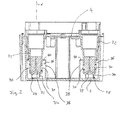
Die beispielhaft gezeigte Abwasserhebeanlage weist einen nach oben offenen Sammelbehälter 2 auf, dieser ist vorzugsweise als Formteil aus Kunststoff ausgebildet. An der Oberseite ist der Sammelbehälter 2 durch eine Flanschplatte 4 verschlossen, welche einen Deckel für den Sammelbehälter 2 bildet. Die Flanschplatte 4 trägt alle wesentlichen Komponenten der Abwasserhebeanlage. So trägt sie insbesondere ein Pumpenaggregat 6, mit einem oberhalb der Flanschplatte 4 angeordneten Elektromotor 8 und einer unterhalb der Flanschplatte 4 angeordneten Pumpe 10. Die Pumpe 10 ist dabei so angeordnet, dass sie in das Innere des Sammelbehälters 2 eintaucht und ihr Laufrad möglichst weit unten im Inneren des Sammelbehälters 2 gelegen ist. Darüber hinaus ist an der Flanschplatte 4 ein Schwimmerschalter 12 angeordnet, welcher zum Ein- und Ausschalten des Pumpenaggregates 6 dient. Der Schwimmerschalter 12 weist einen im Inneren des Sammelbehälters 2, d. h. unterhalb der Flanschplatte angeordneten Schwimmer 14 auf. Der Schwimmer 14 ist mittels einer Betätigungsstange 16 mit einem oberhalb der Flanschplatte 4 gelegenen elektrischen Schalter 18 verbunden. Wenn der Flüssigkeitsspiegel in dem Sammelbehälter 2 steigt, schwimmt der Schwimmer 14 nach oben und betätigt über die Betätigungsstange 16 den elektrischen Schalter 18 so, dass der Elektromotor 8 eingeschaltet und von diesem die Pumpe 10 angetrieben wird, sodass Flüssigkeit aus dem Sammelbehälter nach außen heraus gefördert wird. Wenn der Flüssigkeitsspiegel im Sammelbehälter 2 wieder sinkt, fällt auch der Schwimmer 14 nach unten und betätigt über die Betätigungsstange 16 den elektrischen Schalter 18 so, dass der Elektromotor 8 wieder ausgeschaltet wird.The wastewater lifting plant shown by way of example has an upwardly
Die Flanschplatte 4 weist an ihren vier Ecken jeweils ein sich vertikal nach unten erstreckendes Einlaufrohr 22 auf. Die Einlaufrohre 22 sind in diesem Fall einstückig mit der Flanschplatte 4 aus Kunststoff ausgebildet. In die obere Öffnung der Einlaufrohre 22 im Bereich der Flanschplatte 4 ist jeweils eine Dichtung 24 eingesetzt, welche zur Abdichtung eines eingesetzten Anschlussrohres 26 dient. Alle vier Einlaufrohre 22 sind gleich ausgebildet, und können wahlweise zum Anschluss eines Anschlussrohres 26 verwendet werden, je nachdem von welcher Richtung das Abwasser dem Sammelbehälter 2 zugeführt werden soll. Das Anschlussrohr 26 ist einfach von oben in das Einlaufrohr 22 eingesteckt und kommt dichtend am Innenumfang der Dichtung 24 zur Anlage. Mit ihrem Außenumfang liegt die Dichtung 24 dichtend am Innenumfang des Einlaufrohres 22 an.The
Die Einlaufrohre 22 sind in vertikaler Richtung X so lang ausgebildet, dass ihre unteren Enden 28 in vertikaler Richtung X von der Flanschplatte 4 weiter beabstandet sind als das untere Ende des Schwimmers 14. Auf diese Weise wird erreicht, dass dann, wenn die Flanschplatte 4 aus dem Sammelbehälter 2 entnommen und auf eine ebene Fläche abgestellt wird, die Flanschplatte 4 mit den angebrachten Komponenten, insbesondere dem Schwimmer 14 und der Pumpe 10 auf den unteren Enden 28 der Einlaufrohre 22 zu stehen kommt und der Schwimmer 14 idealer Weise nicht mit der Abstellfläche in Kontakt kommt. So wird eine Beschädigung des Schwimmers 14 oder des mit diesem über die Betätigungsstange 16 verbundenen elektrischen Schalters 18 beim Abstellen der Flanschplatte 4 verhindert.The
In dem gezeigten Beispiel sind die Einlaufrohre 22 nicht direkt an ihren unteren Enden 28 geöffnet sondern weisen radial gerichtete Austrittsöffnungen 30 auf, welche jeweils vom unteren Ende 28 vertikal nach oben beabstandet sind. So wird sichergestellt, dass die Austrittsöffnungen, durch welche Flüssigkeit bzw. Wasser in den Sammelbehälter 2 einströmt, nicht direkt am Boden des Sammelbehälters 2 gelegen sind, sodass sie nicht durch sich am Boden des Sammelbehälters 2 ansammelnde Verunreinigungen verstopfen können. Unterhalb der Austrittsöffnungen 30 weisen die Einlaufrohre 22 eine sich quer erstreckende geschlossene Stirnwand 32 auf, von welcher sich ein ringförmiges Fußelement 34 vertikal nach unten bis zum unteren Ende 28 erstreckt. Die Stirnwand 32 schließt jeweils den Strömungsweg bzw. -kanal im Inneren des Einlaufrohres 22 nach unten ab.In the example shown, the
Die Einlaufrohre 22 greifen mit ihrem unteren Ende und dem unteren Endabschnitt, in dem die Austrittsöffnungen 30 gelegen sind, jeweils in eine Einlaufkammer 36 ein. Die Einlaufkommern 36 sind in den Ecken des Sammelbehälters 2 durch Trennwände 38 gebildet, welche sich vom Boden des Sammelbehälters 2 vertikal nach oben erstrecken und an den Seitenwandungen des Sammelbehälters 2 anschließen. Die Trennwände 38 sind mit den Wandungen des Sammelbehälters 2 einstückig, vorzugsweise aus Kunststoff ausgebildet. So werden Einlaufkammern 36 gebildet, welche nur nach oben geöffnet sind, wobei das obere Ende 40 der Einlaufkommern 36 oberhalb der oberen Kante der Austrittsöffnungen 30 der Einlaufrohre 22 gelegen sind. Auf diese Weise wird eine Gassperre gebildet. Die Einlaufkammer 36 füllt sich zunächst mit Flüssigkeit bis zur Oberkante 40. Durch Überströmen der Oberkante 40 läuft die Flüssigkeit dann in den übrigen Bereich des Sammelbehälters 2, in dem der Schwimmer 14 und die Pumpe 10 angeordnet sind. So wird erreicht, dass die Austrittsöffnungen 30 des Einlaufrohres stets in der Flüssigkeit liegen, sodass kein Gas aus dem Einlaufrohr 22 in das Innere des Sammelbehälters 2 strömen kann. Sollte durch das Anschlussrohr 26 Gas in das Einlaufrohr 22 strömen, so kann dies durch eine Gasaustrittsöffnung 42 erfolgen, welche durch einen Spalt zwischen dem Außenumfang der Dichtung 24 und dem Innenumfang des Einlaufrohres 22 an dessen oberen Ende gebildet ist, erfolgen.The
Diese Ausgestaltung der Gassperre ist insbesondere dann von Vorteil, wenn die Abwasserhebeanlage, wie bei der gezeigten Abwasserhebeanlage vorgesehen, als Kondensathebeanlage in einer Heizungsanlage verwendet wird. Bei dieser Verwendung besteht die Gefahr, dass, insbesondere bei falscher Installation, Abgas aus der Heizungsanlage durch das Anschlussrohr 26 zu dem Sammelbehälter 2 strömt. Da dieses Abgas aggressive Stoffe enthält, soll das Abgas nicht in das Innere des Sammelbehälters 2 eintreten, was durch die beschriebene Gassperre, welche durch die Trennwand 38 gebildet wird, verhindert wird. Stattdessen wird das Abgas dann durch die Gasaustrittsöffnung 42 in die Umgebung abgeleitet.This embodiment of the gas barrier is particularly advantageous if the wastewater lifting plant, as provided in the sewage lifting plant shown, is used as a condensate lifting plant in a heating system. In this use, there is a risk that, in particular in case of incorrect installation, exhaust gas from the heating system flows through the connecting
Wie in
- 2 -2 -
- SammelbehälterClippings
- 4 -4 -
- Flanschplatteflange
- 6 -6 -
- Pumpenaggregatpump unit
- 8 -8th -
- Elektromotorelectric motor
- 10 -10 -
- Pumpepump
- 12 -12 -
- Niveau- bzw. SchwimmerschalterLevel or float switch
- 14 -14 -
- Schwimmerswimmer
- 16 -16 -
- Betätigungsstangeactuating rod
- 18 -18 -
- Elektrischer SchalterElectric switch
- 22 -22 -
- Einlaufrohrinlet pipe
- 24 -24 -
- Dichtungpoetry
- 26 -26 -
- Anschlussrohrconnecting pipe
- 28 -28 -
- Unteres Ende des EinlaufrohresLower end of the inlet pipe
- 30 -30 -
- Austrittsöffnungenoutlet openings
- 32 -32 -
- Stirnwandbulkhead
- 34 -34 -
- Fußelementfoot element
- 36 -36 -
- Einlaufkammerinlet chamber
- 38 -38 -
- Trennwändepartitions
- 40 -40 -
- Oberkantetop edge
- 42 -42 -
- GasaustrittsöffnungGas outlet
- 44 -44 -
- Öffnungopening
- 46 -46 -
- Öffnungopening
- 48 -48 -
- Öffnungopening
- X -X -
- vertikale Richtungvertical direction
Claims (12)
Priority Applications (3)
| Application Number | Priority Date | Filing Date | Title |
|---|---|---|---|
| EP20110182391 EP2573288B1 (en) | 2011-09-22 | 2011-09-22 | Waste water hoisting facility |
| US13/624,426 US9243395B2 (en) | 2011-09-22 | 2012-09-21 | Waste water lifting installation |
| CN201210355585.XA CN103015521B (en) | 2011-09-22 | 2012-09-21 | Waste water lifting installation |
Applications Claiming Priority (1)
| Application Number | Priority Date | Filing Date | Title |
|---|---|---|---|
| EP20110182391 EP2573288B1 (en) | 2011-09-22 | 2011-09-22 | Waste water hoisting facility |
Publications (2)
| Publication Number | Publication Date |
|---|---|
| EP2573288A1 true EP2573288A1 (en) | 2013-03-27 |
| EP2573288B1 EP2573288B1 (en) | 2013-10-16 |
Family
ID=44651513
Family Applications (1)
| Application Number | Title | Priority Date | Filing Date |
|---|---|---|---|
| EP20110182391 Active EP2573288B1 (en) | 2011-09-22 | 2011-09-22 | Waste water hoisting facility |
Country Status (3)
| Country | Link |
|---|---|
| US (1) | US9243395B2 (en) |
| EP (1) | EP2573288B1 (en) |
| CN (1) | CN103015521B (en) |
Cited By (1)
| Publication number | Priority date | Publication date | Assignee | Title |
|---|---|---|---|---|
| WO2017125294A1 (en) * | 2016-01-22 | 2017-07-27 | Ksb Aktiengesellschaft | Evacuation device |
Families Citing this family (2)
| Publication number | Priority date | Publication date | Assignee | Title |
|---|---|---|---|---|
| TWM482715U (en) * | 2014-03-31 | 2014-07-21 | Holimay Corp | Low noise drainage shell for air conditioning equipment drainage device |
| DE102018207243A1 (en) * | 2018-05-09 | 2019-11-14 | KSB SE & Co. KGaA | Sewage lifting unit |
Citations (2)
| Publication number | Priority date | Publication date | Assignee | Title |
|---|---|---|---|---|
| DE3113903A1 (en) * | 1981-04-07 | 1982-10-21 | Werner Dipl.-Ing. 2800 Bremen Fass | Apparatus for the vacuum suction removal of liquids |
| US20060228222A1 (en) * | 2005-03-29 | 2006-10-12 | Pohler Donald M | Sewage handling system, cover, and controls |
Family Cites Families (8)
| Publication number | Priority date | Publication date | Assignee | Title |
|---|---|---|---|---|
| US5103793A (en) * | 1991-01-15 | 1992-04-14 | Brunswick Corporation | Vapor separator for an internal combustion engine |
| JP3751334B2 (en) * | 1995-04-05 | 2006-03-01 | 株式会社鶴見製作所 | Waste water discharge device |
| US6322326B1 (en) * | 1999-01-29 | 2001-11-27 | Lee W. Davis | Modular condensate pump assembly |
| CN2396117Y (en) * | 1999-11-01 | 2000-09-13 | 祝丹 | Sealed sewage lifting and delivering device |
| JP2002285635A (en) * | 2001-03-24 | 2002-10-03 | Akiharu Enami | Sewage suction-discharge device equipped with cushion tank |
| US20070224050A1 (en) * | 2006-03-24 | 2007-09-27 | Ward Charles B | Condensate pump |
| CN201850629U (en) * | 2010-10-30 | 2011-06-01 | 中冶北方工程技术有限公司 | Anti-precipitate sewage discharge device |
| CN201981644U (en) * | 2011-02-11 | 2011-09-21 | 万若(北京)环境工程技术有限公司 | Secondary vacuum lifting device |
-
2011
- 2011-09-22 EP EP20110182391 patent/EP2573288B1/en active Active
-
2012
- 2012-09-21 US US13/624,426 patent/US9243395B2/en active Active
- 2012-09-21 CN CN201210355585.XA patent/CN103015521B/en not_active Expired - Fee Related
Patent Citations (2)
| Publication number | Priority date | Publication date | Assignee | Title |
|---|---|---|---|---|
| DE3113903A1 (en) * | 1981-04-07 | 1982-10-21 | Werner Dipl.-Ing. 2800 Bremen Fass | Apparatus for the vacuum suction removal of liquids |
| US20060228222A1 (en) * | 2005-03-29 | 2006-10-12 | Pohler Donald M | Sewage handling system, cover, and controls |
Cited By (1)
| Publication number | Priority date | Publication date | Assignee | Title |
|---|---|---|---|---|
| WO2017125294A1 (en) * | 2016-01-22 | 2017-07-27 | Ksb Aktiengesellschaft | Evacuation device |
Also Published As
| Publication number | Publication date |
|---|---|
| EP2573288B1 (en) | 2013-10-16 |
| CN103015521B (en) | 2015-05-20 |
| US20130074950A1 (en) | 2013-03-28 |
| US9243395B2 (en) | 2016-01-26 |
| CN103015521A (en) | 2013-04-03 |
Similar Documents
| Publication | Publication Date | Title |
|---|---|---|
| EP2573288B1 (en) | Waste water hoisting facility | |
| EP1775395B1 (en) | Draining device for sanitary installations | |
| DE102010053588B4 (en) | Gärsaftabscheider | |
| EP1422354B1 (en) | Odour seal | |
| EP2489801A1 (en) | Waste water hoisting facility | |
| EP3364043B1 (en) | Pump unit with integrated air venting and liquid purge device | |
| EP1127988B1 (en) | Gulley with float closure | |
| DE102011107817A1 (en) | Device for pumping liquids, has liquid pump which pumps liquid from area over one or more tubes or channels, where control unit is provided with pressure switch | |
| DE10361532B3 (en) | Control valve with sand and leaf trap for drain in street or roadway has air access openings in sides of housing and float closing air valve when valve chamber is full of water | |
| DE3333883A1 (en) | Tank for a sewage pumping station | |
| WO2010022704A2 (en) | Cistern with a rainwater filter in the inflow, and a filter housing for a rainwater filter | |
| DE102011013349A1 (en) | Discharge device e.g. floor drain for waste water used in e.g. bathroom, has sealing unit that is in contact with the drain port of trap | |
| DE102012110773B4 (en) | Pumping station and process for pumping wastewater | |
| EP2154300B1 (en) | Waste water station | |
| EP2365140A2 (en) | Filter device for roof drain systems | |
| DE102010044940A1 (en) | Sewage water outlet port for use with stench trap for flattened shower bath, has collection channel whose outer side is limited by housing side wall, where collection channel is drained by lateral discharge opening | |
| CH658088A5 (en) | WASTEWATER DRAIN, CONSISING OF A DRAINAGE TANK WITH AT LEAST ONE INLET AND DRAIN PIPE AND USE THEREOF. | |
| EP2573284B1 (en) | Waste water hoisting facility | |
| EP2776640B1 (en) | Floor drain device | |
| EP2573482A1 (en) | Condensate lifting assembly | |
| EP3421676B1 (en) | Odour seal element for installation in a drain, in particular the drain of a waterless urinal | |
| DE102010038298A1 (en) | Separator or fat separator useful for separating water from hydrophobic substances, preferably lipophilic substances e.g. fats, comprises a separation container with inlet for hydrophobic substances-containing water, and damming device | |
| EP2106731B1 (en) | Dish washer | |
| DE202008015411U1 (en) | Drip container | |
| DE102007023892A1 (en) | Device for draining water in form of water leaking through damaged joints on periphery of shower tray has reverse flow inhibitor between leakage water outlet opening and leakage water connection of siphon |
Legal Events
| Date | Code | Title | Description |
|---|---|---|---|
| PUAI | Public reference made under article 153(3) epc to a published international application that has entered the european phase |
Free format text: ORIGINAL CODE: 0009012 |
|
| AK | Designated contracting states |
Kind code of ref document: A1 Designated state(s): AL AT BE BG CH CY CZ DE DK EE ES FI FR GB GR HR HU IE IS IT LI LT LU LV MC MK MT NL NO PL PT RO RS SE SI SK SM TR |
|
| AX | Request for extension of the european patent |
Extension state: BA ME |
|
| 17P | Request for examination filed |
Effective date: 20130315 |
|
| GRAP | Despatch of communication of intention to grant a patent |
Free format text: ORIGINAL CODE: EPIDOSNIGR1 |
|
| RIC1 | Information provided on ipc code assigned before grant |
Ipc: E03F 5/22 20060101AFI20130408BHEP |
|
| INTG | Intention to grant announced |
Effective date: 20130502 |
|
| GRAS | Grant fee paid |
Free format text: ORIGINAL CODE: EPIDOSNIGR3 |
|
| GRAA | (expected) grant |
Free format text: ORIGINAL CODE: 0009210 |
|
| AK | Designated contracting states |
Kind code of ref document: B1 Designated state(s): AL AT BE BG CH CY CZ DE DK EE ES FI FR GB GR HR HU IE IS IT LI LT LU LV MC MK MT NL NO PL PT RO RS SE SI SK SM TR |
|
| REG | Reference to a national code |
Ref country code: GB Ref legal event code: FG4D Free format text: NOT ENGLISH |
|
| REG | Reference to a national code |
Ref country code: CH Ref legal event code: EP |
|
| REG | Reference to a national code |
Ref country code: IE Ref legal event code: FG4D Free format text: LANGUAGE OF EP DOCUMENT: GERMAN |
|
| REG | Reference to a national code |
Ref country code: AT Ref legal event code: REF Ref document number: 636603 Country of ref document: AT Kind code of ref document: T Effective date: 20131115 |
|
| REG | Reference to a national code |
Ref country code: DE Ref legal event code: R096 Ref document number: 502011001488 Country of ref document: DE Effective date: 20131212 |
|
| REG | Reference to a national code |
Ref country code: NL Ref legal event code: VDEP Effective date: 20131016 |
|
| REG | Reference to a national code |
Ref country code: LT Ref legal event code: MG4D |
|
| PG25 | Lapsed in a contracting state [announced via postgrant information from national office to epo] |
Ref country code: FI Free format text: LAPSE BECAUSE OF FAILURE TO SUBMIT A TRANSLATION OF THE DESCRIPTION OR TO PAY THE FEE WITHIN THE PRESCRIBED TIME-LIMIT Effective date: 20131016 Ref country code: NL Free format text: LAPSE BECAUSE OF FAILURE TO SUBMIT A TRANSLATION OF THE DESCRIPTION OR TO PAY THE FEE WITHIN THE PRESCRIBED TIME-LIMIT Effective date: 20131016 Ref country code: HR Free format text: LAPSE BECAUSE OF FAILURE TO SUBMIT A TRANSLATION OF THE DESCRIPTION OR TO PAY THE FEE WITHIN THE PRESCRIBED TIME-LIMIT Effective date: 20131016 Ref country code: LT Free format text: LAPSE BECAUSE OF FAILURE TO SUBMIT A TRANSLATION OF THE DESCRIPTION OR TO PAY THE FEE WITHIN THE PRESCRIBED TIME-LIMIT Effective date: 20131016 Ref country code: NO Free format text: LAPSE BECAUSE OF FAILURE TO SUBMIT A TRANSLATION OF THE DESCRIPTION OR TO PAY THE FEE WITHIN THE PRESCRIBED TIME-LIMIT Effective date: 20140116 Ref country code: SE Free format text: LAPSE BECAUSE OF FAILURE TO SUBMIT A TRANSLATION OF THE DESCRIPTION OR TO PAY THE FEE WITHIN THE PRESCRIBED TIME-LIMIT Effective date: 20131016 Ref country code: IS Free format text: LAPSE BECAUSE OF FAILURE TO SUBMIT A TRANSLATION OF THE DESCRIPTION OR TO PAY THE FEE WITHIN THE PRESCRIBED TIME-LIMIT Effective date: 20140216 |
|
| PG25 | Lapsed in a contracting state [announced via postgrant information from national office to epo] |
Ref country code: RS Free format text: LAPSE BECAUSE OF FAILURE TO SUBMIT A TRANSLATION OF THE DESCRIPTION OR TO PAY THE FEE WITHIN THE PRESCRIBED TIME-LIMIT Effective date: 20131016 Ref country code: LV Free format text: LAPSE BECAUSE OF FAILURE TO SUBMIT A TRANSLATION OF THE DESCRIPTION OR TO PAY THE FEE WITHIN THE PRESCRIBED TIME-LIMIT Effective date: 20131016 Ref country code: ES Free format text: LAPSE BECAUSE OF FAILURE TO SUBMIT A TRANSLATION OF THE DESCRIPTION OR TO PAY THE FEE WITHIN THE PRESCRIBED TIME-LIMIT Effective date: 20131016 Ref country code: CY Free format text: LAPSE BECAUSE OF FAILURE TO SUBMIT A TRANSLATION OF THE DESCRIPTION OR TO PAY THE FEE WITHIN THE PRESCRIBED TIME-LIMIT Effective date: 20131016 |
|
| PG25 | Lapsed in a contracting state [announced via postgrant information from national office to epo] |
Ref country code: PT Free format text: LAPSE BECAUSE OF FAILURE TO SUBMIT A TRANSLATION OF THE DESCRIPTION OR TO PAY THE FEE WITHIN THE PRESCRIBED TIME-LIMIT Effective date: 20140217 |
|
| REG | Reference to a national code |
Ref country code: DE Ref legal event code: R097 Ref document number: 502011001488 Country of ref document: DE |
|
| PG25 | Lapsed in a contracting state [announced via postgrant information from national office to epo] |
Ref country code: EE Free format text: LAPSE BECAUSE OF FAILURE TO SUBMIT A TRANSLATION OF THE DESCRIPTION OR TO PAY THE FEE WITHIN THE PRESCRIBED TIME-LIMIT Effective date: 20131016 |
|
| PLBE | No opposition filed within time limit |
Free format text: ORIGINAL CODE: 0009261 |
|
| STAA | Information on the status of an ep patent application or granted ep patent |
Free format text: STATUS: NO OPPOSITION FILED WITHIN TIME LIMIT |
|
| PG25 | Lapsed in a contracting state [announced via postgrant information from national office to epo] |
Ref country code: PL Free format text: LAPSE BECAUSE OF FAILURE TO SUBMIT A TRANSLATION OF THE DESCRIPTION OR TO PAY THE FEE WITHIN THE PRESCRIBED TIME-LIMIT Effective date: 20131016 Ref country code: RO Free format text: LAPSE BECAUSE OF FAILURE TO SUBMIT A TRANSLATION OF THE DESCRIPTION OR TO PAY THE FEE WITHIN THE PRESCRIBED TIME-LIMIT Effective date: 20131016 Ref country code: IT Free format text: LAPSE BECAUSE OF FAILURE TO SUBMIT A TRANSLATION OF THE DESCRIPTION OR TO PAY THE FEE WITHIN THE PRESCRIBED TIME-LIMIT Effective date: 20131016 Ref country code: CZ Free format text: LAPSE BECAUSE OF FAILURE TO SUBMIT A TRANSLATION OF THE DESCRIPTION OR TO PAY THE FEE WITHIN THE PRESCRIBED TIME-LIMIT Effective date: 20131016 Ref country code: SK Free format text: LAPSE BECAUSE OF FAILURE TO SUBMIT A TRANSLATION OF THE DESCRIPTION OR TO PAY THE FEE WITHIN THE PRESCRIBED TIME-LIMIT Effective date: 20131016 |
|
| 26N | No opposition filed |
Effective date: 20140717 |
|
| PG25 | Lapsed in a contracting state [announced via postgrant information from national office to epo] |
Ref country code: DK Free format text: LAPSE BECAUSE OF FAILURE TO SUBMIT A TRANSLATION OF THE DESCRIPTION OR TO PAY THE FEE WITHIN THE PRESCRIBED TIME-LIMIT Effective date: 20131016 |
|
| REG | Reference to a national code |
Ref country code: DE Ref legal event code: R097 Ref document number: 502011001488 Country of ref document: DE Effective date: 20140717 |
|
| PG25 | Lapsed in a contracting state [announced via postgrant information from national office to epo] |
Ref country code: SI Free format text: LAPSE BECAUSE OF FAILURE TO SUBMIT A TRANSLATION OF THE DESCRIPTION OR TO PAY THE FEE WITHIN THE PRESCRIBED TIME-LIMIT Effective date: 20131016 |
|
| PG25 | Lapsed in a contracting state [announced via postgrant information from national office to epo] |
Ref country code: MC Free format text: LAPSE BECAUSE OF FAILURE TO SUBMIT A TRANSLATION OF THE DESCRIPTION OR TO PAY THE FEE WITHIN THE PRESCRIBED TIME-LIMIT Effective date: 20131016 Ref country code: LU Free format text: LAPSE BECAUSE OF FAILURE TO SUBMIT A TRANSLATION OF THE DESCRIPTION OR TO PAY THE FEE WITHIN THE PRESCRIBED TIME-LIMIT Effective date: 20140922 |
|
| REG | Reference to a national code |
Ref country code: CH Ref legal event code: PL |
|
| REG | Reference to a national code |
Ref country code: IE Ref legal event code: MM4A |
|
| PG25 | Lapsed in a contracting state [announced via postgrant information from national office to epo] |
Ref country code: BE Free format text: LAPSE BECAUSE OF NON-PAYMENT OF DUE FEES Effective date: 20140930 |
|
| PG25 | Lapsed in a contracting state [announced via postgrant information from national office to epo] |
Ref country code: LI Free format text: LAPSE BECAUSE OF NON-PAYMENT OF DUE FEES Effective date: 20140930 Ref country code: CH Free format text: LAPSE BECAUSE OF NON-PAYMENT OF DUE FEES Effective date: 20140930 |
|
| PG25 | Lapsed in a contracting state [announced via postgrant information from national office to epo] |
Ref country code: IE Free format text: LAPSE BECAUSE OF NON-PAYMENT OF DUE FEES Effective date: 20140922 |
|
| PG25 | Lapsed in a contracting state [announced via postgrant information from national office to epo] |
Ref country code: SM Free format text: LAPSE BECAUSE OF FAILURE TO SUBMIT A TRANSLATION OF THE DESCRIPTION OR TO PAY THE FEE WITHIN THE PRESCRIBED TIME-LIMIT Effective date: 20131016 |
|
| PG25 | Lapsed in a contracting state [announced via postgrant information from national office to epo] |
Ref country code: GR Free format text: LAPSE BECAUSE OF FAILURE TO SUBMIT A TRANSLATION OF THE DESCRIPTION OR TO PAY THE FEE WITHIN THE PRESCRIBED TIME-LIMIT Effective date: 20140117 Ref country code: BG Free format text: LAPSE BECAUSE OF FAILURE TO SUBMIT A TRANSLATION OF THE DESCRIPTION OR TO PAY THE FEE WITHIN THE PRESCRIBED TIME-LIMIT Effective date: 20131016 Ref country code: MT Free format text: LAPSE BECAUSE OF FAILURE TO SUBMIT A TRANSLATION OF THE DESCRIPTION OR TO PAY THE FEE WITHIN THE PRESCRIBED TIME-LIMIT Effective date: 20131016 |
|
| REG | Reference to a national code |
Ref country code: FR Ref legal event code: PLFP Year of fee payment: 6 |
|
| PG25 | Lapsed in a contracting state [announced via postgrant information from national office to epo] |
Ref country code: TR Free format text: LAPSE BECAUSE OF FAILURE TO SUBMIT A TRANSLATION OF THE DESCRIPTION OR TO PAY THE FEE WITHIN THE PRESCRIBED TIME-LIMIT Effective date: 20131016 Ref country code: HU Free format text: LAPSE BECAUSE OF FAILURE TO SUBMIT A TRANSLATION OF THE DESCRIPTION OR TO PAY THE FEE WITHIN THE PRESCRIBED TIME-LIMIT; INVALID AB INITIO Effective date: 20110922 |
|
| REG | Reference to a national code |
Ref country code: FR Ref legal event code: PLFP Year of fee payment: 7 |
|
| REG | Reference to a national code |
Ref country code: AT Ref legal event code: MM01 Ref document number: 636603 Country of ref document: AT Kind code of ref document: T Effective date: 20160922 |
|
| PG25 | Lapsed in a contracting state [announced via postgrant information from national office to epo] |
Ref country code: AT Free format text: LAPSE BECAUSE OF NON-PAYMENT OF DUE FEES Effective date: 20160922 |
|
| PG25 | Lapsed in a contracting state [announced via postgrant information from national office to epo] |
Ref country code: MK Free format text: LAPSE BECAUSE OF FAILURE TO SUBMIT A TRANSLATION OF THE DESCRIPTION OR TO PAY THE FEE WITHIN THE PRESCRIBED TIME-LIMIT Effective date: 20131016 |
|
| REG | Reference to a national code |
Ref country code: FR Ref legal event code: PLFP Year of fee payment: 8 |
|
| PG25 | Lapsed in a contracting state [announced via postgrant information from national office to epo] |
Ref country code: AL Free format text: LAPSE BECAUSE OF FAILURE TO SUBMIT A TRANSLATION OF THE DESCRIPTION OR TO PAY THE FEE WITHIN THE PRESCRIBED TIME-LIMIT Effective date: 20131016 |
|
| REG | Reference to a national code |
Ref country code: DE Ref legal event code: R082 Ref document number: 502011001488 Country of ref document: DE |
|
| PGFP | Annual fee paid to national office [announced via postgrant information from national office to epo] |
Ref country code: GB Payment date: 20230920 Year of fee payment: 13 |
|
| PGFP | Annual fee paid to national office [announced via postgrant information from national office to epo] |
Ref country code: FR Payment date: 20230928 Year of fee payment: 13 Ref country code: DE Payment date: 20230920 Year of fee payment: 13 |