EP2573285A1 - Abwasserhebeanlage - Google Patents
Abwasserhebeanlage Download PDFInfo
- Publication number
- EP2573285A1 EP2573285A1 EP11182386A EP11182386A EP2573285A1 EP 2573285 A1 EP2573285 A1 EP 2573285A1 EP 11182386 A EP11182386 A EP 11182386A EP 11182386 A EP11182386 A EP 11182386A EP 2573285 A1 EP2573285 A1 EP 2573285A1
- Authority
- EP
- European Patent Office
- Prior art keywords
- collecting container
- wall
- plant according
- lifting plant
- holding elements
- Prior art date
- Legal status (The legal status is an assumption and is not a legal conclusion. Google has not performed a legal analysis and makes no representation as to the accuracy of the status listed.)
- Granted
Links
- 239000002351 wastewater Substances 0.000 title claims description 20
- 239000010865 sewage Substances 0.000 claims description 24
- 238000010438 heat treatment Methods 0.000 claims description 4
- 238000004378 air conditioning Methods 0.000 claims description 2
- 238000006073 displacement reaction Methods 0.000 description 4
- 239000007788 liquid Substances 0.000 description 4
- 241000238633 Odonata Species 0.000 description 3
- XLYOFNOQVPJJNP-UHFFFAOYSA-N water Substances O XLYOFNOQVPJJNP-UHFFFAOYSA-N 0.000 description 3
- 238000002347 injection Methods 0.000 description 2
- 239000007924 injection Substances 0.000 description 2
- 230000000694 effects Effects 0.000 description 1
- 239000012530 fluid Substances 0.000 description 1
- 238000007373 indentation Methods 0.000 description 1
Images


Classifications
-
- E—FIXED CONSTRUCTIONS
- E03—WATER SUPPLY; SEWERAGE
- E03F—SEWERS; CESSPOOLS
- E03F5/00—Sewerage structures
- E03F5/22—Adaptations of pumping plants for lifting sewage
-
- F—MECHANICAL ENGINEERING; LIGHTING; HEATING; WEAPONS; BLASTING
- F04—POSITIVE - DISPLACEMENT MACHINES FOR LIQUIDS; PUMPS FOR LIQUIDS OR ELASTIC FLUIDS
- F04D—NON-POSITIVE-DISPLACEMENT PUMPS
- F04D15/00—Control, e.g. regulation, of pumps, pumping installations or systems
- F04D15/02—Stopping of pumps, or operating valves, on occurrence of unwanted conditions
- F04D15/0209—Stopping of pumps, or operating valves, on occurrence of unwanted conditions responsive to a condition of the working fluid
- F04D15/0218—Stopping of pumps, or operating valves, on occurrence of unwanted conditions responsive to a condition of the working fluid the condition being a liquid level or a lack of liquid supply
Definitions
- the invention relates to a wastewater lifting plant with the features specified in the preamble of claim 1.
- Wastewater lifting plants are used to raise and / or pump effluents, which are at a level below a sewer or sewer, to the level of the sewer.
- Such sewage lifting systems are known, for example, to pump condensate from heating systems in higher-lying sewers.
- Such sewage lifting plants usually have a collecting container in which a pump unit is arranged. The to be pumped or lifted wastewater flows into the sump.
- the pump unit is switched on via a level switch, for example a float switch, and the water or liquid is pumped out of the collecting container. If the fluid level in the reservoir returns to a predetermined lower level, the pump set is switched off again.
- the wastewater lifting plant according to the invention like known sewage lifting plants, has a collecting tank and at least one pump unit arranged on or in the collecting tank.
- the collecting container is designed so that liquid to be lifted or effluent to be discharged can flow into it.
- at least one inlet opening can be provided.
- the pump unit is designed to pump wastewater from the sump in a subsequent- ⁇ ende output line and through this in a higher-lying sewer.
- a level switch such as a float switch in the reservoir.
- the collecting container has, on at least one side wall, fastening means which are designed to fasten the collecting container to a wall.
- the fastening means are designed such that they have two horizontally spaced-apart holding elements in the upper region of the side wall. These holding elements are designed for connection to receiving elements mounted on the wall in each case.
- the holding elements may be formed so that they screwed into the wall screw or behind a hook.
- the holding elements are preferably arranged in the upper region of the side wall, in particular in the region of the upper half, more preferably in the region of the upper third of the side wall of the collecting container.
- the fastening means additionally have a supporting element.
- This is arranged vertically below the retaining elements.
- the holding element is thus located in the lower region of the side wall of the collecting container, in particular in the lower half of the side wall, more preferably in the lower third of the side wall.
- the support element is arranged in the horizontal direction between the two holding elements, preferably in the middle between the holding elements.
- the support element is designed so that it can be supported on a wall, d. H. can come to plant on a wall and so can support the sump against the wall. About the support element, the distance of the lower end of the collecting container can be adjusted from the wall.
- the lower end of the collecting container can be further pushed away from the wall, by a shorter support member, the lower end of the side wall comes closer to the wall to which the collecting container is attached to lie. In this way, it is possible to horizontally align the sump in a direction transverse to the wall to which it is attached.
- the support element preferably has a supporting surface provided for bearing on the wall, the distance of which from the side wall of the collecting container being adjustable.
- the distance of which from the side wall of the collecting container being adjustable.
- the support element has a with its axis of rotation transverse to the side wall extending adjusting screw.
- the support element can be extended and shortened in the direction transverse to the wall.
- a section of the set screw screws into or out of a counterpart.
- This counterpart is preferably mounted on the side wall of the collecting container.
- the support element itself may be telescopically formed, that is to say formed from two sections, one with an internal thread and one with an external thread, wherein the section with the external thread can be screwed into the section with the internal thread and unscrewed to the length of To vary support element.
- the adjusting screw is engaged with a first axial end with a thread formed on the collecting container and a second, opposite axial end of the adjusting screw forms the supporting surface for engagement with the wall.
- the thread is preferably formed directly in the side wall of the collecting container or as a threaded insert. This is particularly useful when the collection container is made of plastic as an injection molded part. Then such a thread can easily form directly in the side wall or pour a threaded insert. In this case, however, thread and side wall are formed so that the thread does not form an opening to the interior of the collecting container, so that it is open towards the bottom and preferably only to the top.
- the thread on the collecting container is preferably formed as an internal thread, in which engages the screw with an external thread.
- a threaded bolt is attached to the side wall, that it extends transversely away from the side wall.
- a support element can then be screwed, which has a corresponding internal thread.
- the threaded bolt engages in the internal thread results in a different length of the entire support element.
- an internal thread is formed on the side wall, then this is formed so long that there is sufficient adjustment by screwing in and out of the adjusting screw. That is, the internal thread must be so long that it can accommodate a sufficient length of the screw to shorten the support in the desired manner.
- a sufficiently long receiving space can be provided behind the internal thread, in which the adjusting screw can engage.
- the adjusting screw has an enlarged diameter diameter adjusting wheel which is rotatably connected to the adjusting screw, preferably integrally formed therewith.
- set screw and thumbwheel can be integrally formed of plastic.
- the thumbwheel makes it easier to grasp the set screw so that it rotates, making it easier to adjust.
- the thumbwheel is structured on its outer circumference, for example, corrugated, so that it can be easily grasped.
- the thumbwheel on such a large diameter that the thumbwheel over a lower edge of the side wall of the collecting container protrudes. That is, the radius of the adjusting wheel is greater than the distance of the axis of rotation of the adjusting screw from the lower edge of the side wall.
- the lower edge of the side wall preferably also forms the lower edge of the collecting container.
- the screw is at the bottom of the collecting container with its thumbwheel, so that the wheel can be easily gripped from the bottom, even if the sump on the wall hangs.
- a slight adjustment of the screw is possible to align the sump horizontally in a direction transverse to the wall.
- a support element which, as described above, is preferably designed as a set screw and the two holding elements created a three-point system.
- This three-point system has the advantage that the orientation of the collecting container in a direction transverse to the wall to which the collecting container is attached, is very simple, since only one support element must be adjusted or adjusted for this orientation. The arrangement of a single support element thus simplifies the alignment quite considerably.
- the two holding elements are further preferably designed such that they each allow a vertical adjustment of the position of the collecting container relative to a receiving element mounted on a wall. Ie. the holding elements make it possible to adjust the collecting container at the position of the holding element up and down. In this way, a horizontal alignment in the direction parallel to the wall is possible.
- the holding elements are preferably designed so that they each have an inclined to the horizontal extending downwardly directed support surface.
- the holding elements With this bearing surface, the holding elements is located on a screw or a hook which forms the receiving element on or in the wall.
- This receiving surface is inclined to the horizontal, it comes with a displacement of the collecting container in the horizontal direction parallel to the wall to a lifting or lowering, depending on the direction of displacement.
- the horizontal, to which the bearing surfaces are inclined is an axis or line of the collecting container or the wastewater lifting plant, which extends horizontally with correct positioning of the sewage lifting plant.
- the two holding elements are inclined in the opposite direction.
- bearing surfaces each rest on a receiving element, this has the effect that, in the case of a horizontal displacement on the one holding element, a displacement of the sewage lifting device upwards and simultaneously on the other holding element comes to a downward shift.
- the bearing surfaces need not be straight, but may also be curved, that is, for example, be formed concave or convex curved.
- the bearing surfaces are preferably structured and in particular toothed. This embodiment prevents slippage of the bearing surfaces of the receiving elements, in particular screws or hooks on the wall.
- the screws or hooks come to lie in a tooth gap, so that the support surface can not be moved unintentionally in a direction parallel to the wall on the receiving element or can slip.
- both holding elements are formed integrally with the side wall of the collecting container.
- the holding elements are formed on a rear side wall of the collecting container.
- the holding elements preferably have receiving surfaces which are spaced from the side wall, so that the holding elements of screw heads or hooks can be engaged behind and come to rest with the bearing surfaces on the screws or hooks.
- the holding elements may have a second wall spaced from the side wall, which forms the bearing surface on its underside and forms a gap between the side wall and this wall, in which a hook or screw head can engage.
- a one-piece design of the retaining elements on the side wall of the collecting container lends itself to when this is made as an injection molded part made of plastic.
- the collecting container may have on its underside feet for setting up the collecting container. These feet can be detachable, so that they can be removed when the container is hung on a wall.
- the additional or optional attachment of feet has the advantage that the sump and thus the entire sewage lifting system can be set up as an alternative to the described wall mounting on the floor or other footprint.
- the wastewater lifting plant is designed as a condensate lifting plant, in particular for use in a heating or air conditioning.
- the wastewater lifting plant has a collecting container 2, which forms the lower part of the wastewater lifting plant.
- the sump 2 has a bottom 6 of substantially rectangular shape, from which four side walls 8 extend substantially vertically upward at the side edges.
- the collecting container 2 is designed to be open and is closed by a cover 10.
- a pump unit 12 is attached on the cover 10.
- the pump unit has an arranged below the lid 10 in the interior of the collecting container 2 pump 14 and an above the lid 10 arranged electric motor 16 which drives the pump 14 via a shaft not shown here.
- the pump 14 delivers water from the reservoir 2 in an outlet line 18.
- a arranged in the reservoir 2 float switch 20 is provided which the electric motor 16 in dependence of the liquid level inside of the collection container 2 turns on and off.
- the wastewater lifting plant is aligned horizontally with its collecting container 2, so that the bottom 6 of the collecting container 2 extends substantially horizontally in two directions. This can be done either by placing the collecting container with the feet 22 on a flat and level floor or by attachment to the wall.
- the fastening means have two holding elements 24 located in the upper region of the side wall 8, that is to say in the upper third of the side wall 8.
- the two holding elements 24 are spaced apart in the horizontal direction, so that they are located near the side edges of the side wall 8.
- the holding elements are each formed by a wall 26 which extends substantially parallel to the side wall 8 on the outside thereof.
- the lower edge of this wall 26 is formed in each case as a support surface 28.
- the support surfaces 28 are formed toothed and extend inclined to the horizontal H, that is inclined to the bottom 6, which should extend horizontally with the correct orientation of the sump.
- the support surfaces 28 are inclined in opposite directions to the horizontal H, so seen in the horizontal direction H, the inner ends of the support surfaces 28 are located vertically higher than the outer ends.
- the bearing surfaces 28 serve to come to rest on a receiving element in the wall.
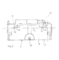
- the recording elements are as in Fig. 3 shown, screws 30 which are fixed in the wall 32.
- the screws 30 engage behind the walls 26 with their screw heads, so that the screw heads come to lie with their edges between the walls 26 and the side wall 8. In this way it is prevented that the collecting container can slip off the screws to the front.
- the fastening means have a third element, namely a support element in the form of a set screw 34.
- the adjusting screw 34 engages with its first axial end 36 in an internal thread 38 a.
- the internal thread 38 is formed in a threaded bush or nut, which is fastened or cast in the lower region of the side wall 8.
- the opposite second axial end 42 of the screw 34 forms a support surface or a support point 42, which comes to rest on the wall 32 and is supported there. In this way, the entire collecting container 2 is supported at its lower end on the wall 32.
- the internal thread 38 is formed in the region of the lower third of the rear side wall 8 of the collecting container 2, that is vertically spaced down from the holding elements 24 and their contact surfaces 28.
- the internal thread 8 in the horizontal center of the rear side wall eighth that is located centrally between the two holding elements 24. This is how a three-point system is created.
- the horizontal alignment via the inclined configuration of the contact surfaces 28, the horizontal alignment in the direction parallel to the wall 32.
- the screw 34 By turning the screw 34, the horizontal alignment takes place in the direction transverse to the wall 32.
- the distance between the wall 32 and the side wall 8 increases at the lower end of the collecting container 2. If the adjusting screw 34 screwed further into the internal thread 38, correspondingly reduces the distance.
- the collecting container 2 tilts about the contact points of the contact surfaces 28 on the screws 30th
- a thumbwheel 44 In order to enable a simple turning of the adjusting screw 34, this is provided with a thumbwheel 44.
- the thumbwheel 44 has a larger diameter than the adjusting screw 34 and can therefore be better taken.
- the diameter of the setting wheel 44 is so large that its radius R is greater than the vertical distance a of the axis of rotation of the adjusting screw 34 from the bottom of the bottom 6.
- the thumbwheel 44 is down over the bottom of the bottom 6 before and can so even then easily taken and turned when the sump 2 already rests on the screws 30.
- the alignment can be done by rotating the adjusting wheel 44 after hanging the collecting container 2 on the wall 32.
- dragonflies can be arranged in the manner of spirit levels.
Landscapes
- Engineering & Computer Science (AREA)
- Mechanical Engineering (AREA)
- General Engineering & Computer Science (AREA)
- Health & Medical Sciences (AREA)
- Life Sciences & Earth Sciences (AREA)
- Hydrology & Water Resources (AREA)
- Public Health (AREA)
- Water Supply & Treatment (AREA)
- Cultivation Receptacles Or Flower-Pots, Or Pots For Seedlings (AREA)
- Sewage (AREA)
Abstract
Description
- Die Erfindung betrifft eine Abwasserhebeanlage mit den im Oberbegriff des Anspruchs 1 angegebenen Merkmalen.
- Abwasserhebeanlagen werden verwendet, um Abwässer, welche auf einem Niveau unterhalb einer Abwasserleitung oder Kanalisation anfallen, auf das Niveau der Abwasserleitung bzw. Kanalisation zu heben bzw. zu pumpen. Derartige Abwasserhebeanlagen sind beispielsweise bekannt, um Kondensat aus Heizungsanlagen in höher gelegene Abwasserleitungen zu pumpen. Solche Abwasserhebeanlagen weisen meist einen Sammelbehälter auf, in welchem ein Pumpenaggregat angeordnet ist. Das zu fördernde bzw. zu hebende Abwasser fließt in den Sammelbehälter ein. Wenn der Wasserstand in dem Sammelbehälter ein vorbestimmtes Niveau erreicht hat, wird über einen Niveauschalter, beispielsweise einen Schwimmerschalter das Pumpenaggregat eingeschaltet und das Wasser bzw. die Flüssigkeit aus dem Sammelbehälter herausgepumpt. Fällt der Flüssigkeitsstand in dem Sammelbehälter wieder auf ein vorbestimmtes niedrigeres Niveau, wird das Pumpenaggregat wieder abgeschaltet. Es ist bekannt, diese Abwasserhebeanlagen so auszubilden, dass sie mit ihrem Sammelbehälter an einer Wand befestigt werden können. Bei dieser Befestigung ist es wichtig, dass die Abwasserhebeanlage und insbesondere deren Sammelbehälter richtig in zwei Richtungen horizontal ausgerichtet wird, damit Pumpenaggregat und Niveauschalter im Inneren in der gewünschten Weise funktionieren. Da die Wände, an welchen derartige Abwasserhebeanlagen befestigt werden, nicht immer gerade sind, ist die Ausrichtung des Sammelbehälters in zwei Richtungen oft schwierig.
- Im Hinblick auf diese Problematik ist es Aufgabe der Erfindung, eine verbesserte Abwasserhebeanlage bereitzustellen, welche bei Befestigung an einer Wand eine einfache Ausrichtung ihres Sammelbehälters in zwei Richtungen ermöglicht.
- Diese Aufgabe wird durch eine Abwasserhebeanlage mit den in Anspruch 1 angegebenen Merkmalen gelöst. Bevorzugte Ausführungsformen ergeben sich aus den Unteransprüchen, der nachfolgenden Beschreibung sowie den beigefügten Figuren.
- Die erfindungsgemäße Abwasserhebeanlage weist wie bekannte Abwasserhebeanlagen einen Sammelbehälter und zumindest ein an oder in dem Sammelbehälter angeordnetes Pumpenaggregat auf. Dabei ist der Sammelbehälter so ausgebildet, dass zu hebende Flüssigkeit bzw. zu hebendes Abwasser in ihn einströmen kann. Dazu kann zumindest eine Eintrittsöffnung vorgesehen sein. Das Pumpenaggregat ist ausgebildet, um Abwasser aus dem Sammelbehälter in eine sich anschlie-βende Ausgangsleitung und durch diese in eine höher gelegene Abwasserleitung zu pumpen. Zum Ein- und Ausschalten des Pumpenaggregates kann in bekannter Weise ein Niveauschalter, beispielsweise ein Schwimmerschalter in dem Sammelbehälter angeordnet sein.
- Um den Sammelbehälter an der Wand befestigen zu können, weist der Sammelbehälter an zumindest einer Seitenwandung Befestigungsmittel auf, welche ausgebildet sind, um den Sammelbehälter an einer Wand zu befestigen. Erfindungsgemäß sind die Befestigungsmittel so ausgestaltet, dass sie im oberen Bereich der Seitenwandung zwei horizontal voneinander beabstandete Halteelemente aufweisen. Diese Halteelemente sind zur Verbindung mit jeweils an der Wand angebrachten Aufnahmeelementen ausgebildet. Beispielsweise können die Halteelemente so ausgebildet sein, dass sie eine in die Wand geschraubte Schraube oder einen Haken hintergreifen können. Die Halteelemente sind vorzugsweise im oberen Bereich der Seitenwandung angeordnet, insbesondere im Bereich der oberen Hälfte, weiter bevorzugt im Bereich des oberen Drittels der Seitenwandung des Sammelbehälters.
- Erfindungsgemäß weisen die Befestigungsmittel zusätzlich ein Abstützelement auf. Dieses ist vertikal unterhalb der Halteelemente angeordnet. Das Haltelement befindet sich somit im unteren Bereich der Seitenwandung des Sammelbehälters, insbesondere in der unteren Hälfte der Seitenwandung, weiter bevorzugt im unteren Drittel der Seitenwandung. Darüber hinaus ist das Abstützelement in horizontaler Richtung gesehen zwischen den beiden Halteelementen angeordnet, vorzugsweise in der Mitte zwischen den Halteelementen. Das Abstützelement ist so ausgebildet, dass es sich an einer Wand abstützen kann, d. h. an einer Wand zu Anlage kommen kann und so den Sammelbehälter gegen die Wand abstützen kann. Über das Abstützelement kann der Abstand des unteren Endes des Sammelbehälters von der Wand eingestellt werden. Durch ein längeres Abstützelement kann das untere Ende des Sammelbehälters weiter von der Wand weggedrückt werden, durch ein kürzeres Abstützelement kommt das untere Ende der Seitenwandung näher an der Wand, an welcher der Sammelbehälter befestigt wird, zu liegen. Auf diese Weise ist es möglich, den Sammelbehälter in einer Richtung quer zu der Wand, an welcher er befestigt wird, horizontal auszurichten.
- Um diese Ausrichtung besonders einfach zu ermöglichen, weist das Abstützelement bevorzugt eine zur Anlage an der Wand vorgesehene Abstützfläche auf, deren Abstand von der Seitenwandung des Sammelbehälters verstellbar ist. So kann durch Verstellung des Abstandes über geeignete Einstellmittel die horizontale Ausrichtung erreicht werden. Alternativ wäre dies durch Austauschen des Abstützelementes möglich, wenn unterschiedlich lange austauschbare Abstützelemente vorgesehen werden.
- Besonders bevorzugt weist das Abstützelement eine sich mit ihrer Drehachse quer zu der Seitenwandung erstreckende Stellschraube auf. Mittels dieser Stellschraube kann das Abstützelement in der Richtung quer zur Wand verlängert und verkürzt werden. Dazu schraubt sich ein Abschnitt der Stellschraube in ein Gegenstück hinein oder heraus. Dieses Gegenstück ist vorzugsweise an der Seitenwandung des Sammelbehälters angebracht. Alternativ kann auch das Abstützelement selber teleskopierbar ausgebildet sein, das heißt aus zwei Abschnitten, einen mit einem Innengewinde und eine mit einem Außengewinde ausgebildet sein, wobei der Abschnitt mit dem Außengewinde in den Abschnitt mit dem Innengewinde eingeschraubt und herausgeschraubt werden kann, um die Länge des Abstützelementes zu variieren.
- Besonders bevorzugt ist die Stellschraube mit einem ersten Axialende mit einem an dem Sammelbehälter ausgebildeten Gewinde in Eingriff und ein zweites entgegengesetztes Axialende der Stellschraube bildet die Abstützfläche zur Anlage an der Wand. Das Gewinde ist vorzugsweise direkt in der Seitenwandung des Sammelbehälters oder als Gewindeeinsatz ausgebildet. Dies bietet sich insbesondere dann an, wenn der Sammelbehälter als Spritzgussteil aus Kunststoff gefertigt ist. Dann lässt sich ein solches Gewinde leicht direkt in der Seitenwandung ausbilden oder ein Gewindeeinsatz eingießen. Dabei sind Gewinde und Seitenwandung jedoch so ausgebildet, dass das Gewinde keine Öffnung zum Innenraum des Sammelbehälters bildet, sodass dieser nach unten hin dicht und vorzugsweise nur zur Oberseite hin geöffnet ist. Das Gewinde an dem Sammelbehälter ist vorzugsweise als Innengewinde ausgebildet, in welche die Stellschraube mit einem Außengewinde eingreift. Jedoch ist auch eine umgekehrte Ausgestaltung denkbar, bei welcher ein Gewindebolzen an der Seitenwandung so angebracht ist, dass er sich quer von der Seitenwandung weg erstreckt. Auf dem Gewindebolzen kann dann ein Abstützelement aufgeschraubt werden, welches ein korrespondierendes Innengewinde aufweist. Je nachdem, wie weit der Gewindebolzen in das Innengewinde eingreift, ergibt sich eine unterschiedliche Länge des gesamten Abstützelementes. Ist an der Seitenwandung ein Innengewinde ausgebildet, so ist dies so lang ausgebildet, dass sich ein ausreichender Verstellweg durch Ein- und Ausschrauben der Stellschraube ergibt. Das heißt, das Innengewinde muss so lang sein, dass es eine ausreichende Länge der Stellschraube aufnehmen kann, um das Abstützelement in der gewünschten Weise zu verkürzen. Alternativ kann hinter dem Innengewinde ein ausreichend langer Aufnahmeraum vorgesehen sein, in welchen die Stellschraube eingreifen kann.
- Gemäß einer bevorzugten Ausführungsform weist die Stellschraube ein im Durchmesser vergrößertes Stellrad auf, welches drehfest mit der Stellschraube verbunden ist, vorzugsweise einstückig mit dieser ausgebildet ist. Beispielsweise können Stellschraube und Stellrad einstückig aus Kunststoff ausgebildet sein. Das Stellrad ermöglicht ein besseres Ergreifen der Stellschraube zu deren Drehung, sodass eine leichtere Einstellung möglich ist. Vorzugsweise ist das Stellrad an seinem Außenumfang strukturiert, beispielsweise geriffelt, sodass es gut gegriffen werden kann.
- Besonders bevorzugt weist das Stellrad einen derart großen Durchmesser auf, dass das Stellrad über eine Unterkante der Seitenwandung des Sammelbehälters hinaus ragt. Das heißt, der Radius des Stellrades ist größer als der Abstand der Drehachse der Stellschraube von der Unterkante der Seitenwandung. Dabei bildet die Unterkante der Seitenwandung vorzugsweise auch die Unterkante des Sammelbehälters. Auf diese Weise steht die Stellschraube an der Unterseite des Sammelbehälters mit ihrem Stellrad vor, sodass das Stellrad von der Unterseite her leicht ergriffen werden kann, auch wenn der Sammelbehälter an der Wand hängt. So ist eine leichte Verstellung der Stellschraube möglich, um den Sammelbehälter in einer Richtung quer zu der Wand horizontal auszurichten.
- Insgesamt wird mit Hilfe des einen Abstützelementes, welches, wie vorangehend beschrieben, vorzugsweise als Stellschraube ausgebildet ist und der beiden Halteelemente eine Dreipunktanlage geschaffen. Diese Dreipunktanlage hat den Vorteil, dass die Ausrichtung des Sammelbehälters in einer Richtung quer zu der Wand, an welcher der Sammelbehälter befestigt wird, sehr einfach ist, da für diese Ausrichtung nur ein einziges Abstützelement verstellt bzw. eingestellt werden muss. Die Anordnung eines einzigen Abstützelementes vereinfacht somit die Ausrichtung ganz erheblich.
- Um eine horizontale Ausrichtung des Sammelbehälters in der Richtung parallel zur Wand zu ermöglichen, sind die beiden Halteelemente weiter bevorzugt derart ausgestaltet, dass sie jeweils eine vertikale Verstellung der Position des Sammelbehälters relativ zu einem an einer Wand angebrachten Aufnahmeelement ermöglich. D. h. die Halteelemente ermöglichen es, den Sammelbehälter an der Position des Halteelementes hoch und runter zu verstellen. Auf diese Weise wird eine horizontale Ausrichtung in der Richtung parallel zur Wand möglich.
- Um die einfache horizontale Ausrichtung des Sammelbehälters in einer oder den beiden beschriebenen Richtungen zu ermöglichen, können in der Abwasserhebeanlage, vorzugsweise in deren Deckel Libellen, wie sie Wasserwaagen her bekannt sind, integriert sein, sodass an der Abwasserhebeanlage selbst abgelesen werden kann, ob sie in den beiden Richtungen korrekt horizontal ausgerichtet ist. Dazu werden dann an der Abwasserhebeanlage, vorzugsweise in deren oberen Deckel zwei normal zueinander ausgerichtete Libellen vorgesehen, eine parallel zur Wand, eine quer bzw. normal zur Wand.
- Um die Verstellung der Halteelemente relativ zu den an der Wand befestigten Aufnahmeelementen in einfacher Weise zu ermöglichen, sind die Halteelemente vorzugsweise so ausgestaltet, dass sie jeweils eine sich geneigt zur Horizontalen erstreckende nach unten gerichtete Auflagefläche aufweisen. Mit dieser Auflagefläche liegt das Halteelemente auf einer Schraube oder einem Haken, welcher das Aufnahmeelement an bzw. in der Wand bildet, auf. Dadurch, dass diese Aufnahmefläche zur Horizontalen geneigt ist, kommt es bei einer Verschiebung des Sammelbehälters in horizontaler Richtung parallel zur Wand zu einem Heben oder Senken, je nach Verschieberichtung. Die Horizontale, zu welcher die Auflageflächen geneigt sind, ist dabei eine Achse bzw. Linie des Sammelbehälters bzw. der Abwasserhebeanlage, welche sich bei korrekter Positionierung der Abwasserhebeanlage horizontal erstreckt. Besonders bevorzugt sind die beiden Halteelemente in entgegengesetzter Richtung geneigt. Wenn die Auflageflächen jeweils auf einem Aufnahmeelement aufliegen, bewirkt dies, dass bei horizontaler Verschiebung an dem einen Halteelement es zu einer Verschiebung der Abwasserhebeanlage nach oben und gleichzeitig an dem anderen Halteelement zu einer Verschiebung nach unten kommt. Darüber hinaus müssen die Auflageflächen nicht gerade ausgebildet sein, sondern können auch gekrümmt, das heißt beispielsweise konkav oder konvex gekrümmt ausgebildet sein.
- Bevorzugt sind die Auflageflächen strukturiert und insbesondere gezahnt ausgebildet. Diese Ausgestaltung verhindert ein Abrutschen der Auflageflächen von den Aufnahmeelementen, insbesondere Schrauben oder Haken an der Wand. Die Schrauben oder Haken kommen in einer Zahnlücke zu liegen, sodass die Auflagefläche nicht unbeabsichtigt in einer Richtung parallel zur Wand auf dem Aufnahmeelement verschoben werden kann oder verrutschen kann.
- Besonders bevorzugt ist zumindest eines der beiden Halteelemente und sind weiter bevorzugt beide Halteelemente einstückig mit der Seitenwandung des Sammelbehälters ausgebildet. Vorzugsweise sind die Halteelemente an einer rückwärtigen Seitenwandung des Sammelbehälters ausgebildet. Dabei weisen die Haltelemente bevorzugt Aufnahmeflächen auf, welche beabstandet von der Seitenwandung liegen, sodass die Halteelemente von Schraubenköpfen oder Haken hintergriffen werden können und mit den Auflageflächen auf den Schrauben oder Haken zu liegen kommen. Dazu können die Haltelemente eine zweite von der Seitenwandung beabstandete Wand aufweisen, welche an ihrer Unterseite die Auflagefläche bildet und zwischen der Seitenwandung und dieser Wandung einen Spalt ausbildet, in welcher ein Haken oder Schraubenkopf eingreifen kann. Eine einstückige Ausbildung der Halteelemente an der Seitenwandung des Sammelbehälters bietet sich an, wenn dieser als Spritzgussteil aus Kunststoff gefertigt wird.
- Gemäß einer besonderen Ausführungsform der Erfindung kann der Sammelbehälter an seiner Unterseite Standfüße zum Aufstellen des Sammelbehälters aufweisen. Diese Standfüße können lösbar ausgebildet sein, sodass sie abgenommen werden können, wenn der Sammelbehälter an einer Wand aufgehängt wird. Die zusätzliche oder optionale Anbringung von Standfüßen hat den Vorteil, dass der Sammelbehälter und damit die gesamte Abwasserhebeanlage alternativ zu der beschriebenen Wandbefestigung auch auf dem Boden oder einer sonstigen Aufstellfläche aufgestellt werden kann.
- Besonders bevorzugt ist die Abwasserhebeanlage als Kondensathebeanlage, insbesondere zum Einsatz in eine Heizungs- oder Klimaanlage ausgebildet.
- Nachfolgend wird die Erfindung beispielhaft anhand der beigefügten Figuren beschrieben. In diesen zeigt:
- Fig. 1
- eine Schnittansicht einer erfindungsgemäßen Abwasserhebeanlage in Form einer Kondensathebeanlage,
- Fig. 2
- eine rückseitige Ansicht des Sammelbehälters, und
- Fig. 3
- eine Schnittansicht quer zu der Ansicht in
Fig. 1 , welche den rückseitigen Bereich der Abwasserhebeanlage bei Anbringung einer Wand im Detail zeigt. - Die Abwasserhebeanlage weist einen Sammelbehälter 2 auf, welcher das Unterteil der Abwasserhebeanlage bildet. Durch ein Einlaufrohr 4 kann zu hebendes Abwasser, beispielsweise Kondensat einer Heizungsanlage in den Sammelbehälter 2 einströmen. Der Sammelbehälter 2 weist einen Boden 6 von im Wesentlichen rechteckiger Gestalt auf, von welchem aus sich an den Seitenkanten vier Seitenwandungen 8 im Wesentlichen vertikal nach oben erstrecken. An seiner Oberseite ist der Sammelbehälter 2 offen ausgebildet und wird von einem Deckel 10 verschlossen. An dem Deckel 10 ist ein Pumpenaggregat 12 angebracht. Das Pumpenaggregat weist eine unterhalb des Deckels 10 im Inneren des Sammelbehälters 2 angeordnete Pumpe 14 und einen oberhalb des Deckels 10 angeordneten Elektromotor 16 auf, welcher die Pumpe 14 über eine hier nicht gezeigte Welle antreibt. Die Pumpe 14 fördert Wasser aus dem Sammelbehälter 2 in eine Austrittsleitung 18. Zum Ein- und Ausschalten des Pumpenaggregats 12, das heißt dessen Elektromotors 16, ist ein in dem Sammelbehälter 2 angeordneter Schwimmerschalter 20 vorgesehen, welcher den Elektromotor 16 in Abhängigkeit des Flüssigkeitsstandes im Inneren des Sammelbehälters 2 ein- und ausschaltet.
- Um das korrekte Abpumpen der Flüssigkeit bzw. des Abwassers aus dem Sammelbehälter2 und das Ein- und Ausschalten des Elektromotors 16 über den Schwimmerschalter 20 zu gewährleisten, ist es erforderlich, dass die Abwasserhebeanlage mit ihrem Sammelbehälter 2 horizontal ausgerichtet wird, sodass sich der Boden 6 des Sammelbehälters 2 in zwei Richtungen im Wesentlichen horizontal erstreckt. Dies kann entweder durch Aufstellen des Sammelbehälters mit den Standfüßen 22 auf einem ebenen und graden Boden oder durch Befestigung an der Wand erfolgen.
- Zur Wandbefestigung sind an einer rückseitigen Seitenwandung 8, welche in
Fig. 2 in einer Draufsicht gezeigt ist, Befestigungsmittel ausgebildet. Die Befestigungsmittel weisen zwei im oberen Bereich der Seitenwandung 8, das heißt im oberen Drittel der Seitenwandung 8 gelegene Halteelemente 24 auf. Die beiden Halteelemente 24 sind in horizontaler Richtung voneinander beabstandet, sodass sie nahe der Seitenkanten der Seitenwandung 8 gelegen sind. Die Halteelemente sind jeweils von einer Wand 26 gebildet, welche sich im Wesentlichen parallel zu der Seitenwandung 8 an deren Außenseite erstreckt. Die Unterkante dieser Wand 26 ist jeweils als Auflagefläche 28 ausgebildet. Die Auflageflächen 28 sind gezahnt ausgebildet und erstrecken sich geneigt zur Horizontalen H, das heißt geneigt zu dem Boden 6, welcher sich bei korrekter Ausrichtung des Sammelbehälters 2 horizontal erstrecken soll. Dabei sind die Auflageflächen 28 in entgegengesetzten Richtungen zur Horizontalen H geneigt, sodass in horizontaler Richtung H gesehen die inneren Enden der Auflageflächen 28 vertikal höher gelegen sind, als die äußeren Enden. Die Auflageflächen 28 dienen dazu, auf einem Aufnahmeelement in der Wand zu liegen zu kommen. In diesem Beispiel sind die Aufnahmeelemente, wie inFig. 3 gezeigt ist, Schrauben 30, welche in der Wand 32 befestigt sind. Die Schrauben 30 hintergreifen dabei mit ihren Schraubenköpfen die Wände 26, sodass die Schraubenköpfe mit ihren Kanten zwischen den Wänden 26 und der Seitenwandung 8 zu liegen kommen. Auf diese Weise wird verhindert, dass der Sammelbehälter von den Schrauben nach vorne abrutschen kann. - Aufgrund der geneigten Lage der Auflageflächen 28 ist eine horizontale Ausrichtung des Sammelbehälters 2 in einer Richtung parallel zu der Wand 32 möglich. Wenn die Abwasserhebeanlage mit dem Sammelbehälter 2, wie in
Fig. 2 dargestellt, auf den Schrauben 30 inFig. 2 nach links verschoben wird, wird das linke Ende inFig. 2 des Sammelbehälters 2 sich vertikal nach unten und das rechte Ende vertikal nach oben bewegen. Wenn der Sammelbehälter 2 auf den Schrauben 30 nach rechts verschoben wird, bewegt sich das linke Ende nach oben und das rechte nach unten. Auf diese Weise erfolgt die horizontale Ausrichtung in der Richtung parallel zur Wand 32. - Die Befestigungsmittel weisen ein drittes Element, nämlich ein Abstützelement in Form einer Stellschraube 34 auf. Die Stellschraube 34 greift mit ihrem ersten Axialende 36 in ein Innengewinde 38 ein. Das Innengewinde 38 ist in einer Gewindebuchse bzw. Mutter, welche im unteren Bereich der Seitenwandung 8 befestigt bzw. eingegossen ist, ausgebildet. Hinter der Seitenwandung 8 ist in dem Bereich, in welchem das Innengewinde 38 angeordnet ist, durch Einbuchtung des Bodens 6 ein Hohlraum 40 außerhalb des Innenraums des Sammelbehälters 2 gebildet, welcher das Axialende 36 der Stellschraube 34 aufnimmt. Das entgegengesetzte zweite Axialende 42 der Stellschraube 34 bildet eine Abstützfläche bzw. einen Abstützpunkt 42, welcher an der Wand 32 zur Anlage kommt und sich dort abstützt. Auf diese Weise wird der gesamte Sammelbehälter 2 an seinem unteren Ende an der Wand 32 abgestützt.
- Wie in
Fig. 2 zu sehen ist, ist das Innengewinde 38 im Bereich des unteren Drittels der rückwärtigen Seitenwandung 8 des Sammelbehälters 2 ausgebildet, das heißt vertikal nach unten beabstandet von den Halteelementen 24 und deren Anlageflächen 28. Gleichzeitig ist das Innengewinde 8 in der horizontalen Mitte der rückwärtigen Seitenwandung 8, das heißt mittig zwischen den beiden Halteelementen 24 gelegen. So wird eine Dreipunktanlage geschaffen. Wie oben beschrieben, erfolgt über die geneigte Ausgestaltung der Anlageflächen 28 die horizontale Ausrichtung in Richtung parallel zur Wand 32. Durch Drehen der Stellschraube 34 erfolgt die horizontale Ausrichtung in Richtung quer zu der Wand 32. Wenn die Stellschraube aus dem Innengewinde 38 nach außen herausgeschraubt wird, vergrößert sich der Abstand zwischen der Wand 32 und der Seitenwandung 8 am unteren Ende des Sammelbehälters 2. Wird die Stellschraube 34 weiter in das Innengewinde 38 hineingeschraubt, verkleinert sich entsprechend der Abstand. Dabei kippt der Sammelbehälter 2 um die Anlagepunkte der Anlageflächen 28 auf den Schrauben 30. - Um ein einfaches Drehen der Stellschraube 34 zu ermöglichen, ist diese mit einem Stellrad 44 versehen. Das Stellrad 44 weist einen größeren Durchmesser als die Stellschraube 34 auf und kann daher besser ergriffen werden. Dabei ist der Durchmesser des Stellrades 44 so groß, dass sein Radius R größer ist, als der vertikale Abstand a der Drehachse der Stellschraube 34 von der Unterseite des Bodens 6. So steht das Stellrad 44 nach unten über die Unterseite des Bodens 6 vor und kann so auch dann leicht ergriffen und gedreht werden, wenn der Sammelbehälter 2 bereits auf den Schrauben 30 aufliegt. So kann die Ausrichtung durch Drehen des Stellrades 44 nach dem Aufhängen des Sammelbehälters 2 an der Wand 32 erfolgen.
- Um die Ausrichtung zu vereinfachten, können beispielsweise an der Oberseite des Gehäuseteils 46, welches den Elektromotor 16 überdeckt, Libellen nach Art von Wasserwaagen angeordnet sein.
-
- 2 -
- Sammelbehälter
- 3 -
- Einlaufrohr
- 6 -
- Boden
- 8 -
- Seitenwandung
- 10 -
- Deckel
- 12 -
- Pumpenaggregat
- 14 -
- Pumpe
- 16 -
- Elektromotor
- 18 -
- Austrittsleitung
- 20 -
- Schwimmerschalter
- 22 -
- Standfüße
- 24 -
- Haltenut
- 26 -
- Wand
- 28 -
- Auflagefläche
- 30 -
- Schrauben
- 32 -
- Wand
- 34 -
- Stellschraube
- 36 -
- Axialende
- 38 -
- Innengewinde
- 40 -
- Hohlraum
- 42 -
- Abstützfläche
- 44 -
- Stellrad
- 46 -
- Gehäuseteil
- H -
- Horizontale
- a -
- Abstand
- R -
- Radius
Claims (14)
- Abwasserhebeanlage mit einem Sammelbehälter (2) und zumindest einem an oder in dem Sammelbehälter (2) angeordneten Pumpenaggregat (12), wobei der Sammelbehälter (2) an einer Seitenwandung (8) Befestigungsmittel zum Befestigen des Sammelbehälters (2) an einer Wand (32) aufweist, dadurch gekennzeichnet, dass
die Befestigungsmittel zwei horizontal voneinander beabstandete Halteelemente (24), welche zur Verbindung mit jeweils einem an einer Wand (32) angebrachten Aufnahmeelement (30) ausgebildet sind, und ein vertikal unterhalb der Halteelemente (24) und in horizontaler Richtung zwischen diesen angeordnetes Abstützelement (34), welches zur Anlage an einer Wand (32) ausgebildet ist, aufweisen. - Abwasserhebeanlage nach Anspruch 1, dadurch gekennzeichnet, dass das Abstützelement (34) eine zur Anlage an der Wand (32) vorgesehene Abstützfläche (42) aufweist, deren Abstand von der Seitenwandung (8) des Sammelbehälters (2) verstellbar ist.
- Abwasserhebeanlage nach Anspruch 2, dadurch gekennzeichnet, dass Abstützelement eine sich mit ihrer Drehachse quer zu der Seitenwandung (8) erstreckende Stellschraube (34) aufweist.
- Abwasserhebeanlage nach Anspruch 3, dadurch gekennzeichnet, dass die Stellschraube (34) mit einem ersten Axialende (36) mit einem an dem Sammelbehälter (2) ausgebildeten Gewinde (38) in Eingriff ist und ein zweites entgegengesetztes Axialende der Stellschraube (34) die Abstützfläche (42) zur Anlage an der Wand (32) bildet.
- Abwasserhebeanlage nach Anspruch 3 oder 4, dadurch gekennzeichnet, dass die Stellschraube (34) ein im Durchmesser vergrößertes Stellrad (44) aufweist, welches drehfest mit der Stellschraube (34) verbunden ist.
- Abwasserhebeanlage nach Anspruch 5, dadurch gekennzeichnet, dass das Stellrad (44) einen derart großen Durchmesser aufweist, dass das Stellrad (44) über eine Unterkante (6) der Seitenwandung (8) des Sammelbehälters (2) hinausragt.
- Abwasserhebeanlage nach einem der vorangehenden Ansprüche, dadurch gekennzeichnet, dass die Halteelemente (24) derart ausgestaltet sind, dass sie jeweils eine vertikale Verstellung der Position des Sammelbehälters (2) relativ zu einem an einer Wand (32) angebrachten Aufnahmeelement (30) ermöglichen.
- Abwasserhebeanlage nach einem der vorangehenden Ansprüche, dadurch gekennzeichnet, dass die Haltelemente (24) jeweils eine sich geneigt zur Horizontalen erstreckende nach unten gerichtete Auflagefläche (28) aufweisen.
- Abwasserhebeanlage, dadurch gekennzeichnet, dass die Auflageflächen (28) der beiden Halteelemente (24) in entgegengesetzten Richtungen geneigt sind.
- Abwasserhebeanlage nach Anspruch 8 oder 9, dadurch gekennzeichnet, das die Auflageflächen (28) der beiden Halteelemente (24) im gleichen Winkel zur Horizontalen geneigt sind.
- Abwasserhebeanlage nach einem der Ansprüche 8 bis 10, dadurch gekennzeichnet, dass die Auflageflächen (28) strukturiert und insbesondere gezahnt ausgebildet sind.
- Abwasserhebeanlage nach einem der vorangehenden Ansprüche, dadurch gekennzeichnet, dass zumindest eines der beiden und vorzugsweise beide Halteelemente (24) einstückig mit der Seitenwandung (8) des Sammelbehälters (2) ausgebildet sind.
- Abwasserhebeanlage nach einem der vorangehenden Ansprüche, dadurch gekennzeichnet, dass der Sammelbehälter (2) an seiner Unterseite (6) Standfüße (22) zum Aufstellen des Sammelbehälters (2) aufweist.
- Abwasserhebeanlage nach einem der vorangehenden Ansprüche, dadurch gekennzeichnet, dass sie als Kondensathebeanlage, insbesondere zum Einsatz in einer Heizungs- oder Klimaanlage ausgebildet ist.
Priority Applications (1)
| Application Number | Priority Date | Filing Date | Title |
|---|---|---|---|
| EP11182386.0A EP2573285B1 (de) | 2011-09-22 | 2011-09-22 | Abwasserhebeanlage |
Applications Claiming Priority (1)
| Application Number | Priority Date | Filing Date | Title |
|---|---|---|---|
| EP11182386.0A EP2573285B1 (de) | 2011-09-22 | 2011-09-22 | Abwasserhebeanlage |
Publications (2)
| Publication Number | Publication Date |
|---|---|
| EP2573285A1 true EP2573285A1 (de) | 2013-03-27 |
| EP2573285B1 EP2573285B1 (de) | 2013-10-16 |
Family
ID=44651510
Family Applications (1)
| Application Number | Title | Priority Date | Filing Date |
|---|---|---|---|
| EP11182386.0A Not-in-force EP2573285B1 (de) | 2011-09-22 | 2011-09-22 | Abwasserhebeanlage |
Country Status (1)
| Country | Link |
|---|---|
| EP (1) | EP2573285B1 (de) |
Cited By (1)
| Publication number | Priority date | Publication date | Assignee | Title |
|---|---|---|---|---|
| WO2020144357A1 (fr) * | 2019-01-11 | 2020-07-16 | Sauermann Industrie | Pompe de relevage de condensats à bossage tronqué, procédé d'installation et produit programmes d'ordinateur correspondants |
Citations (3)
| Publication number | Priority date | Publication date | Assignee | Title |
|---|---|---|---|---|
| US3791709A (en) * | 1970-09-08 | 1974-02-12 | J Cross | Bracket construction for wall mounting of cabinets |
| US4946057A (en) * | 1989-02-13 | 1990-08-07 | Connolly Brian D | Storage box with locking lid and wall mounting apparatus |
| WO2007068455A1 (de) * | 2005-12-17 | 2007-06-21 | Ksb Aktiengesellschaft | Abwasserhebeanlage |
-
2011
- 2011-09-22 EP EP11182386.0A patent/EP2573285B1/de not_active Not-in-force
Patent Citations (3)
| Publication number | Priority date | Publication date | Assignee | Title |
|---|---|---|---|---|
| US3791709A (en) * | 1970-09-08 | 1974-02-12 | J Cross | Bracket construction for wall mounting of cabinets |
| US4946057A (en) * | 1989-02-13 | 1990-08-07 | Connolly Brian D | Storage box with locking lid and wall mounting apparatus |
| WO2007068455A1 (de) * | 2005-12-17 | 2007-06-21 | Ksb Aktiengesellschaft | Abwasserhebeanlage |
Cited By (2)
| Publication number | Priority date | Publication date | Assignee | Title |
|---|---|---|---|---|
| WO2020144357A1 (fr) * | 2019-01-11 | 2020-07-16 | Sauermann Industrie | Pompe de relevage de condensats à bossage tronqué, procédé d'installation et produit programmes d'ordinateur correspondants |
| FR3091732A1 (fr) * | 2019-01-11 | 2020-07-17 | Sauermann Industrie | Pompe de relevage de condensats à bossage tronqué, procédé d’installation et produit programmes d’ordinateur correspondants. |
Also Published As
| Publication number | Publication date |
|---|---|
| EP2573285B1 (de) | 2013-10-16 |
Similar Documents
| Publication | Publication Date | Title |
|---|---|---|
| EP2808457A2 (de) | Wasserablaufvorrichtung für eine sanitäre Anlage, wie einen bodenebenen Duschplatz | |
| EP2236683B1 (de) | Duschrinnenanordnung für Wandeinbau | |
| EP1961879B1 (de) | Ablauf | |
| WO2006042816A1 (de) | VERSTELLVORRICHTUNG, INSBESONDERE FÜR EINEN STELLFUß EINES HAUSHALTSGERÄTS | |
| EP3181908B1 (de) | Mehrstufige kreiselpumpe mit aus blech gebildeten zugankern | |
| EP2392739A1 (de) | Entwässerungsablauf mit Verstellelement | |
| EP3024990B1 (de) | Ablaufeinrichtung | |
| DE202006002077U1 (de) | Ablaufrinne und System zur Bildung eines Wasserablaufs, vorzugsweise für bodengleiche Duschen | |
| EP2508686B1 (de) | Rückhalteanlage für Niederschlagwasser und Abwasser | |
| EP2696007B1 (de) | Regenwasserfänger und Regenwasser-Fangsystem | |
| EP2573285B1 (de) | Abwasserhebeanlage | |
| EP3400342B1 (de) | Ventilarmatur für die befüllung eines sanitären spülkastens und sanitärer spülkasten mit einer solchen ventilarmatur | |
| DE602004007445T2 (de) | Bodenablauf | |
| EP1640510B1 (de) | Brunnen | |
| DE102010011513A1 (de) | Vorrichtung zur Erzeugung von Scherbeneis | |
| EP3783158B1 (de) | Ab- und überlaufarmatur für eine badewanne | |
| EP2703573B1 (de) | Ablaufgarnitur und Badewanne bzw. Duschtasse mit einer derartigen Ablaufgarnitur | |
| DE202023103233U1 (de) | Verriegelungsvorrichtung für eine Toilettendeckelverbindung | |
| DE102013102379A1 (de) | Ablaufanordnung | |
| DE102006027193B4 (de) | Einstellbare Toilettenschüssel | |
| EP3466513A1 (de) | Regenüberlaufbecken zum sammeln und speichern von wasser | |
| DE3737162C2 (de) | ||
| EP1641984B1 (de) | Einstellbarer berlauf | |
| DE102011013349A1 (de) | Ablaufvorrichtung für Abwasser | |
| EP3569777B1 (de) | Sanitäres tragsystem |
Legal Events
| Date | Code | Title | Description |
|---|---|---|---|
| PUAI | Public reference made under article 153(3) epc to a published international application that has entered the european phase |
Free format text: ORIGINAL CODE: 0009012 |
|
| AK | Designated contracting states |
Kind code of ref document: A1 Designated state(s): AL AT BE BG CH CY CZ DE DK EE ES FI FR GB GR HR HU IE IS IT LI LT LU LV MC MK MT NL NO PL PT RO RS SE SI SK SM TR |
|
| AX | Request for extension of the european patent |
Extension state: BA ME |
|
| 17P | Request for examination filed |
Effective date: 20130216 |
|
| GRAP | Despatch of communication of intention to grant a patent |
Free format text: ORIGINAL CODE: EPIDOSNIGR1 |
|
| INTG | Intention to grant announced |
Effective date: 20130417 |
|
| GRAS | Grant fee paid |
Free format text: ORIGINAL CODE: EPIDOSNIGR3 |
|
| GRAA | (expected) grant |
Free format text: ORIGINAL CODE: 0009210 |
|
| AK | Designated contracting states |
Kind code of ref document: B1 Designated state(s): AL AT BE BG CH CY CZ DE DK EE ES FI FR GB GR HR HU IE IS IT LI LT LU LV MC MK MT NL NO PL PT RO RS SE SI SK SM TR |
|
| REG | Reference to a national code |
Ref country code: GB Ref legal event code: FG4D Free format text: NOT ENGLISH |
|
| REG | Reference to a national code |
Ref country code: CH Ref legal event code: EP |
|
| REG | Reference to a national code |
Ref country code: IE Ref legal event code: FG4D Free format text: LANGUAGE OF EP DOCUMENT: GERMAN |
|
| REG | Reference to a national code |
Ref country code: AT Ref legal event code: REF Ref document number: 636602 Country of ref document: AT Kind code of ref document: T Effective date: 20131115 |
|
| REG | Reference to a national code |
Ref country code: DE Ref legal event code: R096 Ref document number: 502011001487 Country of ref document: DE Effective date: 20131212 |
|
| REG | Reference to a national code |
Ref country code: NL Ref legal event code: VDEP Effective date: 20131016 |
|
| REG | Reference to a national code |
Ref country code: LT Ref legal event code: MG4D |
|
| PG25 | Lapsed in a contracting state [announced via postgrant information from national office to epo] |
Ref country code: LT Free format text: LAPSE BECAUSE OF FAILURE TO SUBMIT A TRANSLATION OF THE DESCRIPTION OR TO PAY THE FEE WITHIN THE PRESCRIBED TIME-LIMIT Effective date: 20131016 Ref country code: SE Free format text: LAPSE BECAUSE OF FAILURE TO SUBMIT A TRANSLATION OF THE DESCRIPTION OR TO PAY THE FEE WITHIN THE PRESCRIBED TIME-LIMIT Effective date: 20131016 Ref country code: NL Free format text: LAPSE BECAUSE OF FAILURE TO SUBMIT A TRANSLATION OF THE DESCRIPTION OR TO PAY THE FEE WITHIN THE PRESCRIBED TIME-LIMIT Effective date: 20131016 Ref country code: HR Free format text: LAPSE BECAUSE OF FAILURE TO SUBMIT A TRANSLATION OF THE DESCRIPTION OR TO PAY THE FEE WITHIN THE PRESCRIBED TIME-LIMIT Effective date: 20131016 Ref country code: FI Free format text: LAPSE BECAUSE OF FAILURE TO SUBMIT A TRANSLATION OF THE DESCRIPTION OR TO PAY THE FEE WITHIN THE PRESCRIBED TIME-LIMIT Effective date: 20131016 Ref country code: NO Free format text: LAPSE BECAUSE OF FAILURE TO SUBMIT A TRANSLATION OF THE DESCRIPTION OR TO PAY THE FEE WITHIN THE PRESCRIBED TIME-LIMIT Effective date: 20140116 Ref country code: IS Free format text: LAPSE BECAUSE OF FAILURE TO SUBMIT A TRANSLATION OF THE DESCRIPTION OR TO PAY THE FEE WITHIN THE PRESCRIBED TIME-LIMIT Effective date: 20140216 |
|
| PG25 | Lapsed in a contracting state [announced via postgrant information from national office to epo] |
Ref country code: ES Free format text: LAPSE BECAUSE OF FAILURE TO SUBMIT A TRANSLATION OF THE DESCRIPTION OR TO PAY THE FEE WITHIN THE PRESCRIBED TIME-LIMIT Effective date: 20131016 Ref country code: LV Free format text: LAPSE BECAUSE OF FAILURE TO SUBMIT A TRANSLATION OF THE DESCRIPTION OR TO PAY THE FEE WITHIN THE PRESCRIBED TIME-LIMIT Effective date: 20131016 Ref country code: CY Free format text: LAPSE BECAUSE OF FAILURE TO SUBMIT A TRANSLATION OF THE DESCRIPTION OR TO PAY THE FEE WITHIN THE PRESCRIBED TIME-LIMIT Effective date: 20131016 Ref country code: RS Free format text: LAPSE BECAUSE OF FAILURE TO SUBMIT A TRANSLATION OF THE DESCRIPTION OR TO PAY THE FEE WITHIN THE PRESCRIBED TIME-LIMIT Effective date: 20131016 |
|
| PG25 | Lapsed in a contracting state [announced via postgrant information from national office to epo] |
Ref country code: PT Free format text: LAPSE BECAUSE OF FAILURE TO SUBMIT A TRANSLATION OF THE DESCRIPTION OR TO PAY THE FEE WITHIN THE PRESCRIBED TIME-LIMIT Effective date: 20140217 |
|
| REG | Reference to a national code |
Ref country code: DE Ref legal event code: R097 Ref document number: 502011001487 Country of ref document: DE |
|
| PG25 | Lapsed in a contracting state [announced via postgrant information from national office to epo] |
Ref country code: EE Free format text: LAPSE BECAUSE OF FAILURE TO SUBMIT A TRANSLATION OF THE DESCRIPTION OR TO PAY THE FEE WITHIN THE PRESCRIBED TIME-LIMIT Effective date: 20131016 |
|
| PLBE | No opposition filed within time limit |
Free format text: ORIGINAL CODE: 0009261 |
|
| STAA | Information on the status of an ep patent application or granted ep patent |
Free format text: STATUS: NO OPPOSITION FILED WITHIN TIME LIMIT |
|
| PG25 | Lapsed in a contracting state [announced via postgrant information from national office to epo] |
Ref country code: IT Free format text: LAPSE BECAUSE OF FAILURE TO SUBMIT A TRANSLATION OF THE DESCRIPTION OR TO PAY THE FEE WITHIN THE PRESCRIBED TIME-LIMIT Effective date: 20131016 Ref country code: PL Free format text: LAPSE BECAUSE OF FAILURE TO SUBMIT A TRANSLATION OF THE DESCRIPTION OR TO PAY THE FEE WITHIN THE PRESCRIBED TIME-LIMIT Effective date: 20131016 Ref country code: SK Free format text: LAPSE BECAUSE OF FAILURE TO SUBMIT A TRANSLATION OF THE DESCRIPTION OR TO PAY THE FEE WITHIN THE PRESCRIBED TIME-LIMIT Effective date: 20131016 Ref country code: CZ Free format text: LAPSE BECAUSE OF FAILURE TO SUBMIT A TRANSLATION OF THE DESCRIPTION OR TO PAY THE FEE WITHIN THE PRESCRIBED TIME-LIMIT Effective date: 20131016 Ref country code: RO Free format text: LAPSE BECAUSE OF FAILURE TO SUBMIT A TRANSLATION OF THE DESCRIPTION OR TO PAY THE FEE WITHIN THE PRESCRIBED TIME-LIMIT Effective date: 20131016 |
|
| 26N | No opposition filed |
Effective date: 20140717 |
|
| PG25 | Lapsed in a contracting state [announced via postgrant information from national office to epo] |
Ref country code: DK Free format text: LAPSE BECAUSE OF FAILURE TO SUBMIT A TRANSLATION OF THE DESCRIPTION OR TO PAY THE FEE WITHIN THE PRESCRIBED TIME-LIMIT Effective date: 20131016 |
|
| REG | Reference to a national code |
Ref country code: DE Ref legal event code: R097 Ref document number: 502011001487 Country of ref document: DE Effective date: 20140717 |
|
| PG25 | Lapsed in a contracting state [announced via postgrant information from national office to epo] |
Ref country code: SI Free format text: LAPSE BECAUSE OF FAILURE TO SUBMIT A TRANSLATION OF THE DESCRIPTION OR TO PAY THE FEE WITHIN THE PRESCRIBED TIME-LIMIT Effective date: 20131016 |
|
| PG25 | Lapsed in a contracting state [announced via postgrant information from national office to epo] |
Ref country code: LU Free format text: LAPSE BECAUSE OF FAILURE TO SUBMIT A TRANSLATION OF THE DESCRIPTION OR TO PAY THE FEE WITHIN THE PRESCRIBED TIME-LIMIT Effective date: 20140922 Ref country code: MC Free format text: LAPSE BECAUSE OF FAILURE TO SUBMIT A TRANSLATION OF THE DESCRIPTION OR TO PAY THE FEE WITHIN THE PRESCRIBED TIME-LIMIT Effective date: 20131016 |
|
| REG | Reference to a national code |
Ref country code: CH Ref legal event code: PL |
|
| REG | Reference to a national code |
Ref country code: IE Ref legal event code: MM4A |
|
| PG25 | Lapsed in a contracting state [announced via postgrant information from national office to epo] |
Ref country code: BE Free format text: LAPSE BECAUSE OF NON-PAYMENT OF DUE FEES Effective date: 20140930 |
|
| REG | Reference to a national code |
Ref country code: FR Ref legal event code: PLFP Year of fee payment: 5 |
|
| PG25 | Lapsed in a contracting state [announced via postgrant information from national office to epo] |
Ref country code: CH Free format text: LAPSE BECAUSE OF NON-PAYMENT OF DUE FEES Effective date: 20140930 Ref country code: LI Free format text: LAPSE BECAUSE OF NON-PAYMENT OF DUE FEES Effective date: 20140930 |
|
| PG25 | Lapsed in a contracting state [announced via postgrant information from national office to epo] |
Ref country code: IE Free format text: LAPSE BECAUSE OF NON-PAYMENT OF DUE FEES Effective date: 20140922 |
|
| PGFP | Annual fee paid to national office [announced via postgrant information from national office to epo] |
Ref country code: GB Payment date: 20150918 Year of fee payment: 5 Ref country code: DE Payment date: 20150930 Year of fee payment: 5 |
|
| PGFP | Annual fee paid to national office [announced via postgrant information from national office to epo] |
Ref country code: FR Payment date: 20150721 Year of fee payment: 5 |
|
| PG25 | Lapsed in a contracting state [announced via postgrant information from national office to epo] |
Ref country code: SM Free format text: LAPSE BECAUSE OF FAILURE TO SUBMIT A TRANSLATION OF THE DESCRIPTION OR TO PAY THE FEE WITHIN THE PRESCRIBED TIME-LIMIT Effective date: 20131016 |
|
| PG25 | Lapsed in a contracting state [announced via postgrant information from national office to epo] |
Ref country code: MT Free format text: LAPSE BECAUSE OF FAILURE TO SUBMIT A TRANSLATION OF THE DESCRIPTION OR TO PAY THE FEE WITHIN THE PRESCRIBED TIME-LIMIT Effective date: 20131016 Ref country code: BG Free format text: LAPSE BECAUSE OF FAILURE TO SUBMIT A TRANSLATION OF THE DESCRIPTION OR TO PAY THE FEE WITHIN THE PRESCRIBED TIME-LIMIT Effective date: 20131016 Ref country code: GR Free format text: LAPSE BECAUSE OF FAILURE TO SUBMIT A TRANSLATION OF THE DESCRIPTION OR TO PAY THE FEE WITHIN THE PRESCRIBED TIME-LIMIT Effective date: 20140117 |
|
| PG25 | Lapsed in a contracting state [announced via postgrant information from national office to epo] |
Ref country code: TR Free format text: LAPSE BECAUSE OF FAILURE TO SUBMIT A TRANSLATION OF THE DESCRIPTION OR TO PAY THE FEE WITHIN THE PRESCRIBED TIME-LIMIT Effective date: 20131016 Ref country code: HU Free format text: LAPSE BECAUSE OF FAILURE TO SUBMIT A TRANSLATION OF THE DESCRIPTION OR TO PAY THE FEE WITHIN THE PRESCRIBED TIME-LIMIT; INVALID AB INITIO Effective date: 20110922 |
|
| REG | Reference to a national code |
Ref country code: DE Ref legal event code: R119 Ref document number: 502011001487 Country of ref document: DE |
|
| GBPC | Gb: european patent ceased through non-payment of renewal fee |
Effective date: 20160922 |
|
| REG | Reference to a national code |
Ref country code: FR Ref legal event code: ST Effective date: 20170531 |
|
| PG25 | Lapsed in a contracting state [announced via postgrant information from national office to epo] |
Ref country code: DE Free format text: LAPSE BECAUSE OF NON-PAYMENT OF DUE FEES Effective date: 20170401 Ref country code: GB Free format text: LAPSE BECAUSE OF NON-PAYMENT OF DUE FEES Effective date: 20160922 Ref country code: FR Free format text: LAPSE BECAUSE OF NON-PAYMENT OF DUE FEES Effective date: 20160930 |
|
| REG | Reference to a national code |
Ref country code: AT Ref legal event code: MM01 Ref document number: 636602 Country of ref document: AT Kind code of ref document: T Effective date: 20160922 |
|
| PG25 | Lapsed in a contracting state [announced via postgrant information from national office to epo] |
Ref country code: AT Free format text: LAPSE BECAUSE OF NON-PAYMENT OF DUE FEES Effective date: 20160922 |
|
| PG25 | Lapsed in a contracting state [announced via postgrant information from national office to epo] |
Ref country code: MK Free format text: LAPSE BECAUSE OF FAILURE TO SUBMIT A TRANSLATION OF THE DESCRIPTION OR TO PAY THE FEE WITHIN THE PRESCRIBED TIME-LIMIT Effective date: 20131016 |
|
| PG25 | Lapsed in a contracting state [announced via postgrant information from national office to epo] |
Ref country code: AL Free format text: LAPSE BECAUSE OF FAILURE TO SUBMIT A TRANSLATION OF THE DESCRIPTION OR TO PAY THE FEE WITHIN THE PRESCRIBED TIME-LIMIT Effective date: 20131016 |