EP2573277A1 - Fixing device of hydraulic pipe of construction machine - Google Patents
Fixing device of hydraulic pipe of construction machine Download PDFInfo
- Publication number
- EP2573277A1 EP2573277A1 EP10851803A EP10851803A EP2573277A1 EP 2573277 A1 EP2573277 A1 EP 2573277A1 EP 10851803 A EP10851803 A EP 10851803A EP 10851803 A EP10851803 A EP 10851803A EP 2573277 A1 EP2573277 A1 EP 2573277A1
- Authority
- EP
- European Patent Office
- Prior art keywords
- clamp
- pipe
- fixing
- pipes
- vibration
- Prior art date
- Legal status (The legal status is an assumption and is not a legal conclusion. Google has not performed a legal analysis and makes no representation as to the accuracy of the status listed.)
- Granted
Links
Images
Classifications
-
- F—MECHANICAL ENGINEERING; LIGHTING; HEATING; WEAPONS; BLASTING
- F16—ENGINEERING ELEMENTS AND UNITS; GENERAL MEASURES FOR PRODUCING AND MAINTAINING EFFECTIVE FUNCTIONING OF MACHINES OR INSTALLATIONS; THERMAL INSULATION IN GENERAL
- F16L—PIPES; JOINTS OR FITTINGS FOR PIPES; SUPPORTS FOR PIPES, CABLES OR PROTECTIVE TUBING; MEANS FOR THERMAL INSULATION IN GENERAL
- F16L3/00—Supports for pipes, cables or protective tubing, e.g. hangers, holders, clamps, cleats, clips, brackets
- F16L3/22—Supports for pipes, cables or protective tubing, e.g. hangers, holders, clamps, cleats, clips, brackets specially adapted for supporting a number of parallel pipes at intervals
- F16L3/237—Supports for pipes, cables or protective tubing, e.g. hangers, holders, clamps, cleats, clips, brackets specially adapted for supporting a number of parallel pipes at intervals for two pipes
-
- E—FIXED CONSTRUCTIONS
- E02—HYDRAULIC ENGINEERING; FOUNDATIONS; SOIL SHIFTING
- E02F—DREDGING; SOIL-SHIFTING
- E02F9/00—Component parts of dredgers or soil-shifting machines, not restricted to one of the kinds covered by groups E02F3/00 - E02F7/00
- E02F9/20—Drives; Control devices
- E02F9/22—Hydraulic or pneumatic drives
- E02F9/2264—Arrangements or adaptations of elements for hydraulic drives
- E02F9/2275—Hoses and supports therefor and protection therefor
-
- F—MECHANICAL ENGINEERING; LIGHTING; HEATING; WEAPONS; BLASTING
- F16—ENGINEERING ELEMENTS AND UNITS; GENERAL MEASURES FOR PRODUCING AND MAINTAINING EFFECTIVE FUNCTIONING OF MACHINES OR INSTALLATIONS; THERMAL INSULATION IN GENERAL
- F16L—PIPES; JOINTS OR FITTINGS FOR PIPES; SUPPORTS FOR PIPES, CABLES OR PROTECTIVE TUBING; MEANS FOR THERMAL INSULATION IN GENERAL
- F16L3/00—Supports for pipes, cables or protective tubing, e.g. hangers, holders, clamps, cleats, clips, brackets
- F16L3/08—Supports for pipes, cables or protective tubing, e.g. hangers, holders, clamps, cleats, clips, brackets substantially surrounding the pipe, cable or protective tubing
- F16L3/10—Supports for pipes, cables or protective tubing, e.g. hangers, holders, clamps, cleats, clips, brackets substantially surrounding the pipe, cable or protective tubing divided, i.e. with two members engaging the pipe, cable or protective tubing
- F16L3/1033—Supports for pipes, cables or protective tubing, e.g. hangers, holders, clamps, cleats, clips, brackets substantially surrounding the pipe, cable or protective tubing divided, i.e. with two members engaging the pipe, cable or protective tubing with two members engaging the pipe, cable or tubing, the two members being joined only on one side of the pipe
-
- F—MECHANICAL ENGINEERING; LIGHTING; HEATING; WEAPONS; BLASTING
- F16—ENGINEERING ELEMENTS AND UNITS; GENERAL MEASURES FOR PRODUCING AND MAINTAINING EFFECTIVE FUNCTIONING OF MACHINES OR INSTALLATIONS; THERMAL INSULATION IN GENERAL
- F16L—PIPES; JOINTS OR FITTINGS FOR PIPES; SUPPORTS FOR PIPES, CABLES OR PROTECTIVE TUBING; MEANS FOR THERMAL INSULATION IN GENERAL
- F16L55/00—Devices or appurtenances for use in, or in connection with, pipes or pipe systems
- F16L55/02—Energy absorbers; Noise absorbers
- F16L55/033—Noise absorbers
- F16L55/035—Noise absorbers in the form of specially adapted hangers or supports
Definitions
- the present invention relates to an improved apparatus for fixing hydraulic pipes for a construction machine, and more particularly, to an apparatus for fixing hydraulic pipes for a construction machine which includes a lower clamp previously fixed on a boom structure without any external interference by a clamp position setting member when hydraulic pipes are mounted to an upper clamp assembled together with the lower clamp so as to fix and maintain pipes without any vibration or shaking.
- the hydraulic pipes for the construction machine may be manufactured in various forms according to the strength of hydraulic pressure or requirements for the working devices, and particularly, hydraulic pipes for operating the booms, arms and buckets are fixed to the boom structure through a plurality of fixing devices for pipes in such a fashion that necessary hydraulic pressure is supplied without being prevented by moving traces generated by ascent, descent and rotation of the working devices.
- Korean Utility Model Laid-open No. 1998-011572 discloses a hydraulic pipe fixing apparatus for heavy equipment.
- FIGS. 1 and 2 are schematic diagrams of the hydraulic hose fixing apparatus for heavy equipment according to the prior art.
- the hydraulic pipe fixing apparatus includes: a hose clamp 1 having a plurality of annular portions 1a formed integrally and cut at one side so as to make hydraulic hoses 10 closer; and a fixing bracket 2 for fixing the clamp 1 to one side of a boom structure, so that the hydraulic hoses are neatly fixed on the boom structure 100.
- the hydraulic pipe fixing apparatus for heavy equipment can reduce friction between the hydraulic hoses 10 in the state where the hose clamp 1 is first mounted outside the hydraulic hoses 10, but the hose clamp 1 and the hydraulic hoses 10 are still vibrating or shaking on the boom structure 100, and such a movement of the hydraulic hoses may increase the risk of accidents.
- the present invention has been made in an effort to solve the above-mentioned problems occurring in the prior arts, and it is an object of the present invention to provide an apparatus for fixing hydraulic pipes for a construction machine in which a lower clamp is first fixed to a boom structure through a clamp position setting member and an upper clamp is mounted on the outside of pipes for fixing the pipes when pipes used in a construction machine are assembled and disassembled.
- Another object of the present invention is to provide an apparatus for fixing hydraulic pipes for a construction machine in which the clamp position setting member is protected and maintained in a clamp without being exposed to the outside by the upper clamp and which does not cause external interference when the pipes are fixed.
- the present invention provides an apparatus for fixing hydraulic pipes for a construction machine, which has a hydraulic pipe clamp for fixing a plurality of pipes to a boom structure, including: a lower clamp having a mounting hole; a clamp position setting member for fixing the lower clamp to one side of the boom structure through a clamp support member coupled to the mounting hole; an upper clamp coupled onto the lower clamp and having an interference prevention groove in which a head portion of the clamp position setting member is placed; and vibration-proof members attached to the interiors of the clamps to absorb the vibration of the pipes.
- the lower clamp comprises a flat plate portion adjacent to the mounting hole and a pipe support portion extending from the flat plate portion to support the pipe.
- the upper clamp comprises a flat plate portion adjacent to the interference prevention groove and a pipe cover portion extending from the flat plate portion to cover the pipe.
- the pipe support portion and the pipe cover portion are in the form of a semicircular shape.
- the apparatus for fixing hydraulic pipes further includes a vibration-proof member installed between the upper clamp and the lower clamp.
- the vibration-proof member includes a plurality of divided vibration-proof pieces and is installed between the pipe support portion and the pipe cover portion.
- the apparatus for fixing hydraulic pipes for a construction machine greatly enhances its ability to be assembled because the lower clamp is fixed to the boom structure for setting the positions of the pipes and clamps when the hydraulic pipes are assembled and disassembled. Furthermore, the clamp position setting member for supporting the lower clamp is protected by the upper clamp not to be exposed to the outside, and the pipe assembled state can be maintained in such a fashion that there is no external interference.
- FIGS. 3 to 6 a preferred embodiment of the present invention will be described.
- An apparatus for fixing hydraulic pipes for a construction machine which has a hydraulic pipe clamp for fixing a plurality of pipes 10 to a boom structure 100, includes: a lower clamp 20 having a mounting hole 21; a clamp position setting member 22 for fixing the lower clamp 20 to one side of the boom structure 100 through a clamp support member 23 coupled to the mounting hole 21; an upper clamp 30 coupled onto the lower clamp 20 and having an interference prevention groove 31 in which a head portion 23a of the clamp support member 23 is placed; and vibration-proof members 41 and 42 attached to the interiors of the clamps 20 and 30 to absorb vibration of the pipes 10.
- the clamp support member 23 may be a flat headed bolt in consideration of a pipe support load, and the interference prevention groove 31 may be a through hole.
- the clamp position setting member 22 includes a metal sheet material attached to an upper portion of the boom structure 100, and it is preferable that the upper clamp 30 and the lower clamp 20 are spaced apart from each other at a predetermined interval on the boom structure 100 by the clamp position setting member 22 when the pipes 10 are mounted.
- the lower clamp 20 includes a flat plate portion 25 adjacent to the mounting hole 21 and pipe support portions 26 extending from the flat plate portion 25 to support the pipes 10.
- the pipe support portions 26 are formed at both sides of the flat plate portion 25 so that the pipes 10 are arranged at a predetermined interval.
- the upper clamp 30 includes a flat plate portion 35 adjacent to the interference prevention groove 31 and pipe cover portions 36 extending from the flat plate portion 35 to cover the pipes 10.
- the lower clamp 20 and the upper clamp 30 respectively have coupling holes 24 to which a fixing member 33 for fixing the lower clamp 20 and the upper clamp 30 to the clamp position setting member 22 is coupled, and the coupling holes 24 are formed on the flat plate portions 25 and 35.
- the pipe support portions 26 and the pipe cover portions 36 are respectively formed in a semicircular shape in order to protect and maintain the pipes 10 at predetermined intervals.
- a vibration-proof member 40 is mounted between the upper clamp 30 and the lower clamp 20, and preferably, vibration-proof members 40 are respectively mounted between the pipe support portions 26 and the pipe cover portions 36.
- the vibration-proof member 40 includes a plurality of divided vibration-proof pieces 41 and separation-preventing jaws 42 respectively formed at front ends of the vibration-proof pieces 41.
- the vibration-proof pieces 41 may be divided in a longitudinal direction of the pipe 10, and according to circumstances, may be dividedly formed on the outer circumferential surface of the pipe 10 in numbers.
- the front end portion of the pipe cover portion 35 of the upper clamp 30 and the front end portion of the pipe support portion 25 of the lower clamp 20 are kept in a noncontact condition to each other when they are assembled in consideration of pressure suitable for diameter or size of the pipe 10. If the diameter of the pipe 10 required according to the specifications of the construction machine is too large or a user wants to regulate pressure, an interval between the front end portion of the pipe cover portion 35 of the upper clamp 30 and the front end portion of the pipe support portion 25 of the lower clamp 20 can be regulated.
- the above-mentioned pressure means a force that the pipe cover portion 35 of the upper clamp 30 and the pipe support portion 25 of the lower clamp 20 compresses and supports the pipes 100 in a state where the pipes are completely assembled, and can be changed in such a fashion that various elastic forces can be added according to changes of qualities of materials.
- FIG. 7 illustrating another preferred embodiment of the present invention, in consideration of other interference of adjacent pipes, the clamps 20 and 30 shown in FIG. 6 may be transformed in an asymmetrical structure.
- a pipe cover portion 50 and a pipe support portion 51 may be formed only at one side of the flat plate portions 25 and 35, and the reason is to provide an interference-preventing function and to properly apply elements of the pipe support portion 26 and the pipe cover portion 36 according to the demand of pipes.
- the clamp position setting member 22 is previously attached to the upper portion of the boom structure 100.
- the clamp position setting member 22 serves to set the previously fixed position of the lower clamp 20. That is, after the clamp position setting member 22 is attached to the boom structure 100, the clamp support member 23 is mounted on the mounting hole 21 of the clamp position setting member 22, and in this instance, the head portion of the clamp support member 23 is seated on the interference prevention groove 31 formed in the flat plate portion 35 of the upper clamp 30.
- the interference prevention groove 31 has the through hole structure opposed to the mounting hole 21, and in this instance, the upper clamp 30 and the lower clamp 20 are mounted in an approximately symmetrical structure.
- the clamp support member does not project and is not exposed to the outside of the upper clamp 30 and the lower clamp 20 is firmly fixed and maintained without any interference with other pipes.
- the vibration-proof member 40 may be previously seated inside the pipe support portion 26, but for convenience in work, the vibration-proof member 40 may be previously assembled to the pipe 10 in a forcedly fit state.
- the front end portion of the pipe cover portion 35 of the upper clamp 30 and the front end portion of the pipe support portion 25 of the lower clamp 20 supports the pipes 10 in the mutually noncontact state.
- FIG. 7 is advantageous when just one pipe is mounted to the boom structure 100.
- the operation principle that the pipe 10 is seated inside the pipe cover portion 50 of the upper clamp 50 and the pipe support portion 51 of the lower clamp 20 in a non-parallel state is the same as the above description, and hence, its detailed description will be omitted.
- the apparatus for fixing hydraulic pipes for a construction machine can first assemble the lower clamp 20 through the clamp position setting member 22 and the clamp support member 23, and then, simply assemble and install the upper clamp 30 for fixing the pipes, and hence, the user can effectively assemble the pipes without using any crane or jig that is additionally required in the prior art.
- the pipe assembly work according to the present invention can solve problems of the prior art in that the position setting and fixing of the lower clamp on the boom structure of a sheet are not good during the assembling process and in that it is difficult to assemble the clamps and accidents are caused due to a severe movement. Moreover, after the assembly of the pipes is finished, the clamp position setting member for fixing the clamps is completely embedded in the upper clamp so as to restrict the external interference.
Landscapes
- Engineering & Computer Science (AREA)
- General Engineering & Computer Science (AREA)
- Mechanical Engineering (AREA)
- Mining & Mineral Resources (AREA)
- Civil Engineering (AREA)
- Structural Engineering (AREA)
- Component Parts Of Construction Machinery (AREA)
- Supports For Pipes And Cables (AREA)
- Shovels (AREA)
Abstract
Description
- The present invention relates to an improved apparatus for fixing hydraulic pipes for a construction machine, and more particularly, to an apparatus for fixing hydraulic pipes for a construction machine which includes a lower clamp previously fixed on a boom structure without any external interference by a clamp position setting member when hydraulic pipes are mounted to an upper clamp assembled together with the lower clamp so as to fix and maintain pipes without any vibration or shaking.
- In general, in construction machines, working devices including booms or buckets are operated by hydraulic pressure to support a heavy load, and in order to provide hydraulic pressure, hydraulic pipes made of flexible rubber or metal are complicatedly installed adjacent to a boom structure.
- The hydraulic pipes for the construction machine may be manufactured in various forms according to the strength of hydraulic pressure or requirements for the working devices, and particularly, hydraulic pipes for operating the booms, arms and buckets are fixed to the boom structure through a plurality of fixing devices for pipes in such a fashion that necessary hydraulic pressure is supplied without being prevented by moving traces generated by ascent, descent and rotation of the working devices.
- However, because the construction machines or working devices require high specification in length and weight of hydraulic pipes when the hydraulic pipes are assembled, a high degree of competency for assembly is needed, and the number of working processes for setting positions of pipes, mounting clamps, fixing the pipes using jigs or cranes for mounting the pipes is largely increased.
- In the meantime, Korean Utility Model Laid-open No.
1998-011572 FIGS. 1 and 2 are schematic diagrams of the hydraulic hose fixing apparatus for heavy equipment according to the prior art. In Korean Utility Model Laid-open No.1998-011572 hose clamp 1 having a plurality ofannular portions 1a formed integrally and cut at one side so as to makehydraulic hoses 10 closer; and afixing bracket 2 for fixing theclamp 1 to one side of a boom structure, so that the hydraulic hoses are neatly fixed on theboom structure 100. - Accordingly, it is well known that the structure, according to the prior art, can prevent damage due to friction generated between the
hydraulic hoses 10 and enhance maintainability. - However, the hydraulic pipe fixing apparatus for heavy equipment, according to the prior art, can reduce friction between the
hydraulic hoses 10 in the state where thehose clamp 1 is first mounted outside thehydraulic hoses 10, but thehose clamp 1 and thehydraulic hoses 10 are still vibrating or shaking on theboom structure 100, and such a movement of the hydraulic hoses may increase the risk of accidents. - That is, when the hydraulic hoses are disassembled or assembled, the movement occurs in a state where the hydraulic hoses are mounted inside the
hose clamp 1, and hence, an additional jig for disassembling and assembling thehydraulic hoses 10 are needed and additional processes for preventing the movement are required. Moreover, the prior art has another problem in that it is difficult to regulate the exact positions of thehose clamp 1 and thehydraulic hoses 10 before thefixing bracket 2 is completely assembled. - Accordingly, the present invention has been made in an effort to solve the above-mentioned problems occurring in the prior arts, and it is an object of the present invention to provide an apparatus for fixing hydraulic pipes for a construction machine in which a lower clamp is first fixed to a boom structure through a clamp position setting member and an upper clamp is mounted on the outside of pipes for fixing the pipes when pipes used in a construction machine are assembled and disassembled.
- Another object of the present invention is to provide an apparatus for fixing hydraulic pipes for a construction machine in which the clamp position setting member is protected and maintained in a clamp without being exposed to the outside by the upper clamp and which does not cause external interference when the pipes are fixed.
- To achieve the above objects, the present invention provides an apparatus for fixing hydraulic pipes for a construction machine, which has a hydraulic pipe clamp for fixing a plurality of pipes to a boom structure, including: a lower clamp having a mounting hole; a clamp position setting member for fixing the lower clamp to one side of the boom structure through a clamp support member coupled to the mounting hole; an upper clamp coupled onto the lower clamp and having an interference prevention groove in which a head portion of the clamp position setting member is placed; and vibration-proof members attached to the interiors of the clamps to absorb the vibration of the pipes.
- Moreover, the lower clamp comprises a flat plate portion adjacent to the mounting hole and a pipe support portion extending from the flat plate portion to support the pipe.
- Furthermore, the upper clamp comprises a flat plate portion adjacent to the interference prevention groove and a pipe cover portion extending from the flat plate portion to cover the pipe.
- Additionally, the pipe support portion and the pipe cover portion are in the form of a semicircular shape.
- In addition, the apparatus for fixing hydraulic pipes further includes a vibration-proof member installed between the upper clamp and the lower clamp.
- Moreover, the vibration-proof member includes a plurality of divided vibration-proof pieces and is installed between the pipe support portion and the pipe cover portion.
- The apparatus for fixing hydraulic pipes for a construction machine according to the present invention greatly enhances its ability to be assembled because the lower clamp is fixed to the boom structure for setting the positions of the pipes and clamps when the hydraulic pipes are assembled and disassembled. Furthermore, the clamp position setting member for supporting the lower clamp is protected by the upper clamp not to be exposed to the outside, and the pipe assembled state can be maintained in such a fashion that there is no external interference.
-
-
FIG. 1 is a perspective view of a hydraulic pipe fixing apparatus for heavy equipment according to a prior art. -
FIG. 2 is an exploded perspective view of the hydraulic pipe fixing apparatus illustrated inFIG. 1 . -
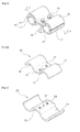
FIG. 3 is a perspective view of an apparatus for fixing hydraulic pipes for a construction machine according to a preferred embodiment of the present invention. -
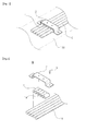
FIG. 4 is a schematically perspective view of an upper clamp of the apparatus for fixing hydraulic pipes according to the present invention. -
FIG. 5 is a schematically perspective view of a lower clamp of the apparatus for fixing hydraulic pipes according to the present invention. -
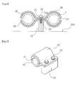
FIG. 6 is a sectional view taken along the line of A-A ofFIG. 3 . -
FIG. 7 is a perspective view of an apparatus for fixing hydraulic pipes for a construction machine according to another preferred embodiment of the present invention. - Reference will be now made in detail to the preferred embodiments of the present invention with reference to the attached drawings.
- Referring to
FIGS. 3 to 6 , a preferred embodiment of the present invention will be described. - An apparatus for fixing hydraulic pipes for a construction machine, which has a hydraulic pipe clamp for fixing a plurality of
pipes 10 to aboom structure 100, includes: alower clamp 20 having amounting hole 21; a clampposition setting member 22 for fixing thelower clamp 20 to one side of theboom structure 100 through aclamp support member 23 coupled to themounting hole 21; anupper clamp 30 coupled onto thelower clamp 20 and having aninterference prevention groove 31 in which ahead portion 23a of theclamp support member 23 is placed; and vibration-proof members clamps pipes 10. - The
clamp support member 23 may be a flat headed bolt in consideration of a pipe support load, and theinterference prevention groove 31 may be a through hole. - Moreover, the clamp
position setting member 22 includes a metal sheet material attached to an upper portion of theboom structure 100, and it is preferable that theupper clamp 30 and thelower clamp 20 are spaced apart from each other at a predetermined interval on theboom structure 100 by the clampposition setting member 22 when thepipes 10 are mounted. - The
lower clamp 20 includes aflat plate portion 25 adjacent to themounting hole 21 andpipe support portions 26 extending from theflat plate portion 25 to support thepipes 10. - It is preferable that the
pipe support portions 26 are formed at both sides of theflat plate portion 25 so that thepipes 10 are arranged at a predetermined interval. - Furthermore, the
upper clamp 30 includes aflat plate portion 35 adjacent to theinterference prevention groove 31 andpipe cover portions 36 extending from theflat plate portion 35 to cover thepipes 10. - The
lower clamp 20 and theupper clamp 30 respectively havecoupling holes 24 to which afixing member 33 for fixing thelower clamp 20 and theupper clamp 30 to the clampposition setting member 22 is coupled, and thecoupling holes 24 are formed on theflat plate portions - Preferably, the pipe support
portions 26 and thepipe cover portions 36 are respectively formed in a semicircular shape in order to protect and maintain thepipes 10 at predetermined intervals. - A vibration-
proof member 40 is mounted between theupper clamp 30 and thelower clamp 20, and preferably, vibration-proof members 40 are respectively mounted between thepipe support portions 26 and thepipe cover portions 36. - The vibration-
proof member 40 includes a plurality of divided vibration-proof pieces 41 and separation-preventingjaws 42 respectively formed at front ends of the vibration-proof pieces 41. - The vibration-
proof pieces 41 may be divided in a longitudinal direction of thepipe 10, and according to circumstances, may be dividedly formed on the outer circumferential surface of thepipe 10 in numbers. - The front end portion of the
pipe cover portion 35 of theupper clamp 30 and the front end portion of thepipe support portion 25 of thelower clamp 20 are kept in a noncontact condition to each other when they are assembled in consideration of pressure suitable for diameter or size of thepipe 10. If the diameter of thepipe 10 required according to the specifications of the construction machine is too large or a user wants to regulate pressure, an interval between the front end portion of thepipe cover portion 35 of theupper clamp 30 and the front end portion of thepipe support portion 25 of thelower clamp 20 can be regulated. - The above-mentioned pressure means a force that the
pipe cover portion 35 of theupper clamp 30 and thepipe support portion 25 of thelower clamp 20 compresses and supports thepipes 100 in a state where the pipes are completely assembled, and can be changed in such a fashion that various elastic forces can be added according to changes of qualities of materials. - In the meantime, according to
FIG. 7 illustrating another preferred embodiment of the present invention, in consideration of other interference of adjacent pipes, theclamps FIG. 6 may be transformed in an asymmetrical structure. - For instance, a
pipe cover portion 50 and a pipe support portion 51 may be formed only at one side of theflat plate portions pipe support portion 26 and thepipe cover portion 36 according to the demand of pipes. - Referring to the above preferred embodiments, the action and the operation principle of the apparatus for fixing hydraulic pipes for a construction machine according to the present invention will be described.
- When the
pipes 10, including hydraulic hoses and hydraulic pipes, are assembled and mounted on theboom structure 100 of the construction machine, the clampposition setting member 22 is previously attached to the upper portion of theboom structure 100. - The clamp
position setting member 22 serves to set the previously fixed position of thelower clamp 20. That is, after the clampposition setting member 22 is attached to theboom structure 100, theclamp support member 23 is mounted on themounting hole 21 of the clampposition setting member 22, and in this instance, the head portion of theclamp support member 23 is seated on theinterference prevention groove 31 formed in theflat plate portion 35 of theupper clamp 30. - The
interference prevention groove 31 has the through hole structure opposed to themounting hole 21, and in this instance, theupper clamp 30 and thelower clamp 20 are mounted in an approximately symmetrical structure. - After the assembly of the pipes is finished, the clamp support member does not project and is not exposed to the outside of the
upper clamp 30 and thelower clamp 20 is firmly fixed and maintained without any interference with other pipes. - Meanwhile, in order to restrict vibration applied to the
pipes 10, the vibration-proof member 40 may be previously seated inside thepipe support portion 26, but for convenience in work, the vibration-proof member 40 may be previously assembled to thepipe 10 in a forcedly fit state. - When the
pipes 10 are seated in thepipe support portions 26 and the vibration-proof members 40 of thelower clamp 20 in an approximately parallel state, theflat plate portion 35 of theupper clamp 30 comes in surface contact with theflat plate portion 25 of thelower clamp 20, and then, theupper clamp 30 and thelower clamp 20 are firmly fixed by thefixing member 33. - After the pipes are completely assembled, the front end portion of the
pipe cover portion 35 of theupper clamp 30 and the front end portion of thepipe support portion 25 of thelower clamp 20 supports thepipes 10 in the mutually noncontact state. - The structure illustrated in
FIG. 7 is advantageous when just one pipe is mounted to theboom structure 100. The operation principle that thepipe 10 is seated inside thepipe cover portion 50 of theupper clamp 50 and the pipe support portion 51 of thelower clamp 20 in a non-parallel state is the same as the above description, and hence, its detailed description will be omitted. - The apparatus for fixing hydraulic pipes for a construction machine according to the present invention can first assemble the
lower clamp 20 through the clampposition setting member 22 and theclamp support member 23, and then, simply assemble and install theupper clamp 30 for fixing the pipes, and hence, the user can effectively assemble the pipes without using any crane or jig that is additionally required in the prior art. - Additionally, the pipe assembly work according to the present invention can solve problems of the prior art in that the position setting and fixing of the lower clamp on the boom structure of a sheet are not good during the assembling process and in that it is difficult to assemble the clamps and accidents are caused due to a severe movement. Moreover, after the assembly of the pipes is finished, the clamp position setting member for fixing the clamps is completely embedded in the upper clamp so as to restrict the external interference.
Claims (8)
- An apparatus for fixing hydraulic pipes for a construction machine, which has a hydraulic pipe clamp for fixing a plurality of pipes to a boom structure, comprising:a lower clamp having a mounting hole;a clamp position setting member for fixing the lower clamp to one side of the boom structure through a clamp support member coupled to the mounting hole;an upper clamp coupled onto the lower clamp and having an interference prevention groove in which a head portion of the clamp position setting member is placed; andvibration-proof members attached to the interiors of the clamps to absorb vibration of the pipes.
- The apparatus for fixing hydraulic pipes according to claim 1, wherein the lower clamp comprises a flat plate portion adjacent to the mounting hole and a pipe support portion extending from the flat plate portion to support the pipe.
- The apparatus for fixing hydraulic pipes according to claim 1, wherein the upper clamp comprises a flat plate portion adjacent to the interference prevention groove and a pipe cover portion extending from the flat plate portion to cover the pipe.
- The apparatus for fixing hydraulic pipes according to claim 2, wherein the pipe support portion is in the form of a semicircular shape.
- The apparatus for fixing hydraulic pipes according to claim 3, wherein the pipe cover portion is in the form of a semicircular shape.
- The apparatus for fixing hydraulic pipes according to claim 1, wherein the vibration-proof member is installed between the upper clamp and the lower clamp.
- The apparatus for fixing hydraulic pipes according to claim 6, wherein the vibration-proof member includes a plurality of divided vibration-proof pieces and is installed between the pipe support portion and the pipe cover portion the vibration-proof member is installed between the pipe support portion and the pipe cover portion, and is composed of a plurality of vibration-proof pieces.
- The apparatus for fixing hydraulic pipes according to claim 3, wherein the interference prevention groove is penetratingly formed in the flat plate portion.
Applications Claiming Priority (1)
| Application Number | Priority Date | Filing Date | Title |
|---|---|---|---|
| PCT/KR2010/003098 WO2011145756A1 (en) | 2010-05-17 | 2010-05-17 | Fixing device of hydraulic pipe of construction machine |
Publications (3)
| Publication Number | Publication Date |
|---|---|
| EP2573277A1 true EP2573277A1 (en) | 2013-03-27 |
| EP2573277A4 EP2573277A4 (en) | 2014-04-23 |
| EP2573277B1 EP2573277B1 (en) | 2017-02-15 |
Family
ID=44991838
Family Applications (1)
| Application Number | Title | Priority Date | Filing Date |
|---|---|---|---|
| EP10851803.6A Not-in-force EP2573277B1 (en) | 2010-05-17 | 2010-05-17 | Fixing device of hydraulic pipe of construction machine |
Country Status (6)
| Country | Link |
|---|---|
| US (1) | US8770537B2 (en) |
| EP (1) | EP2573277B1 (en) |
| JP (1) | JP5602944B2 (en) |
| KR (1) | KR101737900B1 (en) |
| CN (1) | CN102859078A (en) |
| WO (1) | WO2011145756A1 (en) |
Cited By (4)
| Publication number | Priority date | Publication date | Assignee | Title |
|---|---|---|---|---|
| EP2955393A1 (en) * | 2014-06-13 | 2015-12-16 | Siemens Aktiengesellschaft | Connection clamp with metal wire mat as damping element |
| EP2960378A1 (en) * | 2014-06-23 | 2015-12-30 | Kobelco Construction Machinery Co., Ltd. | Pipe supporting device for construction machine |
| FR3077097A1 (en) * | 2018-01-22 | 2019-07-26 | Safran Aircraft Engines | COOLING DEVICE FOR TURBINE OF A TURBOMACHINE |
| FR3114346A1 (en) * | 2020-09-24 | 2022-03-25 | Safran Aircraft Engines | Turbojet turbine casing equipped with cooling tube mounting bracket |
Families Citing this family (50)
| Publication number | Priority date | Publication date | Assignee | Title |
|---|---|---|---|---|
| JP5403013B2 (en) * | 2011-08-24 | 2014-01-29 | コベルコ建機株式会社 | Piping mounting structure for work machines |
| CN103890278A (en) | 2011-10-17 | 2014-06-25 | 沃尔沃建造设备有限公司 | Device for fixing the hydraulic piping of construction equipment |
| WO2013081212A1 (en) * | 2011-11-30 | 2013-06-06 | 볼보 컨스트럭션 이큅먼트 에이비 | Hydraulic line fixing apparatus for boom swing-type excavators |
| EP2792881A4 (en) * | 2011-12-15 | 2016-07-06 | Volvo Constr Equip Ab | Input/output pipe reinforcing device for vehicle compressor |
| CN102588677A (en) * | 2012-02-29 | 2012-07-18 | 长城汽车股份有限公司 | Pipe fixing device with multiple holes |
| NO334470B1 (en) * | 2012-08-30 | 2014-03-17 | Nexans | Piggyback clamp |
| TWI507627B (en) * | 2012-12-03 | 2015-11-11 | Univ Nat Cheng Kung | Pipeline transfer assembly and pipe transfer kit |
| US9643800B2 (en) * | 2013-02-23 | 2017-05-09 | Phillip Douglas | Horizontal support system |
| CA2913144A1 (en) * | 2013-05-30 | 2014-12-04 | Volvo Construction Equipment Ab | Pipe fixing device for construction machine |
| CN103322307A (en) * | 2013-06-24 | 2013-09-25 | 向荣集团有限公司 | Adjustable cable fixer |
| US9142946B2 (en) * | 2013-06-27 | 2015-09-22 | Caterpillar Inc. | Cable retention system |
| US20150013817A1 (en) * | 2013-07-12 | 2015-01-15 | Larry McMurray | Actuated Moment Arm |
| US9532503B2 (en) * | 2013-10-31 | 2017-01-03 | Ernest Kalani Makainai | Monofilament line holder for grass trimmers |
| US20150217154A1 (en) | 2014-02-06 | 2015-08-06 | Performance Advantage Company, Inc. | Universal nozzle connector with an adjustable mount |
| FR3021700B1 (en) * | 2014-05-27 | 2016-07-01 | Snecma | DEVICE FOR MAINTAINING A COOLING TUBE FOR A TURBOJET CARTRIDGE |
| US9648993B2 (en) * | 2014-10-23 | 2017-05-16 | Nathaniel Gainey | Towel and washcloth holding device |
| US10376324B2 (en) | 2014-10-30 | 2019-08-13 | Intuitive Surgical Operations, Inc. | System and method for articulated arm stabilization |
| CN107110005B (en) | 2014-11-03 | 2019-06-28 | 康明斯有限公司 | Methods of Using Wear Kits to Support Charge Air Pipes and Manage Thermal Expansion |
| CN107076082B (en) * | 2014-11-19 | 2022-12-20 | 大陆汽车有限公司 | Fuel rail assembly for internal combustion engine |
| FR3040429B1 (en) * | 2015-08-27 | 2019-06-07 | Safran Aircraft Engines | DEVICE FOR FASTENING AIR COOLED COOLING RAMPS OF A TURBOMACHINE TURBINE |
| KR20170000956U (en) * | 2015-09-04 | 2017-03-14 | 현대중공업 주식회사 | Rubber Clamp for Hydraulic Pipe in Construction Equipment |
| JP6241466B2 (en) * | 2015-09-11 | 2017-12-06 | コベルコ建機株式会社 | Work machine |
| JP6629653B2 (en) * | 2016-03-23 | 2020-01-15 | 住友ナコ フォ−クリフト株式会社 | Piping fixture |
| CN107774815A (en) * | 2016-08-30 | 2018-03-09 | 江苏凤凰木业有限公司 | Detachable step pipe fastening frame |
| US20200149662A1 (en) * | 2017-03-17 | 2020-05-14 | Meggitt Safety Systems, Inc. | High temperature clamps and methods of making the same |
| US10320173B2 (en) * | 2017-03-28 | 2019-06-11 | Atkore Steel Components, Inc. | Conduit support assembly |
| NL2019747B1 (en) * | 2017-10-17 | 2019-04-24 | Walraven Holding Bv J Van | Riser clamp with a vibration isolation element |
| KR102042973B1 (en) * | 2017-11-16 | 2019-11-11 | 두산중공업 주식회사 | Burner Having Transition Piece Supporting Member, And Gas Turbine Having The Same |
| US10415746B2 (en) * | 2018-01-31 | 2019-09-17 | G.C. Hoyle Company Llc | Vertical support bracket for self-leveling devices |
| CN108716570A (en) * | 2018-07-26 | 2018-10-30 | 徐州徐工铁路装备有限公司 | A kind of thruster of jumbo hose support |
| CN112470357A (en) * | 2018-07-27 | 2021-03-09 | 康普技术有限责任公司 | cable hanger assembly |
| US10663353B2 (en) * | 2018-08-23 | 2020-05-26 | Kidde Technologies, Inc. | Clamp for sensors |
| CN110894899B (en) * | 2018-09-13 | 2021-11-19 | 陕西重型汽车有限公司 | Double-barrelled fixed clamp |
| CN108978745B (en) * | 2018-09-28 | 2021-05-28 | 景冲 | An excavator with stable oil path |
| US11384867B2 (en) | 2019-03-27 | 2022-07-12 | Great Plains Manufacturing, Inc. | Hydraulic hose clamp |
| US10907750B2 (en) * | 2019-04-29 | 2021-02-02 | Aptiv Technologies Limited | Modular retainer assembly |
| GB2584882A (en) * | 2019-06-19 | 2020-12-23 | Airbus Operations Ltd | Pipe support |
| US11092079B2 (en) * | 2019-07-18 | 2021-08-17 | Kidde Technologies, Inc. | Support arrangements, fire and overheat detection systems, and methods of making support arrangements for fire and overheat detection systems |
| CN111703715A (en) * | 2020-06-24 | 2020-09-25 | 祖树印 | Fixing clamp for football field stand column pipeline transportation |
| KR102237537B1 (en) * | 2020-09-15 | 2021-04-07 | 대모 엔지니어링 주식회사 | Quick Change Device |
| JP2022134381A (en) * | 2021-03-03 | 2022-09-15 | 株式会社椿本チエイン | Flat-shape transmission apparatus and clamp device |
| US12129946B2 (en) * | 2021-07-12 | 2024-10-29 | Dustin Zander | Protective bracket for loader hose lines |
| FR3126445B1 (en) * | 2021-09-02 | 2025-05-02 | Safran Aircraft Engines | Cooling device for a turbine of a turbomachine |
| US11859743B2 (en) * | 2021-10-15 | 2024-01-02 | General Electric Company | System for spacing and fastening tubular structures |
| US11898682B2 (en) * | 2021-10-15 | 2024-02-13 | General Electric Company | System for spacing and fastening tubular structures |
| KR102387668B1 (en) * | 2021-12-29 | 2022-04-19 | 명보 주식회사 | Rubber dam with improved standing and fall function |
| CN114857361A (en) * | 2022-04-27 | 2022-08-05 | 重庆英仕达新型建材有限公司 | An easy-to-install anti-vibration bracket |
| US11959571B2 (en) | 2022-08-18 | 2024-04-16 | Panduit Corp. | Cable clamp with adjustment latches |
| US20250055270A1 (en) * | 2023-08-08 | 2025-02-13 | Maxdao Inc. | Hyrid cable hanger system |
| US20250251059A1 (en) * | 2024-02-07 | 2025-08-07 | Tom Nepola | High vibration clamp assembly |
Family Cites Families (33)
| Publication number | Priority date | Publication date | Assignee | Title |
|---|---|---|---|---|
| GB1458201A (en) * | 1973-10-31 | 1976-12-08 | United Carr Ltd | Resilient retainer |
| JPS59168086U (en) * | 1983-04-26 | 1984-11-10 | 株式会社小松製作所 | Piping clamp device |
| FR2601087A1 (en) * | 1986-07-01 | 1988-01-08 | Legendre Serge | Support forming a collar with controlled opening, for aligning pipelines |
| JP2511693Y2 (en) * | 1990-11-19 | 1996-09-25 | 株式会社東郷製作所 | Anti-vibration clamp |
| DE4207666C2 (en) * | 1992-03-11 | 1994-05-11 | Deutsche Aerospace Airbus | Device for fixing components |
| US5435506A (en) * | 1994-03-02 | 1995-07-25 | United Technologies Corporation | Clamp with mechanically attached grommet |
| JP2938373B2 (en) * | 1995-09-06 | 1999-08-23 | 住友建機株式会社 | Hydraulic piping in excavator |
| KR19980011572U (en) | 1996-08-20 | 1998-05-25 | 추호석 | Heavy Duty Hydraulic Hose Fixture |
| US5941483A (en) * | 1998-04-24 | 1999-08-24 | Volvo Trucks North America, Inc. | Service line clamp with cable tie mount |
| US6234277B1 (en) * | 1999-05-07 | 2001-05-22 | Draka Elevator Products, Inc. | Cable sway reduction device |
| JP2002327453A (en) * | 2001-05-07 | 2002-11-15 | Komatsu Ltd | Hydraulic piping clamp device for construction machine working machine |
| US6669150B2 (en) * | 2001-05-31 | 2003-12-30 | Illinois Tool Works Inc. | Clip assembly with positive locating features |
| JP2003003516A (en) * | 2001-06-20 | 2003-01-08 | Hitachi Constr Mach Co Ltd | Clamping structure for preventing hydraulic hose from falling down sideways |
| US7401753B2 (en) * | 2001-07-10 | 2008-07-22 | Harley-Davidson Motor Company Group, Inc. | Exhaust clamp for a motorcycle |
| CN2506833Y (en) * | 2001-08-25 | 2002-08-21 | 宁波阿勒法管系机械制造有限公司 | Foldable pipe hanging frame |
| JP4592238B2 (en) * | 2001-09-28 | 2010-12-01 | 三菱農機株式会社 | Hydraulic piping fixing device |
| AU2003254687A1 (en) * | 2002-09-25 | 2004-04-19 | Pma Ag | Pipe clip |
| JP2004138095A (en) * | 2002-10-15 | 2004-05-13 | Koganei Corp | Conductive tube holder |
| US6883761B2 (en) * | 2003-02-13 | 2005-04-26 | General Electric Company | Support for tubular members |
| US8523120B2 (en) * | 2004-06-14 | 2013-09-03 | Komatsu Ltd. | Component support device and construction machine with component attached via the same |
| JP4631338B2 (en) * | 2004-07-23 | 2011-02-16 | トヨタ自動車株式会社 | Clamp |
| CN2722006Y (en) * | 2004-07-30 | 2005-08-31 | 波伦北克有限公司 | Double tube clamp |
| JP4268114B2 (en) | 2004-10-26 | 2009-05-27 | キャタピラージャパン株式会社 | Hydraulic piping connection structure for construction machinery |
| JP2007314980A (en) * | 2006-05-24 | 2007-12-06 | Shin Caterpillar Mitsubishi Ltd | Hydraulic piping structure of working machine |
| JP4738272B2 (en) * | 2006-07-20 | 2011-08-03 | 住友建機株式会社 | Clamping device for hydraulic piping of construction machinery |
| CN1912438A (en) * | 2006-08-24 | 2007-02-14 | 徐州恒天德尔重工科技有限公司 | Clip of petroleum pipeline |
| KR200455326Y1 (en) * | 2006-10-31 | 2011-08-30 | 현대중공업 주식회사 | Pipe clamps on construction equipment |
| US20080245932A1 (en) * | 2006-12-28 | 2008-10-09 | Prellwitz Martin W | Composite tube clamp and method for making same |
| CN201149131Y (en) * | 2007-12-26 | 2008-11-12 | 三一重型装备有限公司 | Rotating pipe clip |
| JP2009209575A (en) * | 2008-03-04 | 2009-09-17 | Hitachi Constr Mach Co Ltd | Construction equipment |
| CN201239678Y (en) * | 2008-08-07 | 2009-05-20 | 潘灵钢 | Double-tube positioning clip for gas pipe and conveying pipe of electric spray gun bucket |
| CN101525947A (en) * | 2009-03-05 | 2009-09-09 | 杜明清 | Three-pole steel tube lapping fastener |
| JP5611881B2 (en) * | 2010-08-27 | 2014-10-22 | 日立建機株式会社 | Construction equipment working equipment |
-
2010
- 2010-05-17 JP JP2013511089A patent/JP5602944B2/en not_active Expired - Fee Related
- 2010-05-17 EP EP10851803.6A patent/EP2573277B1/en not_active Not-in-force
- 2010-05-17 WO PCT/KR2010/003098 patent/WO2011145756A1/en not_active Ceased
- 2010-05-17 CN CN2010800663828A patent/CN102859078A/en active Pending
- 2010-05-17 KR KR1020127025423A patent/KR101737900B1/en not_active Expired - Fee Related
- 2010-05-17 US US13/639,936 patent/US8770537B2/en active Active
Cited By (8)
| Publication number | Priority date | Publication date | Assignee | Title |
|---|---|---|---|---|
| EP2955393A1 (en) * | 2014-06-13 | 2015-12-16 | Siemens Aktiengesellschaft | Connection clamp with metal wire mat as damping element |
| WO2015189105A1 (en) * | 2014-06-13 | 2015-12-17 | Siemens Aktiengesellschaft | Connecting clip having a metal wire mat as a damping element |
| US10132429B2 (en) | 2014-06-13 | 2018-11-20 | Siemens Aktiengesellschaft | Connecting clip having a metal wire mat as a damping element |
| EP2960378A1 (en) * | 2014-06-23 | 2015-12-30 | Kobelco Construction Machinery Co., Ltd. | Pipe supporting device for construction machine |
| US9482253B2 (en) | 2014-06-23 | 2016-11-01 | Kobelco Construction Machinery Co., Ltd. | Pipe supporting device for construction machine |
| FR3077097A1 (en) * | 2018-01-22 | 2019-07-26 | Safran Aircraft Engines | COOLING DEVICE FOR TURBINE OF A TURBOMACHINE |
| US11371387B2 (en) | 2018-01-22 | 2022-06-28 | Safran Aircraft Engines | Cooling device for a turbine of a turbomachine |
| FR3114346A1 (en) * | 2020-09-24 | 2022-03-25 | Safran Aircraft Engines | Turbojet turbine casing equipped with cooling tube mounting bracket |
Also Published As
| Publication number | Publication date |
|---|---|
| KR101737900B1 (en) | 2017-05-19 |
| EP2573277A4 (en) | 2014-04-23 |
| KR20130085938A (en) | 2013-07-30 |
| US8770537B2 (en) | 2014-07-08 |
| CN102859078A (en) | 2013-01-02 |
| US20130048826A1 (en) | 2013-02-28 |
| JP2013529270A (en) | 2013-07-18 |
| WO2011145756A1 (en) | 2011-11-24 |
| JP5602944B2 (en) | 2014-10-08 |
| EP2573277B1 (en) | 2017-02-15 |
Similar Documents
| Publication | Publication Date | Title |
|---|---|---|
| EP2573277B1 (en) | Fixing device of hydraulic pipe of construction machine | |
| US20150246450A1 (en) | Robot with fixing device for restricting relative rotating motion of two members and such fixing device | |
| KR101677891B1 (en) | Connecting tool for salvage | |
| JP5755203B2 (en) | Wire rope gripper | |
| JP2015090199A (en) | Buckling prevention device for suspension type support device | |
| JP5946752B2 (en) | Wire rope gripper | |
| CN211398817U (en) | Protective device for engineering pipeline construction | |
| KR20130003976U (en) | Utility line for mounting suporting jig | |
| JP5639099B2 (en) | Piping clamp and piping fixing structure for work equipment | |
| JP2014143871A (en) | Fixture for overhead wire lean-over instrument and method of fixing overhead wire lean-over instrument by using the same | |
| CN205896408U (en) | Hose fixing device | |
| CN109996752B (en) | Fall Protection Equipment for Hoists | |
| JP4757272B2 (en) | Hydraulic hose clamp device for construction machinery | |
| JP7014034B2 (en) | Long body bending inhibitor | |
| KR20130005829U (en) | Seat assembly for fire extinguisher of ship | |
| JP3179886U (en) | Tombstone suspension | |
| KR20090001271U (en) | Workline holder | |
| JPH0510547U (en) | Pipe clamp device | |
| JP2015193977A (en) | Steel pipe pile driving aid | |
| CN222860942U (en) | Lifting tool | |
| CN203395064U (en) | Vibration reduction isolation assembly and corresponding vehicle | |
| JP6304799B2 (en) | Manholes and manhole hanging methods | |
| KR20140006092U (en) | Trolley locking device | |
| KR20100001441U (en) | Working pulley | |
| KR200339749Y1 (en) | A clampping pad for pipe |
Legal Events
| Date | Code | Title | Description |
|---|---|---|---|
| PUAI | Public reference made under article 153(3) epc to a published international application that has entered the european phase |
Free format text: ORIGINAL CODE: 0009012 |
|
| 17P | Request for examination filed |
Effective date: 20121031 |
|
| AK | Designated contracting states |
Kind code of ref document: A1 Designated state(s): AL AT BE BG CH CY CZ DE DK EE ES FI FR GB GR HR HU IE IS IT LI LT LU LV MC MK MT NL NO PL PT RO SE SI SK SM TR |
|
| DAX | Request for extension of the european patent (deleted) | ||
| A4 | Supplementary search report drawn up and despatched |
Effective date: 20140324 |
|
| RIC1 | Information provided on ipc code assigned before grant |
Ipc: F16L 3/23 20060101ALI20140318BHEP Ipc: F16L 3/22 20060101ALI20140318BHEP Ipc: E02F 3/36 20060101AFI20140318BHEP Ipc: F16L 3/04 20060101ALI20140318BHEP Ipc: E02F 9/00 20060101ALI20140318BHEP |
|
| REG | Reference to a national code |
Ref country code: DE Ref legal event code: R079 Ref document number: 602010040149 Country of ref document: DE Free format text: PREVIOUS MAIN CLASS: E02F0003360000 Ipc: F16L0003100000 |
|
| GRAP | Despatch of communication of intention to grant a patent |
Free format text: ORIGINAL CODE: EPIDOSNIGR1 |
|
| RIC1 | Information provided on ipc code assigned before grant |
Ipc: F16L 55/035 20060101ALI20160603BHEP Ipc: E02F 9/22 20060101ALI20160603BHEP Ipc: F16L 3/10 20060101AFI20160603BHEP Ipc: F16L 3/237 20060101ALI20160603BHEP |
|
| INTG | Intention to grant announced |
Effective date: 20160701 |
|
| GRAJ | Information related to disapproval of communication of intention to grant by the applicant or resumption of examination proceedings by the epo deleted |
Free format text: ORIGINAL CODE: EPIDOSDIGR1 |
|
| GRAS | Grant fee paid |
Free format text: ORIGINAL CODE: EPIDOSNIGR3 |
|
| GRAP | Despatch of communication of intention to grant a patent |
Free format text: ORIGINAL CODE: EPIDOSNIGR1 |
|
| INTC | Intention to grant announced (deleted) | ||
| INTG | Intention to grant announced |
Effective date: 20161209 |
|
| GRAA | (expected) grant |
Free format text: ORIGINAL CODE: 0009210 |
|
| AK | Designated contracting states |
Kind code of ref document: B1 Designated state(s): AL AT BE BG CH CY CZ DE DK EE ES FI FR GB GR HR HU IE IS IT LI LT LU LV MC MK MT NL NO PL PT RO SE SI SK SM TR |
|
| REG | Reference to a national code |
Ref country code: CH Ref legal event code: EP Ref country code: GB Ref legal event code: FG4D |
|
| REG | Reference to a national code |
Ref country code: IE Ref legal event code: FG4D |
|
| REG | Reference to a national code |
Ref country code: AT Ref legal event code: REF Ref document number: 868117 Country of ref document: AT Kind code of ref document: T Effective date: 20170315 |
|
| REG | Reference to a national code |
Ref country code: DE Ref legal event code: R096 Ref document number: 602010040149 Country of ref document: DE |
|
| REG | Reference to a national code |
Ref country code: NL Ref legal event code: MP Effective date: 20170215 |
|
| REG | Reference to a national code |
Ref country code: LT Ref legal event code: MG4D |
|
| REG | Reference to a national code |
Ref country code: AT Ref legal event code: MK05 Ref document number: 868117 Country of ref document: AT Kind code of ref document: T Effective date: 20170215 |
|
| PG25 | Lapsed in a contracting state [announced via postgrant information from national office to epo] |
Ref country code: NO Free format text: LAPSE BECAUSE OF FAILURE TO SUBMIT A TRANSLATION OF THE DESCRIPTION OR TO PAY THE FEE WITHIN THE PRESCRIBED TIME-LIMIT Effective date: 20170515 Ref country code: HR Free format text: LAPSE BECAUSE OF FAILURE TO SUBMIT A TRANSLATION OF THE DESCRIPTION OR TO PAY THE FEE WITHIN THE PRESCRIBED TIME-LIMIT Effective date: 20170215 Ref country code: GR Free format text: LAPSE BECAUSE OF FAILURE TO SUBMIT A TRANSLATION OF THE DESCRIPTION OR TO PAY THE FEE WITHIN THE PRESCRIBED TIME-LIMIT Effective date: 20170516 Ref country code: LT Free format text: LAPSE BECAUSE OF FAILURE TO SUBMIT A TRANSLATION OF THE DESCRIPTION OR TO PAY THE FEE WITHIN THE PRESCRIBED TIME-LIMIT Effective date: 20170215 Ref country code: FI Free format text: LAPSE BECAUSE OF FAILURE TO SUBMIT A TRANSLATION OF THE DESCRIPTION OR TO PAY THE FEE WITHIN THE PRESCRIBED TIME-LIMIT Effective date: 20170215 |
|
| PG25 | Lapsed in a contracting state [announced via postgrant information from national office to epo] |
Ref country code: ES Free format text: LAPSE BECAUSE OF FAILURE TO SUBMIT A TRANSLATION OF THE DESCRIPTION OR TO PAY THE FEE WITHIN THE PRESCRIBED TIME-LIMIT Effective date: 20170215 Ref country code: NL Free format text: LAPSE BECAUSE OF FAILURE TO SUBMIT A TRANSLATION OF THE DESCRIPTION OR TO PAY THE FEE WITHIN THE PRESCRIBED TIME-LIMIT Effective date: 20170215 Ref country code: SE Free format text: LAPSE BECAUSE OF FAILURE TO SUBMIT A TRANSLATION OF THE DESCRIPTION OR TO PAY THE FEE WITHIN THE PRESCRIBED TIME-LIMIT Effective date: 20170215 Ref country code: LV Free format text: LAPSE BECAUSE OF FAILURE TO SUBMIT A TRANSLATION OF THE DESCRIPTION OR TO PAY THE FEE WITHIN THE PRESCRIBED TIME-LIMIT Effective date: 20170215 Ref country code: AT Free format text: LAPSE BECAUSE OF FAILURE TO SUBMIT A TRANSLATION OF THE DESCRIPTION OR TO PAY THE FEE WITHIN THE PRESCRIBED TIME-LIMIT Effective date: 20170215 Ref country code: LU Free format text: LAPSE BECAUSE OF NON-PAYMENT OF DUE FEES Effective date: 20170531 Ref country code: BG Free format text: LAPSE BECAUSE OF FAILURE TO SUBMIT A TRANSLATION OF THE DESCRIPTION OR TO PAY THE FEE WITHIN THE PRESCRIBED TIME-LIMIT Effective date: 20170515 Ref country code: PT Free format text: LAPSE BECAUSE OF FAILURE TO SUBMIT A TRANSLATION OF THE DESCRIPTION OR TO PAY THE FEE WITHIN THE PRESCRIBED TIME-LIMIT Effective date: 20170615 |
|
| REG | Reference to a national code |
Ref country code: FR Ref legal event code: PLFP Year of fee payment: 8 |
|
| PG25 | Lapsed in a contracting state [announced via postgrant information from national office to epo] |
Ref country code: CZ Free format text: LAPSE BECAUSE OF FAILURE TO SUBMIT A TRANSLATION OF THE DESCRIPTION OR TO PAY THE FEE WITHIN THE PRESCRIBED TIME-LIMIT Effective date: 20170215 Ref country code: IT Free format text: LAPSE BECAUSE OF FAILURE TO SUBMIT A TRANSLATION OF THE DESCRIPTION OR TO PAY THE FEE WITHIN THE PRESCRIBED TIME-LIMIT Effective date: 20170215 Ref country code: RO Free format text: LAPSE BECAUSE OF FAILURE TO SUBMIT A TRANSLATION OF THE DESCRIPTION OR TO PAY THE FEE WITHIN THE PRESCRIBED TIME-LIMIT Effective date: 20170215 Ref country code: SK Free format text: LAPSE BECAUSE OF FAILURE TO SUBMIT A TRANSLATION OF THE DESCRIPTION OR TO PAY THE FEE WITHIN THE PRESCRIBED TIME-LIMIT Effective date: 20170215 Ref country code: EE Free format text: LAPSE BECAUSE OF FAILURE TO SUBMIT A TRANSLATION OF THE DESCRIPTION OR TO PAY THE FEE WITHIN THE PRESCRIBED TIME-LIMIT Effective date: 20170215 |
|
| REG | Reference to a national code |
Ref country code: DE Ref legal event code: R097 Ref document number: 602010040149 Country of ref document: DE |
|
| PG25 | Lapsed in a contracting state [announced via postgrant information from national office to epo] |
Ref country code: SM Free format text: LAPSE BECAUSE OF FAILURE TO SUBMIT A TRANSLATION OF THE DESCRIPTION OR TO PAY THE FEE WITHIN THE PRESCRIBED TIME-LIMIT Effective date: 20170215 Ref country code: DK Free format text: LAPSE BECAUSE OF FAILURE TO SUBMIT A TRANSLATION OF THE DESCRIPTION OR TO PAY THE FEE WITHIN THE PRESCRIBED TIME-LIMIT Effective date: 20170215 Ref country code: PL Free format text: LAPSE BECAUSE OF FAILURE TO SUBMIT A TRANSLATION OF THE DESCRIPTION OR TO PAY THE FEE WITHIN THE PRESCRIBED TIME-LIMIT Effective date: 20170215 |
|
| PLBE | No opposition filed within time limit |
Free format text: ORIGINAL CODE: 0009261 |
|
| STAA | Information on the status of an ep patent application or granted ep patent |
Free format text: STATUS: NO OPPOSITION FILED WITHIN TIME LIMIT |
|
| REG | Reference to a national code |
Ref country code: CH Ref legal event code: PL |
|
| 26N | No opposition filed |
Effective date: 20171116 |
|
| GBPC | Gb: european patent ceased through non-payment of renewal fee |
Effective date: 20170517 |
|
| PG25 | Lapsed in a contracting state [announced via postgrant information from national office to epo] |
Ref country code: MC Free format text: LAPSE BECAUSE OF FAILURE TO SUBMIT A TRANSLATION OF THE DESCRIPTION OR TO PAY THE FEE WITHIN THE PRESCRIBED TIME-LIMIT Effective date: 20170215 |
|
| REG | Reference to a national code |
Ref country code: IE Ref legal event code: MM4A |
|
| PG25 | Lapsed in a contracting state [announced via postgrant information from national office to epo] |
Ref country code: CH Free format text: LAPSE BECAUSE OF NON-PAYMENT OF DUE FEES Effective date: 20170531 Ref country code: SI Free format text: LAPSE BECAUSE OF FAILURE TO SUBMIT A TRANSLATION OF THE DESCRIPTION OR TO PAY THE FEE WITHIN THE PRESCRIBED TIME-LIMIT Effective date: 20170215 Ref country code: LI Free format text: LAPSE BECAUSE OF NON-PAYMENT OF DUE FEES Effective date: 20170531 |
|
| PG25 | Lapsed in a contracting state [announced via postgrant information from national office to epo] |
Ref country code: LU Free format text: LAPSE BECAUSE OF NON-PAYMENT OF DUE FEES Effective date: 20170517 |
|
| REG | Reference to a national code |
Ref country code: BE Ref legal event code: MM Effective date: 20170531 |
|
| PG25 | Lapsed in a contracting state [announced via postgrant information from national office to epo] |
Ref country code: IE Free format text: LAPSE BECAUSE OF NON-PAYMENT OF DUE FEES Effective date: 20170517 Ref country code: GB Free format text: LAPSE BECAUSE OF NON-PAYMENT OF DUE FEES Effective date: 20170517 |
|
| REG | Reference to a national code |
Ref country code: FR Ref legal event code: PLFP Year of fee payment: 9 |
|
| PG25 | Lapsed in a contracting state [announced via postgrant information from national office to epo] |
Ref country code: BE Free format text: LAPSE BECAUSE OF NON-PAYMENT OF DUE FEES Effective date: 20170531 |
|
| PG25 | Lapsed in a contracting state [announced via postgrant information from national office to epo] |
Ref country code: MT Free format text: LAPSE BECAUSE OF NON-PAYMENT OF DUE FEES Effective date: 20170517 |
|
| PG25 | Lapsed in a contracting state [announced via postgrant information from national office to epo] |
Ref country code: HU Free format text: LAPSE BECAUSE OF FAILURE TO SUBMIT A TRANSLATION OF THE DESCRIPTION OR TO PAY THE FEE WITHIN THE PRESCRIBED TIME-LIMIT; INVALID AB INITIO Effective date: 20100517 |
|
| PG25 | Lapsed in a contracting state [announced via postgrant information from national office to epo] |
Ref country code: CY Free format text: LAPSE BECAUSE OF NON-PAYMENT OF DUE FEES Effective date: 20170215 |
|
| PG25 | Lapsed in a contracting state [announced via postgrant information from national office to epo] |
Ref country code: MK Free format text: LAPSE BECAUSE OF FAILURE TO SUBMIT A TRANSLATION OF THE DESCRIPTION OR TO PAY THE FEE WITHIN THE PRESCRIBED TIME-LIMIT Effective date: 20170215 |
|
| PG25 | Lapsed in a contracting state [announced via postgrant information from national office to epo] |
Ref country code: TR Free format text: LAPSE BECAUSE OF FAILURE TO SUBMIT A TRANSLATION OF THE DESCRIPTION OR TO PAY THE FEE WITHIN THE PRESCRIBED TIME-LIMIT Effective date: 20170215 |
|
| PG25 | Lapsed in a contracting state [announced via postgrant information from national office to epo] |
Ref country code: AL Free format text: LAPSE BECAUSE OF FAILURE TO SUBMIT A TRANSLATION OF THE DESCRIPTION OR TO PAY THE FEE WITHIN THE PRESCRIBED TIME-LIMIT Effective date: 20170215 Ref country code: IS Free format text: LAPSE BECAUSE OF FAILURE TO SUBMIT A TRANSLATION OF THE DESCRIPTION OR TO PAY THE FEE WITHIN THE PRESCRIBED TIME-LIMIT Effective date: 20170615 |
|
| PGFP | Annual fee paid to national office [announced via postgrant information from national office to epo] |
Ref country code: FR Payment date: 20230523 Year of fee payment: 14 Ref country code: DE Payment date: 20230530 Year of fee payment: 14 |
|
| REG | Reference to a national code |
Ref country code: DE Ref legal event code: R119 Ref document number: 602010040149 Country of ref document: DE |
|
| PG25 | Lapsed in a contracting state [announced via postgrant information from national office to epo] |
Ref country code: DE Free format text: LAPSE BECAUSE OF NON-PAYMENT OF DUE FEES Effective date: 20241203 |
|
| PG25 | Lapsed in a contracting state [announced via postgrant information from national office to epo] |
Ref country code: FR Free format text: LAPSE BECAUSE OF NON-PAYMENT OF DUE FEES Effective date: 20240531 |