EP2573266B1 - Procédé de commande d'un procédé de chargement d'un véhicule de transport avec des produits de fraisage, dispositif destiné à réaliser un tel procédé et dispositif de fraisage - Google Patents
Procédé de commande d'un procédé de chargement d'un véhicule de transport avec des produits de fraisage, dispositif destiné à réaliser un tel procédé et dispositif de fraisage Download PDFInfo
- Publication number
- EP2573266B1 EP2573266B1 EP12006594.1A EP12006594A EP2573266B1 EP 2573266 B1 EP2573266 B1 EP 2573266B1 EP 12006594 A EP12006594 A EP 12006594A EP 2573266 B1 EP2573266 B1 EP 2573266B1
- Authority
- EP
- European Patent Office
- Prior art keywords
- transport container
- milling
- transport
- conveyor
- loading process
- Prior art date
- Legal status (The legal status is an assumption and is not a legal conclusion. Google has not performed a legal analysis and makes no representation as to the accuracy of the status listed.)
- Active
Links
- 238000003801 milling Methods 0.000 title claims description 243
- 238000000034 method Methods 0.000 title claims description 99
- 239000000463 material Substances 0.000 title claims description 73
- 230000008569 process Effects 0.000 claims description 67
- 230000001276 controlling effect Effects 0.000 claims description 24
- 230000011664 signaling Effects 0.000 claims description 15
- 230000006870 function Effects 0.000 claims description 14
- 238000001514 detection method Methods 0.000 claims description 12
- 238000012544 monitoring process Methods 0.000 claims description 12
- 230000003287 optical effect Effects 0.000 claims description 7
- 239000002689 soil Substances 0.000 claims description 7
- 230000033001 locomotion Effects 0.000 claims description 6
- 230000001105 regulatory effect Effects 0.000 claims description 5
- 230000004913 activation Effects 0.000 claims description 4
- 238000005096 rolling process Methods 0.000 claims description 3
- 230000009849 deactivation Effects 0.000 claims 1
- 230000002093 peripheral effect Effects 0.000 description 7
- 238000013459 approach Methods 0.000 description 5
- 230000033228 biological regulation Effects 0.000 description 5
- 230000008859 change Effects 0.000 description 3
- 238000010276 construction Methods 0.000 description 3
- 238000013461 design Methods 0.000 description 3
- 230000001960 triggered effect Effects 0.000 description 3
- 230000008901 benefit Effects 0.000 description 2
- 238000005429 filling process Methods 0.000 description 2
- 230000005484 gravity Effects 0.000 description 2
- 230000003993 interaction Effects 0.000 description 2
- 238000005065 mining Methods 0.000 description 2
- 230000003252 repetitive effect Effects 0.000 description 2
- 230000003213 activating effect Effects 0.000 description 1
- 230000006399 behavior Effects 0.000 description 1
- 230000005540 biological transmission Effects 0.000 description 1
- 230000015556 catabolic process Effects 0.000 description 1
- 238000004891 communication Methods 0.000 description 1
- 239000012141 concentrate Substances 0.000 description 1
- 230000008878 coupling Effects 0.000 description 1
- 238000010168 coupling process Methods 0.000 description 1
- 238000005859 coupling reaction Methods 0.000 description 1
- 238000005520 cutting process Methods 0.000 description 1
- 230000003247 decreasing effect Effects 0.000 description 1
- 238000006731 degradation reaction Methods 0.000 description 1
- 230000001419 dependent effect Effects 0.000 description 1
- 238000011161 development Methods 0.000 description 1
- 230000018109 developmental process Effects 0.000 description 1
- 238000006073 displacement reaction Methods 0.000 description 1
- 238000009826 distribution Methods 0.000 description 1
- 230000002996 emotional effect Effects 0.000 description 1
- 239000004459 forage Substances 0.000 description 1
- 238000009434 installation Methods 0.000 description 1
- 230000010354 integration Effects 0.000 description 1
- 230000005693 optoelectronics Effects 0.000 description 1
- 238000012545 processing Methods 0.000 description 1
- 230000004044 response Effects 0.000 description 1
- 238000009420 retrofitting Methods 0.000 description 1
- 230000002441 reversible effect Effects 0.000 description 1
- 230000000630 rising effect Effects 0.000 description 1
- 238000003860 storage Methods 0.000 description 1
- 230000001629 suppression Effects 0.000 description 1
- 238000012360 testing method Methods 0.000 description 1
- 238000012546 transfer Methods 0.000 description 1
- 238000009827 uniform distribution Methods 0.000 description 1
- 230000000007 visual effect Effects 0.000 description 1
Images


Classifications
-
- E—FIXED CONSTRUCTIONS
- E01—CONSTRUCTION OF ROADS, RAILWAYS, OR BRIDGES
- E01C—CONSTRUCTION OF, OR SURFACES FOR, ROADS, SPORTS GROUNDS, OR THE LIKE; MACHINES OR AUXILIARY TOOLS FOR CONSTRUCTION OR REPAIR
- E01C23/00—Auxiliary devices or arrangements for constructing, repairing, reconditioning, or taking-up road or like surfaces
- E01C23/06—Devices or arrangements for working the finished surface; Devices for repairing or reconditioning the surface of damaged paving; Recycling in place or on the road
- E01C23/08—Devices or arrangements for working the finished surface; Devices for repairing or reconditioning the surface of damaged paving; Recycling in place or on the road for roughening or patterning; for removing the surface down to a predetermined depth high spots or material bonded to the surface, e.g. markings; for maintaining earth roads, clay courts or like surfaces by means of surface working tools, e.g. scarifiers, levelling blades
- E01C23/085—Devices or arrangements for working the finished surface; Devices for repairing or reconditioning the surface of damaged paving; Recycling in place or on the road for roughening or patterning; for removing the surface down to a predetermined depth high spots or material bonded to the surface, e.g. markings; for maintaining earth roads, clay courts or like surfaces by means of surface working tools, e.g. scarifiers, levelling blades using power-driven tools, e.g. vibratory tools
- E01C23/088—Rotary tools, e.g. milling drums
-
- E—FIXED CONSTRUCTIONS
- E01—CONSTRUCTION OF ROADS, RAILWAYS, OR BRIDGES
- E01C—CONSTRUCTION OF, OR SURFACES FOR, ROADS, SPORTS GROUNDS, OR THE LIKE; MACHINES OR AUXILIARY TOOLS FOR CONSTRUCTION OR REPAIR
- E01C19/00—Machines, tools or auxiliary devices for preparing or distributing paving materials, for working the placed materials, or for forming, consolidating, or finishing the paving
- E01C19/004—Devices for guiding or controlling the machines along a predetermined path
Definitions
- the invention relates to a method for controlling a loading process of a transport vehicle with milled material, a device for carrying out such a method and a milling device, in particular road milling machine, with such a device.
- Milling devices are known from the prior art which have a milling rotor carried by a machine frame and arranged transversely to the working direction. In milling operation, such milling devices travel over the ground, wherein the milling rotor dips into the ground and mills soil material through the processing tools arranged on the rotating milling rotor. In milling operation, the milling device thus moves in the working direction and passes over the soil to be processed.
- Typical applications of such milling devices include road construction and road construction, for example in the form of road milling, and the degradation of soil material, for example in open pit mining.
- Such milling devices are preferably also designed as self-propelled machines, which can be dispensed with separate towing vehicles.
- milling devices An essential aspect in the operation of such milling devices is the handling of the milled material, ie the milled from the milling rotor material.
- a suitable transport device for example a lorry.
- the milling device usually has a conveying device, via which the milled material is transported in the milling operation of the milling device from the area of the milling rotor to the transport container of the transport vehicle or can be promoted.
- Different embodiments are known with regard to the specific arrangement of the conveyor in relation to the transport vehicle.
- the milled material transported to the rear (“backloader”) or to the side (“side loader”), especially for milling machines designed as a road milling has a forwardly directed conveyor belt (“muzzle”) proved to be particularly suitable.
- the latter has the advantage; that the transport vehicle can drive during the milling work in front of the milling device on the not yet milled ground.
- this load variant however, the milling guide usually before increased demands.
- the visibility of the preceding transport trucks are poor and the router operator, for example, can not fully see the loading trough. Even the driver of the transport truck can not see the loading belt.
- the milling leader is responsible for a safe work process, especially with regard to traffic safety and personal safety.
- the milled material often milled road surface, on a comparatively high density, so that it can quickly come to overload situations.
- the transport trucks usually used here move at speeds of up to 100 km / h, so that overloaded vehicles can pose a particularly high security risk.
- the transport vehicle Due to the fact that the milling device is usually in driving mode during working or milling operation, i. moves in the direction of travel, the transport vehicle often can not persist in one place over the entire loading process away. Rather, it must move with the milling device in the working direction in order to remain in the loading range of the conveyor. Since the milling device frequently moves comparatively slowly in milling operation, a repetitive approach and stop of the transport vehicle has proven itself, wherein at the same time, in particular, a uniform loading of the transport container of the transport vehicle can be achieved. This process will be explained further below by way of example with reference to the operation of a front loader road milling machine.
- the minimum distance is corresponding to the distance at which the conveyor just drops the milled material in the front region of the transport container or in which the milling device does not yet collide with the transport vehicle, depending on which distance is greater.
- the machine operator signals with the command "depart" that the loading process is completed. Then the loaded transport vehicle leaves.
- This type of loading process makes a total of enormous demands on the operator of the milling device, in addition to the milling process (especially observation of the milling edge, operation and control of the machine during the milling process and locating the environment of the machine) always the loading process or the relative position between the transport vehicle and must observe the milling device. This leads to a considerable burden on the machine operator.
- EP 2 298 997 A2 discloses a level gauge of a forage harvester having the features of the preamble of claim 1, which is for measuring and displaying a remaining filling potential a target area is provided. At the outlet nozzle a 3D camera is provided, which serves as a 3D sensor. The image data generated by this 3D sensor are transmitted to a monitor, which serves a vehicle driver to monitor the loading process.
- the object of the invention is now to provide a way to relieve the machine operator during the working operation of the milling device and the simultaneous loading of the transport vehicle.
- the object is achieved by a method for controlling a loading operation of a transport vehicle with milled material, with a device for carrying out such a method and with a milling device, in particular a road milling machine, according to the independent claims.
- Preferred developments are specified in the dependent claims.
- the basic idea of the invention lies in the fact that the machine operator with the embodiments according to the invention is relieved of the necessity of continuous observation of the relative position of the transport container of a transport vehicle in relation to the milling apparatus and this process, at least in essential parts, runs automatically according to the invention. Accordingly, the operator no longer has to continuously ensure that the transport vehicle is always in a position suitable for loading during the milling operation of the milling device and can accordingly concentrate on carrying out the milling work itself.
- An essential aspect of the invention resides in a method for controlling a loading process of a transport container of a transport vehicle, which is loaded by a milling device in the milling operation, wherein the milling device comprises a conveyor via which milled material is conveyed into the transport container during the milling operation of the milling device.
- the method according to the invention comprises the steps of a) detecting the relative position of the transport container in the loading area of the milling device by means of a sensor device, b) starting the loading process by starting the conveyor, c) monitoring the relative position of the transport container by means of the sensor device and preferably also controlling the loading process depending on the relative position of the transport container and d) outputting a signal to the machine operator of the milling device when a desired filling of the transport container is detected or when the sensor device detects a removal of the transport container from the loading area.
- the output of the signal according to step d) For example, by means of an optical and / or acoustic signal and / or also include an automatic stopping of the loading process.
- the inventive method is thus characterized in an essential aspect by the monitoring of the transport container by a sensor device, which is designed for detecting and tracking the position of the transport container and preferably also for monitoring the level or for monitoring to achieve a desired filling during the loading process.
- a sensor device which is designed for detecting and tracking the position of the transport container and preferably also for monitoring the level or for monitoring to achieve a desired filling during the loading process.
- the loading area of the milling device is the area in which the conveyor can convey or deposit milled material obtained during the milling process.
- the loading area is, for example, when using a arranged on the milling conveyor belt as a conveyor in other words the discharge area of the conveyor belt.
- the loading area shifts accordingly depending on the height and other factors, such as the rotational speed of the conveyor belt of the conveyor belt. Only when the loading area is above the transport container of the transport vehicle, the milled material is thus dropped into the transport container.
- the relative position according to the method refers to the position of the transport container in relation to the milling device and especially in relation to the conveyor of the milling device.
- the sensor device is designed in such a way that it can determine the presence of at least one subarea of the transport container in the loading area for receiving milled material. Specific embodiments of the sensor device will be described in more detail below.
- a two-dimensional test can be carried out as to whether the loading area overlaps with at least one part of the transport container in the horizontal plane.
- three-dimensional information for example the distance of the loading area to the transport container in the vertical direction, can be taken into account in addition.
- the loading process is started by putting the conveyor into operation. This can be done automatically, for example.
- a start or release circuit can be enabled, which allows a manual start of the loading process by the machine operator.
- Under commissioning of the conveyor falls according to the invention even signaling to the machine operator, which has determined the sensor device that the loading area is positioned above the transport container.
- the coordination between the steps a) and b) takes place via a control unit, which is functionally connected to the sensor device and optionally further devices, such as the release circuit, the milling device.
- a functional connection exists when communication between two elements is possible via the connection and, in particular, data and / or control commands can be received and / or sent.
- a functional connection thus comprises, in addition to a mechanical connection, also line connections, for example for the transmission of electrical or optical signals, and also wireless connections, for example radio connections.
- the milling device moves on the preciselyfräsenden underground.
- a continuous monitoring of the relative position of the transport container to the milling device or to the loading area of the conveyor takes place by means of the sensor device.
- the essential element of this step is thus that the sensor device continues to check continuously to what extent the loading area of the conveyor is located at least over a partial area of the transport container and the milled material is correspondingly dropped into the transport container.
- a signal is output, for example optically, acoustically and / or in the form of at least one control function, if a nominal filling has been reached or the loading area is not more completely overlaps with the transport container or with the receiving opening of the transport container.
- the output of a signal is thus to be understood broadly and includes all measures which are suitable to alert the operator to the situations "target filling reached” and / or "transport container removed from loading area”.
- By controlling an optical and / or acoustic signal device it is for example it is possible to alert the operator to the achievement of the required filling or to the removal of the transport container from the loading area.
- the outputting of a signal can alternatively or additionally also be pure control functions.
- control functions for the loading process first of all all measures can be taken which have an influence on the loading process in some form, in particular, in particular, the commands "conveyor on” and “conveyor off”. It goes without saying that different signals or control functions can be triggered simultaneously. Overall, a considerable relief in particular of the milling guide is made possible because he no longer has to continuously observe and control the loading process of the milled material on the transport vehicle.
- the loading process is preferably stopped according to the method when a desired filling of the transport container is determined or as soon as the sensor device detects a removal of the transport container from the loading area.
- the nominal filling is that filling which must not be exceeded in order to avoid overloading the transport vehicle.
- the desired filling may be defined by the filling volume of the transport container and / or in particular by the filling weight of the transport container.
- the achievement of the desired filling can be determined concretely in different ways. Ideally, this is also done with the help of the sensor device, although other methods, such as weight-based methods, are possible.
- a removal of the transport container from the loading area can for example be present when the distance between the milling device and transport vehicle is too large.
- the specific implementation of the position determination of the transport container by the sensor device may vary.
- corresponding marking elements may be present on the transport container, which selectively recognizes the sensor device and thereby makes inferences about the current position of the transport container.
- These may be, for example, suitable reflectors and / or transponder elements.
- the sensor device can be designed in particular in such a way that it covers the upper edge of the transport container or detects its peripheral edge, as is possible for example with known optoelectronic devices.
- this has the advantage that the transport container does not have to be designed in a special way; after all, the use of upwardly open and peripheral edge transport containers is absolutely customary, and, on the other hand, a multiplicity of devices are known, via which such "edge recognition" is known. can be reached quickly.
- the sensor device in such a way that it always detects the entire transport container or at least the peripheral upper edge of the transport container and monitors its relative position. Often this is not possible. This may be the case, for example, due to the specific arrangement of the sensor device and / or the dimensions of the transport container and / or the sensor field (area which the sensor device can detect). However, it has been shown that the detection of partial areas of the transport container by the sensor device is already sufficient for carrying out the method according to the invention. In this case, it has proved to be advantageous if, during monitoring of the relative position of the transport container with the aid of the sensor device, the following operations occur: 1.
- the basic concept in this embodiment thus consists in a virtual division of the transport container into a plurality of subregions, which are each monitored by the sensor device.
- the control unit creates a history of the subareas that have already been recorded, and finally determines the total filling of the transport container from the synopsis of the currently determined subarea and the additional subsections. Due to the fact that, in milling operation, the distance between the milling device and the transport vehicle changes between maximum approach in the loading area and maximum distance in the loading area, the sensor device is thus repeatedly guided with its detection area over the entire transport container, in particular its upper edge.
- the method according to the invention solves this problem in that it subdivides the transport container into a plurality of subregions and uses the filling states respectively determined for the subregions to determine the overall filling state of the transport container.
- the most up-to-date data record is always used, so that, for example, if the first sub-area has been checked by the sensor device three times in succession, the last and thus most recently determined filling state is used to determine the total filling.
- these steps take place, for example, by a control unit, which receives the corresponding data from the sensor device, deposited and updated with respect to the respective subarea.
- Essential criteria for a perfect filling of the transport container with milled material on the one hand as lossless promotion of the milled material in the transport container using the conveyor and at the same time the maximum and / or uniform loading of the transport container with milled material to an efficient removal of the milled material from the workplace to reach.
- the strategy for filling the transport container can provide a load from behind or from the front or preferably to protect the transport vehicle evenly over the transport container.
- the invention proposes in this context that during the step c) (monitoring of the relative position ...) and in particular during the control of the loading process (which, for example, during the step c) can take place) detecting the discharge path of the Milling material dropped from the conveyor into the transport container according to the invention together with at least the rules of the discharge of the discharge path, in particular by regulating the working speed of the conveyor, by a height adjustment of the conveyor and / or by adjusting the attitude angle of the conveyor, and optionally in addition to the Rules of the side deflection of the discharge path relative to the transport container by a lateral adjustment of the conveyor takes place.
- working speed specifically refers in particular to the rotational speed of a conveyor belt of a conveyor belt.
- the discharge point of the material to be milled in the transport container in different ways and by adjustments of the conveyor.
- the sensor device detects the discharge path of the material to be milled and at least one virtual discharge point, in particular at the level of the upper edge of the transport container determined. It is important that the milled material can no longer fall out of the transport container below this virtual discharge point, which is the case below the upper edge of a transport container, for example.
- a fine control of the discharge track or an influencing of the virtual discharge point, in particular in the surface of the upper edge of the transport container carried out in various ways and ways.
- a lateral deflection of the conveyor for lateral adjustment of the discharge path can be triggered so that the discharge point of the milling material in the working direction moves to the right or to the left.
- Side deflection thus refers to a change of the discharge track to the sides to the right or left.
- the discharge of the discharge track for example, by increasing or decreasing the rotational speed of a conveyor belt or the height adjustment or the position adjustment of the conveyor take place.
- a particularly uniform distribution of the milled material in the entire transport container can be achieved in this way. It goes without saying that to trigger the individual control functions suitable actuators are present and are controlled by the control unit.
- the control unit is preferably designed in this case in such a way that it controls a signaling device depending on the degree of loading of the transport container and / or the distance between the milling device and the transport vehicle, which at least in each case a signal for the instructions "drive forward", “ stop “and” drive off "indicates.
- the instructions are preferably carried out in a perceptible by the driver of the transport vehicle manner.
- the control unit is thus able via the signal device to regulate the relative position between the transport vehicle and the milling device by the automatic output of appropriate commands to the driver of the transport vehicle.
- the machine operator of the milling device for example, no longer has to take care that the transport vehicle advances and stops in time during the loading process and thus moves in a suitable manner with the milling device driving in the milling operation.
- This embodiment of the method according to the invention is characterized in that the driver of the transport vehicle its driving commands during the loading process automatically receives from the controlled by the control unit signaling device.
- control unit controls the travel movement of the transport vehicle directly during the loading process, for example via corresponding remote control devices or via a mechanical coupling, which is designed in such a way that it can also be controlled by the control unit for distance regulation.
- this method is used in road milling application, which loaded in the direction of forward and thus on a front driving transport vehicle.
- the transport vehicle with its transport container oscillates relative to the milling device due to the repetitive advancing and stopping during the loading process between a maximum and a minimum spaced relative position.
- the transport vehicle When forward or in the direction of loading loading milling devices, the transport vehicle is, for example, initially at a maximum distance. The maximum spacing is present when the milled material is just dropped in the rear of the transport container. The maximum distance thus corresponds to a position of the loading area of the milling device at the rear end of the transport container. In milling operation, the milling device approaches the transport vehicle standing in front of it in the working direction over time, until a minimum distance is reached.
- the control unit correlates this spacing process "maximum distance - minimum distance - maximum distance - " between the transport vehicle and the milling device in a targeted manner with an alternating detection of the front and the rear upper edge of the transport container.
- Targeted the front and rear upper edge of the transport container are thus used by the control unit as a measure of reaching the maximum distance (trailing edge of the transport container) and the minimum distance (leading edge of the transport container).
- This embodiment is particularly advantageous in that the sensor devices which can be used in this context can as a rule detect the front and the rear upper edge of the transport container in a particularly reliable and reliable manner, since they are visually particularly clearly opposite, for example their environment.
- control unit can access as many operating parameters of the milling device as possible in order to optimally control the loading process.
- the control unit thus preferably takes into account at least one and in particular more of the operating parameters "driving operation of the milling device", “driving speed of the milling device in milling operation”, “activation of a milling rotor”, “milling depth of a milling rotor”, “operating status of the conveyor”, “conveying speed of a conveyor belt Conveyor "," Side adjustment angle of the conveyor belt “or” Inclination angle of the conveyor belt ".
- the driving speed of the milling device in the milling operation is so far a particularly relevant size, as that it has a direct influence on the relative distance between the milling device in the working direction moving milling device and the transport vehicle.
- the activation of the milling rotor is relevant insofar as the milled material is obtained only when the milling rotor is activated.
- the milling depth of the milling rotor provides information about how much material to be milled per distance unit.
- operating status of the conveyor means, in particular, the determination as to whether the conveyor is in operation or not.
- the conveying speed of a conveyor belt of the conveyor denotes the rotational speed of the conveyor belt and thus correlates with the throw-off distance of the material to be milled or represents a controlled variable for varying the throw-off distance of the milled material.
- the lateral adjustment angle of the conveyor belt designates the deviation of the conveyor belt position in the horizontal direction from a working direction of the milling device Straight lines and the angle of inclination of the conveyor belt accordingly indicates the angular position of the conveyor belt in a vertical plane in the conveying direction of the conveyor belt from a vertical rising on the ground. Both sizes are also particularly suitable for fine adjustment of Abschortes during the loading process, in particular the discharge.
- suitable devices for example sensors, are preferably present in each case, which transmit the respective measured data to the control unit. If certain variables are actively controlled by the control unit, such as the inclination and / or lateral displacement angle of a conveyor belt, correspondingly suitable actuators are also present, which can be controlled by the control unit.
- the invention also relates to a device for controlling a loading operation of a transport container of a transport vehicle by a milling device in the milling operation, ideally for carrying out the method described above, wherein the milling device comprises a conveyor via which during the milling operation of the milling device in the transport container is conveyed.
- An essential element of the device according to the invention is a sensor device designed to detect the relative position of the transport container to the milling device and a control unit which controls the loading process on the basis of the relative position of the transport container to the milling device detected by the sensor device.
- the device is able to determine the distance of the transport container to the milling device and in particular to the conveyor, especially their discharge device, the milling device and forward it to the control unit.
- This device can be used accordingly to ensure that during the loading process, the transport container is within reach of the conveyor or in the loading area.
- the control unit can now be designed in a first aspect of the invention in such a way that it automatically interrupts the loading process of the conveyor when the sensor device has not detected a transport container in the loading area or the transport container has left the loading area. This ensures that only milled material is conveyed via the conveyor, although a transport container for receiving milled material in the loading area is present and the milled material can be promoted accordingly in the transport container.
- Typical transport containers for example suitably equipped articulated lorries, usually have a transport container open at the top, as a rule with a peripheral upper edge. The upper edge represents the outer dimensions of the transport container in the vertical direction. Sufficient position determination of the transport container relative to the milling device is accordingly already obtained with a sensor device which is designed to detect this upper edge of the transport container.
- the sensor device is formed only for detecting a portion of the upper edge of the transport container. In practical use, the sensor device can thus distinguish regions of the upper edge and regions lying next to the upper edge inside and outside the transport container. It is crucial that the sensor device detects whether the milled material can be conveyed into the transport container and whether the loading area of the conveyor lies within the outer dimensions of the transport container.
- a sensor device with a sensor which is designed to acquire spatial information or 3D information is preferred.
- a camera device with at least two image pickup elements arranged at a distance from each other is particularly suitable, in particular a so-called stereo vision camera.
- alternative electro-optical devices are possible, such as in particular a camera with a PMD sensor (Photonic Mixer Device).
- Electro-optical devices are generally characterized by their comparatively simple installation and their high reliability in practical use.
- a stereo vision camera and a camera with a PMD sensor are particularly advantageous insofar as they can be used to obtain three-dimensional information particularly well, which is advantageous, for example, with regard to filling level determination of the transport container.
- PMD sensors also enable efficient external light suppression, whereby the sensor device can be supplied to a wider range of applications.
- the concrete structural design and arrangement of the sensor device may vary. In principle, it is possible to arrange the sensor device completely or at least partially on the side of the transport container. In this case, the sensor device thus determines, based on the position of the transport vehicle, the relative position of the milling device or the discharge device of the conveyor device. However, the sensor device is particularly preferably arranged on the side of the milling device, so that it is not necessary to equip the individual transport vehicles with corresponding components of the sensor device. On the side of the milling device thus designates an arrangement on the milling device or at least on a co-moving with the milling device element.
- the sensor device is for this purpose at least partially higher in the vertical direction than the transport container and in particular arranged as to be overcome by the conveyor upper edge of the transport container.
- the milling device which preferably comprises a conveyor belt and a support frame. Conveyor belt and support frame thus form a functional unit, which is often arranged obliquely pointing upwards at the milling device and usually projects beyond the upper edge of the transport container.
- the sensor device is arranged on the support frame, in particular in the upper end region of the support frame.
- the support frame comprises both directly the conveyor belt-carrying elements as, for example, trim parts, cross struts, etc.
- the upper end is in relation to the maximum longitudinal extent of the conveyor belt in the vertical direction above third.
- the sensor device is ideally arranged as high as possible lying on the support frame in order to achieve as full as possible angle of view in the transport container.
- the sensor device is further preferably designed as a structurally independent module with its own housing, for example, to be suitable for retrofitting. In principle, however, the sensor device can also be integrated in components of the milling device.
- the device for controlling a loading operation can also influence the relative positioning of the transport vehicle in relation to the milling device in a certain way.
- a signal device operated by the control unit may be present, which is designed to display at least the three control functions "drive forward", "stop” and "drive off".
- the signaling device essentially has the task to signal to the driver of the transport vehicle regardless of the operation by the operator of the milling device, whether he should stop during the loading process or during the milling operation of the milling device, a piece should advance or, in the event that Transport container has reached its desired filling, should depart.
- the signaling device is preferably arranged on the milling device, in particular on a part of the milling device facing the transport vehicle.
- a mobile signaling device is also possible, which can be attached, for example, in the area of the driver of the transport vehicle for the loading process, or a more extensive system solution, for example, has permanently integrated signaling devices on the side of the transport vehicle and / or the milling device, which automatically, for example, via radio, in conjunction with the usually arranged on the milling device control unit.
- the signaling device can basically refer to all that is suitable for this purpose.
- the signaling device for Display of the at least three control functions an optical and / or acoustic display element.
- An optical display element may be, for example, a light panel, a screen or the like, via which, similar to a traffic light, various command symbols can be visually displayed.
- the acoustic display element may be, for example, a horn, in which case in a further preferred embodiment, the horn, which is already provided by default in a generic milling device, is used by the control unit. For each command, a specific Hupmé etc. can be provided.
- the sensor device can not detect or detect the complete transport container and in particular the complete peripheral upper edge of the transport container for each loading position of the transport vehicle relative to the milling device. Rather, the sensor device registers whether the loading area lies at least in a part of the transport container. In this case, the sensor device preferably further determines in which direction the transport container (for example, forward or backward) extends or in which direction it extends. This question is relevant in that it can be determined by whether the loading area coincides with the front or the rear of the transport container. However, the assessment of the extent to which the transport container has reached its nominal filling depends on the total filling of the transport container.
- the control unit comprises a memory element, in particular in the form of a rolling memory, wherein the memory element is designed to store the data determined by the sensor device and stores the respective most recent data record in relation to the respective section of a transport container. Based on the entire transport container, the control unit thus creates a history of the data acquired by the sensor device for the individual subregions.
- the milling device approaches the initially maximally spaced transport vehicle during the loading process up to a minimum distance and the sensor device is arranged at least in such a way that it can completely cover the transport container or its upper edge over this approaching process, it is possible that with the sensor device and the creation of a history the complete detection of the transport container or at least the complete peripheral upper edge of the transport container and the total degree of filling of the transport container can be determined Although the sensor device currently only detects a portion of the transport container currently.
- a rolling memory in which the most recent data for each subsection of the transport container are stored and the older data are discarded accordingly, is advantageous in that it only requires a comparatively small storage capacity.
- the present device relieves the leader of the milling device in so far as it takes over control tasks regarding the positioning of the transport vehicle in relation to the milling device.
- this appropriately automated process should be able to be manually overridden by the operator of the milling device at any time.
- an actuating device with an actuating means is provided, which is arranged within reach of an operator on the milling device, wherein the actuating device is designed in such a way that control commands, in particular for activating and deactivating the device for controlling a loading operation, via the actuating means entered and can be transmitted to the control device via the actuating device.
- the machine operator of the milling device is thus not necessarily reliant on the function of the device according to the invention for controlling a filling process, but can make manual inputs that are prioritized over the automatic control commands of the control unit.
- the invention also relates to a milling machine, in particular a road milling machine or device for mining soil material, especially with a transport device projecting in the working direction, with the device according to the invention for carrying out the method according to the invention.
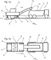
- FIGS. 1a and 1b illustrate a typical work situation of a milling device 1 in side view ( Fig. 1 a) and in plan view ( Fig. 1 b) ,
- the milling device 1 milled while milling soil material in the respective set milling depth FT and promotes this milled material (milled soil material) in the transport container 3 of a transport vehicle 2 (specifically, a semitrailer).
- the milling device 1 comprises a machine frame 4, a chassis 5 (comprising a total of four individual lifting columns with caterpillar nacelles), an operator workstation 6 and a milling rotor 8 mounted in a milling drum box 7, lying transversely to the working direction a of the milling apparatus 1 over the base 9 to be scoured emotional.
- the milled material is transported via a conveying device designed as a conveyor belt 10 from the milling device 1 to the transport vehicle 2.
- the conveyor belt 10 extends in the present embodiment to the front or in the working direction a and is obliquely forward and directed vertically upward from the machine frame 4 of the milling device 1 from.
- the conveying path of the milled material in the conveyor is in Fig.
- the transport container 3 is thus loaded from above by the ejected from the conveyor belt 10 milled material.
- the transport container 3 in this case has a front and a rear wall and corresponding side walls and a bottom and has a total of a substantially box-shaped appearance.
- the receiving space of the transport container 3 is bounded above by a peripheral upper edge 12.
- the milling device 1 moves in the milling operation at a nearly constant speed, however, relatively slowly in the direction of a.
- the transport vehicle 2 does not move at the same speed, but at intervals or in stop-and-go operation, as a continuous forward drive at the pace of the milling device would have severe wear on the transport vehicle 2 result.
- the transport vehicle In the In the working direction a forwardly unloading milling device 1, the transport vehicle is initially with the distance .DELTA.A max , measured here in the working direction a as the distance between the machine frame 4 and the rear side of the transport container 3, in the working direction a in front of the milling device 1.
- the milling operation moves the milling device 1 first on the transport vehicle 2 in the direction of a to, until the minimum distance ⁇ A min ( Fig. 1 b) is reached.
- the transport vehicle 2 then moves forward again when the minimum distance ⁇ A min is reached and stops as soon as the maximum exit distance ⁇ A max to the milling device 1 is reached again. Increases in relative and the distance between the milling device 1 and the transport vehicle 2 is thus reduced, as a rule several times between .DELTA.A max and min .DELTA.A during a loading operation.
- the minimum distance ⁇ A min and the maximum distance ⁇ A max are dimensioned such that on the one hand there is no collision between the two vehicles and at the same time the milled material as completely as possible and distributed over the entire length of the transport container 3 in the transport container 3 (over the top edge 12) is dropped.
- the sensor device a sensor camera 13 for detecting 3D or spatial information (specifically, a stereo-vision camera), which is arranged in the upper end region of the conveyor belt 10 with a view towards the transport vehicle 3.
- the sensor camera 13 is arranged so high that it is positioned above the upper edge 12 of the transport container 3.
- the sensor camera 13 is thus aligned on the conveyor belt 10 in such a way that it is aligned with its detection field in the filling opening of the transport container 3 (limited by the upper edge 12) into it.
- the detection field is the area that is detected by the sensor camera 13.
- the detection cone 14 of the sensor camera 13 is in the FIGS. 2a and 2b indicated by the dotted, gray underlying cone.
- the sensor camera 13 is in particular able to at least partially detect the upper edge 12 of the transport container 3 or to distinguish it from the environment and thus determine and track its relative position to the milling device 1. At the same time can be detected in the present embodiment by the special orientation of the sensor camera 13 at least in a partial area of the interior of the transport container 3, whereby the current level with milled material in the transport container 3 can be determined. In this case, the sensor camera 13 with its detection cone 14 does not detect the complete upper edge 12 of the transport container 3 and also not the complete receiving space of the transport container 3 but, depending on the distance of the milling device 1 from the transport vehicle 2, in each case a partial area.
- the sensor camera 13 is connected to a control unit 15, as shown in FIG Fig. 2a is exemplified by the dashed connection line 15 '.
- the control unit 15 receives the data determined by the sensor camera 13 and determines therefrom in more detail below the Intel Shellschreib the transport container 3.
- the control unit 15 coordinates in the present embodiment, the positioning of the transport vehicle 2 relative to the milling device 1 and controls to a display device 16 as a function of the relative distance of the transport vehicle 2 to the milling device 1.
- the functioning of the display device 16 is described below in FIG Fig. 6 further explained.
- FIGS. 3a, 3b and 3c illustrate the operation of the present device for controlling the loading process from the FIGS. 2a and 2b continue, where Fig. 3a the maximum distance ⁇ A max between the milling device 1 and transport vehicle 2 and Fig. 3b indicate the minimum distance ⁇ A min in each of the plan view. Fig. 3c Finally, the case in which the transport vehicle 2 is not yet or no longer within the loading area 17 of the milling device 1 is concerned. For reasons of clarity, the control unit 15 in the FIGS. 3a to 3c not specified.
- the loading area 17 is that area at the level of the upper edge 12 of the transport container 3, within which the milled material falls from the conveyor belt 10 into the transport container 3.
- the loading area 17 indicates the area into which the milled material coming from the conveyor belt 10 enters the receiving area of the transport container 3 bounded by the upper edge 12 to the sides. Only when at least part of the transport container 3 is in the loading area 17 or when the loading area is completely in the horizontal direction within the outer edges 12 of the transport container 3, the milled material from the conveyor belt 10 completely falls into the transport container 3.
- the loading area 17 is also displaced in relation to the transport vehicle 2 and in particular to the transport container 3 in order to enable the transfer of the material to be milled from conveyor belt 10 into the transport container 3 as completely as possible.
- the loading area 17 should ideally be located in the area of the transport container 3 because otherwise milled material falls next to the transport container 3.
- Fig. 3a indicates the maximum distance of the forward loading milling device 1 at. This is ultimately defined by the upper edge 12 of the rear wall 18 of the transport container 3 and their distance from the machine frame 4 of the milling device 1. If the distance between the milling device 1 and the transport vehicle 2 increases further, milled material falls next to the transport container 3 behind the transport vehicle 2. Der Minimum distance .DELTA.A min is reached when the milling device 1 has moved up far enough to the transport vehicle, that the upper edge 12 of the front wall 19 of the transport container adjacent to the loading area 17 (so that the milled material just just completely falls into the transport container 3) or the milling device. 1 moved so close to the transport vehicle 2 that there is just no collision between the two vehicles.
- the position of the loading area in practical use is not necessarily below the conveyor belt, but may for example also be offset forward in the discharge direction.
- the control unit 15 and the display device 16 in the FIGS. 3a to 3c not indicated separately, it is found that the milling device 1 swings relative to the transport vehicle 2 is for a full load between the maximum distance .DELTA.A max and the minimum distance .DELTA.A min, since the transport vehicle 2 is not uniform from the above-mentioned reasons, with the uniformly in the direction of a working milling device 1 is moved.
- the interval-like ancestor of the transport vehicle 2, triggered by reaching the minimum distance .DELTA.A min , up to the maximum distance .DELTA.A max is coordinated by the controlled by the control unit 15 display 16, so that the operator of the milling device 1 no longer has to pay attention to an appropriate spacing between the two vehicles in working mode.
- Fig. 3c Finally, it indicates the case in which the transport vehicle 2 is too far away from the milling device 1 or, in other words, no transport container 3 in the loading area 17 is detected by the sensor camera 13.
- the control unit 15 is designed in such a way that the loading process is not started automatically and rather in the concrete embodiment, a warning message is issued to the machine operator.
- the control of the milling device 1 is formed in such a way that the operator can start the operation of the conveyor belt 10 without the presence of a transport container 3 in the loading area 17 manually.
- the loading area 17 can also vary in size and be adapted to the individual circumstances. It is important that the loading area 17 a to the edge of the transport container 3 spaced, preferably in the working direction a center, ensures loading, so that the edge distribution of the material to be milled in the transport container 3 takes place essentially by gravity and trickle. Further details of the interaction between the sensor camera 13, the control unit 15 and the display device 16 are described below in the Fig. 6 specified further.
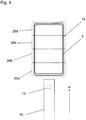
- Fig. 4 illustrates the operation for determining the BacchellShes of the transport container 3 in the event that the sensor device, specifically the sensor camera 13, not the transport container 3 detected in total, but rather only a partial section.
- the transport container 3 is virtually subdivided into the four subregions 20a to 20d, wherein alternatively, for example, also markings on the upper edge 12 of the transport container 3 for delimiting the subregions 20a to 20d and detection by the sensor camera 13 may be present. It goes without saying that the subdivision can also be much finer and even partially overlapping.
- the sensor camera 13 is designed in such a way that it respectively detects a partial section 20a, 20b, 20c or 20d when approaching the milling device 1 to the transport vehicle 2 in the working direction a, wherein the individual partial regions present in the order 20a, 20b, 20c, 20d to be run over when approaching the transport vehicle 2. If the transport vehicle 2 subsequently advances relative to the milling device up to the maximum distance ⁇ A max , the detection of the subregions 20a to 20d takes place in the reverse order. When detecting the partial area 20d, the minimum distance ⁇ A min between the milling device 1 and the transport vehicle 2 is reached.
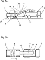
- FIGS. 5a and 5b relate to a further developed embodiment of the control unit 15.
- the control unit 15 of FIGS. 5a and 5b is not only designed to evaluate the data determined by the sensor camera 13, but at the same time to control certain machine functions.
- the machine controller 21 is essentially designed to control functions with regard to the positional orientation and the transport speed of the conveyor belt 10.
- the side deflection ⁇ Fig.
- the angle ⁇ as isverstellwinkel results from the adjustment of the longitudinal extent of the conveyor belt in the horizontal plane in relation to the longitudinal extent of the conveyor belt 10 in the working direction a.
- the angle ⁇ indicates the lowering or angle of attack of the conveyor belt 10 or its longitudinal extent in relation to a vertical vertical.
- Fig. 6 now the integration of the control unit 15 from the FIGS. 5a and 5b in the milling device 1 in detail.
- the control unit 15 thus initially detects the data determined by the sensor camera 13 and monitors the filling state of the transport container 3 on the basis of this data.
- the control unit 15 is also connected to the machine control unit 21.
- the control unit 15 receives information from the machine controller 21, for example with regard to the current operating state of the milling rotor 8 (in milling mode or off), with regard to the working or travel speed of the milling device 1, with regard to the conveying speed of the conveyor belt 10, etc.
- corresponding sensors connected via the machine control 21 to the control unit 15, which in Fig. 6 are indicated by the reference numeral 22.
- the control unit 15 determines whether the loading area 17 lies completely in the transport container 3 and, if so, whether regulation of the position of the conveyor belt, for example by the actuation of the actuators 23 (for vertical adjustment) and 24 (For the horizontal adjustment) and / or a regulation of the discharge width w via a control of the rotational speed of the conveyor belt (for example via a control of the motor controller 25 for the drive roller of the conveyor belt) is required.
- the control unit 15 further coordinates the optical display device 16 and an acoustic signaling device 26 to the driver of the transport vehicle 2, the commands “advance”, “stop” and “depart” depending on the distance of the transport container 3 to the milling device 1 indicate.
- Both the visual indicator 16 and the audible indicator 26 can operate independently of each other and are capable of "stopping" 27, “driving forward” 28 and “departing” 29 automatically in response to the results determined by the sensor device 13 in terms of location and filling state of the transport container 3 without own intervention by the machine operator of the milling device 1 display.
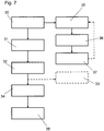
- Fig. 7 Finally, illustrates the essential steps for carrying out the method for controlling a loading operation of the transport container 3 of the transport vehicle 2 by the milling device 1 in the milling operation.
- step 30 the relative position of the transport container 3 is initially detected in the loading area 17 of the milling device 1 with the aid of the sensor camera 13.
- the sensor device 13 determines in other words whether the loading area lies inside the transport container 3 and milling material is thus completely in the transport container 3 would be promoted.
- the control unit 15 determines that the loading area 17 is within the upper edge 12 of the transport container 3, the control unit 15 starts the loading operation by putting the conveyor belt 10 into operation according to step 31 and / or, in an alternative embodiment, to the machine operator of the milling device in that the loading process can be started.
- the control unit 15 uses the sensor camera 13 to monitor the relative position of the transport container in accordance with step 32 over the loading process and controls the loading operation as a function of the relative position of the transport container 3.
- the loading process can initially be controlled in such a way that the control unit 15 controls the loading operation Conveyor belt 10 automatically shuts off when the loading area 17 is no longer within the bounded by the top edge 12 receiving opening of the transport container 3 or the machine operator of the milling device is a corresponding signal.
- controlling the loading process according to step 33 also includes the regulation of further operating parameters, such as the position of the conveyor belt in the horizontal plane and its inclination and the control of the rotational speed of the conveyor belt 10 to regulate the discharge of the milled material at the exit the conveyor belt 10.
- the control unit determines the achievement of the desired filling of the transport container, it preferably signals this to the machine operator of the milling device 1 and / or, depending on the embodiment, automatically stops the loading process according to step 34.
- the control unit 15 simultaneously assumes in Fig. 7 In the embodiment shown, the control of the signal device 16 and / or 26, wherein initially to step 30, the achievement of the minimum distance .DELTA.A min according to step 35 is awaited.
- the control unit 15 then outputs via the signal device 26 and / or 16 the command "drive forward" 28 according to step 36 until the maximum distance between the milling device 1 and the transport vehicle 2 ⁇ A max is reached.
- the control unit 15 in step 37 signals "stop" 27 and thus gives the driver of the transport vehicle 2 the command to stop.
- the sequence of steps 35 to 37 may be repeated several times, as in Fig. 7 indicated by the dashed line.
- the control unit 15 according to step 38 via the signal devices 16 and / or 26, the command "depart” 29 to the driver of the transport vehicle 2 the Signal completion of the filling process.
Landscapes
- Engineering & Computer Science (AREA)
- Architecture (AREA)
- Civil Engineering (AREA)
- Structural Engineering (AREA)
- Mechanical Engineering (AREA)
- Mining & Mineral Resources (AREA)
- Loading Or Unloading Of Vehicles (AREA)
- Road Repair (AREA)
Claims (17)
- Procédé de commande d'un processus de chargement d'un conteneur de transport (3) d'un véhicule de transport (2) par un dispositif de fraisage (1) pendant une opération de fraisage, le dispositif de fraisage (1) comprenant un dispositif convoyeur (10), au moyen duquel le fraisat est amené dans le conteneur de transport (3) pendant l'opération de fraisage du dispositif de fraisage (1), et une unité de commande (15),
caractérisé par les étapes de:a) détection (30) de la position relative du conteneur de transport (3) dans la zone de chargement (17) du dispositif de fraisage (1) au moyen d'un dispositif détecteur (13) ;b) lancement (31) du processus de chargement par la mise en marche du dispositif convoyeur (10);c) surveillance (32) de la position relative du conteneur de transport (3) au moyen du dispositif détecteur (13); etd) émission d'un signal lorsqu'un niveau de remplissage déterminé du conteneur de transport (3) est atteint et/ou dès que le dispositif détecteur détecte un retrait du conteneur de transport (3) de la zone de chargement (17), en particulier l'arrêt (34) du processus de chargement,le processus de chargement étant commandé à l'étape c) par la détection de la trajectoire de déversement du fraisat déversé du dispositif convoyeur (10) dans le conteneur de transport (3) et le contrôle en boucle fermée de la distance de déversement de la trajectoire de déversement, en particulier par réglage de la vitesse de fonctionnement du dispositif convoyeur (10), par ajustement de la hauteur du dispositif convoyeur (10) et/ou par ajustement de l'angle d'orientation du dispositif convoyeur (10). - Procédé selon la revendication 1,
caractérisé en ce que
à l'étape c) les étapes de procédé suivantes prennent place:1.) détection d'au moins une zone partielle (20a, 20b, 20c, 20d) du conteneur de transport (3), en particulier d'une partie du bord supérieur (12) du conteneur de transport (3), et détermination de l'état de remplissage dans cette zone partielle (20a, 20b, 20c, 20d) du conteneur de transport (3);2.) enregistrement de l'état de remplissage détecté à l'étape 1.) dans ladite au moins une zone partielle (20a, 20b, 20c, 20d);3.) détection d'une autre zone partielle (20a, 20b, 20c, 20d) du conteneur de transport (3), détermination de l'état de remplissage dans cette autre zone partielle (20a, 20b, 20c, 20d) et enregistrement de l'état de remplissage détecté de l'autre zone partielle (20a, 20b, 20c, 20d);4.) détermination du niveau de remplissage total au moyen des données actuellement déterminées à l'étape 3.) et des dernière données stockées à l'étape 2.);5.) mise à jour des niveaux de remplissage des zones partielles déjà détectées (20a, 20b, 20c, 20d) du conteneur de transport (3); et6.) détermination du degré de remplissage du conteneur de transport sur la base des derniers niveaux de remplissage respectifs concernant les zones partielles individuelles du conteneur de transport. - Procédé selon l'une quelconque des revendications précédentes,
caractérisé en ce que
l'étape c) comprend- le contrôle en boucle fermée de la déviation latérale de la trajectoire de décharge par rapport au conteneur de décharge (3) par un réglage latéral du dispositif convoyeur (10). - Procédé selon l'une quelconque des revendications précédentes,
caractérisé en ce que
l'unité de commande (15), en fonction du degré de chargement du conteneur de transport et/ou de la distance entre le dispositif de fraisage (1) et le véhicule de transport (2), commande un dispositif de signalisation (16) qui donne au moins un signal respectif pour les instructions "marche avant" (28), "arrêt" (27) et "départ" (29). - Procédé selon l'une quelconque des revendications précédentes,
caractérisé enceque
l'unité de commande (15) commande le mouvement de déplacement du véhicule de transport (2) pendant l'opération de chargement. - Procédé selon l'une quelconque des revendications précédentes,
caractérisé en ce que
l'unité de commande (15) commande le dispositif de signalisation (16) ou le véhicule de transport (2) en fonction d'une détection alternée du bord supérieur avant ou arrière (12) du conteneur de transport (3). - Procédé selon l'une quelconque des revendications précédentes,
caractérisé en ce que
l'unité de commande (15) prend en considération au moins l'un des paramètres de fonctionnement suivants du dispositif de fraisage (1) pour contrôler le processus de chargement:- vitesse de déplacement du dispositif de fraisage (1) pendant l'opération de fraisage;- activation d'un rotor de fraisage (8);- profondeur de fraisage d'un rotor de fraisage (8);- statut opérationnel du dispositif convoyeur (10);- vitesse de transport d'une courroie transporteuse (10) du dispositif convoyeur;- angle de réglage latéral de la courroie transporteuse (10); ou- angle d'inclinaison de la courroie transporteuse (10). - Dispositif de commande d'un processus de chargement d'un conteneur de transport (3) d'un véhicule de transport (2) par un dispositif de fraisage (1) pendant une opération de fraisage, le dispositif de fraisage (1) comprenant un dispositif convoyeur (10), au moyen duquel le fraisat est amené dans le conteneur de transport (3) pendant l'opération de fraisage du dispositif de fraisage (1),
le dispositif comprenant un dispositif détecteur (13) configuré pour détecter la position relative du conteneur de transport (3) par rapport au dispositif de fraisage (1),
caractérisé en ce que
le dispositif comprend une unité de commande (15), qui commande le processus de chargement sur la base de la position relative du conteneur de transport (3) par rapport au dispositif de fraisage (1) détectée par le dispositif détecteur (13) et qui surveille la position relative du conteneur de transport (3), le processus de chargement étant contrôlé par la détection de la trajectoire de déversement du fraisat déversé du dispositif convoyeur (10) dans le conteneur de transport (3) et par le réglage de la distance de déversement de la trajectoire de décharge, en particulier par le réglage de la vitesse de fonctionnement du dispositif convoyeur (10), par ajustement de la hauteur du dispositif convoyeur (10) et/ou par ajustement de l'angle d'orientation du dispositif convoyeur (10). - Dispositif de commande d'un processus de chargement selon la revendication 8,
caractérisé en ce que
le dispositif détecteur est configuré pour détecter au moins une zone partielle (20a, 20b, 20c, 20d) du bord supérieur (12) du conteneur de transport (3). - Dispositif de commande d'un processus de chargement selon l'une quelconque des revendications 8 ou 9,
caractérisé en ce que
le dispositif détecteur comprend un dispositif de prises de vues (13) qui est configuré pour détecter des informations en 3D. - Dispositif de commande d'un processus de chargement selon la revendication 10,
caractérisé en ce que
le dispositif de prises de vues (13) comprend un dispositif électro-optique avec une caméra à capteurs, en particulier une caméra à stéréovision (13) ou une caméra à capteurs avec un capteur PMD. - Dispositif de commande d'un processus de chargement selon l'une quelconque des revendications 8 à 11,
caractérisé en ce que
le dispositif convoyeur comprend une courroie transporteuse (10) et un châssis de support, et en ce que le dispositif détecteur est fixé sur le châssis de support, en particulier dans la zone d'extrémité supérieure du châssis de support. - Dispositif de commande d'un processus de chargement selon l'une quelconque des revendications 8 à 12,
caractérisé en ce que
un dispositif de signalisation actionné par l'unité de commande (15) est présent, qui est configuré pour produire au moins les trois fonctions de commande "marche avant" (28), "arrêt" (27) et "départ" (29). - Dispositif de commande d'un processus de chargement selon la revendication 13,
caractérisé en ce que
le dispositif de signalisation comprend un élément de production optique et/ou acoustique (16) pour produire lesdites au moins trois fonctions de commande (27, 28, 29). - Dispositif de commande d'un processus de chargement selon l'une quelconque des revendications 8 à 14,
caractérisé en ce que
l'unité de commande (15) comprend un élément de mémoire, en particulier une mémoire à enregistrement continu, l'élément de mémoire étant configuré pour enregistrer les données fournies par le dispositif détecteur et pour enregistrer les dernières données concernant la zone partielle respective (20a, 20b, 20c, 20d) du conteneur de transport (3). - Dispositif de commande d'un processus de chargement selon l'une quelconque des revendications 8 à 15,
caractérisé enceque
un dispositif d'actionnement est pourvu d'un moyen d'actionnement qui est placé à portée d'un opérateur du dispositif de fraisage (1), le dispositif d'actionnement étant configuré de telle sorte que des commandes de contrôle, en particulier pour l'activation et la désactivation du dispositif, peuvent être entrées grâce à des moyens d'actionnement et transférées à l'unité de commande (15) par l'intermédiaire du dispositif d'actionnement. - Fraiseuse, en particulier engin de fraisage de chaussées ou dispositif pour enlever des couches de terre, avec un dispositif selon l'une quelconque des revendications 8 à 16, en particulier pour mettre en oeuvre un procédé selon l'une quelconque des revendications 1 à 7.
Applications Claiming Priority (1)
| Application Number | Priority Date | Filing Date | Title |
|---|---|---|---|
| DE102011114183A DE102011114183A1 (de) | 2011-09-22 | 2011-09-22 | Verfahren zur Steuerung eines Beladungsvorgangs eines Transportfahrzeugs mit Fräsgut, Vorrichtung zur Durchführung eines solchen Verfahrens und Fräsvorrichtung |
Publications (3)
| Publication Number | Publication Date |
|---|---|
| EP2573266A2 EP2573266A2 (fr) | 2013-03-27 |
| EP2573266A3 EP2573266A3 (fr) | 2015-09-30 |
| EP2573266B1 true EP2573266B1 (fr) | 2017-02-15 |
Family
ID=47008224
Family Applications (1)
| Application Number | Title | Priority Date | Filing Date |
|---|---|---|---|
| EP12006594.1A Active EP2573266B1 (fr) | 2011-09-22 | 2012-09-20 | Procédé de commande d'un procédé de chargement d'un véhicule de transport avec des produits de fraisage, dispositif destiné à réaliser un tel procédé et dispositif de fraisage |
Country Status (3)
| Country | Link |
|---|---|
| US (1) | US9562334B2 (fr) |
| EP (1) | EP2573266B1 (fr) |
| DE (1) | DE102011114183A1 (fr) |
Cited By (1)
| Publication number | Priority date | Publication date | Assignee | Title |
|---|---|---|---|---|
| US11472434B2 (en) * | 2019-03-06 | 2022-10-18 | Hiab Ab | Vehicle comprising a vehicle accessory arrangement |
Families Citing this family (42)
| Publication number | Priority date | Publication date | Assignee | Title |
|---|---|---|---|---|
| DE102008008260B4 (de) * | 2008-02-08 | 2010-09-09 | Wirtgen Gmbh | Steuerung einer Gewinnungsmaschine und Gewinnungsmaschine |
| DE102009041842A1 (de) | 2009-09-18 | 2011-09-01 | Wirtgen Gmbh | Selbstfahrende Straßenfräsmaschine |
| US9045072B2 (en) * | 2009-11-02 | 2015-06-02 | Super Products Llc | Debris level indicator in vacuum loaded mobile tanks |
| DE102012215013A1 (de) | 2012-08-23 | 2014-02-27 | Wirtgen Gmbh | Selbstfahrende Fräsmaschine, sowie Verfahren zum Abladen von Fräsgut |
| DE102012215005A1 (de) * | 2012-08-23 | 2014-02-27 | Wirtgen Gmbh | Selbstfahrende Fräsmaschine, sowie Verfahren zum Lenken einer selbstfahrenden Fräsmaschine |
| DE102012020655A1 (de) * | 2012-10-19 | 2014-04-24 | Wirtgen Gmbh | Selbstfahrende Baumaschine |
| DE102012022732B4 (de) | 2012-11-21 | 2024-07-18 | Bomag Gmbh | Baumaschine mit einer Arbeitseinrichtung zur Bodenuntergrundbearbeitung und Verfahren zum Betrieb einer solchen Baumaschine |
| DE102013009361B4 (de) | 2013-06-04 | 2018-07-12 | Bomag Gmbh | Bodenfräsmaschine mit einer Anbauförderbandsteuerung, Anbauförderbandsteuerung für eine Bodenfräsmaschine sowie Verfahren zur Steuerung eines Anbauförderbandes einer Bodenfräsmaschine |
| WO2015034501A1 (fr) * | 2013-09-05 | 2015-03-12 | Volvo Construction Equipment Ab | Système de contrôle de surcharge de convoyeur pour engin de chantier |
| DE102014216603B4 (de) | 2014-08-21 | 2018-02-22 | Wirtgen Gmbh | Selbstfahrende Fräsmaschine, sowie Verfahren zum Abladen von Fräsgut |
| DE102014216763B4 (de) | 2014-08-22 | 2018-07-26 | Wirtgen Gmbh | Selbstfahrende Fräsmaschine, sowie Verfahren zum Abladen von Fräsgut |
| DE102014216713B4 (de) | 2014-08-22 | 2018-09-06 | Wirtgen Gmbh | Selbstfahrende Fräsmaschine, sowie Verfahren zum Abladen von Fräsgut |
| DE102015005194A1 (de) | 2014-12-19 | 2016-06-23 | Bomag Gmbh | Verfahren zur Fräsgutmassenbestimmung und Bodenfräsmaschine zur Durchführung des Verfahrens |
| WO2016178294A1 (fr) * | 2015-05-07 | 2016-11-10 | ヤンマー株式会社 | Système de commande d'induction pour véhicule à déplacement autonome |
| US9938674B2 (en) | 2015-05-27 | 2018-04-10 | Caterpillar Paving Products Inc. | Cold planer transport payload monitoring system |
| US9957675B2 (en) * | 2015-07-10 | 2018-05-01 | Caterpillar Paving Products Inc. | Cold planer loading and transport control system |
| US10380529B2 (en) * | 2015-08-17 | 2019-08-13 | Caterpillar Paving Products Inc. | Cold planer material transport management system |
| US9738202B2 (en) * | 2015-09-10 | 2017-08-22 | Caterpillar Inc. | Regulating dump rate of trucks |
| US20170130405A1 (en) * | 2015-11-05 | 2017-05-11 | Caterpillar Paving Products Inc. | Truck position control system for milling operations |
| DE102016003674B4 (de) | 2015-12-23 | 2023-05-25 | Bomag Gmbh | Baumaschine mit magnetischer Schnellmontageeinheit und Verfahren |
| CN108473260B (zh) * | 2016-01-21 | 2022-08-12 | 维特根有限公司 | 包括建筑机械、具有装载空间的运输车辆和图像记录装置的系统以及用于在运输车辆的装载或卸载期间显示图像流的方法 |
| US10688901B2 (en) * | 2016-03-23 | 2020-06-23 | Bomag Gmbh | Intermediate storage vehicle for milled material and work train |
| DE102016003562B4 (de) | 2016-03-23 | 2022-09-22 | Bomag Gmbh | Fräszug sowie Verfahren |
| US10927513B2 (en) | 2016-11-11 | 2021-02-23 | Wirtgen Gmbh | System and method for the tracking of milling material |
| DE102016222145A1 (de) | 2016-11-11 | 2018-05-17 | Wirtgen Gmbh | System und Verfahren zum Nachverfolgen von Fräsgut |
| DE102016223454A1 (de) | 2016-11-25 | 2018-05-30 | Wirtgen Gmbh | System und Verfahren zum Nachverfolgen von Fräsgut |
| DE102016222589B4 (de) | 2016-11-16 | 2020-01-16 | Wirtgen Gmbh | Selbstfahrende Fräsmaschine, sowie Verfahren zum Steuern einer selbstfahrenden Fräsmaschine |
| CN107161585A (zh) * | 2017-07-24 | 2017-09-15 | 合肥星袖机械科技有限公司 | 一种物料自动运输控制系统 |
| DE102017220869A1 (de) * | 2017-11-22 | 2019-05-23 | Wirtgen Gmbh | Selbstfahrende Fräsmaschine, Verfahren zum automatischen Beladen eines Transportmittels mit Fräsgut, sowie Straßen- oder Bodenbearbeitungseinheit |
| DE102017011159A1 (de) * | 2017-12-04 | 2019-06-06 | Dynapac Gmbh | Straßenbaumaschine und Verfahren zum Betreiben einer Straßenbaumaschine |
| CN108221610A (zh) * | 2018-03-14 | 2018-06-29 | 徐州徐工筑路机械有限公司 | 一种基于视觉识别的铣刨机自动输料系统 |
| US11149407B2 (en) | 2018-12-06 | 2021-10-19 | Caterpillar Inc. | Earth-moving machinery collision threat filtering |
| US11232712B2 (en) | 2019-01-03 | 2022-01-25 | Caterpillar Paving Products Inc. | Paver haul truck grouping |
| US11498785B2 (en) * | 2019-01-30 | 2022-11-15 | Caterpillar Inc. | System and method of automated clean out of carryback in surface haulage |
| US11560676B2 (en) | 2019-02-13 | 2023-01-24 | Caterpillar Paving Products Inc. | Determine optimal frequency to load haul truck |
| DE102019104218A1 (de) | 2019-02-19 | 2020-08-20 | Wirtgen Gmbh | Arbeitszug, umfassend eine Bodenbearbeitungsmaschine und ein weiteres Fahrzeug sowie eine automatisierte Abstandsüberwachung |
| DE102020002161A1 (de) | 2020-04-03 | 2021-10-07 | Bomag Gmbh | Straßenfräsmaschine, Anbaueinheit zur Verwendung in einer Straßenfräsmaschine sowie Verfahren zum Betrieb einer Straßenfräsmaschine |
| DE102020007112A1 (de) | 2020-11-20 | 2022-05-25 | Bomag Gmbh | VERFAHREN ZUR STEUERUNG DES BETRIEBS EINES AN EINER SELBSTFAHRENDEN STRAßENBAU- ODER TAGEBAUMASCHINE ANGEORDNETEN VERLADEFÖRDERBANDES FÜR SCHÜTTGUT RELATIV ZU EINER TRANSPORTMULDE EINES TRANSPORTFAHRZEUGS SOWIE STRAßENBAU- ODER TAGEBAUMASCHINE ZUR DURCHFÜHRUNG DES VERFAHRENS |
| US11845622B2 (en) | 2020-12-11 | 2023-12-19 | Caterpillar Paving Products Inc. | Truck measurement of a milling machine |
| US12036958B2 (en) * | 2021-09-17 | 2024-07-16 | Deere & Company | Selectively implementing automated cleaning routines during unloading cycles for transport vehicles |
| US20230349109A1 (en) * | 2022-04-27 | 2023-11-02 | Caterpillar Paving Products Inc. | System and method for controlling alignment of machines during operations |
| DE102022205561A1 (de) | 2022-05-31 | 2023-11-30 | Bomag Gmbh | VERFAHREN ZUM BEFÜLLEN EINES TRANSPORTBEHÄLTERS MIT FRÄSGUT IN EINEM ARBEITSZUG MIT EINER STRAßENFRÄSMASCHINE UND EINEM TRANSPORTFAHRZEUG, ARBEITZUG, STRAßENFRÄSMASCHINE, TRANSPORTFAHRZEUG UND NACHRÜSTSATZ |
Family Cites Families (8)
| Publication number | Priority date | Publication date | Assignee | Title |
|---|---|---|---|---|
| DE4403893A1 (de) | 1994-02-08 | 1995-08-10 | Claas Ohg | Vorrichtung zur automatischen Befüllung von Ladebehältern mit einem Gutstrom |
| DE102004011789A1 (de) * | 2004-03-09 | 2005-09-29 | Claas Selbstfahrende Erntemaschinen Gmbh | Vorrichtung zum Erfassen eines Ladewagens |
| DE102005035480A1 (de) * | 2005-07-26 | 2007-02-01 | Cft Gmbh Compact Filter Technic | Fräsmaschine für Straßenbeläge mit Entstaubung |
| DE112008000646T5 (de) * | 2007-03-20 | 2010-05-12 | Volvo Construction Equipment Ab | Fräsmaschine mit Schneidtrommel-Geschwindigkeitssteuerung |
| DE102008008260B4 (de) | 2008-02-08 | 2010-09-09 | Wirtgen Gmbh | Steuerung einer Gewinnungsmaschine und Gewinnungsmaschine |
| EP2311307B1 (fr) * | 2009-09-07 | 2011-12-07 | CLAAS Agrosystems GmbH & Co. KG | Jauge de remplissage, véhicule agricole doté d'une telle jauge et procédé de commande de remplissage d'une région cible |
| DE102009041842A1 (de) | 2009-09-18 | 2011-09-01 | Wirtgen Gmbh | Selbstfahrende Straßenfräsmaschine |
| US8380401B2 (en) * | 2010-06-09 | 2013-02-19 | Cnh America Llc | Automatic grain transfer control system based on real time modeling of a fill level profile for regions of the receiving container |
-
2011
- 2011-09-22 DE DE102011114183A patent/DE102011114183A1/de active Pending
-
2012
- 2012-09-20 EP EP12006594.1A patent/EP2573266B1/fr active Active
- 2012-09-21 US US13/624,586 patent/US9562334B2/en active Active
Non-Patent Citations (1)
| Title |
|---|
| None * |
Cited By (1)
| Publication number | Priority date | Publication date | Assignee | Title |
|---|---|---|---|---|
| US11472434B2 (en) * | 2019-03-06 | 2022-10-18 | Hiab Ab | Vehicle comprising a vehicle accessory arrangement |
Also Published As
| Publication number | Publication date |
|---|---|
| US9562334B2 (en) | 2017-02-07 |
| DE102011114183A1 (de) | 2013-03-28 |
| EP2573266A3 (fr) | 2015-09-30 |
| EP2573266A2 (fr) | 2013-03-27 |
| US20130080000A1 (en) | 2013-03-28 |
Similar Documents
| Publication | Publication Date | Title |
|---|---|---|
| EP2573266B1 (fr) | Procédé de commande d'un procédé de chargement d'un véhicule de transport avec des produits de fraisage, dispositif destiné à réaliser un tel procédé et dispositif de fraisage | |
| EP2573267B2 (fr) | Train de traveaux avec un dispositif de fraisage et une installation de transport et un dispositif de capteur pour la surveillance à distance, dispositif de fraisage avec un dispositif de capteur et procédé de surveillance à distance avec un train de traveaux | |
| EP3563667B1 (fr) | Procédé de distribution de produit de récolte | |
| EP1219158B2 (fr) | Dispositif pour optimiser le transbordement de produits de récolte à un véhicule agricole | |
| EP3289852B2 (fr) | Véhicule de transport | |
| EP2510775B1 (fr) | Système et procédé de commande du transfert de récoltes | |
| EP1977640B1 (fr) | Moissonneuse agricole automobile dotée d'un dispositif de transbordement réglable | |
| EP1645178B1 (fr) | Système d'assistance pour le transfert | |
| EP1219153B1 (fr) | Dispositif et méthode pour coordonner et contrôler des véhicules agricoles | |
| EP2987911B1 (fr) | Fraiseuse automobile, et procede d'evacuation de produit de fraisage | |
| EP2995191A1 (fr) | Procédé de commande d'un processus de transbordement | |
| WO2016078757A1 (fr) | Véhicule autonome, en particulier mélangeuse, et procédé de commande d'un véhicule autonome | |
| DE102011121414A1 (de) | Verfahren und eine Vorrichtung zur Regelung einer Fahrt einer ersten selbstfahrenden Arbeitsmaschine in Bezug zu einer zweiten selbstfahrenden Arbeitsmaschine | |
| DE102005004508A1 (de) | Vorrichtung zur gleichmäßigen Beschickung von Arbeitsmaschinen | |
| WO2020135923A1 (fr) | Procédé de régulation de la hauteur d'un panneau latéral d'une machine de fraisage du sol, et machine de fraisage du sol | |
| DE102017012124A1 (de) | Verfahren zur Steuerung der Höhenlage eines Niederhalters einer Bodenfräsmaschine und Bodenfräsmaschine | |
| DE102013009361B4 (de) | Bodenfräsmaschine mit einer Anbauförderbandsteuerung, Anbauförderbandsteuerung für eine Bodenfräsmaschine sowie Verfahren zur Steuerung eines Anbauförderbandes einer Bodenfräsmaschine | |
| EP4001507B1 (fr) | Procédé de commande du fonctionnement d'une bande transporteuse de chargement pour marchandises en vrac disposée sur une machine autonome de construction de route ou d'exploitation minière de surface par rapport à un benne d'un véhicule de transport, ainsi que machine de construction de route ou d'exploitation minière de surface destinée à la mise en oeuvre du procédé | |
| DE102017002641A1 (de) | Zwischenspeicherfahrzeug für Fräsgut und Arbeitszug | |
| DE102019207259B4 (de) | System und Verfahren zur Absturzsicherung eines Fahrzeugs | |
| EP3456584B1 (fr) | Véhicule de transport de charges et son procédé de fonctionnement | |
| DE102016002294B4 (de) | Bodenfräsmaschine, Verfahren zum Steuern einer Sicherheitsabschalteinrichtung einer Fräswalze einer Bodenfräsmaschine und Steuereinheit | |
| DE102022205561A1 (de) | VERFAHREN ZUM BEFÜLLEN EINES TRANSPORTBEHÄLTERS MIT FRÄSGUT IN EINEM ARBEITSZUG MIT EINER STRAßENFRÄSMASCHINE UND EINEM TRANSPORTFAHRZEUG, ARBEITZUG, STRAßENFRÄSMASCHINE, TRANSPORTFAHRZEUG UND NACHRÜSTSATZ | |
| EP2108248B1 (fr) | Ramasseuse-hacheuse et dispositif d'introduction pour une ramasseuse-hacheuse | |
| DE102017011159A1 (de) | Straßenbaumaschine und Verfahren zum Betreiben einer Straßenbaumaschine |
Legal Events
| Date | Code | Title | Description |
|---|---|---|---|
| PUAI | Public reference made under article 153(3) epc to a published international application that has entered the european phase |
Free format text: ORIGINAL CODE: 0009012 |
|
| AK | Designated contracting states |
Kind code of ref document: A2 Designated state(s): AL AT BE BG CH CY CZ DE DK EE ES FI FR GB GR HR HU IE IS IT LI LT LU LV MC MK MT NL NO PL PT RO RS SE SI SK SM TR |
|
| AX | Request for extension of the european patent |
Extension state: BA ME |
|
| PUAL | Search report despatched |
Free format text: ORIGINAL CODE: 0009013 |
|
| AK | Designated contracting states |
Kind code of ref document: A3 Designated state(s): AL AT BE BG CH CY CZ DE DK EE ES FI FR GB GR HR HU IE IS IT LI LT LU LV MC MK MT NL NO PL PT RO RS SE SI SK SM TR |
|
| AX | Request for extension of the european patent |
Extension state: BA ME |
|
| RIC1 | Information provided on ipc code assigned before grant |
Ipc: E01C 23/088 20060101AFI20150826BHEP |
|
| 17P | Request for examination filed |
Effective date: 20160318 |
|
| RBV | Designated contracting states (corrected) |
Designated state(s): AL AT BE BG CH CY CZ DE DK EE ES FI FR GB GR HR HU IE IS IT LI LT LU LV MC MK MT NL NO PL PT RO RS SE SI SK SM TR |
|
| GRAP | Despatch of communication of intention to grant a patent |
Free format text: ORIGINAL CODE: EPIDOSNIGR1 |
|
| INTG | Intention to grant announced |
Effective date: 20160901 |
|
| GRAS | Grant fee paid |
Free format text: ORIGINAL CODE: EPIDOSNIGR3 |
|
| GRAA | (expected) grant |
Free format text: ORIGINAL CODE: 0009210 |
|
| AK | Designated contracting states |
Kind code of ref document: B1 Designated state(s): AL AT BE BG CH CY CZ DE DK EE ES FI FR GB GR HR HU IE IS IT LI LT LU LV MC MK MT NL NO PL PT RO RS SE SI SK SM TR |
|
| REG | Reference to a national code |
Ref country code: CH Ref legal event code: EP Ref country code: GB Ref legal event code: FG4D Free format text: NOT ENGLISH |
|
| REG | Reference to a national code |
Ref country code: IE Ref legal event code: FG4D Free format text: LANGUAGE OF EP DOCUMENT: GERMAN |
|
| REG | Reference to a national code |
Ref country code: AT Ref legal event code: REF Ref document number: 867973 Country of ref document: AT Kind code of ref document: T Effective date: 20170315 |
|
| REG | Reference to a national code |
Ref country code: DE Ref legal event code: R096 Ref document number: 502012009523 Country of ref document: DE |
|
| REG | Reference to a national code |
Ref country code: NL Ref legal event code: FP |
|
| REG | Reference to a national code |
Ref country code: SE Ref legal event code: TRGR |
|
| REG | Reference to a national code |
Ref country code: NO Ref legal event code: T2 Effective date: 20170215 |
|
| REG | Reference to a national code |
Ref country code: LT Ref legal event code: MG4D |
|
| PG25 | Lapsed in a contracting state [announced via postgrant information from national office to epo] |
Ref country code: LT Free format text: LAPSE BECAUSE OF FAILURE TO SUBMIT A TRANSLATION OF THE DESCRIPTION OR TO PAY THE FEE WITHIN THE PRESCRIBED TIME-LIMIT Effective date: 20170215 Ref country code: FI Free format text: LAPSE BECAUSE OF FAILURE TO SUBMIT A TRANSLATION OF THE DESCRIPTION OR TO PAY THE FEE WITHIN THE PRESCRIBED TIME-LIMIT Effective date: 20170215 Ref country code: GR Free format text: LAPSE BECAUSE OF FAILURE TO SUBMIT A TRANSLATION OF THE DESCRIPTION OR TO PAY THE FEE WITHIN THE PRESCRIBED TIME-LIMIT Effective date: 20170516 Ref country code: HR Free format text: LAPSE BECAUSE OF FAILURE TO SUBMIT A TRANSLATION OF THE DESCRIPTION OR TO PAY THE FEE WITHIN THE PRESCRIBED TIME-LIMIT Effective date: 20170215 |
|
| PG25 | Lapsed in a contracting state [announced via postgrant information from national office to epo] |
Ref country code: LV Free format text: LAPSE BECAUSE OF FAILURE TO SUBMIT A TRANSLATION OF THE DESCRIPTION OR TO PAY THE FEE WITHIN THE PRESCRIBED TIME-LIMIT Effective date: 20170215 Ref country code: PT Free format text: LAPSE BECAUSE OF FAILURE TO SUBMIT A TRANSLATION OF THE DESCRIPTION OR TO PAY THE FEE WITHIN THE PRESCRIBED TIME-LIMIT Effective date: 20170615 Ref country code: RS Free format text: LAPSE BECAUSE OF FAILURE TO SUBMIT A TRANSLATION OF THE DESCRIPTION OR TO PAY THE FEE WITHIN THE PRESCRIBED TIME-LIMIT Effective date: 20170215 Ref country code: ES Free format text: LAPSE BECAUSE OF FAILURE TO SUBMIT A TRANSLATION OF THE DESCRIPTION OR TO PAY THE FEE WITHIN THE PRESCRIBED TIME-LIMIT Effective date: 20170215 Ref country code: BG Free format text: LAPSE BECAUSE OF FAILURE TO SUBMIT A TRANSLATION OF THE DESCRIPTION OR TO PAY THE FEE WITHIN THE PRESCRIBED TIME-LIMIT Effective date: 20170515 |
|
| REG | Reference to a national code |
Ref country code: FR Ref legal event code: PLFP Year of fee payment: 6 |
|
| PG25 | Lapsed in a contracting state [announced via postgrant information from national office to epo] |
Ref country code: IT Free format text: LAPSE BECAUSE OF FAILURE TO SUBMIT A TRANSLATION OF THE DESCRIPTION OR TO PAY THE FEE WITHIN THE PRESCRIBED TIME-LIMIT Effective date: 20170215 Ref country code: CZ Free format text: LAPSE BECAUSE OF FAILURE TO SUBMIT A TRANSLATION OF THE DESCRIPTION OR TO PAY THE FEE WITHIN THE PRESCRIBED TIME-LIMIT Effective date: 20170215 Ref country code: RO Free format text: LAPSE BECAUSE OF FAILURE TO SUBMIT A TRANSLATION OF THE DESCRIPTION OR TO PAY THE FEE WITHIN THE PRESCRIBED TIME-LIMIT Effective date: 20170215 Ref country code: SK Free format text: LAPSE BECAUSE OF FAILURE TO SUBMIT A TRANSLATION OF THE DESCRIPTION OR TO PAY THE FEE WITHIN THE PRESCRIBED TIME-LIMIT Effective date: 20170215 Ref country code: EE Free format text: LAPSE BECAUSE OF FAILURE TO SUBMIT A TRANSLATION OF THE DESCRIPTION OR TO PAY THE FEE WITHIN THE PRESCRIBED TIME-LIMIT Effective date: 20170215 |
|
| REG | Reference to a national code |
Ref country code: DE Ref legal event code: R097 Ref document number: 502012009523 Country of ref document: DE |
|
| PG25 | Lapsed in a contracting state [announced via postgrant information from national office to epo] |
Ref country code: SM Free format text: LAPSE BECAUSE OF FAILURE TO SUBMIT A TRANSLATION OF THE DESCRIPTION OR TO PAY THE FEE WITHIN THE PRESCRIBED TIME-LIMIT Effective date: 20170215 Ref country code: PL Free format text: LAPSE BECAUSE OF FAILURE TO SUBMIT A TRANSLATION OF THE DESCRIPTION OR TO PAY THE FEE WITHIN THE PRESCRIBED TIME-LIMIT Effective date: 20170215 Ref country code: DK Free format text: LAPSE BECAUSE OF FAILURE TO SUBMIT A TRANSLATION OF THE DESCRIPTION OR TO PAY THE FEE WITHIN THE PRESCRIBED TIME-LIMIT Effective date: 20170215 |
|
| PLBE | No opposition filed within time limit |
Free format text: ORIGINAL CODE: 0009261 |
|
| STAA | Information on the status of an ep patent application or granted ep patent |
Free format text: STATUS: NO OPPOSITION FILED WITHIN TIME LIMIT |
|
| 26N | No opposition filed |
Effective date: 20171116 |
|
| PG25 | Lapsed in a contracting state [announced via postgrant information from national office to epo] |
Ref country code: SI Free format text: LAPSE BECAUSE OF FAILURE TO SUBMIT A TRANSLATION OF THE DESCRIPTION OR TO PAY THE FEE WITHIN THE PRESCRIBED TIME-LIMIT Effective date: 20170215 |
|
| REG | Reference to a national code |
Ref country code: CH Ref legal event code: PL |
|
| PG25 | Lapsed in a contracting state [announced via postgrant information from national office to epo] |
Ref country code: MC Free format text: LAPSE BECAUSE OF FAILURE TO SUBMIT A TRANSLATION OF THE DESCRIPTION OR TO PAY THE FEE WITHIN THE PRESCRIBED TIME-LIMIT Effective date: 20170215 |
|
| REG | Reference to a national code |
Ref country code: IE Ref legal event code: MM4A |
|
| REG | Reference to a national code |
Ref country code: BE Ref legal event code: MM Effective date: 20170930 |
|
| PG25 | Lapsed in a contracting state [announced via postgrant information from national office to epo] |
Ref country code: LU Free format text: LAPSE BECAUSE OF NON-PAYMENT OF DUE FEES Effective date: 20170920 |
|
| PG25 | Lapsed in a contracting state [announced via postgrant information from national office to epo] |
Ref country code: IE Free format text: LAPSE BECAUSE OF NON-PAYMENT OF DUE FEES Effective date: 20170920 Ref country code: LI Free format text: LAPSE BECAUSE OF NON-PAYMENT OF DUE FEES Effective date: 20170930 Ref country code: CH Free format text: LAPSE BECAUSE OF NON-PAYMENT OF DUE FEES Effective date: 20170930 |
|
| PG25 | Lapsed in a contracting state [announced via postgrant information from national office to epo] |
Ref country code: BE Free format text: LAPSE BECAUSE OF NON-PAYMENT OF DUE FEES Effective date: 20170930 |
|
| REG | Reference to a national code |
Ref country code: FR Ref legal event code: PLFP Year of fee payment: 7 |
|
| PG25 | Lapsed in a contracting state [announced via postgrant information from national office to epo] |
Ref country code: MT Free format text: LAPSE BECAUSE OF FAILURE TO SUBMIT A TRANSLATION OF THE DESCRIPTION OR TO PAY THE FEE WITHIN THE PRESCRIBED TIME-LIMIT Effective date: 20170215 |
|
| REG | Reference to a national code |
Ref country code: AT Ref legal event code: MM01 Ref document number: 867973 Country of ref document: AT Kind code of ref document: T Effective date: 20170920 |
|
| PG25 | Lapsed in a contracting state [announced via postgrant information from national office to epo] |
Ref country code: AT Free format text: LAPSE BECAUSE OF NON-PAYMENT OF DUE FEES Effective date: 20170920 |
|
| PG25 | Lapsed in a contracting state [announced via postgrant information from national office to epo] |
Ref country code: HU Free format text: LAPSE BECAUSE OF FAILURE TO SUBMIT A TRANSLATION OF THE DESCRIPTION OR TO PAY THE FEE WITHIN THE PRESCRIBED TIME-LIMIT; INVALID AB INITIO Effective date: 20120920 |
|
| PG25 | Lapsed in a contracting state [announced via postgrant information from national office to epo] |
Ref country code: CY Free format text: LAPSE BECAUSE OF NON-PAYMENT OF DUE FEES Effective date: 20170215 |
|
| PG25 | Lapsed in a contracting state [announced via postgrant information from national office to epo] |
Ref country code: MK Free format text: LAPSE BECAUSE OF FAILURE TO SUBMIT A TRANSLATION OF THE DESCRIPTION OR TO PAY THE FEE WITHIN THE PRESCRIBED TIME-LIMIT Effective date: 20170215 |
|
| PG25 | Lapsed in a contracting state [announced via postgrant information from national office to epo] |
Ref country code: TR Free format text: LAPSE BECAUSE OF FAILURE TO SUBMIT A TRANSLATION OF THE DESCRIPTION OR TO PAY THE FEE WITHIN THE PRESCRIBED TIME-LIMIT Effective date: 20170215 |
|
| PG25 | Lapsed in a contracting state [announced via postgrant information from national office to epo] |
Ref country code: AL Free format text: LAPSE BECAUSE OF FAILURE TO SUBMIT A TRANSLATION OF THE DESCRIPTION OR TO PAY THE FEE WITHIN THE PRESCRIBED TIME-LIMIT Effective date: 20170215 Ref country code: IS Free format text: LAPSE BECAUSE OF FAILURE TO SUBMIT A TRANSLATION OF THE DESCRIPTION OR TO PAY THE FEE WITHIN THE PRESCRIBED TIME-LIMIT Effective date: 20170615 |
|
| P01 | Opt-out of the competence of the unified patent court (upc) registered |
Effective date: 20230527 |
|
| REG | Reference to a national code |
Ref country code: DE Ref legal event code: R082 Ref document number: 502012009523 Country of ref document: DE Representative=s name: ZIMMERMANN & PARTNER PATENTANWAELTE MBB, DE |
|
| PGFP | Annual fee paid to national office [announced via postgrant information from national office to epo] |
Ref country code: NO Payment date: 20230919 Year of fee payment: 12 Ref country code: NL Payment date: 20230920 Year of fee payment: 12 Ref country code: GB Payment date: 20230921 Year of fee payment: 12 |
|
| PGFP | Annual fee paid to national office [announced via postgrant information from national office to epo] |
Ref country code: SE Payment date: 20230921 Year of fee payment: 12 Ref country code: FR Payment date: 20230919 Year of fee payment: 12 Ref country code: DE Payment date: 20230919 Year of fee payment: 12 |