EP2573224A2 - Spinneinheit und Spinnvorrichtung - Google Patents
Spinneinheit und Spinnvorrichtung Download PDFInfo
- Publication number
- EP2573224A2 EP2573224A2 EP20120173362 EP12173362A EP2573224A2 EP 2573224 A2 EP2573224 A2 EP 2573224A2 EP 20120173362 EP20120173362 EP 20120173362 EP 12173362 A EP12173362 A EP 12173362A EP 2573224 A2 EP2573224 A2 EP 2573224A2
- Authority
- EP
- European Patent Office
- Prior art keywords
- yarn
- spun yarn
- spun
- spinning
- accumulating
- Prior art date
- Legal status (The legal status is an assumption and is not a legal conclusion. Google has not performed a legal analysis and makes no representation as to the accuracy of the status listed.)
- Granted
Links
Images


Classifications
-
- B—PERFORMING OPERATIONS; TRANSPORTING
- B65—CONVEYING; PACKING; STORING; HANDLING THIN OR FILAMENTARY MATERIAL
- B65H—HANDLING THIN OR FILAMENTARY MATERIAL, e.g. SHEETS, WEBS, CABLES
- B65H51/00—Forwarding filamentary material
- B65H51/20—Devices for temporarily storing filamentary material during forwarding, e.g. for buffer storage
- B65H51/22—Reels or cages, e.g. cylindrical, with storing and forwarding surfaces provided by rollers or bars
-
- B—PERFORMING OPERATIONS; TRANSPORTING
- B65—CONVEYING; PACKING; STORING; HANDLING THIN OR FILAMENTARY MATERIAL
- B65H—HANDLING THIN OR FILAMENTARY MATERIAL, e.g. SHEETS, WEBS, CABLES
- B65H57/00—Guides for filamentary materials; Supports therefor
-
- D—TEXTILES; PAPER
- D01—NATURAL OR MAN-MADE THREADS OR FIBRES; SPINNING
- D01H—SPINNING OR TWISTING
- D01H13/00—Other common constructional features, details or accessories
- D01H13/04—Guides for slivers, rovings, or yarns; Smoothing dies
-
- B—PERFORMING OPERATIONS; TRANSPORTING
- B65—CONVEYING; PACKING; STORING; HANDLING THIN OR FILAMENTARY MATERIAL
- B65H—HANDLING THIN OR FILAMENTARY MATERIAL, e.g. SHEETS, WEBS, CABLES
- B65H2701/00—Handled material; Storage means
- B65H2701/30—Handled filamentary material
- B65H2701/31—Textiles threads or artificial strands of filaments
Definitions
- the present invention relates to a spinning unit adapted to produce a spun yarn and wind the spun yarn into a package, and a spinning machine including a plurality of spinning units.
- a spinning unit including a yarn supplying device adapted to supply a spun yarn, a winding device adapted to wind the spun yarn into a package, and a yarn accumulating device adapted to accumulate the spun yarn by winding the spun yarn around a yarn accumulating roller located between the yarn supplying device and the winding device (see e.g., Japanese Unexamined Patent Publication No. 2010-174421 ).
- a guiding member adapted to appropriately guide the spun yarn to the yarn accumulating roller may be arranged on the yarn supplying device side with respect to the yarn accumulating roller of the yarn accumulating device (see e.g., Japanese Unexamined Patent Publication No. 2011-37572 ).
- the guiding member is arranged on a side of the yarn accumulating roller of the yarn accumulating device located closer to the yarn supplying device to appropriately guide the spun yarn to the yarn accumulating roller in order to smoothly operate the spinning unit.
- An object of the present invention is to provide a spinning unit capable of appropriately guiding a spun yarn to a yarn accumulating roller and controlling movement of a yarn end of the spun yarn upon disconnection of the spun yarn, and a spinning machine including a plurality of such spinning units.
- a spinning unit of the present invention includes a yarn supplying device adapted to supply a spun yarn, a winding device adapted to wind the spun yarn into a package, a yarn accumulating device adapted to accumulate the spun yarn between the yarn supplying device and the winding device, and a yarn movement control member.
- the yarn movement control member is arranged between the yarn supplying device and the yarn accumulating device.
- the yarn movement control member is adapted to guide the spun yarn to the yarn accumulating device while applying tension to the spun yarn.
- the yarn movement control member is also adapted to restrict movement of the spun yarn upon disconnection of the spun yarn at the yarn supplying device such that a yarn end of the spun yarn is prevented from being displaced from a yarn path of the spun yarn guided to the yarn accumulating device.
- the spun yarn applied with tension is guided to the yarn accumulating device by the yarn movement control member. Furthermore, upon disconnection of the spun yarn at the yarn supplying device, the yarn end of the spun yarn is restricted from being displaced from the yarn path of the spun yarn guided to the yarn accumulating device. Therefore, according to this spinning unit, the spun yarn can be appropriately guided to the yarn accumulating roller, and the movement of the yarn end of the spun yarn upon disconnection of the spun yarn can be controlled.
- the yarn movement control member includes a guide-function portion adapted to guide the spun yarn to the yarn accumulating device while applying tension to the spun yarn, and a restricting-function portion adapted to restrict movement of the spun yarn upon disconnection of the spun yarn at the yarn supplying device such that a yarn end of the spun yarn is prevented from being displaced from a yarn path of the spun yarn guided to the yarn accumulating device.
- the guide-function portion is arranged such that an extension line of the yarn path of the spun yarn travelling from the yarn supplying device to the yarn movement control member is located between the guide-function portion and the yarn accumulating device.
- the restricting-function portion may be located on an opposite side of the extension line of the yarn path with respect to the guide-function portion.
- the yarn accumulating device may include a yarn accumulating roller around which the spun yarn is wound, and a yarn hooking member arranged on a side of the yarn accumulating roller located closer to the winding device and adapted to wind the spun yarn around the yarn accumulating roller by hooking the spun yarn.
- the yarn movement control member may further include a guiding section adapted to guide the spun yarn to the guide-function portion from a side where the restricting-function portion is located with respect to the extension line of the yarn path at a start of winding of the spun yarn around the yarn accumulating roller.
- the spun yarn can be reliably guided to the guide-function portion.
- the guiding section may be a cutout formed on the yarn movement control member to be along a rotational direction of the yarn hooking member at the start of winding of the spun yarn around the yarn accumulating roller.
- the yarn movement control member may further include a restricting section adapted to restrict movement of the spun yarn from the guide-function portion in a rotational direction of the yarn accumulating roller during winding of the spun yarn around the yarn accumulating roller.
- the application of tension to the spun yarn by the guide-function portion and the guiding of the spun yarn to the yarn accumulating device by the guide-function portion can be stabilized.
- a portion of the guide-function portion where the travelling spun yarn makes contact with may be made of ceramics. Since ceramics is a material having low friction resistance with the spun yarn and low abrasion, the application of tension to the spun yarn by the guide-function portion and the guiding of the spun yarn to the yarn accumulating device by the guide-function portion can be further stabilized.
- the yarn movement control member includes a fixing portion, a rising portion provided to rise towards the yarn accumulating device from the fixing portion, and a body portion provided to expand towards the yarn path from the rising portion, the body portion being adapted to guide the spun yarn and to restrict the movement of the yarn.
- the fixing portion, the rising portion, and the body portion are integrally formed by a plate. Accordingly, the yarn movement control member can be easily formed.
- the spinning unit may further include a spinning sensor adapted to detect a travelling state of the spun yarn between the yarn supplying device and the yarn movement control member. Since the tension and the travelling path of the spun yarn are stabilized by the yarn movement control member, the travelling state of the spun yarn can be stably and accurately detected.
- the spinning unit may further include a guiding member arranged between the spinning sensor and the yarn movement control member and adapted to guide the spun yarn to a prescribed detecting position of the spinning sensor.
- the spun yarn can be reliably guided to the spinning sensor.
- the spinning sensor may be a tension measuring device adapted to measure tension of the spun yarn as the travelling state.
- the tension of the travelling spun yarn can be stably and accurately measured.
- the yarn supplying device may include a draft device adapted to draft a fiber bundle, and a spinning device adapted to produce the spun yarn by twisting the fiber bundle.
- a high quality spun yarn thus can be efficiency supplied.
- the spinning device may be a pneumatic spinning device adapted to produce the spun yarn by twisting the fiber bundle by whirling airflow. A higher quality spun yarn thus can be efficiently supplied.
- a spinning machine of the present invention includes a plurality of the spinning units described above. A high quality package thus can be efficiently produced.
- the spun yarn can be appropriately guided to the yarn accumulating roller, and the movement of the yarn end of the spun yarn can be controlled upon disconnection of the spun yarn.
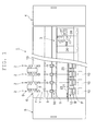
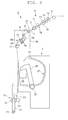
- a spinning machine 1 includes a plurality of spinning units 2, a yarn joining cart 3, a blower box 4, and a motor box 5.
- the plurality of spinning units 2 are arranged in a line.
- Each spinning unit 2 is adapted to produce a spun yarn Y and to wind the spun yarn Y into a package P.
- the yarn joining cart 3 performs a yarn joining operation in the spinning unit 2 in which the spun yarn Y is disconnected.
- the blower box 4 accommodates an air supplying source (not illustrated) or the like for generating a suction flow, whirling airflow, and the like at each section of the spinning unit 2.
- the motor box 5 accommodates a motor (not illustrated) or the like for supplying power to each section of the spinning unit 2.
- a side where the spun yarn Y is produced is referred to as upstream and a side where the spun yarn Y is wound is referred to as downstream.
- a side where the yarn path is located with respect to the yarn joining cart 3 is referred to as a front side, and a side opposite to the front side is referred to as a back side.
- a work passage (not illustrated) extending in a direction in which the plurality of spinning units 2 are arranged is provided on the front side of the spinning machine 1.
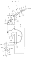
- each spinning unit 2 includes a draft device (yarn supplying device) 6, a spinning device (yarn supplying device) 7, a yarn clearer (yarn defect detection device) 8, a tension sensor (tension measuring device) 9, a yarn accumulating device 50, a waxing device 11, and a winding device 12 in this order from the upstream.
- a draft device yarn supplying device
- a spinning device yarn supplying device
- a yarn clearer yarn defect detection device
- tension sensor tension measuring device 9
- yarn accumulating device 50 e.g., the downstream side is located at a lower side
- the yarn clearer 8, the tension sensor 9, the yarn accumulating device 50, and the waxing device 11 are detachably provided with respect to the frame 13 as a yarn processing module 80.
- the draft device 6 drafts a sliver S to produce a fiber bundle F (i.e., drafts the fiber bundle F).
- the draft device 6 includes a back roller pair 14, a third roller pair 15, a middle roller pair 17 provided with apron belts 16, and a front roller pair 18.
- a bottom roller of each of the roller pairs 14, 15, 17, and 18 is driven at a different rotation speed by power from the motor box 5 or by power of an electric motor (not illustrated) provided in each spinning unit 2. Accordingly, the draft device 6 drafts the sliver S supplied from the upstream to produce the fiber bundle F, and supplies the fiber bundle F to the spinning device 7 located downstream.
- the spinning device 7 is a pneumatic spinning device adapted to produce the spun yarn Y by twisting the fiber bundle F by whirling airflow. More specifically (although not illustrated), the spinning device 7 includes a spinning chamber, a fiber guiding section, a whirling airflow generating nozzle, and a hollow guide shaft body.
- the fiber guiding section is adapted to guide the fiber bundle F supplied from the draft device 6 located upstream into the spinning chamber.
- the whirling airflow generating nozzle is arranged at a periphery of a path through which the fiber bundle F travels, and is adapted to generate the whirling airflow in the spinning chamber. This whirling airflow causes a fiber end of the fiber bundle F guided into the spinning chamber to be reversed and to whirl.
- the hollow guide shaft body is adapted to guide the spun yarn Y from the spinning chamber to outside the spinning device 7.
- the yarn clearer 8 is adapted to detect a yarn defect of the travelling spun yarn Y between the spinning device 7 and the yarn accumulating device 50, and transmit a yarn defect detection signal to a unit controller 10.
- the yarn clearer 8 detects thickness abnormality of the spun yarn Y and/or foreign substances contained in the spun yarn Y, for example, as the yarn defect.
- the tension sensor 9 is adapted to measure tension of the travelling spun yarn Y between the spinning device 7 and the yarn accumulating device 50, and transmit a tension measurement signal to the unit controller 10.
- the waxing device 11 is adapted to apply wax on the travelling spun yarn Y between the yarn accumulating device 50 and the winding device 12.
- the unit controller 10 is provided for each spinning unit 2, and is adapted to control an operation of the spinning unit 2.
- the yarn accumulating device 50 is adapted to accumulate the travelling spun yarn Y between the spinning device 7 and the winding device 12.
- the yarn accumulating device 50 has a function of stably pulling out the spun yarn Y from the spinning device 7, a function of accumulating the spun yarn Y fed from the spinning device 7 to prevent the spun yarn Y from slackening during the yarn joining operation by the yarn joining cart 3 or the like, and a function of adjusting the tension of the spun yarn Y from the winding device 12 to prevent a fluctuation in the tension of the spun yarn Y from the winding device 12 from being transmitted towards the spinning device 7.
- the winding device 12 winds the spun yarn Y into the package P to form a fully-wound package P.
- the winding device 12 includes a cradle arm 21, a winding drum 22, and a traverse device 23.
- the cradle arm 21 is swingably supported by a supporting shaft 24, and causes a surface of a rotatably supporting bobbin B or a surface of the package P (i.e., the package P formed by winding the spun yarn Y around the bobbin B) to make contact with a surface of the winding drum 22 at an appropriate pressure.
- the winding drum 22 is driven by the electric motor (not illustrated) provided in each spinning unit 2 to rotate the bobbin B or the package P making contact with the winding drum 22.
- the traverse device 23 is driven by a common shaft 25 for the plurality of spinning units 2, and traverses the spun yarn Y at a predetermined width with respect to the rotating bobbin B and/or the package P.
- the yarn joining cart 3 travels to the spinning unit 2 in which the spun yarn Y is disconnected to perform the yarn joining operation to the target spinning unit 2.
- the yarn joining cart 3 includes a splicer (yarn joining device) 26, a suction pipe 27, and a suction mouth 28.
- the suction pipe 27 is swingably supported by a supporting shaft 31, and sucks and catches the yarn end of the spun yarn Y from the spinning device 7 to guide the yarn end to the splicer 26.
- the suction mouth 28 is swingably supported by a supporting shaft 32, and sucks and catches the yarn end of the spun yarn Y from the winding device 12 to guide the yarn end to the splicer 26.
- the splicer 26 joins the guided yarn ends.
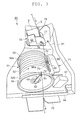
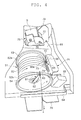
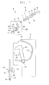
- the yarn accumulating device 50 includes a yarn accumulating roller 51, an electric motor (driving motor) 55, an accumulated-yarn-amount lower limit sensor 56, an accumulated-yarn-amount upper limit sensor 57, a yarn hooking member 61, a yarn removing member 64, a suction mechanism 65, and a restricting member 71.
- a first guiding member 78 and a yarn movement control member 75 are provided between the spinning device 7 and the yarn accumulating roller 51 in this order from the upstream.
- a second guiding member 79 is provided between the yarn accumulating roller 51 and the winding device 12.
- the yarn accumulating roller 51 is fixed to a driving shaft of the electric motor 55, and is rotated by the electric motor 55.
- the yarn accumulating roller 51 includes a yarn accumulating section 52, a basal end tapered section 53, and a distal end tapered section 54.
- the yarn accumulating section 52 is a cylindrical portion around which the spun yarn Y is wound, and is slightly tapered towards the distal end.
- the basal end tapered section 53 expands towards the upstream from a basal end portion 52a where winding of the spun yarn Y around the yarn accumulating section 52 starts.
- the distal end tapered section 54 expands towards the downstream from a distal end portion 52b of the yarn accumulating section 52.
- the basal end tapered section 53 is adapted to receive the spun yarn Y guided to the yarn accumulating roller 51 from the upstream and smoothly guide the spun yarn Y to the basal end portion 52a of the yarn accumulating section 52. Accordingly, the spun yarn Y is regularly wound around the yarn accumulating section 52 from the basal end towards the distal end.
- the distal end tapered section 54 smoothly guides the spun yarn Y towards the downstream from the yarn accumulating roller 51 while preventing occurrence of a sloughing phenomenon in which the spun yarn Y wound around the yarn accumulating section 52 slips off all at once.
- the accumulated-yarn-amount lower limit sensor 56 is adapted to detect presence or absence of the spun yarn Y on the yarn accumulating roller 51 in a non-contacting manner, and is located at the back of the yarn accumulating roller 51 and arranged to face the yarn accumulating section 52. When an accumulated amount of the spun yarn Y wound around the yarn accumulating roller 51 reaches a lower limit amount, the accumulated-yarn-amount lower limit sensor 56 transmits an accumulated-amount lower limit detection signal to the unit controller 10.
- the accumulated-yarn-amount upper limit sensor 57 is adapted to detect the presence or the absence of the spun yarn Y on the yarn accumulating roller 51 in the non-contacting manner, and is located at a side of the yarn accumulating roller 51 and arranged to face the distal end portion 52b of the yarn accumulating section 52.
- the accumulated-yarn-amount upper limit sensor 57 transmits an accumulated-amount upper limit detection signal to the unit controller 10.
- the yarn hooking member 61 is arranged on a side of the yarn accumulating roller 51 located closer to the winding device 12, and is adapted to hook the spun yarn Y and wind the spun yarn Y around the yarn accumulating roller 51.
- the yarn hooking member 61 includes a flyer shaft 62 and a flyer 63.
- the flyer shaft 62 is arranged on the distal end side of the yarn accumulating roller 51, and supported in a relatively rotatable manner about the same shaft with respect to the yarn accumulating roller 51.
- the flyer 63 is fixed to a distal end of the flyer shaft 62, and is curved onto the distal end tapered section 54 of the yarn accumulating roller 51 such as to hook the spun yarn Y.
- a magnetic force acts between the yarn accumulating roller 51 and the flyer shaft 62.
- the yarn hooking member 61 is required to generate a torque of greater than or equal to a prescribed value.
- the yarn removing member 64 is adapted to remove the spun yarn Y from the yarn hooking member 61, and is arranged in proximity to the distal end tapered section 54 of the yarn accumulating roller 51.
- the yarn removing member 64 is supported in a swingable manner between a lowered position and an elevated position.
- the lowered position is a position retreated from the yarn path.
- the elevated position is a position of removing the spun yarn Y from the yarn hooking member 61 by pushing up the spun yarn Y on the yarn path.
- the yarn removing member 64 is urged towards the lowered position by a spring (not illustrated). Therefore, the yarn removing member 64 is normally located at the lowered position, and is moved to the elevated position by a pneumatic cylinder (not illustrated) provided in the yarn joining cart 3 during the yarn joining operation or the like.
- the suction mechanism 65 causes a suction opening 66a arranged to face the basal end tapered section 53 of the yarn accumulating roller 51 to generate a suction airflow.
- the suction opening 66a is provided at one end of a pipe-like member 66.
- the other end of the pipe-like member 66 is connected to a common fiber dust collecting chamber (not illustrated) for the suction pipe 27 and the suction mouth 28 via a piping (not illustrated).
- a piping not illustrated
- the restricting member 71 is arranged at a side of the yarn accumulating roller 51 (to face the yarn accumulating section 52).
- the restricting member 71 includes a first restricting section 72, a second restricting section 73, and a third restricting section 74.
- the first restricting section 72 is located upstream of the suction opening 66a in a rotational direction of the yarn accumulating roller 51 during the winding of the spun yarn Y.
- the second restricting section 73 is located downstream of the suction opening 66a in the rotational direction.
- the first restricting section 72 and the second restricting section 73 are arranged to face the basal end portion 52a of the yarn accumulating section 52.
- the yarn end of the spun yarn Y swung around on the basal end portion 52a side of the yarn accumulating section 52 is restricted from moving towards the distal end portion 52b of the yarn accumulating section 52 prior to an orderly unwinding of the spun yarn Y from the distal end portion 52b of the yarn accumulating section 52 by the first restricting section 72 and the second restricting section 73.
- the third restricting section 74 is arranged to face the yarn accumulating section 52.
- the yarn end of the spun yarn Y swung around on the distal end portion 52b side of the yarn accumulating section 52 is restricted from moving towards the basal end portion 52a of the yarn accumulating section 52 prior to the orderly unwinding of the spun yarn Y from the basal end portion 52a of the yarn accumulating section 52 by the third restricting section 74.
- the accumulated-yarn-amount upper limit sensor 57 is attached to a lower end of the restricting member 71.
- the yarn movement control member 75 is a plate attached to the upstream of the yarn accumulating roller 51 (a lower surface of the tension sensor 9 (a downstream end surface) herein), and includes a guide-function portion 76 and a restricting-function portion 77.
- the guide-function portion 76 is adapted to guide the spun yarn Y to the basal end tapered section 53 of the yarn accumulating roller 51 while applying tension to the spun yarn Y. Furthermore, the guide-function portion 76 prevents twists of the spun yarn Y transmitted from the spinning device 7 from being propagated downstream of the guide-function portion 76.
- the restricting-function portion 77 restricts the movement of the spun yarn Y upon disconnection of the spun yarn Y at the spinning device 7 such that the yarn end of the spun yarn Y is prevented from being displaced from the yarn path of the spun yarn Y guided to the yarn accumulating device 50.
- the first guiding member 78 is a plate attached to the upstream of the yarn accumulating roller 51 (the lower surface of the tension sensor 9 (the downstream end surface) herein), and is adapted to guide the spun yarn Y from a slit formed in a housing of the tension sensor 9 to a prescribed detecting position arranged in the housing.
- the second guiding member 79 is a plate attached to the downstream of the yarn accumulating roller 51 (on a module frame 81 of the yarn processing module 80 herein).
- the second guiding member 79 is adapted to guide the spun yarn Y to a prescribed position of the waxing device 11 and to regulate the path of the spun yarn Y swung around by the rotating yarn hooking member 61 to stabilize the travelling of the spun yarn Y located downstream of the second guiding member 79.
- the electric motor 55 drives the yarn accumulating roller 51 at a substantially prescribed rotation speed. Accordingly, the yarn hooking member 61 integrally rotates with the yarn accumulating roller 51, and the flyer 63 hooks the spun yarn Y. The yarn hooking member 61 that rotates with the hooked spun yarn Y winds the spun yarn Y around the rotating yarn accumulating roller 51.
- the unit controller 10 controls the operation of the spinning unit 2 such that the accumulated amount of the spun yarn Y wound around the yarn accumulating roller 51 is greater than or equal to a lower limit amount and smaller than or equal to an upper limit amount based on an accumulated-amount lower limit detection signal transmitted from the accumulated-yarn-amount lower limit sensor 56 and an accumulated-amount upper limit detection signal transmitted from the accumulated-yarn-amount upper limit sensor 57.
- the yarn accumulating device 50 can stably (i.e., at substantially constant quality and substantially prescribed speed) pull out the spun yarn Y from the spinning device 7 by rotation of the yarn accumulating roller 51.
- the yarn hooking member 61 integrally rotates with the yarn accumulating roller 51.
- the yarn accumulating device 50 adjusts the tension of the spun yarn Y from the winding device 12 to prevent the fluctuation in the tension of the spun yarn Y from the winding device 12 from being transmitted towards the spinning device 7 as described above.
- the yarn clearer 8 detects the yarn defect during the normal operation of producing the spun yarn Y and winding the spun yarn Y into the package P
- the yarn clearer 8 transmits a yarn defect detection signal to the unit controller 10.
- the unit controller 10 Upon receiving the yarn defect detection signal, the unit controller 10 immediately stops an operation of the draft device 6, the spinning device 7, and the like. Accordingly, the twists are no longer applied to the fiber bundle F, and the spun yarn Y is disconnected at the spinning device 7.
- the unit controller 10 continues the rotation of the yarn accumulating roller 51 and the winding by the winding device 12.
- the yarn end of the disconnected spun yarn Y is wound by the yarn accumulating roller 51, and is swung around on the basal end portion 52a side of the yarn accumulating section 52.
- the yarn end is subjected to the action of the suction flow generated at the suction opening 66a while the movement towards the distal end portion 52b of the yarn accumulating section 52 is restricted by the first restricting section 72 of the restricting member 71.
- the spun yarn Y is smoothly unwound from the yarn accumulating roller 51 towards the winding device 12. While the spun yarn Y is being unwound, the fiber dusts of the upstream yarn end are removed by the suction mechanism 65 without hardly scattering.
- the unit controller 10 transmits a control signal indicating the spinning unit 2 in which the spun yarn Y is disconnected to the yarn joining cart 3.
- the yarn joining cart 3 thereby travels to front of the relevant spinning unit 2, and starts the yarn joining operation.
- the suction mouth 28 is swung to proximity of the surface of the package P and generates the suction flow, and the winding device 12 reversely rotates the package P.
- the suction mouth 28 thereby pulls out and catches the yarn end of the spun yarn Y from the surface of the package P.
- the suction mouth 28 is swung to an original position (a standby position) to guide the yarn end of the spun yarn Y from the winding device 12 to the splicer 26.
- the winding device 12 stops the rotation of the package P.
- the suction pipe 27 is swung towards the downstream of the spinning device 7 and generates the suction flow.
- the suction pipe 27 catches the yarn end of the produced spun yarn Y.
- the suction pipe 27 is swung to the original position (the standby position) to guide the yarn end of the spun yarn Y from the spinning device 7 to the splicer 26.
- the yarn hooking member 61 hooks the spun yarn Y from the spinning device 7 and winds the spun yarn Y around the integrally rotating yarn accumulating roller 51. Accordingly, even if the winding by the winding device 12 is stopped, slackening hardly occurs in the spun yarn Y fed from the spinning device 7. Thus, the yarn accumulating device 50 can accumulate the spun yarn Y fed from the spinning device 7 and prevent the spun yarn Y from slackening during the yarn joining operation by the yarn joining cart 3, and the like.
- the spun yarn Y is stably (i.e., at substantially constant quality and substantially prescribed speed) pulled out from the spinning device 7.
- the unit controller 10 moves the yarn removing member 64 from the lowered position to the elevated position, and the yarn removing member 64 removes the spun yarn Y from the yarn hooking member 61.
- the unit controller 10 moves the yarn removing member 64 from the elevated position to the lowered position. Accordingly, the spun yarn Y from the spinning device 7 is hooked to the yarn hooking member 61, and the spun yarn Y is not unwound towards the downstream from the yarn accumulating roller 51.
- the splicer 26 joins the yarn end of the spun yarn Y from the winding device 12 and the yarn end of the spun yarn Y from the spinning device 7. The unnecessary yarn end disconnected in the splicer 26 is removed by the suction pipe 27 and the suction mouth 28. After the yarn joining operation by the splicer 26 is finished, the unit controller 10 resumes the winding by the winding device 12.
- the spinning unit 2 upon an occurrence of a yarn breakage will be described.
- the spun yarn Y in the spinning unit 2, during the normal operation of producing the spun yarn Y and winding the spun yarn Y into the package P, when the spun yarn Y is disconnected at the downstream of the yarn accumulating device 50, the spun yarn Y cannot be detected by a yarn travelling sensor (not illustrated) arranged downstream of the yarn accumulating device 50.
- the unit controller 10 determines that a yarn breakage has occurred between the yarn accumulating device 50 and the winding device 12, and immediately stops the operation of the draft device 6, the spinning device 7, and the like. Accordingly, the twists are no longer applied to the fiber bundle F, and the spun yarn Y is also disconnected at the spinning device 7.
- the unit controller 10 continues the rotation of the yarn accumulating roller 51 and the winding by the winding device 12.
- the yarn end of the disconnected spun yarn Y is wound by the yarn accumulating roller 51, and is swung around on the basal end portion 52a side of the yarn accumulating section 52.
- the yarn end of the spun yarn Y that is swung around is subjected to the action of the suction flow generated at the suction opening 66a while the movement towards the distal end portion 52b of the yarn accumulating section 52 is being restricted by the first restricting section 72 of the restricting member 71.
- the fiber dusts of the upstream yarn end are removed by the suction mechanism 65 without hardly scattering.
- the unit controller 10 stops forward rotation (a normal rotational direction) of the yarn accumulating roller 51, and reversely rotates the yarn accumulating roller 51.
- the movement of the upstream yarn end of the spun yarn Y wound around the yarn accumulating roller 51 towards the distal end portion 52b of the yarn accumulating section 52 is restricted by the second restricting section 73 of the restricting member 71.
- the upstream yarn end is reliably caught at the suction opening 66a of the suction mechanism 65.
- the movement of the downstream yarn end of the spun yarn Y wound around the yarn accumulating roller 51 towards the basal end portion 52a of the yarn accumulating section 52 is restricted by the third restricting section 74 of the restricting member 71. Therefore, the spun yarn Y wound around the yarn accumulating roller 51 is smoothly unwound from the basal end portion 52a of the yarn accumulating section 52, and sucked by the suction mechanism 65.
- the unit controller 10 stops the reverse rotation of the yarn accumulating roller 51 and forwardly rotates the yarn accumulating roller 51.
- the unit controller 10 transmits the control signal indicating the spinning unit 2 in which the spun yarn Y is disconnected to the yarn joining cart 3. Accordingly, the yarn joining cart 3 travels to the front of the relevant spinning unit 2, and performs the yarn joining operation described above.
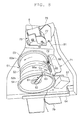
- the yarn movement control member 75 includes a fixing portion 91, a rising portion 92, and a body portion 93.
- the fixing portion 91 is fixed to a lower surface 9a of the tension sensor 9 on one side with respect to the yarn path.
- the rising portion 92 is raised from the fixing portion 91 towards the yarn accumulating roller 51.
- the body portion 93 expands towards the yarn path from the rising portion 92.
- the fixing portion 91, the rising portion 92, and the body portion 93 are integrally formed from a plate 90 made of metal.
- An upright portion 91a is arranged at a portion on the front side of the fixing portion 91.
- the upright portion 91a is formed to rise from one end side with respect to the yarn path towards the tension sensor 9.
- a guiding groove 91b opening towards the back side is formed at an end on the back side of the fixing portion 91.
- a position of the yarn movement control member 75 is determined by making the upright portion 91a to contact with a side surface 9b of the tension sensor 9 at one side with respect to the yarn path. With the position being determined in such a manner, the yarn movement control member 75 is fixed to the lower surface 9a of the tension sensor 9 with a bolt 94 passing through the guiding groove 91b.
- the portion on the back side of the body portion 93 is the guide-function portion 76 adapted to guide the spun yarn Y to the basal end tapered section 53 of the yarn accumulating roller 51 while applying tension to the spun yarn Y.
- the portion on the front side of the body portion 93 is the restricting-function portion 77 adapted to restrict the yarn end of the spun yarn Y from being displaced from the yarn path of the spun yarn Y guided by the yarn accumulating device 50 (i.e., prior to the travelling of the spun yarn Y guided to the yarn accumulating device 50 by the guide-function portion 76) upon disconnection of the spun yarn Y at the spinning device 7.
- the guide-function portion 76 makes contact with the spun yarn Y from the front side (see FIG.
- the restricting-function portion 77 is positioned further to the front with respect to the guide-function portion 76.
- the guide-function portion 76 is arranged such that the extension line of the yarn path of the spun yarn Y travelling from the spinning device 7 to the yarn movement control member 75 is located between the guide-function portion 76 and the yarn accumulating device 50.
- the restricting-function portion 77 is arranged to be located on an opposite side of the extension line of the yarn path with respect to the guide-function portion 76.
- a second cutout (the guiding section) 93a is formed on the body portion 93.
- the second cutout 93a is cut out to expand towards the front side from another end side of the body portion 93 with respect to the yarn path.
- the second cutout 93a is formed in the yarn movement control member 75 to be along a rotational direction of the yarn hooking member 61 at a start of winding of the spun yarn Y around the yarn accumulating roller 51.
- the second cutout 93a guides the spun yarn Y towards the guide-function portion 76 from a side (the front side herein) where the restricting-function portion 77 is located with respect to the extension line of the yarn path of the spun yarn Y travelling from the spinning device 7 to the yarn movement control member 75.
- the body portion 93 includes a projection (a restricting section) 93b projecting out from the other end side with respect to the yarn path towards the back side.
- a ceramic plate 95 having a through-hole 95a is attached to an upper surface of the body portion 93 (i.e., a surface facing the lower surface 9a of the tension sensor 9).
- a position of the ceramic plate 95 is determined by fitting a protrusion 93c provided on the upper surface of the body portion 93 into the through-hole 95a. With the position determined in such a manner, the ceramic plate 95 is fixed to the upper surface of the body portion 93 with an adhesive.
- the spun yarn Y is wound around the yarn accumulating roller 51, the spun yarn Y makes contact with a portion 95b of the ceramic plate 95.
- the portion 95b of the ceramic plate 85 has a shape corresponding to a corner formed by the guide-function portion 76 and the projection 93b. That is, the portion 95b of the guide-function portion 76 where the travelling spun yarn Y makes contact is made of ceramics.
- the first guiding member 78 is fixed to the lower surface 9a of the tension sensor 9 at the opposite side of the yarn movement control member 75 with respect to the yarn path.
- a protrusion 78a is provided on a rear portion of the upper surface of the first guiding member 78.
- a position of the first guiding member 78 is determined by making the protrusion 78a to contact with a back surface 9c of the tension sensor 9. With the position determined in such a manner, the first guiding member 78 is fixed to the lower surface 9a of the tension sensor 9 with a bolt 96.
- a first cutout 78b is formed on the first guiding member 78. The first cutout 78b is cut out to expand towards the front side from the end of the first guiding member 78 located at the yarn path side.
- the first cutout 78b functions as a guiding section adapted to guide the spun yarn Y at a position between the tension sensor 9 and the yarn movement control member 75.
- the first cutout 78b guides the spun yarn Y to the prescribed detecting position of the tension sensor 9 arranged in the housing from the slit formed in the housing of the tension sensor 9.
- the spun yarn Y applied with tension is guided to the yarn accumulating roller 51 of the yarn accumulating device 50 by the guide-function portion 76 of the yarn movement control member 75.
- the spun yarn Y can be stably wound around the yarn accumulating roller 51 by the cooperative operation of the guide-function portion 76 of the yarn movement control member 75 and the yarn hooking member 61.
- the yarn end of the spun yarn Y is restricted from being displaced from the yarn path of the spun yarn Y guided to the yarn accumulating device 50 by the restricting-function portion 77 of the yarn movement control member 75.
- the yarn end of the spun yarn Y can be prevented from being entangled with the spun yarn Y wound around the yarn accumulating roller 51, and the yarn end of the spun yarn Y disconnected under a high tension state can be prevented from moving beyond the yarn accumulating roller 51 and being entangled around the yarn hooking member 61.
- the spun yarn Y can be appropriately guided to the yarn accumulating roller 51, and the movement of the yarn end of the spun yarn Y upon disconnection of the spun yarn Y can be controlled.
- the guide-function portion 76 is arranged such that the extension line of the yarn path of the spun yarn Y travelling from the spinning device 7 to the yarn movement control member 75 is located between the guide-function portion 76 and the yarn accumulating device 50.
- the restricting-function portion 77 is arranged so as to be located on the opposite side of the extension line of the yarn path with respect to the guide-function portion 76.
- the yarn movement control member 75 includes the second cutout 93a adapted to guide, at the start of winding of the spun yarn Y around the yarn accumulating roller 51, the spun yarn Y to the guide-function portion 76 from the side where the restricting-function portion 77 is located with respect to the extension line of the yarn path of the spun yarn Y travelling from the spinning device 7 to the yarn movement control member 75. Accordingly, the spun yarn Y can be reliably guided to the guide-function portion 76.
- the second cutout 93a is formed in the yarn movement control member 75 to be along the rotational direction of the yarn hooking member 61 at the start of winding of the spun yarn Y around the yarn accumulating roller 51.
- the spun yarn Y can be smoothly guided to the guide-function portion 76 by the cooperative operation of the second cutout 93a and the yarn hooking member 61.
- the yarn movement control member 75 includes the projection 93b for restricting the spun yarn Y from moving in the rotational direction of the yarn accumulating roller 51 from the guide-function portion 76 during the winding of the spun yarn Y around the yarn accumulating roller 51. Accordingly, the application of tension to the spun yarn Y by the guide-function portion 76 and the guiding of the spun yarn Y to the yarn accumulating device 50 by the guide-function portion 76 can be stabilized.
- the portion of the guide-function portion 76 where the travelling spun yarn Y makes contact is made of ceramics. Since ceramics is a material having low friction resistance with the spun yarn Y and low abrasion, the application of tension to the spun yarn Y by the guide-function portion 76 and the guiding of the spun yarn Y to the yarn accumulating device 50 by the guide-function portion 76 can be further stabilized.
- the spinning unit 2 includes the tension sensor 9 adapted to measure the tension of the spun yarn Y between the spinning device 7 and the yarn movement control member 75.
- the tension sensor 9 adapted to measure the tension of the spun yarn Y between the spinning device 7 and the yarn movement control member 75.
- the spinning unit 2 includes the first guiding member 78 adapted to guide the spun yarn Y between the tension sensor 9 and the yarn movement control member 75 such that the spun yarn Y is guided to a prescribed detecting position of the tension sensor 9. Accordingly, the spun yarn Y can be reliably guided to the tension sensor 9.
- the yarn supplying device adapted to supply the spun yarn Y is configured by the draft device 6 and the spinning device 7.
- the spinning device 7 is a pneumatic spinning device adapted to produce the spun yarn Y by twisting the fiber bundle F by the whirling airflow. Accordingly, a high quality spun yarn Y can be efficiently supplied.
- the spinning machine 1 includes a plurality of spinning units 2, wherein each spinning unit 2 is adapted to appropriately guide the spun yarn Y to the yarn accumulating roller 51 and control the movement of the yarn end of the spun yarn Y upon disconnection of the spun yarn Y. Therefore, the spinning machine 1 can efficiently produce a high quality package P.
- the present invention is not limited to the embodiment described above.
- the yarn supplying device adapted to supply the spun yarn is configured by the draft device 6 and the spinning device 7.
- other yarn supplying devices for example, a yarn supplying device configured to supply a spun yarn from a bobbin wound with the spun yarn, may be applied to the spinning machine and the spinning unit of the present invention.
- the spinning device may further include a needle held by the fiber guiding section and arranged to protrude into the spinning chamber to prevent the twists of the fiber bundle from being propagated towards the upstream of the spinning device.
- the spinning device may prevent the twists of the fiber bundle from being propagated towards the upstream of the spinning device by a downstream end of the fiber guiding section.
- the spinning device may include a pair of air-jet nozzles adapted to apply twists in opposite directions from each other.
- the yarn accumulating device 50 has a function of pulling out the spun yarn Y from the spinning device 7.
- the spun yarn may be pulled out with a delivery roller and a nip roller from the yarn supplying device adapted to supply the spun yarn.
- the disconnection of the spun yarn Y when the yarn defect is detected is carried out by stopping the whirling airflow in the spinning device 7.
- the disconnection of the spun yarn when the yarn defect is detected may be carried out by a cutter.
- each device is arranged such that the spun yarn Y supplied on the upper side is wound on the lower side.
- each device may be arranged such that the spun yarn supplied on the lower side is wound on the upper side.
- a bottom roller of the draft device 6 and a traverse mechanism of the traverse device 23 are driven by the power from the motor box 5 (i.e., commonly driven for the plurality of spinning units 2).
- each section of the spinning unit e.g., the draft device, the spinning device, the winding device, or the like
- the tension sensor 9 may be arranged upstream of the yarn clearer 8.
- the unit controller 10 may be arranged, not for each spinning unit 2, but for each group of the plurality of spinning units 2.
- the waxing device 11, the tension sensor 9, and the yarn clearer 8 may not be arranged in the spinning unit 2.
- the winding device 12 may be driven by a common driving source for the plurality of spinning units 2.
- the cradle arm 21 is moved by an air cylinder (not illustrated) such that the package P moves away from the winding drum 22, and the package P is reversely rotated by a reverse rotation roller (not illustrated) arranged in the yarn joining cart 3.
- the yarn clearer 8 the tension sensor 9, the yarn accumulating device 50, and the waxing device 11 may be directly or indirectly supported by the frame 13 individually.
- the spinning machine 1 and the spinning unit 2 include the tension sensor 9 as the spinning sensor for detecting the travelling state of the spun yarn between the yarn supplying device and the yarn movement control member.
- the spinning machine and the spinning unit of the present invention may include other spinning sensors.
Landscapes
- Engineering & Computer Science (AREA)
- Textile Engineering (AREA)
- Mechanical Engineering (AREA)
- Spinning Or Twisting Of Yarns (AREA)
Applications Claiming Priority (1)
| Application Number | Priority Date | Filing Date | Title |
|---|---|---|---|
| JP2011205331A JP2013067874A (ja) | 2011-09-20 | 2011-09-20 | 紡績ユニット及び紡績装置 |
Publications (3)
| Publication Number | Publication Date |
|---|---|
| EP2573224A2 true EP2573224A2 (de) | 2013-03-27 |
| EP2573224A3 EP2573224A3 (de) | 2015-06-17 |
| EP2573224B1 EP2573224B1 (de) | 2018-09-05 |
Family
ID=46384214
Family Applications (1)
| Application Number | Title | Priority Date | Filing Date |
|---|---|---|---|
| EP12173362.0A Not-in-force EP2573224B1 (de) | 2011-09-20 | 2012-06-25 | Spinneinheit und Spinnvorrichtung |
Country Status (3)
| Country | Link |
|---|---|
| EP (1) | EP2573224B1 (de) |
| JP (1) | JP2013067874A (de) |
| CN (1) | CN103014939B (de) |
Cited By (1)
| Publication number | Priority date | Publication date | Assignee | Title |
|---|---|---|---|---|
| EP2573018A3 (de) * | 2011-09-20 | 2016-04-27 | Murata Machinery, Ltd. | Spinneinheit und Spinnmaschine |
Families Citing this family (6)
| Publication number | Priority date | Publication date | Assignee | Title |
|---|---|---|---|---|
| JP2015161032A (ja) * | 2014-02-25 | 2015-09-07 | 村田機械株式会社 | 糸貯留装置、これを備えた糸巻取ユニット、及びこれを備えた糸巻取機 |
| JP2016016969A (ja) * | 2014-07-10 | 2016-02-01 | 村田機械株式会社 | 糸貯留装置、糸巻取ユニット及び糸巻取機 |
| JP2017065898A (ja) * | 2015-09-30 | 2017-04-06 | 村田機械株式会社 | 糸掛け部材、糸貯留装置、及び糸巻取機 |
| JP2018080406A (ja) * | 2016-11-14 | 2018-05-24 | 村田機械株式会社 | 紡績ユニット及び紡績機 |
| CN106948091B (zh) * | 2017-04-19 | 2023-06-20 | 广东必得福医卫科技股份有限公司 | 一种单向拉伸弹性无纺布生产设备 |
| CN109868532B (zh) * | 2019-03-03 | 2021-07-23 | 常山乔杉纺织有限公司 | 一种纺织机用能够适应不同纱线的供纱装置及调节方法 |
Citations (2)
| Publication number | Priority date | Publication date | Assignee | Title |
|---|---|---|---|---|
| JP2010174421A (ja) | 2009-01-30 | 2010-08-12 | Murata Machinery Ltd | 紡績機 |
| JP2011037572A (ja) | 2009-08-10 | 2011-02-24 | Murata Machinery Ltd | 紡績機 |
Family Cites Families (4)
| Publication number | Priority date | Publication date | Assignee | Title |
|---|---|---|---|---|
| JP2001159039A (ja) * | 1999-11-25 | 2001-06-12 | Murata Mach Ltd | 糸継ぎ装置 |
| JP4048902B2 (ja) * | 2002-10-07 | 2008-02-20 | 村田機械株式会社 | 紡績機の糸弛み取り装置 |
| JP3700706B2 (ja) * | 2003-03-13 | 2005-09-28 | 村田機械株式会社 | 紡績機 |
| JP2010077576A (ja) * | 2008-09-29 | 2010-04-08 | Murata Machinery Ltd | 紡績機 |
-
2011
- 2011-09-20 JP JP2011205331A patent/JP2013067874A/ja not_active Withdrawn
-
2012
- 2012-06-25 EP EP12173362.0A patent/EP2573224B1/de not_active Not-in-force
- 2012-07-12 CN CN201210244711.4A patent/CN103014939B/zh active Active
Patent Citations (2)
| Publication number | Priority date | Publication date | Assignee | Title |
|---|---|---|---|---|
| JP2010174421A (ja) | 2009-01-30 | 2010-08-12 | Murata Machinery Ltd | 紡績機 |
| JP2011037572A (ja) | 2009-08-10 | 2011-02-24 | Murata Machinery Ltd | 紡績機 |
Cited By (1)
| Publication number | Priority date | Publication date | Assignee | Title |
|---|---|---|---|---|
| EP2573018A3 (de) * | 2011-09-20 | 2016-04-27 | Murata Machinery, Ltd. | Spinneinheit und Spinnmaschine |
Also Published As
| Publication number | Publication date |
|---|---|
| CN103014939B (zh) | 2017-10-13 |
| CN103014939A (zh) | 2013-04-03 |
| JP2013067874A (ja) | 2013-04-18 |
| EP2573224B1 (de) | 2018-09-05 |
| EP2573224A3 (de) | 2015-06-17 |
Similar Documents
| Publication | Publication Date | Title |
|---|---|---|
| EP2573224B1 (de) | Spinneinheit und Spinnvorrichtung | |
| EP2169096B1 (de) | Spinnmaschine | |
| EP2298971B1 (de) | Spinnmaschine mit Garnspeicher-Rolle | |
| EP2727870B1 (de) | Garnwickelmaschine und Garnwickelverfahren | |
| EP2284300B1 (de) | Spinnmaschine und Garnentfernungsverfahren zum Entfernen von verbleibendem Garn auf der Garnzusammentragungsrolle | |
| EP2216432B2 (de) | Garnverarbeitungsverfahren und Spinnmaschine | |
| EP2302115A1 (de) | Spinnmaschine | |
| EP2573217B1 (de) | Spinneinheit, Spinnmaschine und Garnverarbeitungsverfahren | |
| EP3072840B1 (de) | Garnwickelmaschine und garnwickelverfahren | |
| CN106567170B (zh) | 纺织机以及控制装置 | |
| EP2189557A1 (de) | Vorrichtung zur Beseitigung von Fadenlockerungen und damit ausgestattete Spinnmaschine | |
| EP2966200B1 (de) | Spinnmaschine und spinnverfahren | |
| EP2977493B1 (de) | Spinnmaschine und spinnverfahren | |
| EP2573225B1 (de) | Spinneinheit und Spinnmaschine | |
| EP2573019B1 (de) | Spinneinheit mit einer Garnspeichervorrichtung, und Spinnmaschine | |
| EP2862826B1 (de) | Garnwickelmaschine | |
| JP2013067872A (ja) | 紡績ユニット及び紡績機 | |
| JP2014009409A (ja) | 糸貯留装置、紡績ユニット、および紡績機 | |
| JP2010076889A (ja) | 糸弛み取り装置及びこれを備える繊維機械 | |
| JP2014009405A (ja) | 紡績機 | |
| JP2013057152A (ja) | 糸巻取機 | |
| CN113774526A (zh) | 气流纺纱机 | |
| JP2009046779A (ja) | 粗糸ボビン保持装置 | |
| JP2004339612A (ja) | 紡績機 |
Legal Events
| Date | Code | Title | Description |
|---|---|---|---|
| PUAI | Public reference made under article 153(3) epc to a published international application that has entered the european phase |
Free format text: ORIGINAL CODE: 0009012 |
|
| AK | Designated contracting states |
Kind code of ref document: A2 Designated state(s): AL AT BE BG CH CY CZ DE DK EE ES FI FR GB GR HR HU IE IS IT LI LT LU LV MC MK MT NL NO PL PT RO RS SE SI SK SM TR |
|
| AX | Request for extension of the european patent |
Extension state: BA ME |
|
| PUAL | Search report despatched |
Free format text: ORIGINAL CODE: 0009013 |
|
| AK | Designated contracting states |
Kind code of ref document: A3 Designated state(s): AL AT BE BG CH CY CZ DE DK EE ES FI FR GB GR HR HU IE IS IT LI LT LU LV MC MK MT NL NO PL PT RO RS SE SI SK SM TR |
|
| AX | Request for extension of the european patent |
Extension state: BA ME |
|
| RIC1 | Information provided on ipc code assigned before grant |
Ipc: B65H 51/22 20060101AFI20150513BHEP Ipc: D01H 13/04 20060101ALI20150513BHEP |
|
| 17P | Request for examination filed |
Effective date: 20151119 |
|
| RBV | Designated contracting states (corrected) |
Designated state(s): AL AT BE BG CH CY CZ DE DK EE ES FI FR GB GR HR HU IE IS IT LI LT LU LV MC MK MT NL NO PL PT RO RS SE SI SK SM TR |
|
| STAA | Information on the status of an ep patent application or granted ep patent |
Free format text: STATUS: EXAMINATION IS IN PROGRESS |
|
| 17Q | First examination report despatched |
Effective date: 20170323 |
|
| REG | Reference to a national code |
Ref country code: DE Ref legal event code: R079 Ref document number: 602012050568 Country of ref document: DE Free format text: PREVIOUS MAIN CLASS: D01H0004480000 Ipc: B65H0057000000 |
|
| GRAP | Despatch of communication of intention to grant a patent |
Free format text: ORIGINAL CODE: EPIDOSNIGR1 |
|
| STAA | Information on the status of an ep patent application or granted ep patent |
Free format text: STATUS: GRANT OF PATENT IS INTENDED |
|
| RIC1 | Information provided on ipc code assigned before grant |
Ipc: B65H 57/00 20060101AFI20180223BHEP Ipc: B65H 51/22 20060101ALI20180223BHEP Ipc: D01H 13/04 20060101ALI20180223BHEP |
|
| INTG | Intention to grant announced |
Effective date: 20180322 |
|
| GRAS | Grant fee paid |
Free format text: ORIGINAL CODE: EPIDOSNIGR3 |
|
| GRAA | (expected) grant |
Free format text: ORIGINAL CODE: 0009210 |
|
| STAA | Information on the status of an ep patent application or granted ep patent |
Free format text: STATUS: THE PATENT HAS BEEN GRANTED |
|
| AK | Designated contracting states |
Kind code of ref document: B1 Designated state(s): AL AT BE BG CH CY CZ DE DK EE ES FI FR GB GR HR HU IE IS IT LI LT LU LV MC MK MT NL NO PL PT RO RS SE SI SK SM TR |
|
| REG | Reference to a national code |
Ref country code: GB Ref legal event code: FG4D |
|
| REG | Reference to a national code |
Ref country code: CH Ref legal event code: EP |
|
| REG | Reference to a national code |
Ref country code: AT Ref legal event code: REF Ref document number: 1037547 Country of ref document: AT Kind code of ref document: T Effective date: 20180915 |
|
| REG | Reference to a national code |
Ref country code: IE Ref legal event code: FG4D |
|
| REG | Reference to a national code |
Ref country code: DE Ref legal event code: R096 Ref document number: 602012050568 Country of ref document: DE |
|
| REG | Reference to a national code |
Ref country code: CH Ref legal event code: NV Representative=s name: BOVARD AG PATENT- UND MARKENANWAELTE, CH |
|
| REG | Reference to a national code |
Ref country code: NL Ref legal event code: MP Effective date: 20180905 |
|
| REG | Reference to a national code |
Ref country code: LT Ref legal event code: MG4D |
|
| PG25 | Lapsed in a contracting state [announced via postgrant information from national office to epo] |
Ref country code: FI Free format text: LAPSE BECAUSE OF FAILURE TO SUBMIT A TRANSLATION OF THE DESCRIPTION OR TO PAY THE FEE WITHIN THE PRESCRIBED TIME-LIMIT Effective date: 20180905 Ref country code: GR Free format text: LAPSE BECAUSE OF FAILURE TO SUBMIT A TRANSLATION OF THE DESCRIPTION OR TO PAY THE FEE WITHIN THE PRESCRIBED TIME-LIMIT Effective date: 20181206 Ref country code: RS Free format text: LAPSE BECAUSE OF FAILURE TO SUBMIT A TRANSLATION OF THE DESCRIPTION OR TO PAY THE FEE WITHIN THE PRESCRIBED TIME-LIMIT Effective date: 20180905 Ref country code: NO Free format text: LAPSE BECAUSE OF FAILURE TO SUBMIT A TRANSLATION OF THE DESCRIPTION OR TO PAY THE FEE WITHIN THE PRESCRIBED TIME-LIMIT Effective date: 20181205 Ref country code: BG Free format text: LAPSE BECAUSE OF FAILURE TO SUBMIT A TRANSLATION OF THE DESCRIPTION OR TO PAY THE FEE WITHIN THE PRESCRIBED TIME-LIMIT Effective date: 20181205 Ref country code: SE Free format text: LAPSE BECAUSE OF FAILURE TO SUBMIT A TRANSLATION OF THE DESCRIPTION OR TO PAY THE FEE WITHIN THE PRESCRIBED TIME-LIMIT Effective date: 20180905 Ref country code: LT Free format text: LAPSE BECAUSE OF FAILURE TO SUBMIT A TRANSLATION OF THE DESCRIPTION OR TO PAY THE FEE WITHIN THE PRESCRIBED TIME-LIMIT Effective date: 20180905 |
|
| REG | Reference to a national code |
Ref country code: AT Ref legal event code: MK05 Ref document number: 1037547 Country of ref document: AT Kind code of ref document: T Effective date: 20180905 |
|
| PG25 | Lapsed in a contracting state [announced via postgrant information from national office to epo] |
Ref country code: HR Free format text: LAPSE BECAUSE OF FAILURE TO SUBMIT A TRANSLATION OF THE DESCRIPTION OR TO PAY THE FEE WITHIN THE PRESCRIBED TIME-LIMIT Effective date: 20180905 Ref country code: LV Free format text: LAPSE BECAUSE OF FAILURE TO SUBMIT A TRANSLATION OF THE DESCRIPTION OR TO PAY THE FEE WITHIN THE PRESCRIBED TIME-LIMIT Effective date: 20180905 Ref country code: AL Free format text: LAPSE BECAUSE OF FAILURE TO SUBMIT A TRANSLATION OF THE DESCRIPTION OR TO PAY THE FEE WITHIN THE PRESCRIBED TIME-LIMIT Effective date: 20180905 |
|
| PG25 | Lapsed in a contracting state [announced via postgrant information from national office to epo] |
Ref country code: ES Free format text: LAPSE BECAUSE OF FAILURE TO SUBMIT A TRANSLATION OF THE DESCRIPTION OR TO PAY THE FEE WITHIN THE PRESCRIBED TIME-LIMIT Effective date: 20180905 Ref country code: NL Free format text: LAPSE BECAUSE OF FAILURE TO SUBMIT A TRANSLATION OF THE DESCRIPTION OR TO PAY THE FEE WITHIN THE PRESCRIBED TIME-LIMIT Effective date: 20180905 Ref country code: IS Free format text: LAPSE BECAUSE OF FAILURE TO SUBMIT A TRANSLATION OF THE DESCRIPTION OR TO PAY THE FEE WITHIN THE PRESCRIBED TIME-LIMIT Effective date: 20190105 Ref country code: PL Free format text: LAPSE BECAUSE OF FAILURE TO SUBMIT A TRANSLATION OF THE DESCRIPTION OR TO PAY THE FEE WITHIN THE PRESCRIBED TIME-LIMIT Effective date: 20180905 Ref country code: RO Free format text: LAPSE BECAUSE OF FAILURE TO SUBMIT A TRANSLATION OF THE DESCRIPTION OR TO PAY THE FEE WITHIN THE PRESCRIBED TIME-LIMIT Effective date: 20180905 Ref country code: AT Free format text: LAPSE BECAUSE OF FAILURE TO SUBMIT A TRANSLATION OF THE DESCRIPTION OR TO PAY THE FEE WITHIN THE PRESCRIBED TIME-LIMIT Effective date: 20180905 Ref country code: IT Free format text: LAPSE BECAUSE OF FAILURE TO SUBMIT A TRANSLATION OF THE DESCRIPTION OR TO PAY THE FEE WITHIN THE PRESCRIBED TIME-LIMIT Effective date: 20180905 Ref country code: EE Free format text: LAPSE BECAUSE OF FAILURE TO SUBMIT A TRANSLATION OF THE DESCRIPTION OR TO PAY THE FEE WITHIN THE PRESCRIBED TIME-LIMIT Effective date: 20180905 |
|
| PG25 | Lapsed in a contracting state [announced via postgrant information from national office to epo] |
Ref country code: SM Free format text: LAPSE BECAUSE OF FAILURE TO SUBMIT A TRANSLATION OF THE DESCRIPTION OR TO PAY THE FEE WITHIN THE PRESCRIBED TIME-LIMIT Effective date: 20180905 Ref country code: SK Free format text: LAPSE BECAUSE OF FAILURE TO SUBMIT A TRANSLATION OF THE DESCRIPTION OR TO PAY THE FEE WITHIN THE PRESCRIBED TIME-LIMIT Effective date: 20180905 Ref country code: PT Free format text: LAPSE BECAUSE OF FAILURE TO SUBMIT A TRANSLATION OF THE DESCRIPTION OR TO PAY THE FEE WITHIN THE PRESCRIBED TIME-LIMIT Effective date: 20190105 |
|
| REG | Reference to a national code |
Ref country code: DE Ref legal event code: R097 Ref document number: 602012050568 Country of ref document: DE |
|
| PLBE | No opposition filed within time limit |
Free format text: ORIGINAL CODE: 0009261 |
|
| STAA | Information on the status of an ep patent application or granted ep patent |
Free format text: STATUS: NO OPPOSITION FILED WITHIN TIME LIMIT |
|
| PG25 | Lapsed in a contracting state [announced via postgrant information from national office to epo] |
Ref country code: DK Free format text: LAPSE BECAUSE OF FAILURE TO SUBMIT A TRANSLATION OF THE DESCRIPTION OR TO PAY THE FEE WITHIN THE PRESCRIBED TIME-LIMIT Effective date: 20180905 |
|
| PGFP | Annual fee paid to national office [announced via postgrant information from national office to epo] |
Ref country code: DE Payment date: 20190619 Year of fee payment: 8 Ref country code: CZ Payment date: 20190527 Year of fee payment: 8 |
|
| 26N | No opposition filed |
Effective date: 20190606 |
|
| PG25 | Lapsed in a contracting state [announced via postgrant information from national office to epo] |
Ref country code: SI Free format text: LAPSE BECAUSE OF FAILURE TO SUBMIT A TRANSLATION OF THE DESCRIPTION OR TO PAY THE FEE WITHIN THE PRESCRIBED TIME-LIMIT Effective date: 20180905 |
|
| PGFP | Annual fee paid to national office [announced via postgrant information from national office to epo] |
Ref country code: CH Payment date: 20190619 Year of fee payment: 8 |
|
| PG25 | Lapsed in a contracting state [announced via postgrant information from national office to epo] |
Ref country code: MC Free format text: LAPSE BECAUSE OF FAILURE TO SUBMIT A TRANSLATION OF THE DESCRIPTION OR TO PAY THE FEE WITHIN THE PRESCRIBED TIME-LIMIT Effective date: 20180905 |
|
| GBPC | Gb: european patent ceased through non-payment of renewal fee |
Effective date: 20190625 |
|
| REG | Reference to a national code |
Ref country code: BE Ref legal event code: MM Effective date: 20190630 |
|
| PG25 | Lapsed in a contracting state [announced via postgrant information from national office to epo] |
Ref country code: TR Free format text: LAPSE BECAUSE OF FAILURE TO SUBMIT A TRANSLATION OF THE DESCRIPTION OR TO PAY THE FEE WITHIN THE PRESCRIBED TIME-LIMIT Effective date: 20180905 |
|
| PG25 | Lapsed in a contracting state [announced via postgrant information from national office to epo] |
Ref country code: GB Free format text: LAPSE BECAUSE OF NON-PAYMENT OF DUE FEES Effective date: 20190625 Ref country code: IE Free format text: LAPSE BECAUSE OF NON-PAYMENT OF DUE FEES Effective date: 20190625 |
|
| PG25 | Lapsed in a contracting state [announced via postgrant information from national office to epo] |
Ref country code: BE Free format text: LAPSE BECAUSE OF NON-PAYMENT OF DUE FEES Effective date: 20190630 Ref country code: LU Free format text: LAPSE BECAUSE OF NON-PAYMENT OF DUE FEES Effective date: 20190625 |
|
| PG25 | Lapsed in a contracting state [announced via postgrant information from national office to epo] |
Ref country code: FR Free format text: LAPSE BECAUSE OF NON-PAYMENT OF DUE FEES Effective date: 20190630 |
|
| REG | Reference to a national code |
Ref country code: DE Ref legal event code: R119 Ref document number: 602012050568 Country of ref document: DE |
|
| PG25 | Lapsed in a contracting state [announced via postgrant information from national office to epo] |
Ref country code: CZ Free format text: LAPSE BECAUSE OF NON-PAYMENT OF DUE FEES Effective date: 20200625 |
|
| REG | Reference to a national code |
Ref country code: CH Ref legal event code: PL |
|
| PG25 | Lapsed in a contracting state [announced via postgrant information from national office to epo] |
Ref country code: CH Free format text: LAPSE BECAUSE OF NON-PAYMENT OF DUE FEES Effective date: 20200630 Ref country code: LI Free format text: LAPSE BECAUSE OF NON-PAYMENT OF DUE FEES Effective date: 20200630 |
|
| PG25 | Lapsed in a contracting state [announced via postgrant information from national office to epo] |
Ref country code: CY Free format text: LAPSE BECAUSE OF FAILURE TO SUBMIT A TRANSLATION OF THE DESCRIPTION OR TO PAY THE FEE WITHIN THE PRESCRIBED TIME-LIMIT Effective date: 20180905 Ref country code: DE Free format text: LAPSE BECAUSE OF NON-PAYMENT OF DUE FEES Effective date: 20210101 |
|
| PG25 | Lapsed in a contracting state [announced via postgrant information from national office to epo] |
Ref country code: HU Free format text: LAPSE BECAUSE OF FAILURE TO SUBMIT A TRANSLATION OF THE DESCRIPTION OR TO PAY THE FEE WITHIN THE PRESCRIBED TIME-LIMIT; INVALID AB INITIO Effective date: 20120625 Ref country code: MT Free format text: LAPSE BECAUSE OF FAILURE TO SUBMIT A TRANSLATION OF THE DESCRIPTION OR TO PAY THE FEE WITHIN THE PRESCRIBED TIME-LIMIT Effective date: 20180905 |
|
| PG25 | Lapsed in a contracting state [announced via postgrant information from national office to epo] |
Ref country code: MK Free format text: LAPSE BECAUSE OF FAILURE TO SUBMIT A TRANSLATION OF THE DESCRIPTION OR TO PAY THE FEE WITHIN THE PRESCRIBED TIME-LIMIT Effective date: 20180905 |