EP2573030A2 - Yarn winding machine - Google Patents
Yarn winding machine Download PDFInfo
- Publication number
- EP2573030A2 EP2573030A2 EP12175315A EP12175315A EP2573030A2 EP 2573030 A2 EP2573030 A2 EP 2573030A2 EP 12175315 A EP12175315 A EP 12175315A EP 12175315 A EP12175315 A EP 12175315A EP 2573030 A2 EP2573030 A2 EP 2573030A2
- Authority
- EP
- European Patent Office
- Prior art keywords
- yarn
- winding
- joining device
- section
- yarn joining
- Prior art date
- Legal status (The legal status is an assumption and is not a legal conclusion. Google has not performed a legal analysis and makes no representation as to the accuracy of the status listed.)
- Granted
Links
Images


Classifications
-
- B—PERFORMING OPERATIONS; TRANSPORTING
- B65—CONVEYING; PACKING; STORING; HANDLING THIN OR FILAMENTARY MATERIAL
- B65H—HANDLING THIN OR FILAMENTARY MATERIAL, e.g. SHEETS, WEBS, CABLES
- B65H69/00—Methods of, or devices for, interconnecting successive lengths of material; Knot-tying devices ;Control of the correct working of the interconnecting device
- B65H69/06—Methods of, or devices for, interconnecting successive lengths of material; Knot-tying devices ;Control of the correct working of the interconnecting device by splicing
- B65H69/061—Methods of, or devices for, interconnecting successive lengths of material; Knot-tying devices ;Control of the correct working of the interconnecting device by splicing using pneumatic means
-
- B—PERFORMING OPERATIONS; TRANSPORTING
- B65—CONVEYING; PACKING; STORING; HANDLING THIN OR FILAMENTARY MATERIAL
- B65H—HANDLING THIN OR FILAMENTARY MATERIAL, e.g. SHEETS, WEBS, CABLES
- B65H54/00—Winding, coiling, or depositing filamentary material
- B65H54/02—Winding and traversing material on to reels, bobbins, tubes, or like package cores or formers
- B65H54/22—Automatic winding machines, i.e. machines with servicing units for automatically performing end-finding, interconnecting of successive lengths of material, controlling and fault-detecting of the running material and replacing or removing of full or empty cores
- B65H54/26—Automatic winding machines, i.e. machines with servicing units for automatically performing end-finding, interconnecting of successive lengths of material, controlling and fault-detecting of the running material and replacing or removing of full or empty cores having one or more servicing units moving along a plurality of fixed winding units
-
- B—PERFORMING OPERATIONS; TRANSPORTING
- B65—CONVEYING; PACKING; STORING; HANDLING THIN OR FILAMENTARY MATERIAL
- B65H—HANDLING THIN OR FILAMENTARY MATERIAL, e.g. SHEETS, WEBS, CABLES
- B65H69/00—Methods of, or devices for, interconnecting successive lengths of material; Knot-tying devices ;Control of the correct working of the interconnecting device
- B65H69/04—Methods of, or devices for, interconnecting successive lengths of material; Knot-tying devices ;Control of the correct working of the interconnecting device by knotting
-
- B—PERFORMING OPERATIONS; TRANSPORTING
- B65—CONVEYING; PACKING; STORING; HANDLING THIN OR FILAMENTARY MATERIAL
- B65H—HANDLING THIN OR FILAMENTARY MATERIAL, e.g. SHEETS, WEBS, CABLES
- B65H2701/00—Handled material; Storage means
- B65H2701/30—Handled filamentary material
- B65H2701/31—Textiles threads or artificial strands of filaments
Definitions
- the present invention relates to a yarn joining device arranged in a yarn winding machine.
- a yarn winding machine adapted to wind a yarn around a bobbin to form a package.
- This type of yarn winding machine includes, for example, a spinning machine disclosed in Japanese Unexamined Patent Publication No. 2010-77576 (Patent Document 1).
- the spinning machine includes a spinning device adapted to produce a spun yarn by applying a twist to a fiber bundle, and a winding device adapted to wind the spun yarn produced by the spinning device around the bobbin to form a package.
- the spinning machine of Patent Document 1 includes a yarn joining cart adapted to connect (join) a yarn from the spinning device and a yarn from the package when the spun yarn between the spinning device and the package is disconnected.
- the yarn joining cart includes a yarn joining device adapted to connect the yarn from the spinning device and the yarn from the package.
- the yarn joining cart includes a suction pipe adapted to catch the yarn from the spinning device and guide the yarn to the yarn joining device, and a suction mouth adapted to catch the yarn from the package and guide the yarn to the yarn joining device.
- the above yarn joining device is arranged at a position deviated from a yarn path (travelling path of the yarn) during a normal winding so as not to interfere with the yarn being wound into the package.
- the yarn joining device is arranged at a receded position on a rear side of the spinning machine (right side of FIG. 2 ) than the yarn path during the normal winding.
- the yarn path during the yarn joining operation is bent more than the yarn path during the normal winding. Since the yarn path is bent, the spun yarn between the spinning device and the package becomes longer during the yarn joining operation than during the normal winding. When the winding by the winding device is resumed after the yarn joining operation is finished, the lengthened spun yarn slackens. As a result, the yarn may be wound into a package in a slackened state or in a kinked state.
- the spinning machine described in Patent Document 1 has a rotating slack eliminating roller arranged between the spinning device and the winding device. If the yarn slackens when the winding is resumed, the yarn may get entangled around the rotating slack eliminating roller.
- the winding device of the spinning machine disclosed in Patent Document 1 includes a reciprocating traverse guide. If the yarn slackens when the winding is resumed, the slackened yarn may get caught at the traverse guide, and a yarn breakage may occur.
- An object of the present invention is to provide a yarn winding machine which eliminates slackening of a yarn generated when a winding is resumed after a yarn joining operation is finished.
- a yarn winding machine includes a winding section adapted to wind a yarn into a package; a yarn supplying section adapted to supply the yarn to the winding section; a yarn joining device adapted to perform a yarn joining operation to join the yarn between the package and the yarn supplying section at an operating position; and a moving means.
- the moving means can move the yarn joining device at the operating position between an advanced position and a receded position, the advanced position being a position located close to a yarn path between the package and the yarn supplying section during a normal winding, and the receded position being a position located away from the yarn path.
- the yarn joining device can be advanced towards the yarn path only when necessary.
- the yarn joining device can be retreated so that the yarn joining device does not interfere with the yarn path during the normal winding.
- the yarn joining device is advanced towards the yarn path so that the yarn can be guided to the yarn joining device.
- the yarn joining device itself can be brought close to the yarn path, and hence the yarn path is not required to be greatly bent to guide the yarn to the yarn joining device. Since the bending of the yarn becomes small, the slackening of the yarn can be prevented. Therefore, the yarn can be prevented from being wound into a package in a slackened state, and a quality of the package produced by the yarn winding machine can be improved.
- the slackened yarn can also be prevented from getting caught at the surrounding members.
- the yarn joining device includes at least an untwisting section adapted to untwist a yarn end from the package and a yarn end from the yarn supplying section, and a twisting section adapted to twist the untwisted yarn ends.
- the moving means is adapted to move at least the untwisting section and the twisting section to the advanced position located close to the yarn path and the receded position located away from the yarn path.
- the untwisting and the twisting can be performed in proximity to the yarn path.
- the yarn joining operation can be performed without greatly bending the yarn from the yarn path during the normal winding.
- the above yarn winding machine further includes a yarn catching section adapted to catch a yarn from the package and a yarn from the yarn supplying section when the yarn between the package and the yarn supplying section is disconnected.
- the moving means is adapted to maintain the yarn joining device at the receded position during the normal winding and to advance the yarn joining device to the advanced position during the yarn joining operation.
- the yarn catching section guides the caught yarn to a position where the yarn can be guided into the yarn joining device located at the advanced position.
- the yarn can be guided to the yarn joining device located at the advanced position, and the yarn joining operation by the yarn joining device can be performed.
- the yarn catching section is adapted to guide the yarn by swinging while keeping the caught yarn. After the yarn catching section completes guiding the yarn, the moving means starts to advance the yarn joining device from the receded position to the advanced position.
- the yarn joining device when swinging the yarn catching section, the yarn joining device is retreated to a position located away from the yarn path to prevent the swinging yarn catching section from interfering with the yarn joining device. As a result, a degree of freedom in layout of the yarn catching section is improved.
- the above yarn winding machine further includes a plurality of yarn winding units and a yarn joining cart.
- the yarn winding unit includes the yarn supplying section and the winding section.
- the yarn joining cart includes the yarn joining device and is provided capable of travelling to at least some of the plurality of the yarn winding units.
- the yarn joining cart is adapted to stop in proximity of a yarn winding unit in which the yarn is disconnected and to perform the yarn joining operation to the target yarn winding unit by the yarn joining device.
- the moving means maintains the yarn joining device at the receded position at least when the yarn joining cart travels.
- the yarn joining cart travels with the yarn joining device retreated to the position located away from the yarn path, the yarn joining device can be prevented from making contact with the yarn being wound by each yarn winding unit.
- the moving means is preferably adapted to linearly move the yarn joining device in a direction substantially orthogonal to the yarn path between the package and the yarn supplying section during the normal winding. Accordingly, the distance of moving the yarn joining device with respect to the yarn path can be reduced.
- the yarn joining device further includes a clamp section adapted to clamp the yarn during the yarn joining operation, and a drive source for the clamp section.
- the moving means is adapted to move the clamp section and the drive source to an activating position located close to the yarn path and a non-activating position located away from the yarn path. Accordingly, the yarn joining device can be moved with respect to the yarn path to perform the yarn joining operation.
- the above yarn winding machine further includes a yarn-joint monitoring device adapted to monitor a quality of a yarn j oint formed by the yarn joining operation of the yarn joining device.
- the moving means simultaneously moves the yarn-joint monitoring device and the yarn joining device.
- the yarn-joint monitoring device can be moved in a direction of advancing towards the yarn path, and the yarn joint of the yarn can be monitored by the yarn-joint monitoring device. If the yarn joint is not required to be monitored by the yarn-joint monitoring device, the yarn-joint monitoring device may be retreated to a position located away from the yarn path so that the yarn-joint monitoring device can be prevented from interfering with the yarn path. Furthermore, in the above yarn winding machine, the slackening of the yarn during the yarn joining operation can be prevented, and monitoring accuracy of the yarn joint by the yarn-joint monitoring device can be improved.
- the moving means includes a rail and a movement driving source.
- the rail is adapted to guide the yarn joining device between the advanced position and the receded position.
- the movement driving source is adapted to drive the yarn joining device along the rail.
- the above yarn winding machine further preferably includes a stopper mechanism adapted to define an end of a movable range in which the yarn joining device can be moved in a direction to approach the yarn path. Accordingly, the yarn joining device can be prevented from excessively approaching the yarn path during the yarn joining operation, and the yarn joining operation can be performed while appropriately maintaining a positional relationship between the yarn joining device and the yarn path.
- the above yarn winding machine further includes a yarn accumulating device arranged between the yarn supplying section and the winding section and adapted to temporarily accumulate the yarn around an outer peripheral surface of a rotating yarn accumulating roller.
- the yarn joining device performs the yarn joining operation between the yarn accumulating device and the winding section in a travelling direction of the yarn.
- the slackening of the yarn during the yarn joining operation can be prevented in the above yarn winding machine, and the yarn can be prevented from getting entangled around the rotating yarn accumulating roller. Therefore, the yarn can be appropriately accumulated by the yarn accumulating device.
- the above yarn winding machine further preferably includes a traverse device adapted to traverse the yarn by a reciprocating traverse guide before the yarn is wound into the package.
- the slackened yarn can be prevented from getting caught at the reciprocating traverse guide and causing the yarn breakage. Therefore, the yarn can be appropriately traversed by the traverse device.
- a yarn winding unit includes one winding section adapted to wind a yarn into a package; one yarn supplying section adapted to supply the yarn to the winding section; a yarn joining device adapted to perform a yarn joining operation to join the yarn between the package and the yarn supplying section; and a moving means.
- the moving means moves the yarn joining device between an advanced position and a receded position, the advanced position being a position located close to a yarn path between the package and the yarn supplying section during a normal winding, and the receded position being a position located away from the yarn path.
- the yarn joining device can be advanced towards the yarn path only when necessary. Accordingly, the yarn joining device can be retreated so that the yarn joining device does not interfere with the yarn path during the normal winding.
- the yarn joining device is advanced towards the yarn path so that the yarn can be guided to the yarn joining device. Therefore, the yarn joining device itself can be brought close to the yarn path, and hence the yarn path is not required to be greatly bent to guide the yarn to the yarn joining device.
- the slackening of the yarn can be prevented. Therefore, the slackened portion or the kinked portion of the yarn can be prevented from mixing into the package, and the quality of the package produced by the yarn winding unit can be improved.
- the slackened yarn can also be prevented from getting caught at the surrounding members.
- FIG. 1 is a front view illustrating an overall configuration of a fine spinning machine according to one embodiment of the present invention
- FIG. 2 is a side view of a spinning unit and a yarn joining cart
- a fine spinning machine serving as a yarn winding machine will be described with reference to the drawings.
- a fine spinning machine (spinning machine) 1 illustrated in FIG. 1 includes a plurality of spinning units (yarn winding units) 2 arranged in line, a yarn joining cart 3, a blower box 80, and a motor box 5.
- a negative pressure source (not illustrated) or the like for supplying negative pressure to each spinning unit 2 is arranged in the blower box 80.
- a common drive source for the spinning units 2 is arranged in the motor box 5.
- each spinning unit 2 includes a draft device 7, a spinning device (yarn supplying section) 9, a yarn accumulating device 12, and a winding device (winding section) 13 arranged in this order from upstream to downstream.
- Each spinning unit 2 is adapted to spin a fiber bundle 8 fed from the draft device 7 by the spinning device 9 to produce a spun yarn 10, and winds the spun yarn 10 around a bobbin 48 with the winding device 13.
- the bobbin 48 wound with the spun yarn 10 is referred to as a package 45.
- "Upstream” and “downstream” respectively refer to upstream and downstream in a travelling direction of the fiber bundle 8 and the spun yarn 10 during a normal winding.
- the normal winding refers to a state in which the spun yarn 10 between the spinning device 9 and the winding device 13 is in continuation and the package 45 is rotatably driven at a substantially prescribed peripheral speed so that the spun yarn 10 is wound at a substantially prescribed speed.
- the draft device 7 is arranged in proximity to an upper end of a frame 6 of the fine spinning machine 1.
- the draft device 7 includes four draft rollers, i.e. , a back roller 16, a third roller 17, a middle roller 19 provided with a rubber apron belt 18, and a front roller 20 in this order from the upstream.
- Each draft roller is rotatably driven at a predetermined rotation speed.
- the draft device 7 includes opposing rollers arranged to face the draft rollers.
- the draft device 7 sandwiches and transports a sliver 15, which is a raw material of the fiber bundle 8, between the rotating draft rollers and the opposing rollers opposing thereto, and the sliver 15 is drafted to a predetermined width to obtain the fiber bundle 8.
- the spinning device 9 is arranged immediately downstream of the front roller 20.
- the fiber bundle 8 drafted by the draft device 7 is supplied to the spinning device 9.
- the spinning device 9 applies a twist to the fiber bundle 8 supplied from the draft device 7 to produce the spun yarn 10.
- the spun yarn 10 produced by the spinning device 9 is wound by the winding device 13. Therefore, the spinning device 9 is the yarn supplying section adapted to supply the spun yarn 10 to the winding device 13.
- the spinning device 9 includes a nozzle block 35, a hollow guide shaft body 23, and a fiber guiding section 22.
- a spinning chamber 26 is formed between the nozzle block 35 and the hollow guide shaft body 23.
- An air injecting nozzle 27 is formed in the nozzle block 35. The air is injected from the air injecting nozzle 27 into the spinning chamber 26, and the whirling airflow is generated in the spinning chamber 26.
- An introducing port 21 for introducing the fiber bundle 8 into the spinning chamber 26 is formed in the fiber guiding section 22.
- the fiber bundle 8 supplied from the draft device 7 is guided into the spinning chamber 26 by the fiber guiding section 22 having the introducing port 21.
- the fiber bundle 8 is swung around a periphery of the hollow guide shaft body 23 by the whirling airflow, and the twist is applied to produce the spun yarn 10.
- the twisted spun yarn 10 is passed through a yarn passage 29 formed at an axial center of the hollow guide shaft body 23, and fed to an outside of the spinning device 9 from a yarn exit (not illustrated) on the downstream of the hollow guide shaft body 23.
- a needle-like guide needle 22a is arranged in the introducing port 21, and a tip of the guide needle 22a is directed towards the spinning chamber 26.
- the fiber bundle 8 introduced from the yarn introducing port 21 is guided into the spinning chamber 26 so as to be wound around the guide needle 22a. Accordingly, a state of the fiber bundle 8 introduced into the spinning chamber 26 can be stabilized. Since the fiber bundle 8 is guided so as to be wound around the guide needle 22a, even if a twist is applied to the fiber in the spinning chamber 26, the twist is prevented from being propagated to the upstream of the fiber guiding section 22. Accordingly, the twist applied by the spinning device 9 is prevented from influencing the draft device 7.
- the guide needle 22a may be omitted, and a downstream end of the fiber guiding section 22 may function as the guide needle 22a.
- the winding device 13 is arranged downstream of the spinning device 9.
- the winding device 13 includes a cradle arm 71, a winding drum 72, and a traverse device 75.
- the winding drum 72 is rotatably driven in one direction at a prescribed rotation speed.
- the cradle arm 71 can rotatably support the bobbin 48 for winding the spun yarn 10.
- the cradle arm 71 is supported to be swingable about a supporting shaft 73. When the cradle arm 71 is swung about the supporting shaft 73 while supporting the bobbin 48 (or the package 45 formed by winding the spun yarn 10 around the bobbin 48), the outer periphery of the bobbin 48 (or the package 45) makes contact with or is located away from the winding drum 72.
- the bobbin 48 By causing the outer periphery of the bobbin 48 (or the package 45) to make contact with the rotatably-driven winding drum 72, the bobbin 48 (or the package 45) is rotated in one direction accompanying the rotation of the winding drum 72, and the spun yarn 10 can be wound around the bobbin 48 (or the package 45).
- a direction in which the winding drum 72 rotates the package 45 is referred to as a "winding direction".
- the winding drum 72 of the winding device 13 in each spinning unit 2 is rotatably driven simultaneously by the common drive source (not illustrated) for the plurality of spinning units 2.
- the drive source is provided in the motor box 5. Accordingly, the package 45 can be rotated simultaneously at the same peripheral speed in the plurality of spinning units 2, and thus the spun yarn 10 can be wound simultaneously.
- the traverse device 75 includes the traverse guide 76 capable of being engaged with the spun yarn 10.
- the traverse guide 76 is reciprocated in a direction parallel to an axial direction of the winding drum 72 by a driving means (not illustrated).
- the driving means is arranged in the motor box 5.
- the winding drum 72 is rotatably driven while reciprocating the traverse guide 76 engaged with the spun yarn 10, and the spun yarn 10 is wound into the package 45 while being traversed.
- the yarn accumulating device 12 is arranged between the spinning device 9 and the winding device 13. As illustrated in FIG. 2 , the yarn accumulating device 12 includes a yarn accumulating roller 14 and an electric motor 25 for rotatably driving the yarn accumulating roller 14.
- the yarn accumulating roller 14 can have a prescribed amount of the spun yarn 10 wound around the outer peripheral surface thereof to temporarily accumulate the spun yarn 10.
- the spun yarn 10 can be pulled out at a predetermined speed from the spinning device 9 and transported towards the downstream. Since the yarn accumulating device 12 can temporarily accumulate the spun yarn 10 on the outer peripheral surface of the yarn accumulating roller 14, the yarn accumulating device 12 functions as one type of buffer between the spinning device 9 and the winding device 13.
- a drawback e.g., slackening of the spun yarn 10 or the like
- a spinning speed in the spinning device 9 and a winding speed in the winding device 13 do not match for some reason can be resolved by the yarn accumulating device 12.
- Yarn quality measuring equipment 59 is arranged at a position between the spinning device 9 and the yarn accumulating device 12.
- the spun yarn 10 spun by the spinning device 9 is passed through the yarn quality measuring equipment 59 before being wound by the yarn accumulating device 12.
- the yarn quality measuring equipment 59 monitors a thickness of the travelling spun yarn 10 with a capacitance sensor (not illustrated).
- a yarn defect area where abnormality is found in thickness or the like of the spun yarn 10) of the spun yarn 10 is detected
- the yarn quality measuring equipment 59 transmits a yarn defect detection signal to a unit controller (not illustrated).
- the yarn quality measuring equipment 59 is not limited to the capacitance sensor and may be a light transmissive sensor (optical sensor).
- the yarn quality measuring equipment 59 may detect a foreign substance contained in the spun yarn 10 as a yarn defect.
- a cutter (not illustrated) arranged in proximity to the yarn quality measuring equipment 59 immediately cuts the spun yarn 10 when the yarn defect of the spun yarn 10 is detected by the yarn quality measuring equipment 59.
- the spinning unit 2 may stop the supply of air to the spinning device 9 and cut the spun yarn 10 by interrupting the production of the spun yarn 10.
- the frame 6 of the fine spinning machine 1 includes a yarn joining cart travelling rail 41 along a direction in which the spinning units 2 are arranged.
- the yarn joining cart 3 travels on the yarn joining cart travelling rail 41. Accordingly, the yarn joining cart 3 can travel among the plurality of spinning units 2.
- the yarn joining cart 3 includes a yarn joining device 43, a yarn catching section (a suction pipe 44 and a suction mouth 46), a yarn joint monitor (a yarn-joint monitoring device) 47, a reverse-rotation driving mechanism 49, and a moving means 30.
- the yarn joining cart 3 includes a cart control section (not illustrated) for controlling each component of the yarn joining cart 3.
- the suction pipe 44 and the suction mouth 46 can respectively swing vertically with an axis as the center.
- the suction pipe 44 generates suction airflow at a tip-end thereof to suck and catch the spun yarn 10 fed from the spinning device 9 (see FIG. 5 ).
- the suction mouth 46 generates suction airflow at a tip-end thereof to suck and catch the spun yarn 10 from the package 45 supported by the winding device 13 (see FIG. 5 ).
- the suction pipe 44 and the suction mouth 46 swing while keeping the sucked and caught spun yarn 10 to guide the spun yarn 10 to a position facing a front side (left side of FIG. 6 ) of the yarn joining device 43 (a state of FIG. 6 ). Operations of the suction pipe 44 and the suction mouth 46 are controlled by the cart control section.
- the yarn joining device 43 can perform the yarn joining operation (join) the spun yarn 10 from the spinning device 9 guided by the suction pipe 44 and the spun yarn 10 from the package 45 guided by the suction mouth 46.
- the yarn joining device 43 is configured as a splicer device adapted to form a yarn joint 99 by applying a twist to the yarn ends with the whirling airflow.
- the configuration of the yarn joining device 43 is not limited thereto, and may be a mechanical knotter, for example. Formation of the yarn joint 99 by the yarn joining device 43 is controlled by the cart control section. When the yarn joining cart 3 stops at the spinning unit 2, the yarn joining device 43 is located between the winding device 13 and the yarn accumulating device 12 in the travelling direction of the spun yarn 10.
- the moving means 30 can move the yarn joining device 43 in a direction of advancing towards or receding from the yarn path during the normal winding (travelling path of the spun yarn 10, vertical direction in plane of drawing in FIG. 2 ).
- the yarn joining device 43 carries out the yarn joining operation at a position located close to the yarn path during the normal winding (e.g., a position illustrated in FIG. 7 ).
- the position of the yarn joining device 43 at this time is referred to as a "yarn joining position" (or an advanced position).
- the yarn joining device 43 is retreated to a position located away from the yarn path during the normal winding (e.g., a position illustrated in FIG. 2 ).
- the position of the yarn joining device 43 at this time is referred to as a "retreated position" (or a receded position).
- the moving means 30 includes a rail 37, and an air cylinder (movement driving source) 38.
- the rail 37 is arranged in a cart main body of the yarn joining cart 3.
- the rail 37 has a linear elongate form, and arranged such that a longitudinal direction thereof is along a direction substantially orthogonal to the yarn path during the normal winding (front and back direction of the spinning unit 2, left and right direction in plane of drawing in FIG. 2 ).
- the yarn joining device 43 is attached to a supporting bracket 36.
- the supporting bracket 36 is supported by the rail 37, and is movable along the longitudinal direction of the rail 37. Therefore, the yarn joining device 43 attached to the supporting bracket 36 is movable in a direction substantially orthogonal to the yarn path during the normal winding.
- the air cylinder 38 is a movement driving source for driving the yarn joining device 43 along the rail 37.
- One end the of the air cylinder 38 is attached to the cart main body of the yarn joining cart 3, and the other end is attached to the supporting bracket 36.
- the yarn joining device 43 can be linearly moved in the direction along the rail 37 (direction orthogonal to the yarn path during the normal winding).
- the extending and contracting operation of the air cylinder 38 is controlled by the cart control section.
- the yarn joining device 43 includes a yarn joining nozzle 94, a clamp section 97, a yarn path regulating member (yarn guiding levers 96 and yarn controlling levers 98), cutters 92, and untwisting pipes 82.
- the yarn joining nozzle (twisting section) 94 is arranged on the front side of the main body of the yarn joining device 43.
- An injection port (not illustrated) for injecting compressed air is formed on an inner side of the yarn joining hole 90.
- the yarn joining device 43 includes two untwisting pipes (untwisting section) 82.
- the two untwisting pipes 82 are formed in an elongate cylindrical shape, and longitudinal directions thereof are arranged to be parallel to each other in a front and back direction of the yarn joining device 43.
- the two untwisting pipes 82 are arranged in line in a direction substantially parallel to the yarn travelling direction, and each untwisting pipe 82 has one end opened to a front side of the yarn joining device 43.
- An air injecting hole is formed in each of the untwisting pipes 82 for generating an airflow directed towards a rear side (side opposite to the yarn path) by injecting the compressed air to the inner side of the untwisting pipes 82.
- the yarn joining nozzle 94 and the untwisting pipes 82 are both fixedly arranged to the main body of the yarn joining device 43.
- the moving means 30 moves the yarn joining device 43, the yarn joining nozzle 94 and the untwisting pipes 82 integrally move with the main body of the yarn joining device 43.
- the yarn path regulating member (the yarn guiding levers 96 and the yarn controlling levers 98) are lever-like members swingably arranged in the main body of the yarn joining device 43.
- FIG. 8 to FIG. 10 and FIG. 12 only the cross-sections of the yarn guiding levers 96 and the yarn controlling levers 98 are illustrated.
- the yarn guiding levers 96 and the yarn controlling levers 98 are arranged capable of regulating the yarn path of the spun yarn 10 by making contact with the spun yarn 10.
- FIG. 8 and the like illustrate a state in which the yarn path is regulated by the yarn guiding levers 96 and the yarn controlling levers 98.
- the yarn guiding levers 96 and the yarn controlling levers 98 can be swung to a position of not making contact with the spun yarn 10. Accordingly, the spun yarn 10 regulated by the yarn guiding levers 96 and the yarn controlling levers 98 can be released.
- One clamp section 97 is arranged above and below the yarn joining nozzle 94, respectively, in the yarn travelling direction.
- the clamp sections 97 are configured to be openable/closable, and can clamp the spun yarn 10 in a closed state.
- One cutter 92 is arranged above and below the yarn nozzle 94, respectively, in the yarn travelling direction. The cutters 92 can cut the spun yarn 10.
- the yarn joining device 43 includes a cam mechanism (not illustrated) for causing the swinging operation of the yarn guiding levers 96 and the yarn controlling levers 98, the open/close operation of the clamp sections 97, and the cutting operation by the cutters 92 to be performed.
- the yarn joining device 43 includes an electric motor 60, which is a drive source of the cam mechanism. By appropriately controlling the operation of the electric motor 60, the clamping and cutting of the spun yarn 10, as well as, the regulation of the yarn path can be carried out at an appropriate timing.
- An operation of the electric motor 60 is controlled by the cart control section. As illustrated in FIG. 2 and the like, the electric motor 60 is arranged in proximity to the main body of the yarn joining device 43, and is fixed with respect to the main body of the yarn joining device 43.
- the moving means 30 moves the yarn joining device 43, the electric motor 60, the cam mechanism, and the members driven by the cam mechanism (the yarn guiding levers 96, the yarn controlling levers 98, the clamp sections 97, and the cutters 92) are integrally moved. Accordingly, the electric motor 60, the clamp sections 97, and the like can be moved between an activating position and a non-activating position, the activating position being a position located close to the yarn path of the spun yarn 10 to be activated, and the non-activating position being a position located away from the yarn path.
- the electric motor 60 which is the drive source of the cam mechanism
- the yarn joining device 43 is arranged on the cart main body of the yarn joining cart 3 apart from the yarn joining device 43.
- the yarn joining device 43 itself includes the electric motor 60, and the electric motor 60, the cam mechanism, and the members driven by the cam mechanism move integrally.
- a configuration of moving the yarn joining device 43 can be easily realized.
- the yarn joint monitor 47 is arranged immediately downstream of the yarn joining device 43 to measure the quality of the spun yarn 10 that has been joined by the yarn joining device 43.
- the yarn joint monitor 47 monitors a thickness of the yarn joint 99 formed by the yarn joining device 43 with a capacitance sensor.
- the yarn joint monitor 47 may be, for example, a light transmissive sensor (optical sensor). Information detected by the yarn joint monitor 47 is transmitted to the cart control section.
- the yarn joint monitor 47 is fixed to the supporting bracket 36. When the moving means 30 moves the yarn joining device 43, the yarn joint monitor 47 moves simultaneously with the yarn joining device 43.
- the reverse-rotation driving mechanism 49 includes a first supporting arm 61 and a second supporting arm 62, a reversely-rotating roller 63, and a reversely-rotating roller driving motor (not illustrated), which is a drive source of the reversely-rotating roller 63.
- the reversely-rotating roller 63 is rotatably driven by a driving force from the reversely-rotating roller driving motor (not illustrated). An operation of the reversely-rotating roller driving motor is controlled by the cart control section.
- the first supporting arm 61 is rotatably attached to a housing main body of the yarn joining cart 3.
- the second supporting arm 62 is swingably provided on the other end side of the first supporting arm 61.
- the reversely-rotating roller 63 is rotatably arranged at a tip-end of the second supporting arm 62.
- the yarn joining cart 3 includes a link rod 64 swingably arranged with respect to the housing of the yarn joining cart 3.
- a tip-end of the link rod 64 is coupled to the second supporting arm 62.
- a reversely-rotating roller advancing-and-receding air cylinder 66 is attached to the link rod 64.
- the link rod 64 can be swung by advancement and the recession of the reversely-rotating roller advancing-and-receding air cylinder 66.
- the first supporting arm 61, the second supporting arm 62, and the link rod 64 configure a link mechanism.
- the reversely-rotating roller advancing-and-receding air cylinder 66 By extending and contracting the reversely-rotating roller advancing-and-receding air cylinder 66 connected to the link mechanism, the reversely-rotating roller 63 at the tip-end of the second supporting arm 62 can be made to advance and recede.
- the reversely-rotating roller 63 thus can be moved between a "retreated position" of not making contact with the package 45 (e.g., the position illustrated in FIG. 2 ) and a "contacting position" of making contact with the package 45 (e.g., a position illustrated in FIG. 5 ).
- An operation of the reversely-rotating roller advancing-and-receding air cylinder 66 is controlled by the cart control section.
- the yarn joining operation is carried out when the spun yarn 10 between the spinning device 9 and the package 45 is disconnected due to some reason in a certain spinning unit 2.
- the unit controller of the spinning unit 2 carries out a control to swing and drive the cradle arm 71 to move the package 45 away from the winding drum 72, and activates a brake mechanism (not illustrated) arranged in the winding device 13. As a result, the package 45 stops the rotation.
- the unit controller then transmits a control signal to the yarn joining cart 3.
- the yarn joining cart 3 that received the control signal travels to the target spinning unit 2 on the yarn joining cart travelling rail 41 and stops thereat.
- the yarn joining device 43 is thus located at the operating position.
- the moving means 30 retreats the yarn joining device 43 to the retreated position. If the yarn joining device 43 is advanced to a position close to the yarn path when the yarn joining cart 3 travels, the yarn joining device 43 makes contact with the spun yarn 10 wound by each spinning unit 2, and a yarn breakage may occur.
- the yarn joining cart 3 travels, since the yarn joining device 43 is retreated to a position located away from the yarn path (retreated position), the yarn joining device 43 is prevented from making contact with the spun yarn 10.
- the cart control section rotates the suction pipe 44 and the suction mouth 46 to respectively suck and catch the yarn end from the spinning device 9 and the yarn end from the package 45.
- the cart control section advances the reversely-rotating roller 63 to the contacting position and rotatably drives the reversely-rotating roller 63 in a direction opposite to the winding drum 72. Accordingly, the package 45 is rotatably driven in a direction opposite to the winding direction (hereinafter referred to as an unwinding direction). Under this state, when the spun yarn 10 at the surface of the package 45 is sucked by the suction mouth 46, the spun yarn 10 is pulled out from the package 45 and caught by the suction mouth 46.
- the cart control section guides the caught spun yarn 10 to a position facing the front side of the yarn joining device 43 (a state of FIG. 6 ).
- the moving means 30 maintains the yarn joining device 43 at the retreated position.
- the cart control section stops the rotation of the reversely-rotating roller 63. Then, the moving means 30 extends the air cylinder 38 to a limit of a stroke length, and moves the yarn joining device 43 in a direction of approaching the yarn path to advance to the yarn joining position.
- the spun yarn 10 from the spinning device 9 caught by the suction pipe 44 and the spun yarn 10 from the package 45 caught by the suction mouth 46 are guided to the yarn joining device 43 (a state of FIG. 7 ).
- the yarn joining device 43 itself can advance towards the yarn path, the yarn path is not required to be greatly bent to introduce the spun yarn 10 into the yarn joining device 43.
- the spun yarn 10 can be introduced into the yarn joining device 43 in a state close to the yarn path during the normal winding (a state in which yarn path is not greatly bent).
- the yarn joining device 43 Since there is a limit to the stroke length of the air cylinder 38, the yarn joining device 43 does not move beyond the stroke length. That is, the air cylinder 38 itself has a function as a stopper mechanism for determining a moving end position (a yarn joining position) of the yarn joining device 43.
- a stopper member for determining the position of the yarn joining position of the yarn joining device 43 may be arranged separately from the air cylinder 38.
- the yarn joint monitor 47 is arranged such that when the moving means 30 advances the yarn joining device 43 to the yarn joining position, the spun yarn 10 is introduced into the yarn joint monitor 47.
- the spun yarn 10 thus can be monitored by the yarn joint monitor 47. Since the yarn joint monitor 47 itself can be advanced towards the yarn path, and a member for introducing the spun yarn 10 into the yarn joint monitor 47 is unnecessary.
- the moving means 30 retreats the yarn joining device 43 to the retreated position, the spun yarn 10 is not introduced into the yarn joint monitor 47.
- the yarn joint monitor 47 is prevented from interfering with the yarn path of the spun yarn 10.
- the cart control section swings the yarn guiding levers 96 to cause the yarn guiding levers 96 to make contact with the spun yarn 10. Accordingly, the spun yarn 10 between the package 45 and the suction mouth 46 and the spun yarn 10 between the spinning device 9 and the suction pipe 44 are respectively bent by the yarn guiding levers 96, and the yarn path of the spun yarn 10 is regulated.
- the yarn guiding levers 96 guide the spun yarn 10 to a position where the spun yarn 10 can be clamped by the clamp sections 97 (a state of FIG. 8 ).
- the cart control section closes the clamp sections 97 under this state, and the spun yarn 10 is clamped by the clamp sections 97.
- the yarn guiding levers 96 since the members (the yarn guiding levers 96) for guiding the spun yarn 10 are arranged in the yarn joining device 43, when the moving means 30 advances the yarn joining device 43 to the yarn joining position, the yarn guiding levers 96 can also be advanced to a position in proximity to the yarn path. Therefore, the spun yarn 10 can be reliably guided to the yarn joining hole 90 of the yarn joining nozzle 94 by the yarn guiding levers 96. Since the yarn joining nozzle 94 is also advanced to a position close to the yarn path, the distance in which the spun yarn 10 is to be guided by the yarn guiding levers 96 is reduced and the bending of the yarn path when the spun yarn 10 is guided to the yarn joining hole 90 can be reduced.
- the cart control section starts the injection of the compressed air into the untwisting pipes 82.
- the airflow directed towards the rear side of the yarn joining device 43 (right side in the drawing of FIG. 8 ) is thus generated in the untwisting pipes 82, and suction airflow is generated at an opening on the front side of the untwisting pipes 82 (left side in the drawing of FIG. 8 ).
- the cart control section operates the cutters 92 to cut the spun yarn 10 between the suction pipe 44 and the yarn joining device 43 and the spun yarn 10 between the suction mouth 46 and the yarn joining device 43 .
- the yarn ends formed by the cutting are sucked by the untwisting pipes 82, and pulled into the untwisting pipes 82.
- the pulled-in yarn ends are subjected to the action of the airflow in the untwisting pipes 82 so that the twisting of the fiber is resolved and untwisted ( FIG. 9 ).
- the cart control section terminates the injection of the compressed air into the untwisting pipes 82. Furthermore, the cart control section further bends the yarn path of the spun yarn 10 by the yarn guiding levers 96 and the yarn controlling levers 98, and pulls out the untwisted yarn ends from the untwisting pipes 82.
- the yarn ends pulled out from the untwisting pipes 82 are set to overlap each other in the yarn joining hole 90 of the yarn joining nozzle 94 ( FIG. 10 ).
- the compressed air is injected into the yarn joining hole 90 under this state, the whirling flow is generated in the yarn joining hole 90 to twist the fiber. Accordingly, the yarn end of the spun yarn 10 from the spinning device 9 and the yarn end of the spun yarn 10 from the package 45 are twisted together and connected to form a yarn joint 99.
- the cart control section stops the injection of air into the yarn joining hole 90. Further, the cart control section opens the clamp sections 97 to release the clamped spun yarn 10, and releases the regulation of the yarn path by the yarn guiding levers 96 and the yarn controlling levers 98. Before or after this operation, the unit controller of the spinning unit 2 swings the cradle arm 71 to cause the outer peripheral surface of the package 45 to make contact with the rotating winding drum 72 (a state of FIG. 11 ). The stopped package 45 thus resumes the rotation in the winding direction, and the winding of the spun yarn 10 is resumed.
- the yarn joining device 43 itself advances to the yarn path to perform the yarn joining operation.
- the yarn path when resuming the winding of the spun yarn 10 may be located close to the yarn path during the normal winding (a state of not being bent greatly). Therefore, after the yarn joining operation is finished, the slackening of the spun yarn 10 when the winding of the spun yarn 10 is resumed can be suppressed to a minimum.
- a yarn joint 99 formed in the yarn joining device 43 is passed through the yarn joint monitor 47.
- the yarn joint 99 is monitored by the yarn joint monitor 47.
- the cart control section determines the quality of the yarn joint 99 based on a monitoring result by the yarn joint monitor 47. For example, if the yarn joint 99 is a defective yarn joint that does not satisfy a dimensional condition of predetermined thickness, length, or the like, the yarn joining cart 3 cuts and removes the defective yarn joint with the cutter (not illustrated) and performs the yarn joining operation again by the yarn joining device 43.
- the moving means 30 moves the yarn joining device 43 to the retreated position. Accordingly, the yarn joining cart 3 is able to travel, and can travel to another spinning unit 2.
- the moving means 30 causes the yarn joining device 43 to retreat to the retreated position
- the yarn guiding levers 96 and the like arranged in the yarn joining device 43 are also caused to retreat to the position located away from the yarn path. Since the yarn guiding levers 96 can be retreated when the yarn guiding levers 96 are not operated, a structure of the yarn joining cart 3 can be made small.
- the fine spinning machine 1 of the present embodiment includes the winding device 13 adapted to wind the spun yarn 10 into the package 45, the spinning device 9 adapted to supply the spun yarn 10 to the winding device 13, the yarn joining device 43 adapted to perform a yarn joining operation to join the spun yarn 10 between the package 45 and the spinning device 9 at the operating position, and the moving means 30.
- the moving means 30 can move the yarn joining device 43 at the operating position to the yarn joining position and the retreated position, the yarn joining position being a position located close to the yarn path between the package 45 and the spinning device 9 during the normal winding, and the retreated position being a position located away from the yarn path.
- the yarn joining device 43 can be advanced towards the yarn path only when necessary. In other words, the yarn joining device 43 can be retreated so that the yarn joining device 43 does not interfere with the yarn path during the normal winding.
- the yarn joining device 43 is advanced to the yarn path and the spun yarn 10 can be introduced into the yarn joining device 43. Therefore, the yarn joining device 43 itself can be brought close to the yarn path, and hence the yarn path is not required to be greatly bent to introduce the spun yarn 10 to the yarn joining device 43. As a result of reduction in the bending of the spun yarn 10, the slackening of the spun yarn 10 can be prevented.
- the spun yarn 10 can be prevented from being wound into the package 45 in a slackened state, and the quality of the package 45 produced by the fine spinning machine 1 can be improved.
- the slackened spun yarn 10 can be prevented from getting caught at the surrounding members.
- the yarn joining device 43 includes the untwisting pipes 82 adapted to untwist the yarn end from the package 45 and the yarn end from the spinning device 9, and the yarn joining nozzle 94 adapted to twist the untwisted yarn ends.
- the moving means 30 moves the untwisting pipes 82 and the yarn joining nozzle 94 to the yarn joining position located close to the yarn path and the retreated position located away from the yarn path.
- the untwisting and twisting can be carried out in proximity to the yarn path.
- the yarn joining operation can be carried out without greatly bending the spun yarn 10 from the yarn path during the normal winding.
- the fine spinning machine 1 of the present embodiment includes a yarn catching section (the suction pipe 44 and the suction mouth 46) adapted to catch the spun yarn 10 from the package 45 and the spun yarn 10 from the spinning device 9 when the spun yarn 10 between the package 45 and the spinning device 9 is disconnected.
- the moving means 30 maintains the yarn joining device 43 at the retreated position during the normal winding, and advances the yarn joining device 43 to the yarn joining position during the yarn joining operation.
- the yarn catching section guides the caught spun yarn 10 to a position where the spun yarn 10 can be introduced into the yarn joining device 43 located at the yarn joining position.
- the spun yarn 10 can be guided to the yarn joining device 43 located at the yarn joining position, and the yarn joining operation by the yarn joining device 43 can be performed.
- the yarn catching section guides the spun yarn 10 by swinging while keeping the caught spun yarn 10. After the yarn catching section completes the guiding of the spun yarn 10, the moving means 30 starts to advance the yarn joining device 43 from the retreated position to the yarn joining position.
- the yarn joining device 43 when swinging the yarn catching section, the yarn joining device 43 is retreated to the position located away from the yarn path to prevent the swinging yarn catching section from interfering with the yarn joining device 43. As a result, the degree of freedom in the layout of the yarn catching section is improved.
- the fine spinning machine 1 of the present embodiment includes a plurality of spinning units 2 and the yarn joining cart 3.
- the spinning unit 2 includes the spinning device 9 and the winding device 13.
- the yarn joining cart 3 includes a yarn joining device 43, and can travel to the plurality of spinning units 2 and stop in proximity of the spinning unit 2 in which the spun yarn 10 is disconnected to perform the yarn joining operation to the target spinning unit 2 by the yarn joining device 43.
- the moving means 30 maintains the yarn joining device 43 at the retreated position.
- the yarn joining cart 3 travels with the yarn joining device 43 retreated to the position located away from the yarn path, the yarn joining device 43 is prevented from making contact with the spun yarn 10 being wound by each spinning unit 2.
- the moving means 30 is adapted to linearly move the yarn joining device 43 in a direction substantially orthogonal to the yarn path between the package 45 and the spinning device 9 during the normal winding. The distance of moving the yarn joining device 43 with respect to the yarn path thus can be reduced.
- the yarn joining device 43 further includes the clamp sections 97 adapted to clamp the spun yarn 10 during the yarn joining operation, and the electric motor 60 which is a drive source for the clamp sections 97.
- the moving means 30 moves the clamp sections 97 and the electric motor 60 to the activating position located close to the yarn path and the non-activating position located away from the yarn path. Accordingly, the yarn joining device 43 can be moved with respect to the yarn path to perform the yarn joining operation.
- the fine spinning machine 1 of the present embodiment includes the yarn joint monitor 47 adapted to monitor a quality of the yarn joint formed by the yarn joining operation of the yarn joining device 43.
- the moving means 30 simultaneously moves the yarn joint monitor 47 and the yarn joining device 43.
- the yarn joint monitor 47 can be moved in a direction of advancing towards the yarn path, and the yarn joint of the spun yarn 10 can be monitored by the yarn joint monitor 47. If the yarn joint is not required to be monitored by the yarn joint monitor 47, the yarn joint monitor 47 can be retreated to the position located away from the yarn path so that the yarn joint monitor 47 can be prevented from interfering with the yarn path. According to the present embodiment, the slackening of the spun yarn 10 during the yarn joining operation can be prevented, and the monitoring accuracy of the yarn joint 99 by the yarn joint monitor 47 can be improved.
- the moving means 30 includes the rail 37 and the air cylinder 38.
- the rail 37 guides the yarn joining device 43 between the yarn joining position and the retreated position.
- the air cylinder 38 moves the yarn joining device 43 along the rail 37. By guiding the yarn joining device 43 with the rail 37, the yarn joining device 43 can be moved on an accurate path along the direction of advancing towards or receding from the yarn path.
- the air cylinder 38 also functions as a stopper mechanism for defining an end of a movable range in which the yarn joining device 43 can be moved in a direction to approach the yarn path.
- the yarn joining device 43 can be prevented from excessively approaching the yarn path during the yarn joining operation, and the yarn joining operation can be performed while appropriately maintaining the positional relationship of the yarn joining device 43 and the yarn path.
- the fine spinning machine 1 of the present embodiment includes the yarn accumulating device 12 arranged between the spinning device 9 and the winding device 13, and adapted to temporarily accumulate the spun yarn 10 around the outer peripheral surface of the rotating yarn accumulating roller 14.
- the yarn joining device 43 performs the yarn joining operation between the yarn accumulating device 12 and the winding device 13 in the travelling direction of the spun yarn 10.
- the spun yarn 10 can be prevented from getting entangled around the rotating yarn accumulating roller 14. Therefore, the spun yarn 10 can be appropriately accumulated by the yarn accumulating device 12.
- the fine spinning machine 1 of the present embodiment includes the traverse device 75 adapted to traverse the spun yarn 10 by the reciprocating traverse guide 76 before the spun yarn 10 is wound into the package 45.
- the spun yarn 10 since the slackening of the spun yarn 10 during the yarn joining operation can be prevented, the slackened spun yarn 10 can be prevented from getting caught at the reciprocating traverse guide 76 and causing a yarn breakage. Therefore, the spun yarn 10 can be appropriately traversed by the traverse device 75.
- the spinning unit 2 includes the winding device 13 adapted to wind the spun yarn 10 into the package 45, the spinning device 9 adapted to supply the spun yarn 10 to the winding device 13, the yarn joining device 43 adapted to perform a yarn joining operation to join the spun yarn 10 between the package 45 and the spinning device 9, and the moving means 30.
- the moving means 30 can move the yarn joining device 43 between the yarn joining position and the retreated position, the yarn joining position being a position located close to the yarn path between the package 45 and the spinning device 9 during the normal winding, and the retreated position being a position located away from the yarn path.
- each spinning unit 2 includes the yarn joining device 43 may also be adopted.
- the structure of the moving means 30 adapted to move the yarn joining device 43 with respect to the yarn path is not limited to the above, and may be appropriately changed.
- the drive source for moving the yarn joining device 43 with respect to the yarn path is not limited to the air cylinder 38, and may be a motor or the like.
- the yarn joining device 43 is not necessarily moved so as to be orthogonal to the yarn path, and may be moved diagonally with respect to the yarn path. Instead of linearly moving on the rail 37, the yarn joining device 43 may advance or recede from the yarn path by swinging with a supporting point as a center, for example.
- a yarn feeding device may be arranged in which the spun yarn is sandwiched with a delivery roller and a nip roller and the rollers are rotated to pull out the spun yarn from the spinning device.
- the yarn joint monitor 47 may move independently from the yarn joining device 43. However, in order to simplify the structure of the fine spinning machine 1, the movement of the yarn joint monitor 47 and the yarn joining device 43 is desirably carried out simultaneously.
- the structure for monitoring the yarn joint 99 formed by the yarn joining device 43 may be omitted.
- the yarn joint monitor 47 may be omitted.
- the travelling direction of the spun yarn 10 is from top to bottom in a height direction.
- the travelling direction of the spun yarn 10 is not particularly limited thereto, and the spinning unit 2 may be structured such that the spun yarn 10 travels from the bottom to the top.
- the yarn path of the spun yarn 10 is in a substantially vertical direction.
- the winding device 13 may be located more closer to the rear side of the spinning unit 2 than the position illustrated in FIG. 2 , and the yarn path may be formed inclining from the front side to the rear side.
- the fine spinning machine 1 includes one yarn joining cart 3, but a plurality of yarn joining carts 3 may be arranged in accordance with the number of spinning units 2.
- the winding drum 72 is commonly driven for the plurality of spinning units 2.
- the winding drum 72 may be individually driven in the respective spinning unit 2.
- the rotation speed and the rotating direction of the winding drum 72 may be changed in each spinning unit 2. Therefore, the package 45 can be reversely rotated by rotating the winding drum 72 in the opposite direction, and the reversely-rotating roller 63 may be omitted.
- the structure of the yarn joining device 43 is not limited to the above, and the present invention can be applied to the yarn joining device 43 of other structures.
- the spinning device is not limited to an air-jet spinning device, and may be other types of spinning devices.
- the structure of the present invention is not limited to the spinning machine, and may be widely applied to other types of yarn winding machines such as an automatic winder.
Abstract
Description
- The present invention relates to a yarn joining device arranged in a yarn winding machine.
- There is known a yarn winding machine adapted to wind a yarn around a bobbin to form a package. This type of yarn winding machine includes, for example, a spinning machine disclosed in Japanese Unexamined Patent Publication No.
2010-77576 - The spinning machine of Patent Document 1 includes a yarn joining cart adapted to connect (join) a yarn from the spinning device and a yarn from the package when the spun yarn between the spinning device and the package is disconnected. The yarn joining cart includes a yarn joining device adapted to connect the yarn from the spinning device and the yarn from the package. The yarn joining cart includes a suction pipe adapted to catch the yarn from the spinning device and guide the yarn to the yarn joining device, and a suction mouth adapted to catch the yarn from the package and guide the yarn to the yarn joining device.
- The above yarn joining device is arranged at a position deviated from a yarn path (travelling path of the yarn) during a normal winding so as not to interfere with the yarn being wound into the package. For example, in Patent Document 1, as illustrated in
FIG. 2 , the yarn joining device is arranged at a receded position on a rear side of the spinning machine (right side ofFIG. 2 ) than the yarn path during the normal winding. - Since the yarn is guided to the yarn joining device at the receded position and then a yarn joining operation is carried out, the yarn path during the yarn joining operation is bent more than the yarn path during the normal winding. Since the yarn path is bent, the spun yarn between the spinning device and the package becomes longer during the yarn joining operation than during the normal winding. When the winding by the winding device is resumed after the yarn joining operation is finished, the lengthened spun yarn slackens. As a result, the yarn may be wound into a package in a slackened state or in a kinked state.
- If the yarn is slackened as described above, the slackened yarn may get caught at a surrounding member. For example, the spinning machine described in Patent Document 1 has a rotating slack eliminating roller arranged between the spinning device and the winding device. If the yarn slackens when the winding is resumed, the yarn may get entangled around the rotating slack eliminating roller. The winding device of the spinning machine disclosed in Patent Document 1 includes a reciprocating traverse guide. If the yarn slackens when the winding is resumed, the slackened yarn may get caught at the traverse guide, and a yarn breakage may occur.
- An object of the present invention is to provide a yarn winding machine which eliminates slackening of a yarn generated when a winding is resumed after a yarn joining operation is finished.
- According to one aspect of the present invention, a yarn winding machine includes a winding section adapted to wind a yarn into a package; a yarn supplying section adapted to supply the yarn to the winding section; a yarn joining device adapted to perform a yarn joining operation to join the yarn between the package and the yarn supplying section at an operating position; and a moving means. The moving means can move the yarn joining device at the operating position between an advanced position and a receded position, the advanced position being a position located close to a yarn path between the package and the yarn supplying section during a normal winding, and the receded position being a position located away from the yarn path.
- Accordingly, the yarn joining device can be advanced towards the yarn path only when necessary. In other words, the yarn joining device can be retreated so that the yarn joining device does not interfere with the yarn path during the normal winding. When the yarn joining operation is required, the yarn joining device is advanced towards the yarn path so that the yarn can be guided to the yarn joining device. In this manner, the yarn joining device itself can be brought close to the yarn path, and hence the yarn path is not required to be greatly bent to guide the yarn to the yarn joining device. Since the bending of the yarn becomes small, the slackening of the yarn can be prevented. Therefore, the yarn can be prevented from being wound into a package in a slackened state, and a quality of the package produced by the yarn winding machine can be improved. The slackened yarn can also be prevented from getting caught at the surrounding members.
- In the above yarn winding machine, the yarn joining device includes at least an untwisting section adapted to untwist a yarn end from the package and a yarn end from the yarn supplying section, and a twisting section adapted to twist the untwisted yarn ends. The moving means is adapted to move at least the untwisting section and the twisting section to the advanced position located close to the yarn path and the receded position located away from the yarn path.
- Accordingly, the untwisting and the twisting can be performed in proximity to the yarn path. As a result, the yarn joining operation can be performed without greatly bending the yarn from the yarn path during the normal winding.
- The above yarn winding machine further includes a yarn catching section adapted to catch a yarn from the package and a yarn from the yarn supplying section when the yarn between the package and the yarn supplying section is disconnected. The moving means is adapted to maintain the yarn joining device at the receded position during the normal winding and to advance the yarn joining device to the advanced position during the yarn joining operation. The yarn catching section guides the caught yarn to a position where the yarn can be guided into the yarn joining device located at the advanced position.
- Accordingly, the yarn can be guided to the yarn joining device located at the advanced position, and the yarn joining operation by the yarn joining device can be performed.
- In the above yarn winding machine, the yarn catching section is adapted to guide the yarn by swinging while keeping the caught yarn. After the yarn catching section completes guiding the yarn, the moving means starts to advance the yarn joining device from the receded position to the advanced position.
- In other words, when swinging the yarn catching section, the yarn joining device is retreated to a position located away from the yarn path to prevent the swinging yarn catching section from interfering with the yarn joining device. As a result, a degree of freedom in layout of the yarn catching section is improved.
- The above yarn winding machine further includes a plurality of yarn winding units and a yarn joining cart. The yarn winding unit includes the yarn supplying section and the winding section. The yarn joining cart includes the yarn joining device and is provided capable of travelling to at least some of the plurality of the yarn winding units. The yarn joining cart is adapted to stop in proximity of a yarn winding unit in which the yarn is disconnected and to perform the yarn joining operation to the target yarn winding unit by the yarn joining device. The moving means maintains the yarn joining device at the receded position at least when the yarn joining cart travels.
- Accordingly, since the yarn joining cart travels with the yarn joining device retreated to the position located away from the yarn path, the yarn joining device can be prevented from making contact with the yarn being wound by each yarn winding unit.
- In the above yarn winding machine, the moving means is preferably adapted to linearly move the yarn joining device in a direction substantially orthogonal to the yarn path between the package and the yarn supplying section during the normal winding. Accordingly, the distance of moving the yarn joining device with respect to the yarn path can be reduced.
- In the above yarn winding machine, the yarn joining device further includes a clamp section adapted to clamp the yarn during the yarn joining operation, and a drive source for the clamp section. The moving means is adapted to move the clamp section and the drive source to an activating position located close to the yarn path and a non-activating position located away from the yarn path. Accordingly, the yarn joining device can be moved with respect to the yarn path to perform the yarn joining operation.
- The above yarn winding machine further includes a yarn-joint monitoring device adapted to monitor a quality of a yarn j oint formed by the yarn joining operation of the yarn joining device. The moving means simultaneously moves the yarn-joint monitoring device and the yarn joining device.
- Accordingly, the yarn-joint monitoring device can be moved in a direction of advancing towards the yarn path, and the yarn joint of the yarn can be monitored by the yarn-joint monitoring device. If the yarn joint is not required to be monitored by the yarn-joint monitoring device, the yarn-joint monitoring device may be retreated to a position located away from the yarn path so that the yarn-joint monitoring device can be prevented from interfering with the yarn path. Furthermore, in the above yarn winding machine, the slackening of the yarn during the yarn joining operation can be prevented, and monitoring accuracy of the yarn joint by the yarn-joint monitoring device can be improved.
- In the above yarn winding machine, the moving means includes a rail and a movement driving source. The rail is adapted to guide the yarn joining device between the advanced position and the receded position. The movement driving source is adapted to drive the yarn joining device along the rail. By guiding the yarn joining device along the rail, the yarn joining device can be moved on an accurate path along the direction in which the yarn joining device advances or recedes from the yarn path.
- The above yarn winding machine further preferably includes a stopper mechanism adapted to define an end of a movable range in which the yarn joining device can be moved in a direction to approach the yarn path. Accordingly, the yarn joining device can be prevented from excessively approaching the yarn path during the yarn joining operation, and the yarn joining operation can be performed while appropriately maintaining a positional relationship between the yarn joining device and the yarn path.
- The above yarn winding machine further includes a yarn accumulating device arranged between the yarn supplying section and the winding section and adapted to temporarily accumulate the yarn around an outer peripheral surface of a rotating yarn accumulating roller. The yarn joining device performs the yarn joining operation between the yarn accumulating device and the winding section in a travelling direction of the yarn.
- In other words, the slackening of the yarn during the yarn joining operation can be prevented in the above yarn winding machine, and the yarn can be prevented from getting entangled around the rotating yarn accumulating roller. Therefore, the yarn can be appropriately accumulated by the yarn accumulating device.
- The above yarn winding machine further preferably includes a traverse device adapted to traverse the yarn by a reciprocating traverse guide before the yarn is wound into the package.
- In other words, since the slackening of the yarn during the yarn joining operation can be prevented in the above yarn winding machine, the slackened yarn can be prevented from getting caught at the reciprocating traverse guide and causing the yarn breakage. Therefore, the yarn can be appropriately traversed by the traverse device.
- According to another aspect of the present invention, a yarn winding unit includes one winding section adapted to wind a yarn into a package; one yarn supplying section adapted to supply the yarn to the winding section; a yarn joining device adapted to perform a yarn joining operation to join the yarn between the package and the yarn supplying section; and a moving means. The moving means moves the yarn joining device between an advanced position and a receded position, the advanced position being a position located close to a yarn path between the package and the yarn supplying section during a normal winding, and the receded position being a position located away from the yarn path.
- As described above, by arranging the yarn joining device movable with respect to the yarn path, the yarn joining device can be advanced towards the yarn path only when necessary. Accordingly, the yarn joining device can be retreated so that the yarn joining device does not interfere with the yarn path during the normal winding. When the yarn joining operation is required, the yarn joining device is advanced towards the yarn path so that the yarn can be guided to the yarn joining device. Therefore, the yarn joining device itself can be brought close to the yarn path, and hence the yarn path is not required to be greatly bent to guide the yarn to the yarn joining device. As a result, the slackening of the yarn can be prevented. Therefore, the slackened portion or the kinked portion of the yarn can be prevented from mixing into the package, and the quality of the package produced by the yarn winding unit can be improved. The slackened yarn can also be prevented from getting caught at the surrounding members.
-
FIG. 1 is a front view illustrating an overall configuration of a fine spinning machine according to one embodiment of the present invention;FIG. 2 is a side view of a spinning unit and a yarn joining cart; -
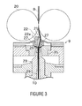
FIG. 3 is a cross-sectional view of a spinning device; -
FIG. 4 is a side view illustrating a state in which a yarn breakage occurred in the spinning unit; -
FIG. 5 is a side view illustrating a state of sucking and catching the spun yarn with a yarn catching section of the yarn joining cart; -
FIG. 6 is a side view illustrating a state in which the spun yarn is guided by the yarn catching section of the yarn joining cart; -
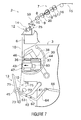
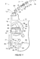
FIG. 7 is a side view illustrating a state in which the yarn joining device is advanced to a yarn joining position; -
FIG. 8 is a cross-sectional side view of the yarn joining device when the yarn is clamped by a clamp section; -
FIG. 9 is a cross-sectional side view of the yarn joining device illustrating a state in which yarn ends are untwisted; -
FIG. 10 is a cross-sectional side view of the yarn joining device illustrating a state in which the yarn ends are twisted; -
FIG. 11 is a side view illustrating a state immediately after a winding of the spun yarn is resumed after a yarn joining operation is finished; and -
FIG. 12 is a cross-sectional side view of the yarn joining device illustrating a state in which a yarn joint is passed through a yarn joint monitor. - A fine spinning machine serving as a yarn winding machine according to one embodiment of the present invention will be described with reference to the drawings. A fine spinning machine (spinning machine) 1 illustrated in
FIG. 1 includes a plurality of spinning units (yarn winding units) 2 arranged in line, ayarn joining cart 3, ablower box 80, and amotor box 5. - A negative pressure source (not illustrated) or the like for supplying negative pressure to each
spinning unit 2 is arranged in theblower box 80. A common drive source for thespinning units 2 is arranged in themotor box 5. - As illustrated in
FIG. 2 , each spinningunit 2 includes adraft device 7, a spinning device (yarn supplying section) 9, ayarn accumulating device 12, and a winding device (winding section) 13 arranged in this order from upstream to downstream. Eachspinning unit 2 is adapted to spin afiber bundle 8 fed from thedraft device 7 by thespinning device 9 to produce a spunyarn 10, and winds the spunyarn 10 around abobbin 48 with the windingdevice 13. Thebobbin 48 wound with the spunyarn 10 is referred to as apackage 45. "Upstream" and "downstream" respectively refer to upstream and downstream in a travelling direction of thefiber bundle 8 and the spunyarn 10 during a normal winding. The normal winding refers to a state in which the spunyarn 10 between the spinningdevice 9 and the windingdevice 13 is in continuation and thepackage 45 is rotatably driven at a substantially prescribed peripheral speed so that the spunyarn 10 is wound at a substantially prescribed speed. - The
draft device 7 is arranged in proximity to an upper end of aframe 6 of the fine spinning machine 1. Thedraft device 7 includes four draft rollers, i.e. , aback roller 16, a third roller 17, a middle roller 19 provided with a rubber apron belt 18, and afront roller 20 in this order from the upstream. Each draft roller is rotatably driven at a predetermined rotation speed. Thedraft device 7 includes opposing rollers arranged to face the draft rollers. Thedraft device 7 sandwiches and transports asliver 15, which is a raw material of thefiber bundle 8, between the rotating draft rollers and the opposing rollers opposing thereto, and thesliver 15 is drafted to a predetermined width to obtain thefiber bundle 8. - The
spinning device 9 is arranged immediately downstream of thefront roller 20. Thefiber bundle 8 drafted by thedraft device 7 is supplied to thespinning device 9. Thespinning device 9 applies a twist to thefiber bundle 8 supplied from thedraft device 7 to produce the spunyarn 10. The spunyarn 10 produced by thespinning device 9 is wound by the windingdevice 13. Therefore, thespinning device 9 is the yarn supplying section adapted to supply the spunyarn 10 to the windingdevice 13. - In the fine spinning machine 1 of the present embodiment, an air-jet spinning device which uses whirling airflow to apply the twist to the
fiber bundle 8 is adopted as thespinning device 9. As illustrated inFIG. 3 , thespinning device 9 includes anozzle block 35, a hollowguide shaft body 23, and afiber guiding section 22. - A spinning
chamber 26 is formed between thenozzle block 35 and the hollowguide shaft body 23. Anair injecting nozzle 27 is formed in thenozzle block 35. The air is injected from theair injecting nozzle 27 into the spinningchamber 26, and the whirling airflow is generated in the spinningchamber 26. An introducingport 21 for introducing thefiber bundle 8 into the spinningchamber 26 is formed in thefiber guiding section 22. - The
fiber bundle 8 supplied from thedraft device 7 is guided into the spinningchamber 26 by thefiber guiding section 22 having the introducingport 21. In the spinningchamber 26, thefiber bundle 8 is swung around a periphery of the hollowguide shaft body 23 by the whirling airflow, and the twist is applied to produce the spunyarn 10. The twisted spunyarn 10 is passed through ayarn passage 29 formed at an axial center of the hollowguide shaft body 23, and fed to an outside of thespinning device 9 from a yarn exit (not illustrated) on the downstream of the hollowguide shaft body 23. - A needle-
like guide needle 22a is arranged in the introducingport 21, and a tip of theguide needle 22a is directed towards the spinningchamber 26. Thefiber bundle 8 introduced from theyarn introducing port 21 is guided into the spinningchamber 26 so as to be wound around theguide needle 22a. Accordingly, a state of thefiber bundle 8 introduced into the spinningchamber 26 can be stabilized. Since thefiber bundle 8 is guided so as to be wound around theguide needle 22a, even if a twist is applied to the fiber in the spinningchamber 26, the twist is prevented from being propagated to the upstream of thefiber guiding section 22. Accordingly, the twist applied by thespinning device 9 is prevented from influencing thedraft device 7. However, theguide needle 22a may be omitted, and a downstream end of thefiber guiding section 22 may function as theguide needle 22a. - As illustrated in
FIG. 2 , the windingdevice 13 is arranged downstream of thespinning device 9. The windingdevice 13 includes acradle arm 71, a windingdrum 72, and atraverse device 75. - The winding
drum 72 is rotatably driven in one direction at a prescribed rotation speed. Thecradle arm 71 can rotatably support thebobbin 48 for winding the spunyarn 10. Thecradle arm 71 is supported to be swingable about a supportingshaft 73. When thecradle arm 71 is swung about the supportingshaft 73 while supporting the bobbin 48 (or thepackage 45 formed by winding the spunyarn 10 around the bobbin 48), the outer periphery of the bobbin 48 (or the package 45) makes contact with or is located away from the windingdrum 72. By causing the outer periphery of the bobbin 48 (or the package 45) to make contact with the rotatably-driven windingdrum 72, the bobbin 48 (or the package 45) is rotated in one direction accompanying the rotation of the windingdrum 72, and the spunyarn 10 can be wound around the bobbin 48 (or the package 45). In the following description, a direction in which the windingdrum 72 rotates thepackage 45 is referred to as a "winding direction". The windingdrum 72 of the windingdevice 13 in eachspinning unit 2 is rotatably driven simultaneously by the common drive source (not illustrated) for the plurality of spinningunits 2. The drive source is provided in themotor box 5. Accordingly, thepackage 45 can be rotated simultaneously at the same peripheral speed in the plurality of spinningunits 2, and thus the spunyarn 10 can be wound simultaneously. - The
traverse device 75 includes thetraverse guide 76 capable of being engaged with the spunyarn 10. Thetraverse guide 76 is reciprocated in a direction parallel to an axial direction of the windingdrum 72 by a driving means (not illustrated). The driving means is arranged in themotor box 5. The windingdrum 72 is rotatably driven while reciprocating thetraverse guide 76 engaged with the spunyarn 10, and the spunyarn 10 is wound into thepackage 45 while being traversed. - The
yarn accumulating device 12 is arranged between the spinningdevice 9 and the windingdevice 13. As illustrated inFIG. 2 , theyarn accumulating device 12 includes ayarn accumulating roller 14 and anelectric motor 25 for rotatably driving theyarn accumulating roller 14. - The
yarn accumulating roller 14 can have a prescribed amount of the spunyarn 10 wound around the outer peripheral surface thereof to temporarily accumulate the spunyarn 10. When theyarn accumulating roller 14 is rotated at a predetermined rotation speed with the spunyarn 10 wound around the outer peripheral surface of theyarn accumulating roller 14, the spunyarn 10 can be pulled out at a predetermined speed from thespinning device 9 and transported towards the downstream. Since theyarn accumulating device 12 can temporarily accumulate the spunyarn 10 on the outer peripheral surface of theyarn accumulating roller 14, theyarn accumulating device 12 functions as one type of buffer between the spinningdevice 9 and the windingdevice 13. Accordingly, a drawback (e.g., slackening of the spunyarn 10 or the like) when a spinning speed in thespinning device 9 and a winding speed in the windingdevice 13 do not match for some reason can be resolved by theyarn accumulating device 12. - Yarn
quality measuring equipment 59 is arranged at a position between the spinningdevice 9 and theyarn accumulating device 12. The spunyarn 10 spun by thespinning device 9 is passed through the yarnquality measuring equipment 59 before being wound by theyarn accumulating device 12. The yarnquality measuring equipment 59 monitors a thickness of the travelling spunyarn 10 with a capacitance sensor (not illustrated). When a yarn defect (area where abnormality is found in thickness or the like of the spun yarn 10) of the spunyarn 10 is detected, the yarnquality measuring equipment 59 transmits a yarn defect detection signal to a unit controller (not illustrated). The yarnquality measuring equipment 59 is not limited to the capacitance sensor and may be a light transmissive sensor (optical sensor). The yarnquality measuring equipment 59 may detect a foreign substance contained in the spunyarn 10 as a yarn defect. - A cutter (not illustrated) arranged in proximity to the yarn
quality measuring equipment 59 immediately cuts the spunyarn 10 when the yarn defect of the spunyarn 10 is detected by the yarnquality measuring equipment 59. Instead of using the cutter, thespinning unit 2 may stop the supply of air to thespinning device 9 and cut the spunyarn 10 by interrupting the production of the spunyarn 10. - As illustrated in
FIG. 1 , theframe 6 of the fine spinning machine 1 includes a yarn joiningcart travelling rail 41 along a direction in which thespinning units 2 are arranged. Theyarn joining cart 3 travels on the yarn joiningcart travelling rail 41. Accordingly, theyarn joining cart 3 can travel among the plurality of spinningunits 2. - As illustrated in
FIG. 1 andFIG. 2 , theyarn joining cart 3 includes ayarn joining device 43, a yarn catching section (asuction pipe 44 and a suction mouth 46), a yarn joint monitor (a yarn-joint monitoring device) 47, a reverse-rotation driving mechanism 49, and a movingmeans 30. Theyarn joining cart 3 includes a cart control section (not illustrated) for controlling each component of theyarn joining cart 3. - The
suction pipe 44 and thesuction mouth 46 can respectively swing vertically with an axis as the center. Thesuction pipe 44 generates suction airflow at a tip-end thereof to suck and catch the spunyarn 10 fed from the spinning device 9 (seeFIG. 5 ). Thesuction mouth 46 generates suction airflow at a tip-end thereof to suck and catch the spunyarn 10 from thepackage 45 supported by the winding device 13 (seeFIG. 5 ). Thesuction pipe 44 and thesuction mouth 46 swing while keeping the sucked and caught spunyarn 10 to guide the spunyarn 10 to a position facing a front side (left side ofFIG. 6 ) of the yarn joining device 43 (a state ofFIG. 6 ). Operations of thesuction pipe 44 and thesuction mouth 46 are controlled by the cart control section. - The
yarn joining device 43 can perform the yarn joining operation (join) the spunyarn 10 from thespinning device 9 guided by thesuction pipe 44 and the spunyarn 10 from thepackage 45 guided by thesuction mouth 46. Theyarn joining device 43 is configured as a splicer device adapted to form a yarn joint 99 by applying a twist to the yarn ends with the whirling airflow. The configuration of theyarn joining device 43 is not limited thereto, and may be a mechanical knotter, for example. Formation of the yarn joint 99 by theyarn joining device 43 is controlled by the cart control section. When theyarn joining cart 3 stops at thespinning unit 2, theyarn joining device 43 is located between the windingdevice 13 and theyarn accumulating device 12 in the travelling direction of the spunyarn 10. - The moving means 30 can move the
yarn joining device 43 in a direction of advancing towards or receding from the yarn path during the normal winding (travelling path of the spunyarn 10, vertical direction in plane of drawing inFIG. 2 ). Theyarn joining device 43 carries out the yarn joining operation at a position located close to the yarn path during the normal winding (e.g., a position illustrated inFIG. 7 ). The position of theyarn joining device 43 at this time is referred to as a "yarn joining position" (or an advanced position). When the yarn joining operation is not carried out, theyarn joining device 43 is retreated to a position located away from the yarn path during the normal winding (e.g., a position illustrated inFIG. 2 ). The position of theyarn joining device 43 at this time is referred to as a "retreated position" (or a receded position). - The moving means 30 includes a
rail 37, and an air cylinder (movement driving source) 38. Therail 37 is arranged in a cart main body of theyarn joining cart 3. Therail 37 has a linear elongate form, and arranged such that a longitudinal direction thereof is along a direction substantially orthogonal to the yarn path during the normal winding (front and back direction of thespinning unit 2, left and right direction in plane of drawing inFIG. 2 ). Theyarn joining device 43 is attached to a supportingbracket 36. The supportingbracket 36 is supported by therail 37, and is movable along the longitudinal direction of therail 37. Therefore, theyarn joining device 43 attached to the supportingbracket 36 is movable in a direction substantially orthogonal to the yarn path during the normal winding. - The
air cylinder 38 is a movement driving source for driving theyarn joining device 43 along therail 37. One end the of theair cylinder 38 is attached to the cart main body of theyarn joining cart 3, and the other end is attached to the supportingbracket 36. By extending and contracting theair cylinder 38, theyarn joining device 43 can be linearly moved in the direction along the rail 37 (direction orthogonal to the yarn path during the normal winding). The extending and contracting operation of theair cylinder 38 is controlled by the cart control section. - Next, a structure of the
yarn joining device 43 will be described with reference toFIG. 10 . Theyarn joining device 43 includes ayarn joining nozzle 94, aclamp section 97, a yarn path regulating member (yarn guiding levers 96 and yarn controlling levers 98),cutters 92, and untwistingpipes 82. - The yarn joining nozzle (twisting section) 94 is arranged on the front side of the main body of the
yarn joining device 43. Ayarn joining hole 90, through which the spunyarn 10 can be passed, is formed in theyarn joining nozzle 94. An injection port (not illustrated) for injecting compressed air is formed on an inner side of theyarn joining hole 90. By injecting the compressed air into theyarn joining hole 90 from the injection port, theyarn joining nozzle 94 generates the whirling airflow inside theyarn joining hole 90. - The
yarn joining device 43 includes two untwisting pipes (untwisting section) 82. The two untwistingpipes 82 are formed in an elongate cylindrical shape, and longitudinal directions thereof are arranged to be parallel to each other in a front and back direction of theyarn joining device 43. The two untwistingpipes 82 are arranged in line in a direction substantially parallel to the yarn travelling direction, and each untwistingpipe 82 has one end opened to a front side of theyarn joining device 43. An air injecting hole is formed in each of the untwistingpipes 82 for generating an airflow directed towards a rear side (side opposite to the yarn path) by injecting the compressed air to the inner side of the untwistingpipes 82. - The
yarn joining nozzle 94 and the untwistingpipes 82 are both fixedly arranged to the main body of theyarn joining device 43. When the moving means 30 moves theyarn joining device 43, theyarn joining nozzle 94 and the untwistingpipes 82 integrally move with the main body of theyarn joining device 43. - The yarn path regulating member (the yarn guiding levers 96 and the yarn controlling levers 98) are lever-like members swingably arranged in the main body of the
yarn joining device 43. InFIG. 8 to FIG. 10 andFIG. 12 , only the cross-sections of the yarn guiding levers 96 and the yarn controlling levers 98 are illustrated. The yarn guiding levers 96 and the yarn controlling levers 98 are arranged capable of regulating the yarn path of the spunyarn 10 by making contact with the spunyarn 10.FIG. 8 and the like illustrate a state in which the yarn path is regulated by the yarn guiding levers 96 and the yarn controlling levers 98. The yarn guiding levers 96 and the yarn controlling levers 98 can be swung to a position of not making contact with the spunyarn 10. Accordingly, the spunyarn 10 regulated by the yarn guiding levers 96 and the yarn controlling levers 98 can be released. - One
clamp section 97 is arranged above and below theyarn joining nozzle 94, respectively, in the yarn travelling direction. Theclamp sections 97 are configured to be openable/closable, and can clamp the spunyarn 10 in a closed state. Onecutter 92 is arranged above and below theyarn nozzle 94, respectively, in the yarn travelling direction. Thecutters 92 can cut the spunyarn 10. - The
yarn joining device 43 includes a cam mechanism (not illustrated) for causing the swinging operation of the yarn guiding levers 96 and the yarn controlling levers 98, the open/close operation of theclamp sections 97, and the cutting operation by thecutters 92 to be performed. Theyarn joining device 43 includes anelectric motor 60, which is a drive source of the cam mechanism. By appropriately controlling the operation of theelectric motor 60, the clamping and cutting of the spunyarn 10, as well as, the regulation of the yarn path can be carried out at an appropriate timing. An operation of theelectric motor 60 is controlled by the cart control section. As illustrated inFIG. 2 and the like, theelectric motor 60 is arranged in proximity to the main body of theyarn joining device 43, and is fixed with respect to the main body of theyarn joining device 43. When the moving means 30 moves theyarn joining device 43, theelectric motor 60, the cam mechanism, and the members driven by the cam mechanism (the yarn guiding levers 96, the yarn controlling levers 98, theclamp sections 97, and the cutters 92) are integrally moved. Accordingly, theelectric motor 60, theclamp sections 97, and the like can be moved between an activating position and a non-activating position, the activating position being a position located close to the yarn path of the spunyarn 10 to be activated, and the non-activating position being a position located away from the yarn path. - Assume that the
electric motor 60, which is the drive source of the cam mechanism, is arranged on the cart main body of theyarn joining cart 3 apart from theyarn joining device 43. In this case, if theyarn joining device 43 is moved, the positional relationship between theelectric motor 60 and the cam mechanism changes. An assumption can be made that it is difficult to configure a drive transmission path from theelectric motor 60 to the cam mechanism. In the present embodiment, theyarn joining device 43 itself includes theelectric motor 60, and theelectric motor 60, the cam mechanism, and the members driven by the cam mechanism move integrally. Thus, a configuration of moving theyarn joining device 43 can be easily realized. - The yarn
joint monitor 47 is arranged immediately downstream of theyarn joining device 43 to measure the quality of the spunyarn 10 that has been joined by theyarn joining device 43. In the present embodiment, the yarnjoint monitor 47 monitors a thickness of the yarn joint 99 formed by theyarn joining device 43 with a capacitance sensor. The yarnjoint monitor 47 may be, for example, a light transmissive sensor (optical sensor). Information detected by the yarnjoint monitor 47 is transmitted to the cart control section. The yarnjoint monitor 47 is fixed to the supportingbracket 36. When the moving means 30 moves theyarn joining device 43, the yarnjoint monitor 47 moves simultaneously with theyarn joining device 43. - Next, the reverse-
rotation driving mechanism 49 will be described. As illustrated inFIG. 2 and the like, the reverse-rotation driving mechanism 49 includes a first supportingarm 61 and a second supportingarm 62, a reversely-rotatingroller 63, and a reversely-rotating roller driving motor (not illustrated), which is a drive source of the reversely-rotatingroller 63. - The reversely-rotating
roller 63 is rotatably driven by a driving force from the reversely-rotating roller driving motor (not illustrated). An operation of the reversely-rotating roller driving motor is controlled by the cart control section. - One end side of the first supporting
arm 61 is rotatably attached to a housing main body of theyarn joining cart 3. The second supportingarm 62 is swingably provided on the other end side of the first supportingarm 61. The reversely-rotatingroller 63 is rotatably arranged at a tip-end of the second supportingarm 62. Theyarn joining cart 3 includes alink rod 64 swingably arranged with respect to the housing of theyarn joining cart 3. A tip-end of thelink rod 64 is coupled to the second supportingarm 62. A reversely-rotating roller advancing-and-recedingair cylinder 66 is attached to thelink rod 64. Thelink rod 64 can be swung by advancement and the recession of the reversely-rotating roller advancing-and-recedingair cylinder 66. - The first supporting
arm 61, the second supportingarm 62, and thelink rod 64 configure a link mechanism. By extending and contracting the reversely-rotating roller advancing-and-recedingair cylinder 66 connected to the link mechanism, the reversely-rotatingroller 63 at the tip-end of the second supportingarm 62 can be made to advance and recede. The reversely-rotatingroller 63 thus can be moved between a "retreated position" of not making contact with the package 45 (e.g., the position illustrated inFIG. 2 ) and a "contacting position" of making contact with the package 45 (e.g., a position illustrated inFIG. 5 ). An operation of the reversely-rotating roller advancing-and-recedingair cylinder 66 is controlled by the cart control section. - Next, the yarn joining operation by the
yarn joining cart 3 will be described. The yarn joining operation is carried out when the spunyarn 10 between the spinningdevice 9 and thepackage 45 is disconnected due to some reason in acertain spinning unit 2. - In a
certain spinning unit 2, for example, when the spunyarn 10 between the spinningdevice 9 and thepackage 45 is disconnected as inFIG. 4 , the unit controller of thespinning unit 2 carries out a control to swing and drive thecradle arm 71 to move thepackage 45 away from the windingdrum 72, and activates a brake mechanism (not illustrated) arranged in the windingdevice 13. As a result, thepackage 45 stops the rotation. - The unit controller then transmits a control signal to the
yarn joining cart 3. Theyarn joining cart 3 that received the control signal travels to thetarget spinning unit 2 on the yarn joiningcart travelling rail 41 and stops thereat. Theyarn joining device 43 is thus located at the operating position. When theyarn joining cart 3 travels along the spinningunits 2, the moving means 30 retreats theyarn joining device 43 to the retreated position. If theyarn joining device 43 is advanced to a position close to the yarn path when theyarn joining cart 3 travels, theyarn joining device 43 makes contact with the spunyarn 10 wound by each spinningunit 2, and a yarn breakage may occur. When theyarn joining cart 3 travels, since theyarn joining device 43 is retreated to a position located away from the yarn path (retreated position), theyarn joining device 43 is prevented from making contact with the spunyarn 10. - As illustrated in
FIG. 5 , when theyarn joining cart 3 stops at thetarget spinning unit 2, the cart control section rotates thesuction pipe 44 and thesuction mouth 46 to respectively suck and catch the yarn end from thespinning device 9 and the yarn end from thepackage 45. - In this case, the cart control section advances the reversely-rotating
roller 63 to the contacting position and rotatably drives the reversely-rotatingroller 63 in a direction opposite to the windingdrum 72. Accordingly, thepackage 45 is rotatably driven in a direction opposite to the winding direction (hereinafter referred to as an unwinding direction). Under this state, when the spunyarn 10 at the surface of thepackage 45 is sucked by thesuction mouth 46, the spunyarn 10 is pulled out from thepackage 45 and caught by thesuction mouth 46. - Then, by swinging the
suction pipe 44 and thesuction mouth 46 in the opposite direction while keeping the caught spunyarn 10, the cart control section guides the caught spunyarn 10 to a position facing the front side of the yarn joining device 43 (a state ofFIG. 6 ). Until the guiding of the spunyarn 10 by thesuction pipe 44 and thesuction mouth 46 is completed, the movingmeans 30 maintains theyarn joining device 43 at the retreated position. By retreating theyarn joining device 43 to a position located away from the yarn path, thesuction pipe 44 and thesuction mouth 46 to be swung are prevented from making contact with theyarn joining device 43. - When the guiding of the spun
yarn 10 by thesuction pipe 44 and thesuction mouth 46 is finished, the cart control section stops the rotation of the reversely-rotatingroller 63. Then, the movingmeans 30 extends theair cylinder 38 to a limit of a stroke length, and moves theyarn joining device 43 in a direction of approaching the yarn path to advance to the yarn joining position. When theyarn joining device 43 is advanced to the yarn joining position, the spunyarn 10 from thespinning device 9 caught by thesuction pipe 44 and the spunyarn 10 from thepackage 45 caught by thesuction mouth 46 are guided to the yarn joining device 43 (a state ofFIG. 7 ). Thus, according to the present embodiment, since theyarn joining device 43 itself can advance towards the yarn path, the yarn path is not required to be greatly bent to introduce the spunyarn 10 into theyarn joining device 43. The spunyarn 10 can be introduced into theyarn joining device 43 in a state close to the yarn path during the normal winding (a state in which yarn path is not greatly bent). - Since there is a limit to the stroke length of the
air cylinder 38, theyarn joining device 43 does not move beyond the stroke length. That is, theair cylinder 38 itself has a function as a stopper mechanism for determining a moving end position (a yarn joining position) of theyarn joining device 43. A stopper member for determining the position of the yarn joining position of theyarn joining device 43 may be arranged separately from theair cylinder 38. - As illustrated in
FIG. 7 and the like, the yarnjoint monitor 47 is arranged such that when the moving means 30 advances theyarn joining device 43 to the yarn joining position, the spunyarn 10 is introduced into the yarnjoint monitor 47. The spunyarn 10 thus can be monitored by the yarnjoint monitor 47. Since the yarnjoint monitor 47 itself can be advanced towards the yarn path, and a member for introducing the spunyarn 10 into the yarnjoint monitor 47 is unnecessary. As illustrated inFIG. 2 and the like, when the moving means 30 retreats theyarn joining device 43 to the retreated position, the spunyarn 10 is not introduced into the yarnjoint monitor 47. Thus, when theyarn joining cart 3 travels, the yarnjoint monitor 47 is prevented from interfering with the yarn path of the spunyarn 10. - When the
yarn joining device 43 is advanced to the yarn joining position, the cart control section swings the yarn guiding levers 96 to cause the yarn guiding levers 96 to make contact with the spunyarn 10. Accordingly, the spunyarn 10 between thepackage 45 and thesuction mouth 46 and the spunyarn 10 between the spinningdevice 9 and thesuction pipe 44 are respectively bent by the yarn guiding levers 96, and the yarn path of the spunyarn 10 is regulated. The yarn guiding levers 96 guide the spunyarn 10 to a position where the spunyarn 10 can be clamped by the clamp sections 97 (a state ofFIG. 8 ). The cart control section closes theclamp sections 97 under this state, and the spunyarn 10 is clamped by theclamp sections 97. In the present embodiment, since the members (the yarn guiding levers 96) for guiding the spunyarn 10 are arranged in theyarn joining device 43, when the moving means 30 advances theyarn joining device 43 to the yarn joining position, the yarn guiding levers 96 can also be advanced to a position in proximity to the yarn path. Therefore, the spunyarn 10 can be reliably guided to theyarn joining hole 90 of theyarn joining nozzle 94 by the yarn guiding levers 96. Since theyarn joining nozzle 94 is also advanced to a position close to the yarn path, the distance in which the spunyarn 10 is to be guided by the yarn guiding levers 96 is reduced and the bending of the yarn path when the spunyarn 10 is guided to theyarn joining hole 90 can be reduced. - Then, the cart control section starts the injection of the compressed air into the untwisting
pipes 82. The airflow directed towards the rear side of the yarn joining device 43 (right side in the drawing ofFIG. 8 ) is thus generated in the untwistingpipes 82, and suction airflow is generated at an opening on the front side of the untwisting pipes 82 (left side in the drawing ofFIG. 8 ). Before or after this operation, the cart control section operates thecutters 92 to cut the spunyarn 10 between thesuction pipe 44 and theyarn joining device 43 and the spunyarn 10 between thesuction mouth 46 and theyarn joining device 43 . The yarn ends formed by the cutting are sucked by the untwistingpipes 82, and pulled into the untwistingpipes 82. The pulled-in yarn ends are subjected to the action of the airflow in the untwistingpipes 82 so that the twisting of the fiber is resolved and untwisted (FIG. 9 ). - When the untwisting of the yarn ends is finished, the cart control section terminates the injection of the compressed air into the untwisting
pipes 82. Furthermore, the cart control section further bends the yarn path of the spunyarn 10 by the yarn guiding levers 96 and the yarn controlling levers 98, and pulls out the untwisted yarn ends from the untwistingpipes 82. The yarn ends pulled out from the untwistingpipes 82 are set to overlap each other in theyarn joining hole 90 of the yarn joining nozzle 94 (FIG. 10 ). When the compressed air is injected into theyarn joining hole 90 under this state, the whirling flow is generated in theyarn joining hole 90 to twist the fiber. Accordingly, the yarn end of the spunyarn 10 from thespinning device 9 and the yarn end of the spunyarn 10 from thepackage 45 are twisted together and connected to form ayarn joint 99. - After the yarn joint 99 is formed, the cart control section stops the injection of air into the
yarn joining hole 90. Further, the cart control section opens theclamp sections 97 to release the clamped spunyarn 10, and releases the regulation of the yarn path by the yarn guiding levers 96 and the yarn controlling levers 98. Before or after this operation, the unit controller of thespinning unit 2 swings thecradle arm 71 to cause the outer peripheral surface of thepackage 45 to make contact with the rotating winding drum 72 (a state ofFIG. 11 ). The stoppedpackage 45 thus resumes the rotation in the winding direction, and the winding of the spunyarn 10 is resumed. - In the fine spinning machine 1 of the present embodiment, the
yarn joining device 43 itself advances to the yarn path to perform the yarn joining operation. As illustrated inFIG. 11 , the yarn path when resuming the winding of the spunyarn 10 may be located close to the yarn path during the normal winding (a state of not being bent greatly). Therefore, after the yarn joining operation is finished, the slackening of the spunyarn 10 when the winding of the spunyarn 10 is resumed can be suppressed to a minimum. - As illustrated in
FIG. 12 , when the winding of the spunyarn 10 is resumed, a yarn joint 99 formed in theyarn joining device 43 is passed through the yarnjoint monitor 47. The yarn joint 99 is monitored by the yarnjoint monitor 47. The cart control section determines the quality of the yarn joint 99 based on a monitoring result by the yarnjoint monitor 47. For example, if the yarn joint 99 is a defective yarn joint that does not satisfy a dimensional condition of predetermined thickness, length, or the like, theyarn joining cart 3 cuts and removes the defective yarn joint with the cutter (not illustrated) and performs the yarn joining operation again by theyarn joining device 43. - After the monitoring of the yarn joint 99 by the yarn
joint monitor 47 is finished, the moving means 30 moves theyarn joining device 43 to the retreated position. Accordingly, theyarn joining cart 3 is able to travel, and can travel to anotherspinning unit 2. When the moving means 30 causes theyarn joining device 43 to retreat to the retreated position, the yarn guiding levers 96 and the like arranged in theyarn joining device 43 are also caused to retreat to the position located away from the yarn path. Since the yarn guiding levers 96 can be retreated when the yarn guiding levers 96 are not operated, a structure of theyarn joining cart 3 can be made small. - As described above, the fine spinning machine 1 of the present embodiment includes the winding
device 13 adapted to wind the spunyarn 10 into thepackage 45, thespinning device 9 adapted to supply the spunyarn 10 to the windingdevice 13, theyarn joining device 43 adapted to perform a yarn joining operation to join the spunyarn 10 between thepackage 45 and thespinning device 9 at the operating position, and the movingmeans 30. The moving means 30 can move theyarn joining device 43 at the operating position to the yarn joining position and the retreated position, the yarn joining position being a position located close to the yarn path between thepackage 45 and thespinning device 9 during the normal winding, and the retreated position being a position located away from the yarn path. - Thus, the
yarn joining device 43 can be advanced towards the yarn path only when necessary. In other words, theyarn joining device 43 can be retreated so that theyarn joining device 43 does not interfere with the yarn path during the normal winding. When the yarn joining operation is required, theyarn joining device 43 is advanced to the yarn path and the spunyarn 10 can be introduced into theyarn joining device 43. Therefore, theyarn joining device 43 itself can be brought close to the yarn path, and hence the yarn path is not required to be greatly bent to introduce the spunyarn 10 to theyarn joining device 43. As a result of reduction in the bending of the spunyarn 10, the slackening of the spunyarn 10 can be prevented. Therefore, the spunyarn 10 can be prevented from being wound into thepackage 45 in a slackened state, and the quality of thepackage 45 produced by the fine spinning machine 1 can be improved. The slackened spunyarn 10 can be prevented from getting caught at the surrounding members. - In the fine spinning machine 1 of the present embodiment, the
yarn joining device 43 includes the untwistingpipes 82 adapted to untwist the yarn end from thepackage 45 and the yarn end from thespinning device 9, and theyarn joining nozzle 94 adapted to twist the untwisted yarn ends. The moving means 30 moves the untwistingpipes 82 and theyarn joining nozzle 94 to the yarn joining position located close to the yarn path and the retreated position located away from the yarn path. - Accordingly, the untwisting and twisting can be carried out in proximity to the yarn path. As a result, the yarn joining operation can be carried out without greatly bending the spun
yarn 10 from the yarn path during the normal winding. - The fine spinning machine 1 of the present embodiment includes a yarn catching section (the
suction pipe 44 and the suction mouth 46) adapted to catch the spunyarn 10 from thepackage 45 and the spunyarn 10 from thespinning device 9 when the spunyarn 10 between thepackage 45 and thespinning device 9 is disconnected. The moving means 30 maintains theyarn joining device 43 at the retreated position during the normal winding, and advances theyarn joining device 43 to the yarn joining position during the yarn joining operation. The yarn catching section guides the caught spunyarn 10 to a position where the spunyarn 10 can be introduced into theyarn joining device 43 located at the yarn joining position. - Accordingly, the spun
yarn 10 can be guided to theyarn joining device 43 located at the yarn joining position, and the yarn joining operation by theyarn joining device 43 can be performed. - In the fine spinning machine 1 of the present embodiment, the yarn catching section guides the spun
yarn 10 by swinging while keeping the caught spunyarn 10. After the yarn catching section completes the guiding of the spunyarn 10, the moving means 30 starts to advance theyarn joining device 43 from the retreated position to the yarn joining position. - In other words, when swinging the yarn catching section, the
yarn joining device 43 is retreated to the position located away from the yarn path to prevent the swinging yarn catching section from interfering with theyarn joining device 43. As a result, the degree of freedom in the layout of the yarn catching section is improved. - The fine spinning machine 1 of the present embodiment includes a plurality of spinning
units 2 and theyarn joining cart 3. Thespinning unit 2 includes thespinning device 9 and the windingdevice 13. Theyarn joining cart 3 includes ayarn joining device 43, and can travel to the plurality of spinningunits 2 and stop in proximity of thespinning unit 2 in which the spunyarn 10 is disconnected to perform the yarn joining operation to thetarget spinning unit 2 by theyarn joining device 43. When theyarn joining cart 3 travels, the movingmeans 30 maintains theyarn joining device 43 at the retreated position. - Accordingly, since the
yarn joining cart 3 travels with theyarn joining device 43 retreated to the position located away from the yarn path, theyarn joining device 43 is prevented from making contact with the spunyarn 10 being wound by each spinningunit 2. - In the fine spinning machine 1 of the present embodiment, the moving
means 30 is adapted to linearly move theyarn joining device 43 in a direction substantially orthogonal to the yarn path between thepackage 45 and thespinning device 9 during the normal winding. The distance of moving theyarn joining device 43 with respect to the yarn path thus can be reduced. - In the fine spinning machine 1 of the present embodiment, the
yarn joining device 43 further includes theclamp sections 97 adapted to clamp the spunyarn 10 during the yarn joining operation, and theelectric motor 60 which is a drive source for theclamp sections 97. The moving means 30 moves theclamp sections 97 and theelectric motor 60 to the activating position located close to the yarn path and the non-activating position located away from the yarn path. Accordingly, theyarn joining device 43 can be moved with respect to the yarn path to perform the yarn joining operation. - The fine spinning machine 1 of the present embodiment includes the yarn
joint monitor 47 adapted to monitor a quality of the yarn joint formed by the yarn joining operation of theyarn joining device 43. The moving means 30 simultaneously moves the yarnjoint monitor 47 and theyarn joining device 43. - Accordingly, the yarn
joint monitor 47 can be moved in a direction of advancing towards the yarn path, and the yarn joint of the spunyarn 10 can be monitored by the yarnjoint monitor 47. If the yarn joint is not required to be monitored by the yarnjoint monitor 47, the yarnjoint monitor 47 can be retreated to the position located away from the yarn path so that the yarnjoint monitor 47 can be prevented from interfering with the yarn path. According to the present embodiment, the slackening of the spunyarn 10 during the yarn joining operation can be prevented, and the monitoring accuracy of the yarn joint 99 by the yarnjoint monitor 47 can be improved. - In the fine spinning machine 1 of the present embodiment, the moving
means 30 includes therail 37 and theair cylinder 38. Therail 37 guides theyarn joining device 43 between the yarn joining position and the retreated position. Theair cylinder 38 moves theyarn joining device 43 along therail 37. By guiding theyarn joining device 43 with therail 37, theyarn joining device 43 can be moved on an accurate path along the direction of advancing towards or receding from the yarn path. - In the fine spinning machine 1 of the present embodiment, the
air cylinder 38 also functions as a stopper mechanism for defining an end of a movable range in which theyarn joining device 43 can be moved in a direction to approach the yarn path. Thus, theyarn joining device 43 can be prevented from excessively approaching the yarn path during the yarn joining operation, and the yarn joining operation can be performed while appropriately maintaining the positional relationship of theyarn joining device 43 and the yarn path. - The fine spinning machine 1 of the present embodiment includes the
yarn accumulating device 12 arranged between the spinningdevice 9 and the windingdevice 13, and adapted to temporarily accumulate the spunyarn 10 around the outer peripheral surface of the rotatingyarn accumulating roller 14. Theyarn joining device 43 performs the yarn joining operation between theyarn accumulating device 12 and the windingdevice 13 in the travelling direction of the spunyarn 10. In other words, according to the present embodiment, since the slackening of the spunyarn 10 during the yarn joining operation can be prevented, the spunyarn 10 can be prevented from getting entangled around the rotatingyarn accumulating roller 14. Therefore, the spunyarn 10 can be appropriately accumulated by theyarn accumulating device 12. - The fine spinning machine 1 of the present embodiment includes the
traverse device 75 adapted to traverse the spunyarn 10 by thereciprocating traverse guide 76 before the spunyarn 10 is wound into thepackage 45. - In other words, according to the present embodiment, since the slackening of the spun
yarn 10 during the yarn joining operation can be prevented, the slackened spunyarn 10 can be prevented from getting caught at thereciprocating traverse guide 76 and causing a yarn breakage. Therefore, the spunyarn 10 can be appropriately traversed by thetraverse device 75. - The preferred embodiments of the present invention have been described above, but the structures described above may be modified as below.
- In the embodiment described above, a structure in which the
yarn joining cart 3 includes theyarn joining device 43 is adopted, but instead, the following structure may be adopted. In other words, thespinning unit 2 includes the windingdevice 13 adapted to wind the spunyarn 10 into thepackage 45, thespinning device 9 adapted to supply the spunyarn 10 to the windingdevice 13, theyarn joining device 43 adapted to perform a yarn joining operation to join the spunyarn 10 between thepackage 45 and thespinning device 9, and the movingmeans 30. The moving means 30 can move theyarn joining device 43 between the yarn joining position and the retreated position, the yarn joining position being a position located close to the yarn path between thepackage 45 and thespinning device 9 during the normal winding, and the retreated position being a position located away from the yarn path. - A structure in which each
spinning unit 2 includes theyarn joining device 43 may also be adopted. - The structure of the moving means 30 adapted to move the
yarn joining device 43 with respect to the yarn path is not limited to the above, and may be appropriately changed. For example, the drive source for moving theyarn joining device 43 with respect to the yarn path is not limited to theair cylinder 38, and may be a motor or the like. Theyarn joining device 43 is not necessarily moved so as to be orthogonal to the yarn path, and may be moved diagonally with respect to the yarn path. Instead of linearly moving on therail 37, theyarn joining device 43 may advance or recede from the yarn path by swinging with a supporting point as a center, for example. - In the embodiments described above, by rotating the
yarn accumulating roller 14 of theyarn accumulating device 12, the spunyarn 10 is pulled out from thespinning device 9. Alternatively, as described in Japanese Unexamined Patent Publication No.2005-220484 - The yarn
joint monitor 47 may move independently from theyarn joining device 43. However, in order to simplify the structure of the fine spinning machine 1, the movement of the yarnjoint monitor 47 and theyarn joining device 43 is desirably carried out simultaneously. - The structure for monitoring the yarn joint 99 formed by the
yarn joining device 43 may be omitted. In this case, the yarnjoint monitor 47 may be omitted. - In the embodiments described above, the travelling direction of the spun
yarn 10 is from top to bottom in a height direction. However, the travelling direction of the spunyarn 10 is not particularly limited thereto, and thespinning unit 2 may be structured such that the spunyarn 10 travels from the bottom to the top. - In
FIG. 2 and the like, the yarn path of the spunyarn 10 is in a substantially vertical direction. However, for example, the windingdevice 13 may be located more closer to the rear side of thespinning unit 2 than the position illustrated inFIG. 2 , and the yarn path may be formed inclining from the front side to the rear side. - In
FIG. 1 and the like, the fine spinning machine 1 includes oneyarn joining cart 3, but a plurality ofyarn joining carts 3 may be arranged in accordance with the number ofspinning units 2. - In the embodiments described above, the winding
drum 72 is commonly driven for the plurality of spinningunits 2. However, the windingdrum 72 may be individually driven in therespective spinning unit 2. In this case, the rotation speed and the rotating direction of the windingdrum 72 may be changed in eachspinning unit 2. Therefore, thepackage 45 can be reversely rotated by rotating the windingdrum 72 in the opposite direction, and the reversely-rotatingroller 63 may be omitted. - The structure of the
yarn joining device 43 is not limited to the above, and the present invention can be applied to theyarn joining device 43 of other structures. - The spinning device is not limited to an air-jet spinning device, and may be other types of spinning devices. The structure of the present invention is not limited to the spinning machine, and may be widely applied to other types of yarn winding machines such as an automatic winder.
Claims (12)
- A yarn winding machine comprising:a winding section (13) adapted to wind a yarn (10) into a package (45);a yarn supplying section (9) adapted to supply the yarn (10) to the winding section (13);a yarn joining device (43) adapted to perform a yarn joining operation to join the yarn (10) between the package (45) and the yarn supplying section (9) at an operating position; anda moving means (30) for moving the yarn joining device (43) at the operating position between an advanced position and a receded position, the advanced position being a position located close to a yarn path between the package (45) and the yarn supplying section (9) during a normal winding, and the receded position being a position located away from the yarn path.
- The yarn winding machine according to claim 1, wherein the yarn joining device (43) includes at least an untwisting section (82) adapted to untwist a yarn end from the package (45) and a yarn end from the yarn supplying section (9), and a twisting section (94) adapted to twist the untwisted yarn ends, and
the moving means (30) is adapted to move at least the untwisting section (82) and the twisting section (94) to the advanced position located close to the yarn path and the receded position located away from the yarn path. - The yarn winding machine according to claim 1 or claim 2, further comprising a yarn catching section (44, 46) adapted to catch a yarn (10) from the package (45) and a yarn (10) from the yarn supplying section (9) when the yarn (10) between the package (45) and the yarn supplying section (9) is disconnected,
wherein the moving means (30) is adapted to maintain the yarn joining device (43) at the receded position during the normal winding and to advance the yarn joining device (43) to the advanced position during the yarn joining operation, and
the yarn catching section (44, 46) guides the caught yarn (10) to a position where the yarn (10) can be guided into the yarn joining device (43) located at the advanced position. - The yarn winding machine according to claim 3, wherein the yarn catching section (44, 46) is adapted to guide the yarn (10) by swinging while keeping the caught yarn (10), and after the yarn catching section (44, 46) completes guiding the yarn (10), the moving means (30) starts to advance the yarn joining device (43) from the receded position to the advanced position.
- The yarn winding machine according to claim 3 or claim 4, further comprising:a plurality of yarn winding units (2), each yarn winding unit (2) including the yarn supplying section (9) and the winding section (13); anda yarn joining cart (3) including the yarn joining device (43) and being provided capable of travelling to at least some of the plurality of the yarn winding units (2), the yarn joining cart (3) is adapted to stop in proximity of a target yarn winding unit (2) in which the yarn (10) is disconnected and to perform the yarn joining operation to the target yarn winding unit (2) by the yarn joining device (43),wherein at least when the yarn joining cart (3) travels, the moving means (30) is adapted to maintain the yarn joining device (43) at the receded position.
- The yarn winding machine according to any one of claim 1 through claim 5, wherein the moving means (30) is adapted to linearly move the yarn joining device (43) in a direction substantially orthogonal to the yarn path between the package (45) and the yarn supplying section (9) during the normal winding.
- The yarn winding machine according to any one of claim 1 through claim 6, wherein the yarn joining device (43) further includes a clamp section (97) adapted to clamp the yarn (10) during the yarn joining operation, and a drive source (60) for the clamp section (97), and
the moving means (30) is adapted to move the clamp section (97) and the drive source (60) to an activating position located close to the yarn path and a non-activating position located away from the yarn path. - The yarn winding machine according to any one of claim 1 through claim 7, further comprising a yarn-joint monitoring device (47) adapted to monitor a quality of a yarn joint (99) formed by the yarn joining operation of the yarn joining device (43),
wherein the moving means (30) is adapted to simultaneously move the yarn-joint monitoring device (47) and the yarn joining device (43). - The yarn winding machine according to any one of claim 1 through claim 8, wherein the moving means (30) includes a rail (37) adapted to guide the yarn joining device (43) between the advanced position and the receded position, and a movement driving source (38) adapted to drive the yarn joining device (43) along the rail (37).
- The yarn winding machine according to any one of claim 1 through claim 9, further comprising a stopper mechanism (38) adapted to define an end of a movable range in which the yarn joining device (43) can be moved in a direction to approach the yarn path.
- The yarn winding machine according to any one of claim 1 through claim 10, further comprising a yarn accumulating device (12) arranged between the yarn supplying section (9) and the winding section (13) and adapted to accumulate the yarn (10) around an outer peripheral surface of a rotating yarn accumulating roller (14),
wherein the yarn joining device (43) is adapted to perform the yarn joining operation between the yarn accumulating device (12) and the winding section (13) in a travelling direction of the yarn (10). - The yarn winding machine according to any one of claim 1 through claim 11, further comprising a traverse device (75) adapted to traverse the yarn (10) by a reciprocating traverse guide (76) before the yarn (10) is wound into the package (45).
Applications Claiming Priority (1)
| Application Number | Priority Date | Filing Date | Title |
|---|---|---|---|
| JP2011206506A JP2013067474A (en) | 2011-09-21 | 2011-09-21 | Yarn winding machine and yarn winding unit |
Publications (4)
| Publication Number | Publication Date |
|---|---|
| EP2573030A2 true EP2573030A2 (en) | 2013-03-27 |
| EP2573030A3 EP2573030A3 (en) | 2013-12-11 |
| EP2573030B1 EP2573030B1 (en) | 2016-04-06 |
| EP2573030B8 EP2573030B8 (en) | 2016-07-13 |
Family
ID=46466269
Family Applications (1)
| Application Number | Title | Priority Date | Filing Date |
|---|---|---|---|
| EP12175315.6A Not-in-force EP2573030B8 (en) | 2011-09-21 | 2012-07-06 | Yarn winding machine |
Country Status (3)
| Country | Link |
|---|---|
| EP (1) | EP2573030B8 (en) |
| JP (1) | JP2013067474A (en) |
| CN (1) | CN103010823B (en) |
Families Citing this family (7)
| Publication number | Priority date | Publication date | Assignee | Title |
|---|---|---|---|---|
| JP2015078474A (en) * | 2013-10-18 | 2015-04-23 | 村田機械株式会社 | Textile machine |
| JP2016204062A (en) * | 2015-04-16 | 2016-12-08 | 村田機械株式会社 | Textile machine |
| DE102017107114A1 (en) * | 2017-04-03 | 2018-10-04 | Saurer Germany Gmbh & Co. Kg | Workplace of a cheese-producing textile machine |
| DE102017211467B3 (en) * | 2017-07-05 | 2018-07-12 | SSM Schärer Schweiter Mettler AG | Winding device with support roller and contact pressure control device and thread processing machine |
| CN112125060A (en) * | 2020-09-28 | 2020-12-25 | 安徽日发纺织机械有限公司 | Splicing trolley with single spindle suction nozzle and splicing method thereof |
| CN112125061A (en) * | 2020-09-28 | 2020-12-25 | 安徽日发纺织机械有限公司 | Pneumatic splicing detection device and splicing detection method thereof |
| CN112080822A (en) * | 2020-10-20 | 2020-12-15 | 陕西华燕航空仪表有限公司 | Splicer pushes out recovery unit |
Citations (2)
| Publication number | Priority date | Publication date | Assignee | Title |
|---|---|---|---|---|
| JP2005220484A (en) | 2004-02-06 | 2005-08-18 | Murata Mach Ltd | Textile machine |
| JP2010077576A (en) | 2008-09-29 | 2010-04-08 | Murata Machinery Ltd | Spinning machine |
Family Cites Families (6)
| Publication number | Priority date | Publication date | Assignee | Title |
|---|---|---|---|---|
| DE2540703A1 (en) * | 1975-09-12 | 1977-03-17 | Schubert & Salzer Maschinen | METHOD AND DEVICE FOR ELIMINATING AN IRREGULARITY IN A THREAD TO BE WINDED ON THE SPOOL OF AN OPEN-END SPINNER |
| US4248037A (en) * | 1979-10-02 | 1981-02-03 | Platt Saco Lowell Limited | Yarn positioning means for open-end spinning machine piecing apparatus |
| DE3301074A1 (en) * | 1983-01-14 | 1984-07-19 | Stahlecker, Fritz, 7347 Bad Überkingen | TAPPING METHOD FOR A SPINNING UNIT AND DEVICE FOR CARRYING OUT THE TAPPING METHOD |
| JP2008105755A (en) * | 2006-10-23 | 2008-05-08 | Murata Mach Ltd | Loosened yarn-tightening device incorporating electromagnetic tenser |
| JP2009190853A (en) * | 2008-02-15 | 2009-08-27 | Murata Mach Ltd | Splicer unit and thread winding machine |
| JP2011038225A (en) * | 2009-08-17 | 2011-02-24 | Murata Machinery Ltd | Spinning machine |
-
2011
- 2011-09-21 JP JP2011206506A patent/JP2013067474A/en not_active Withdrawn
-
2012
- 2012-07-06 EP EP12175315.6A patent/EP2573030B8/en not_active Not-in-force
- 2012-07-18 CN CN201210254679.8A patent/CN103010823B/en active Active
Patent Citations (2)
| Publication number | Priority date | Publication date | Assignee | Title |
|---|---|---|---|---|
| JP2005220484A (en) | 2004-02-06 | 2005-08-18 | Murata Mach Ltd | Textile machine |
| JP2010077576A (en) | 2008-09-29 | 2010-04-08 | Murata Machinery Ltd | Spinning machine |
Also Published As
| Publication number | Publication date |
|---|---|
| CN103010823B (en) | 2018-06-29 |
| CN103010823A (en) | 2013-04-03 |
| EP2573030A3 (en) | 2013-12-11 |
| EP2573030B1 (en) | 2016-04-06 |
| EP2573030B8 (en) | 2016-07-13 |
| JP2013067474A (en) | 2013-04-18 |
Similar Documents
| Publication | Publication Date | Title |
|---|---|---|
| EP2573232A2 (en) | Apparatus for joining a yarn, and yarn winding machine and unit including same | |
| EP2573030B1 (en) | Yarn winding machine | |
| EP2573023B1 (en) | Yarn winding machine and yarn winding unit | |
| EP2573235B1 (en) | Spinning machine | |
| EP2573231B1 (en) | Spinning machine | |
| EP2573223A2 (en) | Pneumatic spinning device, spinning unit, spinning machine, and pneumatic spinning method | |
| EP2966200B1 (en) | Spinning machine and spinning method | |
| EP2966022B1 (en) | Yarn winding machine and yarn winding method | |
| EP2949793B1 (en) | Spinning machine and spinning method | |
| EP3040458B1 (en) | Core yarn supplying device, spinning machine, and method of supplying core yarn | |
| CN106048797B (en) | Textile machine | |
| CN110158207B (en) | Air spinning machine and air spinning method | |
| CN104555574A (en) | Yarn winding machine | |
| CN108625003B (en) | Spinning frame | |
| CN106939451B (en) | Spinning machine | |
| EP2975164B9 (en) | Spinning machine comprising a core yarn supplying unit. | |
| EP3095742A1 (en) | Yarn winding machine | |
| CN108286093B (en) | Spinning machine | |
| JP2016166067A (en) | Ending device, spinning machine and automatic winder | |
| EP2966199B1 (en) | Spinning machine and spinning method | |
| EP2949794B1 (en) | Spinning machine and spinning method | |
| EP3168340B1 (en) | Air spinning device and spinning machine | |
| EP2862825B1 (en) | Winding device and yarn winding machine including the same | |
| CN112110281B (en) | Yarn winding device and method for forming package yarn | |
| JP2022085989A (en) | Spinning machine |
Legal Events
| Date | Code | Title | Description |
|---|---|---|---|
| PUAI | Public reference made under article 153(3) epc to a published international application that has entered the european phase |
Free format text: ORIGINAL CODE: 0009012 |
|
| AK | Designated contracting states |
Kind code of ref document: A2 Designated state(s): AL AT BE BG CH CY CZ DE DK EE ES FI FR GB GR HR HU IE IS IT LI LT LU LV MC MK MT NL NO PL PT RO RS SE SI SK SM TR |
|
| AX | Request for extension of the european patent |
Extension state: BA ME |
|
| PUAL | Search report despatched |
Free format text: ORIGINAL CODE: 0009013 |
|
| AK | Designated contracting states |
Kind code of ref document: A3 Designated state(s): AL AT BE BG CH CY CZ DE DK EE ES FI FR GB GR HR HU IE IS IT LI LT LU LV MC MK MT NL NO PL PT RO RS SE SI SK SM TR |
|
| AX | Request for extension of the european patent |
Extension state: BA ME |
|
| RIC1 | Information provided on ipc code assigned before grant |
Ipc: B65H 69/06 20060101ALI20131104BHEP Ipc: B65H 69/04 20060101AFI20131104BHEP Ipc: B65H 54/26 20060101ALI20131104BHEP |
|
| 17P | Request for examination filed |
Effective date: 20140514 |
|
| RBV | Designated contracting states (corrected) |
Designated state(s): AL AT BE BG CH CY CZ DE DK EE ES FI FR GB GR HR HU IE IS IT LI LT LU LV MC MK MT NL NO PL PT RO RS SE SI SK SM TR |
|
| 17Q | First examination report despatched |
Effective date: 20140912 |
|
| GRAP | Despatch of communication of intention to grant a patent |
Free format text: ORIGINAL CODE: EPIDOSNIGR1 |
|
| INTG | Intention to grant announced |
Effective date: 20151014 |
|
| GRAS | Grant fee paid |
Free format text: ORIGINAL CODE: EPIDOSNIGR3 |
|
| GRAA | (expected) grant |
Free format text: ORIGINAL CODE: 0009210 |
|
| AK | Designated contracting states |
Kind code of ref document: B1 Designated state(s): AL AT BE BG CH CY CZ DE DK EE ES FI FR GB GR HR HU IE IS IT LI LT LU LV MC MK MT NL NO PL PT RO RS SE SI SK SM TR |
|
| REG | Reference to a national code |
Ref country code: GB Ref legal event code: FG4D |
|
| REG | Reference to a national code |
Ref country code: AT Ref legal event code: REF Ref document number: 787578 Country of ref document: AT Kind code of ref document: T Effective date: 20160415 Ref country code: CH Ref legal event code: EP Ref country code: CH Ref legal event code: NV Representative=s name: BOVARD AG, CH |
|
| REG | Reference to a national code |
Ref country code: IE Ref legal event code: FG4D |
|
| REG | Reference to a national code |
Ref country code: DE Ref legal event code: R096 Ref document number: 602012016510 Country of ref document: DE |
|
| RIN2 | Information on inventor provided after grant (corrected) |
Inventor name: UEDA, KENICHI Inventor name: TOYODA, TAKAHIRO |
|
| REG | Reference to a national code |
Ref country code: LT Ref legal event code: MG4D Ref country code: NL Ref legal event code: MP Effective date: 20160406 |
|
| REG | Reference to a national code |
Ref country code: AT Ref legal event code: MK05 Ref document number: 787578 Country of ref document: AT Kind code of ref document: T Effective date: 20160406 |
|
| PG25 | Lapsed in a contracting state [announced via postgrant information from national office to epo] |
Ref country code: NL Free format text: LAPSE BECAUSE OF FAILURE TO SUBMIT A TRANSLATION OF THE DESCRIPTION OR TO PAY THE FEE WITHIN THE PRESCRIBED TIME-LIMIT Effective date: 20160406 |
|
| PG25 | Lapsed in a contracting state [announced via postgrant information from national office to epo] |
Ref country code: IS Free format text: LAPSE BECAUSE OF FAILURE TO SUBMIT A TRANSLATION OF THE DESCRIPTION OR TO PAY THE FEE WITHIN THE PRESCRIBED TIME-LIMIT Effective date: 20160806 Ref country code: LT Free format text: LAPSE BECAUSE OF FAILURE TO SUBMIT A TRANSLATION OF THE DESCRIPTION OR TO PAY THE FEE WITHIN THE PRESCRIBED TIME-LIMIT Effective date: 20160406 Ref country code: FI Free format text: LAPSE BECAUSE OF FAILURE TO SUBMIT A TRANSLATION OF THE DESCRIPTION OR TO PAY THE FEE WITHIN THE PRESCRIBED TIME-LIMIT Effective date: 20160406 Ref country code: NO Free format text: LAPSE BECAUSE OF FAILURE TO SUBMIT A TRANSLATION OF THE DESCRIPTION OR TO PAY THE FEE WITHIN THE PRESCRIBED TIME-LIMIT Effective date: 20160706 Ref country code: PL Free format text: LAPSE BECAUSE OF FAILURE TO SUBMIT A TRANSLATION OF THE DESCRIPTION OR TO PAY THE FEE WITHIN THE PRESCRIBED TIME-LIMIT Effective date: 20160406 |
|
| PG25 | Lapsed in a contracting state [announced via postgrant information from national office to epo] |
Ref country code: SE Free format text: LAPSE BECAUSE OF FAILURE TO SUBMIT A TRANSLATION OF THE DESCRIPTION OR TO PAY THE FEE WITHIN THE PRESCRIBED TIME-LIMIT Effective date: 20160406 Ref country code: HR Free format text: LAPSE BECAUSE OF FAILURE TO SUBMIT A TRANSLATION OF THE DESCRIPTION OR TO PAY THE FEE WITHIN THE PRESCRIBED TIME-LIMIT Effective date: 20160406 Ref country code: AT Free format text: LAPSE BECAUSE OF FAILURE TO SUBMIT A TRANSLATION OF THE DESCRIPTION OR TO PAY THE FEE WITHIN THE PRESCRIBED TIME-LIMIT Effective date: 20160406 Ref country code: LV Free format text: LAPSE BECAUSE OF FAILURE TO SUBMIT A TRANSLATION OF THE DESCRIPTION OR TO PAY THE FEE WITHIN THE PRESCRIBED TIME-LIMIT Effective date: 20160406 Ref country code: PT Free format text: LAPSE BECAUSE OF FAILURE TO SUBMIT A TRANSLATION OF THE DESCRIPTION OR TO PAY THE FEE WITHIN THE PRESCRIBED TIME-LIMIT Effective date: 20160808 Ref country code: GR Free format text: LAPSE BECAUSE OF FAILURE TO SUBMIT A TRANSLATION OF THE DESCRIPTION OR TO PAY THE FEE WITHIN THE PRESCRIBED TIME-LIMIT Effective date: 20160707 Ref country code: RS Free format text: LAPSE BECAUSE OF FAILURE TO SUBMIT A TRANSLATION OF THE DESCRIPTION OR TO PAY THE FEE WITHIN THE PRESCRIBED TIME-LIMIT Effective date: 20160406 Ref country code: ES Free format text: LAPSE BECAUSE OF FAILURE TO SUBMIT A TRANSLATION OF THE DESCRIPTION OR TO PAY THE FEE WITHIN THE PRESCRIBED TIME-LIMIT Effective date: 20160406 |
|
| PG25 | Lapsed in a contracting state [announced via postgrant information from national office to epo] |
Ref country code: IT Free format text: LAPSE BECAUSE OF FAILURE TO SUBMIT A TRANSLATION OF THE DESCRIPTION OR TO PAY THE FEE WITHIN THE PRESCRIBED TIME-LIMIT Effective date: 20160406 Ref country code: BE Free format text: LAPSE BECAUSE OF FAILURE TO SUBMIT A TRANSLATION OF THE DESCRIPTION OR TO PAY THE FEE WITHIN THE PRESCRIBED TIME-LIMIT Effective date: 20160406 |
|
| REG | Reference to a national code |
Ref country code: DE Ref legal event code: R097 Ref document number: 602012016510 Country of ref document: DE |
|
| PG25 | Lapsed in a contracting state [announced via postgrant information from national office to epo] |
Ref country code: SK Free format text: LAPSE BECAUSE OF FAILURE TO SUBMIT A TRANSLATION OF THE DESCRIPTION OR TO PAY THE FEE WITHIN THE PRESCRIBED TIME-LIMIT Effective date: 20160406 Ref country code: RO Free format text: LAPSE BECAUSE OF FAILURE TO SUBMIT A TRANSLATION OF THE DESCRIPTION OR TO PAY THE FEE WITHIN THE PRESCRIBED TIME-LIMIT Effective date: 20160406 Ref country code: DK Free format text: LAPSE BECAUSE OF FAILURE TO SUBMIT A TRANSLATION OF THE DESCRIPTION OR TO PAY THE FEE WITHIN THE PRESCRIBED TIME-LIMIT Effective date: 20160406 Ref country code: EE Free format text: LAPSE BECAUSE OF FAILURE TO SUBMIT A TRANSLATION OF THE DESCRIPTION OR TO PAY THE FEE WITHIN THE PRESCRIBED TIME-LIMIT Effective date: 20160406 |
|
| PLBE | No opposition filed within time limit |
Free format text: ORIGINAL CODE: 0009261 |
|
| STAA | Information on the status of an ep patent application or granted ep patent |
Free format text: STATUS: NO OPPOSITION FILED WITHIN TIME LIMIT |
|
| PG25 | Lapsed in a contracting state [announced via postgrant information from national office to epo] |
Ref country code: SM Free format text: LAPSE BECAUSE OF FAILURE TO SUBMIT A TRANSLATION OF THE DESCRIPTION OR TO PAY THE FEE WITHIN THE PRESCRIBED TIME-LIMIT Effective date: 20160406 |
|
| 26N | No opposition filed |
Effective date: 20170110 |
|
| GBPC | Gb: european patent ceased through non-payment of renewal fee |
Effective date: 20160706 |
|
| PG25 | Lapsed in a contracting state [announced via postgrant information from national office to epo] |
Ref country code: MC Free format text: LAPSE BECAUSE OF FAILURE TO SUBMIT A TRANSLATION OF THE DESCRIPTION OR TO PAY THE FEE WITHIN THE PRESCRIBED TIME-LIMIT Effective date: 20160406 |
|
| PG25 | Lapsed in a contracting state [announced via postgrant information from national office to epo] |
Ref country code: FR Free format text: LAPSE BECAUSE OF NON-PAYMENT OF DUE FEES Effective date: 20160801 |
|
| REG | Reference to a national code |
Ref country code: FR Ref legal event code: ST Effective date: 20170331 |
|
| REG | Reference to a national code |
Ref country code: IE Ref legal event code: MM4A |
|
| PG25 | Lapsed in a contracting state [announced via postgrant information from national office to epo] |
Ref country code: SI Free format text: LAPSE BECAUSE OF FAILURE TO SUBMIT A TRANSLATION OF THE DESCRIPTION OR TO PAY THE FEE WITHIN THE PRESCRIBED TIME-LIMIT Effective date: 20160406 Ref country code: GB Free format text: LAPSE BECAUSE OF NON-PAYMENT OF DUE FEES Effective date: 20160706 |
|
| PG25 | Lapsed in a contracting state [announced via postgrant information from national office to epo] |
Ref country code: IE Free format text: LAPSE BECAUSE OF NON-PAYMENT OF DUE FEES Effective date: 20160706 |
|
| PG25 | Lapsed in a contracting state [announced via postgrant information from national office to epo] |
Ref country code: LU Free format text: LAPSE BECAUSE OF NON-PAYMENT OF DUE FEES Effective date: 20160706 |
|
| PG25 | Lapsed in a contracting state [announced via postgrant information from national office to epo] |
Ref country code: HU Free format text: LAPSE BECAUSE OF FAILURE TO SUBMIT A TRANSLATION OF THE DESCRIPTION OR TO PAY THE FEE WITHIN THE PRESCRIBED TIME-LIMIT; INVALID AB INITIO Effective date: 20120706 Ref country code: CY Free format text: LAPSE BECAUSE OF FAILURE TO SUBMIT A TRANSLATION OF THE DESCRIPTION OR TO PAY THE FEE WITHIN THE PRESCRIBED TIME-LIMIT Effective date: 20160406 |
|
| PG25 | Lapsed in a contracting state [announced via postgrant information from national office to epo] |
Ref country code: MT Free format text: LAPSE BECAUSE OF NON-PAYMENT OF DUE FEES Effective date: 20160731 Ref country code: TR Free format text: LAPSE BECAUSE OF FAILURE TO SUBMIT A TRANSLATION OF THE DESCRIPTION OR TO PAY THE FEE WITHIN THE PRESCRIBED TIME-LIMIT Effective date: 20160406 Ref country code: MK Free format text: LAPSE BECAUSE OF FAILURE TO SUBMIT A TRANSLATION OF THE DESCRIPTION OR TO PAY THE FEE WITHIN THE PRESCRIBED TIME-LIMIT Effective date: 20160406 |
|
| PG25 | Lapsed in a contracting state [announced via postgrant information from national office to epo] |
Ref country code: BG Free format text: LAPSE BECAUSE OF FAILURE TO SUBMIT A TRANSLATION OF THE DESCRIPTION OR TO PAY THE FEE WITHIN THE PRESCRIBED TIME-LIMIT Effective date: 20160406 |
|
| PG25 | Lapsed in a contracting state [announced via postgrant information from national office to epo] |
Ref country code: AL Free format text: LAPSE BECAUSE OF FAILURE TO SUBMIT A TRANSLATION OF THE DESCRIPTION OR TO PAY THE FEE WITHIN THE PRESCRIBED TIME-LIMIT Effective date: 20160406 |
|
| PGFP | Annual fee paid to national office [announced via postgrant information from national office to epo] |
Ref country code: CH Payment date: 20200721 Year of fee payment: 9 |
|
| PGFP | Annual fee paid to national office [announced via postgrant information from national office to epo] |
Ref country code: CZ Payment date: 20210707 Year of fee payment: 10 |
|
| PGFP | Annual fee paid to national office [announced via postgrant information from national office to epo] |
Ref country code: DE Payment date: 20210721 Year of fee payment: 10 |
|
| REG | Reference to a national code |
Ref country code: CH Ref legal event code: PL |
|
| PG25 | Lapsed in a contracting state [announced via postgrant information from national office to epo] |
Ref country code: LI Free format text: LAPSE BECAUSE OF NON-PAYMENT OF DUE FEES Effective date: 20210731 Ref country code: CH Free format text: LAPSE BECAUSE OF NON-PAYMENT OF DUE FEES Effective date: 20210731 |
|
| PG25 | Lapsed in a contracting state [announced via postgrant information from national office to epo] |
Ref country code: CZ Free format text: LAPSE BECAUSE OF NON-PAYMENT OF DUE FEES Effective date: 20220706 |
|
| REG | Reference to a national code |
Ref country code: DE Ref legal event code: R119 Ref document number: 602012016510 Country of ref document: DE |
|
| PG25 | Lapsed in a contracting state [announced via postgrant information from national office to epo] |
Ref country code: DE Free format text: LAPSE BECAUSE OF NON-PAYMENT OF DUE FEES Effective date: 20230201 |