EP2572567A1 - Système de détection de limite de tondeuse mécanique et tondeuse mécanique - Google Patents
Système de détection de limite de tondeuse mécanique et tondeuse mécanique Download PDFInfo
- Publication number
- EP2572567A1 EP2572567A1 EP12198863A EP12198863A EP2572567A1 EP 2572567 A1 EP2572567 A1 EP 2572567A1 EP 12198863 A EP12198863 A EP 12198863A EP 12198863 A EP12198863 A EP 12198863A EP 2572567 A1 EP2572567 A1 EP 2572567A1
- Authority
- EP
- European Patent Office
- Prior art keywords
- boundary
- control unit
- vehicle control
- robotic mower
- block
- Prior art date
- Legal status (The legal status is an assumption and is not a legal conclusion. Google has not performed a legal analysis and makes no representation as to the accuracy of the status listed.)
- Granted
Links
- 238000010586 diagram Methods 0.000 description 18
- 230000002441 reversible effect Effects 0.000 description 15
- 230000006870 function Effects 0.000 description 11
- 239000003990 capacitor Substances 0.000 description 10
- 230000005355 Hall effect Effects 0.000 description 6
- 238000000034 method Methods 0.000 description 4
- 239000003985 ceramic capacitor Substances 0.000 description 3
- 230000003247 decreasing effect Effects 0.000 description 3
- 238000001514 detection method Methods 0.000 description 3
- 244000025254 Cannabis sativa Species 0.000 description 2
- 230000001154 acute effect Effects 0.000 description 2
- 230000009977 dual effect Effects 0.000 description 2
- 239000004065 semiconductor Substances 0.000 description 2
- 241001494496 Leersia Species 0.000 description 1
- HBBGRARXTFLTSG-UHFFFAOYSA-N Lithium ion Chemical compound [Li+] HBBGRARXTFLTSG-UHFFFAOYSA-N 0.000 description 1
- 230000003321 amplification Effects 0.000 description 1
- 238000005314 correlation function Methods 0.000 description 1
- 238000001914 filtration Methods 0.000 description 1
- 229910001416 lithium ion Inorganic materials 0.000 description 1
- 238000004377 microelectronic Methods 0.000 description 1
- 238000003199 nucleic acid amplification method Methods 0.000 description 1
- 230000010355 oscillation Effects 0.000 description 1
- 230000003252 repetitive effect Effects 0.000 description 1
- 230000003068 static effect Effects 0.000 description 1
- 230000007704 transition Effects 0.000 description 1
Images


Classifications
-
- A—HUMAN NECESSITIES
- A01—AGRICULTURE; FORESTRY; ANIMAL HUSBANDRY; HUNTING; TRAPPING; FISHING
- A01D—HARVESTING; MOWING
- A01D34/00—Mowers; Mowing apparatus of harvesters
- A01D34/006—Control or measuring arrangements
- A01D34/008—Control or measuring arrangements for automated or remotely controlled operation
-
- A—HUMAN NECESSITIES
- A01—AGRICULTURE; FORESTRY; ANIMAL HUSBANDRY; HUNTING; TRAPPING; FISHING
- A01D—HARVESTING; MOWING
- A01D34/00—Mowers; Mowing apparatus of harvesters
- A01D34/006—Control or measuring arrangements
-
- B—PERFORMING OPERATIONS; TRANSPORTING
- B60—VEHICLES IN GENERAL
- B60L—PROPULSION OF ELECTRICALLY-PROPELLED VEHICLES; SUPPLYING ELECTRIC POWER FOR AUXILIARY EQUIPMENT OF ELECTRICALLY-PROPELLED VEHICLES; ELECTRODYNAMIC BRAKE SYSTEMS FOR VEHICLES IN GENERAL; MAGNETIC SUSPENSION OR LEVITATION FOR VEHICLES; MONITORING OPERATING VARIABLES OF ELECTRICALLY-PROPELLED VEHICLES; ELECTRIC SAFETY DEVICES FOR ELECTRICALLY-PROPELLED VEHICLES
- B60L15/00—Methods, circuits, or devices for controlling the traction-motor speed of electrically-propelled vehicles
- B60L15/20—Methods, circuits, or devices for controlling the traction-motor speed of electrically-propelled vehicles for control of the vehicle or its driving motor to achieve a desired performance, e.g. speed, torque, programmed variation of speed
- B60L15/2036—Electric differentials, e.g. for supporting steering vehicles
-
- B—PERFORMING OPERATIONS; TRANSPORTING
- B60—VEHICLES IN GENERAL
- B60L—PROPULSION OF ELECTRICALLY-PROPELLED VEHICLES; SUPPLYING ELECTRIC POWER FOR AUXILIARY EQUIPMENT OF ELECTRICALLY-PROPELLED VEHICLES; ELECTRODYNAMIC BRAKE SYSTEMS FOR VEHICLES IN GENERAL; MAGNETIC SUSPENSION OR LEVITATION FOR VEHICLES; MONITORING OPERATING VARIABLES OF ELECTRICALLY-PROPELLED VEHICLES; ELECTRIC SAFETY DEVICES FOR ELECTRICALLY-PROPELLED VEHICLES
- B60L50/00—Electric propulsion with power supplied within the vehicle
- B60L50/50—Electric propulsion with power supplied within the vehicle using propulsion power supplied by batteries or fuel cells
- B60L50/51—Electric propulsion with power supplied within the vehicle using propulsion power supplied by batteries or fuel cells characterised by AC-motors
-
- B—PERFORMING OPERATIONS; TRANSPORTING
- B60—VEHICLES IN GENERAL
- B60L—PROPULSION OF ELECTRICALLY-PROPELLED VEHICLES; SUPPLYING ELECTRIC POWER FOR AUXILIARY EQUIPMENT OF ELECTRICALLY-PROPELLED VEHICLES; ELECTRODYNAMIC BRAKE SYSTEMS FOR VEHICLES IN GENERAL; MAGNETIC SUSPENSION OR LEVITATION FOR VEHICLES; MONITORING OPERATING VARIABLES OF ELECTRICALLY-PROPELLED VEHICLES; ELECTRIC SAFETY DEVICES FOR ELECTRICALLY-PROPELLED VEHICLES
- B60L53/00—Methods of charging batteries, specially adapted for electric vehicles; Charging stations or on-board charging equipment therefor; Exchange of energy storage elements in electric vehicles
- B60L53/10—Methods of charging batteries, specially adapted for electric vehicles; Charging stations or on-board charging equipment therefor; Exchange of energy storage elements in electric vehicles characterised by the energy transfer between the charging station and the vehicle
- B60L53/14—Conductive energy transfer
-
- B—PERFORMING OPERATIONS; TRANSPORTING
- B60—VEHICLES IN GENERAL
- B60L—PROPULSION OF ELECTRICALLY-PROPELLED VEHICLES; SUPPLYING ELECTRIC POWER FOR AUXILIARY EQUIPMENT OF ELECTRICALLY-PROPELLED VEHICLES; ELECTRODYNAMIC BRAKE SYSTEMS FOR VEHICLES IN GENERAL; MAGNETIC SUSPENSION OR LEVITATION FOR VEHICLES; MONITORING OPERATING VARIABLES OF ELECTRICALLY-PROPELLED VEHICLES; ELECTRIC SAFETY DEVICES FOR ELECTRICALLY-PROPELLED VEHICLES
- B60L53/00—Methods of charging batteries, specially adapted for electric vehicles; Charging stations or on-board charging equipment therefor; Exchange of energy storage elements in electric vehicles
- B60L53/60—Monitoring or controlling charging stations
- B60L53/65—Monitoring or controlling charging stations involving identification of vehicles or their battery types
-
- B—PERFORMING OPERATIONS; TRANSPORTING
- B60—VEHICLES IN GENERAL
- B60L—PROPULSION OF ELECTRICALLY-PROPELLED VEHICLES; SUPPLYING ELECTRIC POWER FOR AUXILIARY EQUIPMENT OF ELECTRICALLY-PROPELLED VEHICLES; ELECTRODYNAMIC BRAKE SYSTEMS FOR VEHICLES IN GENERAL; MAGNETIC SUSPENSION OR LEVITATION FOR VEHICLES; MONITORING OPERATING VARIABLES OF ELECTRICALLY-PROPELLED VEHICLES; ELECTRIC SAFETY DEVICES FOR ELECTRICALLY-PROPELLED VEHICLES
- B60L58/00—Methods or circuit arrangements for monitoring or controlling batteries or fuel cells, specially adapted for electric vehicles
- B60L58/10—Methods or circuit arrangements for monitoring or controlling batteries or fuel cells, specially adapted for electric vehicles for monitoring or controlling batteries
- B60L58/18—Methods or circuit arrangements for monitoring or controlling batteries or fuel cells, specially adapted for electric vehicles for monitoring or controlling batteries of two or more battery modules
- B60L58/21—Methods or circuit arrangements for monitoring or controlling batteries or fuel cells, specially adapted for electric vehicles for monitoring or controlling batteries of two or more battery modules having the same nominal voltage
-
- G—PHYSICS
- G01—MEASURING; TESTING
- G01S—RADIO DIRECTION-FINDING; RADIO NAVIGATION; DETERMINING DISTANCE OR VELOCITY BY USE OF RADIO WAVES; LOCATING OR PRESENCE-DETECTING BY USE OF THE REFLECTION OR RERADIATION OF RADIO WAVES; ANALOGOUS ARRANGEMENTS USING OTHER WAVES
- G01S5/00—Position-fixing by co-ordinating two or more direction or position line determinations; Position-fixing by co-ordinating two or more distance determinations
- G01S5/02—Position-fixing by co-ordinating two or more direction or position line determinations; Position-fixing by co-ordinating two or more distance determinations using radio waves
- G01S5/0205—Details
-
- G—PHYSICS
- G05—CONTROLLING; REGULATING
- G05D—SYSTEMS FOR CONTROLLING OR REGULATING NON-ELECTRIC VARIABLES
- G05D1/00—Control of position, course or altitude of land, water, air, or space vehicles, e.g. automatic pilot
- G05D1/02—Control of position or course in two dimensions
- G05D1/021—Control of position or course in two dimensions specially adapted to land vehicles
- G05D1/0259—Control of position or course in two dimensions specially adapted to land vehicles using magnetic or electromagnetic means
- G05D1/0265—Control of position or course in two dimensions specially adapted to land vehicles using magnetic or electromagnetic means using buried wires
-
- B—PERFORMING OPERATIONS; TRANSPORTING
- B60—VEHICLES IN GENERAL
- B60L—PROPULSION OF ELECTRICALLY-PROPELLED VEHICLES; SUPPLYING ELECTRIC POWER FOR AUXILIARY EQUIPMENT OF ELECTRICALLY-PROPELLED VEHICLES; ELECTRODYNAMIC BRAKE SYSTEMS FOR VEHICLES IN GENERAL; MAGNETIC SUSPENSION OR LEVITATION FOR VEHICLES; MONITORING OPERATING VARIABLES OF ELECTRICALLY-PROPELLED VEHICLES; ELECTRIC SAFETY DEVICES FOR ELECTRICALLY-PROPELLED VEHICLES
- B60L2200/00—Type of vehicles
- B60L2200/40—Working vehicles
-
- B—PERFORMING OPERATIONS; TRANSPORTING
- B60—VEHICLES IN GENERAL
- B60L—PROPULSION OF ELECTRICALLY-PROPELLED VEHICLES; SUPPLYING ELECTRIC POWER FOR AUXILIARY EQUIPMENT OF ELECTRICALLY-PROPELLED VEHICLES; ELECTRODYNAMIC BRAKE SYSTEMS FOR VEHICLES IN GENERAL; MAGNETIC SUSPENSION OR LEVITATION FOR VEHICLES; MONITORING OPERATING VARIABLES OF ELECTRICALLY-PROPELLED VEHICLES; ELECTRIC SAFETY DEVICES FOR ELECTRICALLY-PROPELLED VEHICLES
- B60L2220/00—Electrical machine types; Structures or applications thereof
- B60L2220/10—Electrical machine types
- B60L2220/20—DC electrical machines
-
- B—PERFORMING OPERATIONS; TRANSPORTING
- B60—VEHICLES IN GENERAL
- B60L—PROPULSION OF ELECTRICALLY-PROPELLED VEHICLES; SUPPLYING ELECTRIC POWER FOR AUXILIARY EQUIPMENT OF ELECTRICALLY-PROPELLED VEHICLES; ELECTRODYNAMIC BRAKE SYSTEMS FOR VEHICLES IN GENERAL; MAGNETIC SUSPENSION OR LEVITATION FOR VEHICLES; MONITORING OPERATING VARIABLES OF ELECTRICALLY-PROPELLED VEHICLES; ELECTRIC SAFETY DEVICES FOR ELECTRICALLY-PROPELLED VEHICLES
- B60L2220/00—Electrical machine types; Structures or applications thereof
- B60L2220/40—Electrical machine applications
- B60L2220/46—Wheel motors, i.e. motor connected to only one wheel
-
- B—PERFORMING OPERATIONS; TRANSPORTING
- B60—VEHICLES IN GENERAL
- B60L—PROPULSION OF ELECTRICALLY-PROPELLED VEHICLES; SUPPLYING ELECTRIC POWER FOR AUXILIARY EQUIPMENT OF ELECTRICALLY-PROPELLED VEHICLES; ELECTRODYNAMIC BRAKE SYSTEMS FOR VEHICLES IN GENERAL; MAGNETIC SUSPENSION OR LEVITATION FOR VEHICLES; MONITORING OPERATING VARIABLES OF ELECTRICALLY-PROPELLED VEHICLES; ELECTRIC SAFETY DEVICES FOR ELECTRICALLY-PROPELLED VEHICLES
- B60L2240/00—Control parameters of input or output; Target parameters
- B60L2240/10—Vehicle control parameters
- B60L2240/12—Speed
-
- B—PERFORMING OPERATIONS; TRANSPORTING
- B60—VEHICLES IN GENERAL
- B60L—PROPULSION OF ELECTRICALLY-PROPELLED VEHICLES; SUPPLYING ELECTRIC POWER FOR AUXILIARY EQUIPMENT OF ELECTRICALLY-PROPELLED VEHICLES; ELECTRODYNAMIC BRAKE SYSTEMS FOR VEHICLES IN GENERAL; MAGNETIC SUSPENSION OR LEVITATION FOR VEHICLES; MONITORING OPERATING VARIABLES OF ELECTRICALLY-PROPELLED VEHICLES; ELECTRIC SAFETY DEVICES FOR ELECTRICALLY-PROPELLED VEHICLES
- B60L2240/00—Control parameters of input or output; Target parameters
- B60L2240/10—Vehicle control parameters
- B60L2240/22—Yaw angle
-
- B—PERFORMING OPERATIONS; TRANSPORTING
- B60—VEHICLES IN GENERAL
- B60L—PROPULSION OF ELECTRICALLY-PROPELLED VEHICLES; SUPPLYING ELECTRIC POWER FOR AUXILIARY EQUIPMENT OF ELECTRICALLY-PROPELLED VEHICLES; ELECTRODYNAMIC BRAKE SYSTEMS FOR VEHICLES IN GENERAL; MAGNETIC SUSPENSION OR LEVITATION FOR VEHICLES; MONITORING OPERATING VARIABLES OF ELECTRICALLY-PROPELLED VEHICLES; ELECTRIC SAFETY DEVICES FOR ELECTRICALLY-PROPELLED VEHICLES
- B60L2240/00—Control parameters of input or output; Target parameters
- B60L2240/40—Drive Train control parameters
- B60L2240/42—Drive Train control parameters related to electric machines
- B60L2240/421—Speed
-
- B—PERFORMING OPERATIONS; TRANSPORTING
- B60—VEHICLES IN GENERAL
- B60L—PROPULSION OF ELECTRICALLY-PROPELLED VEHICLES; SUPPLYING ELECTRIC POWER FOR AUXILIARY EQUIPMENT OF ELECTRICALLY-PROPELLED VEHICLES; ELECTRODYNAMIC BRAKE SYSTEMS FOR VEHICLES IN GENERAL; MAGNETIC SUSPENSION OR LEVITATION FOR VEHICLES; MONITORING OPERATING VARIABLES OF ELECTRICALLY-PROPELLED VEHICLES; ELECTRIC SAFETY DEVICES FOR ELECTRICALLY-PROPELLED VEHICLES
- B60L2240/00—Control parameters of input or output; Target parameters
- B60L2240/40—Drive Train control parameters
- B60L2240/42—Drive Train control parameters related to electric machines
- B60L2240/423—Torque
-
- B—PERFORMING OPERATIONS; TRANSPORTING
- B60—VEHICLES IN GENERAL
- B60L—PROPULSION OF ELECTRICALLY-PROPELLED VEHICLES; SUPPLYING ELECTRIC POWER FOR AUXILIARY EQUIPMENT OF ELECTRICALLY-PROPELLED VEHICLES; ELECTRODYNAMIC BRAKE SYSTEMS FOR VEHICLES IN GENERAL; MAGNETIC SUSPENSION OR LEVITATION FOR VEHICLES; MONITORING OPERATING VARIABLES OF ELECTRICALLY-PROPELLED VEHICLES; ELECTRIC SAFETY DEVICES FOR ELECTRICALLY-PROPELLED VEHICLES
- B60L2240/00—Control parameters of input or output; Target parameters
- B60L2240/40—Drive Train control parameters
- B60L2240/54—Drive Train control parameters related to batteries
- B60L2240/547—Voltage
-
- B—PERFORMING OPERATIONS; TRANSPORTING
- B60—VEHICLES IN GENERAL
- B60L—PROPULSION OF ELECTRICALLY-PROPELLED VEHICLES; SUPPLYING ELECTRIC POWER FOR AUXILIARY EQUIPMENT OF ELECTRICALLY-PROPELLED VEHICLES; ELECTRODYNAMIC BRAKE SYSTEMS FOR VEHICLES IN GENERAL; MAGNETIC SUSPENSION OR LEVITATION FOR VEHICLES; MONITORING OPERATING VARIABLES OF ELECTRICALLY-PROPELLED VEHICLES; ELECTRIC SAFETY DEVICES FOR ELECTRICALLY-PROPELLED VEHICLES
- B60L2250/00—Driver interactions
- B60L2250/16—Driver interactions by display
-
- B—PERFORMING OPERATIONS; TRANSPORTING
- B60—VEHICLES IN GENERAL
- B60L—PROPULSION OF ELECTRICALLY-PROPELLED VEHICLES; SUPPLYING ELECTRIC POWER FOR AUXILIARY EQUIPMENT OF ELECTRICALLY-PROPELLED VEHICLES; ELECTRODYNAMIC BRAKE SYSTEMS FOR VEHICLES IN GENERAL; MAGNETIC SUSPENSION OR LEVITATION FOR VEHICLES; MONITORING OPERATING VARIABLES OF ELECTRICALLY-PROPELLED VEHICLES; ELECTRIC SAFETY DEVICES FOR ELECTRICALLY-PROPELLED VEHICLES
- B60L2260/00—Operating Modes
- B60L2260/20—Drive modes; Transition between modes
- B60L2260/32—Auto pilot mode
-
- Y—GENERAL TAGGING OF NEW TECHNOLOGICAL DEVELOPMENTS; GENERAL TAGGING OF CROSS-SECTIONAL TECHNOLOGIES SPANNING OVER SEVERAL SECTIONS OF THE IPC; TECHNICAL SUBJECTS COVERED BY FORMER USPC CROSS-REFERENCE ART COLLECTIONS [XRACs] AND DIGESTS
- Y02—TECHNOLOGIES OR APPLICATIONS FOR MITIGATION OR ADAPTATION AGAINST CLIMATE CHANGE
- Y02T—CLIMATE CHANGE MITIGATION TECHNOLOGIES RELATED TO TRANSPORTATION
- Y02T10/00—Road transport of goods or passengers
- Y02T10/60—Other road transportation technologies with climate change mitigation effect
- Y02T10/64—Electric machine technologies in electromobility
-
- Y—GENERAL TAGGING OF NEW TECHNOLOGICAL DEVELOPMENTS; GENERAL TAGGING OF CROSS-SECTIONAL TECHNOLOGIES SPANNING OVER SEVERAL SECTIONS OF THE IPC; TECHNICAL SUBJECTS COVERED BY FORMER USPC CROSS-REFERENCE ART COLLECTIONS [XRACs] AND DIGESTS
- Y02—TECHNOLOGIES OR APPLICATIONS FOR MITIGATION OR ADAPTATION AGAINST CLIMATE CHANGE
- Y02T—CLIMATE CHANGE MITIGATION TECHNOLOGIES RELATED TO TRANSPORTATION
- Y02T10/00—Road transport of goods or passengers
- Y02T10/60—Other road transportation technologies with climate change mitigation effect
- Y02T10/70—Energy storage systems for electromobility, e.g. batteries
-
- Y—GENERAL TAGGING OF NEW TECHNOLOGICAL DEVELOPMENTS; GENERAL TAGGING OF CROSS-SECTIONAL TECHNOLOGIES SPANNING OVER SEVERAL SECTIONS OF THE IPC; TECHNICAL SUBJECTS COVERED BY FORMER USPC CROSS-REFERENCE ART COLLECTIONS [XRACs] AND DIGESTS
- Y02—TECHNOLOGIES OR APPLICATIONS FOR MITIGATION OR ADAPTATION AGAINST CLIMATE CHANGE
- Y02T—CLIMATE CHANGE MITIGATION TECHNOLOGIES RELATED TO TRANSPORTATION
- Y02T10/00—Road transport of goods or passengers
- Y02T10/60—Other road transportation technologies with climate change mitigation effect
- Y02T10/7072—Electromobility specific charging systems or methods for batteries, ultracapacitors, supercapacitors or double-layer capacitors
-
- Y—GENERAL TAGGING OF NEW TECHNOLOGICAL DEVELOPMENTS; GENERAL TAGGING OF CROSS-SECTIONAL TECHNOLOGIES SPANNING OVER SEVERAL SECTIONS OF THE IPC; TECHNICAL SUBJECTS COVERED BY FORMER USPC CROSS-REFERENCE ART COLLECTIONS [XRACs] AND DIGESTS
- Y02—TECHNOLOGIES OR APPLICATIONS FOR MITIGATION OR ADAPTATION AGAINST CLIMATE CHANGE
- Y02T—CLIMATE CHANGE MITIGATION TECHNOLOGIES RELATED TO TRANSPORTATION
- Y02T10/00—Road transport of goods or passengers
- Y02T10/60—Other road transportation technologies with climate change mitigation effect
- Y02T10/72—Electric energy management in electromobility
-
- Y—GENERAL TAGGING OF NEW TECHNOLOGICAL DEVELOPMENTS; GENERAL TAGGING OF CROSS-SECTIONAL TECHNOLOGIES SPANNING OVER SEVERAL SECTIONS OF THE IPC; TECHNICAL SUBJECTS COVERED BY FORMER USPC CROSS-REFERENCE ART COLLECTIONS [XRACs] AND DIGESTS
- Y02—TECHNOLOGIES OR APPLICATIONS FOR MITIGATION OR ADAPTATION AGAINST CLIMATE CHANGE
- Y02T—CLIMATE CHANGE MITIGATION TECHNOLOGIES RELATED TO TRANSPORTATION
- Y02T90/00—Enabling technologies or technologies with a potential or indirect contribution to GHG emissions mitigation
- Y02T90/10—Technologies relating to charging of electric vehicles
- Y02T90/12—Electric charging stations
-
- Y—GENERAL TAGGING OF NEW TECHNOLOGICAL DEVELOPMENTS; GENERAL TAGGING OF CROSS-SECTIONAL TECHNOLOGIES SPANNING OVER SEVERAL SECTIONS OF THE IPC; TECHNICAL SUBJECTS COVERED BY FORMER USPC CROSS-REFERENCE ART COLLECTIONS [XRACs] AND DIGESTS
- Y02—TECHNOLOGIES OR APPLICATIONS FOR MITIGATION OR ADAPTATION AGAINST CLIMATE CHANGE
- Y02T—CLIMATE CHANGE MITIGATION TECHNOLOGIES RELATED TO TRANSPORTATION
- Y02T90/00—Enabling technologies or technologies with a potential or indirect contribution to GHG emissions mitigation
- Y02T90/10—Technologies relating to charging of electric vehicles
- Y02T90/14—Plug-in electric vehicles
-
- Y—GENERAL TAGGING OF NEW TECHNOLOGICAL DEVELOPMENTS; GENERAL TAGGING OF CROSS-SECTIONAL TECHNOLOGIES SPANNING OVER SEVERAL SECTIONS OF THE IPC; TECHNICAL SUBJECTS COVERED BY FORMER USPC CROSS-REFERENCE ART COLLECTIONS [XRACs] AND DIGESTS
- Y02—TECHNOLOGIES OR APPLICATIONS FOR MITIGATION OR ADAPTATION AGAINST CLIMATE CHANGE
- Y02T—CLIMATE CHANGE MITIGATION TECHNOLOGIES RELATED TO TRANSPORTATION
- Y02T90/00—Enabling technologies or technologies with a potential or indirect contribution to GHG emissions mitigation
- Y02T90/10—Technologies relating to charging of electric vehicles
- Y02T90/16—Information or communication technologies improving the operation of electric vehicles
- Y02T90/167—Systems integrating technologies related to power network operation and communication or information technologies for supporting the interoperability of electric or hybrid vehicles, i.e. smartgrids as interface for battery charging of electric vehicles [EV] or hybrid vehicles [HEV]
-
- Y—GENERAL TAGGING OF NEW TECHNOLOGICAL DEVELOPMENTS; GENERAL TAGGING OF CROSS-SECTIONAL TECHNOLOGIES SPANNING OVER SEVERAL SECTIONS OF THE IPC; TECHNICAL SUBJECTS COVERED BY FORMER USPC CROSS-REFERENCE ART COLLECTIONS [XRACs] AND DIGESTS
- Y04—INFORMATION OR COMMUNICATION TECHNOLOGIES HAVING AN IMPACT ON OTHER TECHNOLOGY AREAS
- Y04S—SYSTEMS INTEGRATING TECHNOLOGIES RELATED TO POWER NETWORK OPERATION, COMMUNICATION OR INFORMATION TECHNOLOGIES FOR IMPROVING THE ELECTRICAL POWER GENERATION, TRANSMISSION, DISTRIBUTION, MANAGEMENT OR USAGE, i.e. SMART GRIDS
- Y04S30/00—Systems supporting specific end-user applications in the sector of transportation
- Y04S30/10—Systems supporting the interoperability of electric or hybrid vehicles
- Y04S30/14—Details associated with the interoperability, e.g. vehicle recognition, authentication, identification or billing
-
- Y—GENERAL TAGGING OF NEW TECHNOLOGICAL DEVELOPMENTS; GENERAL TAGGING OF CROSS-SECTIONAL TECHNOLOGIES SPANNING OVER SEVERAL SECTIONS OF THE IPC; TECHNICAL SUBJECTS COVERED BY FORMER USPC CROSS-REFERENCE ART COLLECTIONS [XRACs] AND DIGESTS
- Y10—TECHNICAL SUBJECTS COVERED BY FORMER USPC
- Y10S—TECHNICAL SUBJECTS COVERED BY FORMER USPC CROSS-REFERENCE ART COLLECTIONS [XRACs] AND DIGESTS
- Y10S901/00—Robots
- Y10S901/01—Mobile robot
Definitions
- This invention relates to robotic lawn mowers, and more specifically to a robotic mower with a boundary sensing system.
- Robotic mowers may include boundary sensing systems to detect the boundary wire. Boundary sensing systems may detect if the robotic mower is inside or outside the boundary wire. When the robotic mower reaches the boundary wire, a vehicle control unit may prompt the traction drive to stop and/or turn around. A boundary sensing system is needed that also can accurately and reliably determine the distance of a robotic mower to the boundary wire.
- the present invention provides a robotic mower boundary sensing system with a boundary driving circuit on a charging station transmitting an encoded signal on a boundary wire, a boundary sensor on a robotic mower and including an inductor receiving the encoded signal, and vehicle control unit on the robotic mower receiving the encoded signal from the boundary sensor and decoding the signal and cross correlating the received signal to determine the distance of the boundary sensor from the boundary wire.
- a robotic mower boundary sensing system may comprise a boundary driving circuit on a charging station transmitting an encoded signal on a boundary wire; a boundary sensor on a robotic mower and including an inductor receiving the encoded signal; and a vehicle control unit on the robotic mower receiving the encoded signal from the boundary sensor and decoding the signal and determining the distance of the boundary sensor to the boundary wire.
- the encoded signal may include a Barker code.
- the vehicle control unit may cross correlate the received signal with a known waveform at a known distance to the boundary wire to determine the distance of the boundary sensor to the boundary wire.
- the robotic mower boundary sensing system may further comprise a plurality of boundary sensors on the robotic mower.
- the vehicle control unit may use information from a plurality of sensors to determine the orientation of the robotic mower relative to the boundary wire.
- a robotic mower boundary sensing system may comprise an outer boundary wire connected to a charging station; the outer boundary wire providing a signal that is detected by a boundary sensor on the robotic mower; and a boundary sensor on the robotic mower; and a vehicle control unit connected to the boundary sensor and cross correlating the signal received from the boundary sensor to a known signal at a known distance to the boundary wire to determine the distance of the boundary sensor to the boundary wire.
- the vehicle control unit may convert the boundary wire signal from an analog signal to digital values that are buffered.
- the vehicle control unit may use the peak to peak amplitude of the known signal as the maximum signal.
- the vehicle control unit may determine the time lag difference between the known signal and the signal received from the boundary sensor.
- a robotic mower boundary sensing system may comprise a vehicle control unit that cross correlates a know waveform at a known distance to a boundary wire, with a sampled waveform at an unknown distance to the boundary wire; determines the time lag difference between the known waveform and sampled waveform; and calculates the distance to the boundary wire based on the amplitude of the lag.
- the robotic mower boundary sensing system may further comprise a boundary sensor with a sense coil connected to the vehicle control unit.
- the vehicle control unit may convert the know waveform and the sampled waveform from the time domain to the frequency domain.
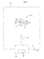
- robotic mower 100 may be powered by battery pack 109 that may be charged periodically at charging station 105.
- Vehicle control unit 101 may control all of the electronic functions of the robotic mower. For example, vehicle control unit 101 may command a pair of traction motors 110, 111 to turn traction drive wheels, blade motor 112 to rotate a cutting blade or blades, battery pack 109, a user interface and various sensors.
- Vehicle control unit 101 may be a printed circuit board assembly that serves as the main control board for the robotic mower.
- the vehicle control unit may interpret and process information from various sensors, and use that information to control and operate the pair of traction motors to drive the robotic mower over a yard in order to maintain the lawn, and to drive the blade motor.
- the vehicle control unit may be connected to a number of sensors including one or more boundary sensors 119, as well as one or more obstacle sensors or accelerometers.
- the vehicle control unit also may communicate with the battery pack in order to monitor the status of the battery pack to maintain a charge for one or more lithium ion batteries in the battery pack.
- the vehicle control unit also may be connected to a user interface module including an LCD display along with several indicator lights and key buttons for operator input.
- the vehicle control unit may include a microcontroller such as an LQFPSTM32F103ZET6 processor from ST Microelectronics.
- the microcontroller may have 512 kB of internal flash memory and 64 kbytes of internal RAM.
- the microcontroller may contain an ARM Cortex M3 core, may run at a maximum core clock frequency, and may use an onboard AtoD converter.
- the vehicle control unit may contain external static random access memory (SRAM) connected to the microcontroller with a 16 bit FSMC bus and have a minimum capacity of 1 Megabit.
- SRAM static random access memory
- the vehicle control unit may include three external EEPROM integrated circuits.
- the EEPROMs may each be 125 kilobyte ICs for a total capacity of 384 kilobytes.
- the EEPROMs may use and SPI interface to the microcontroller and may be used to store configuration data.
- the vehicle control unit may use the microcontroller's internal real time clock module.
- the vehicle control unit may interface and control a blade motor controller to power and control blade motor 112 that drives the cutting blade on the robotic mower.
- blade motor 112 may be a permanent magnet brushless DC motor, such as the EBM Papst 63.20 BLDC motor having a typical output shaft speed range of about 4000 rpm.
- the vehicle control unit may have three inputs which receive signals from hall effect rotor position sensors contained in the blade motor, such as Melexis US 2884 Hall effect sensors.
- the vehicle control unit may sense the speed of the blade motor using feedback from the Hall effect sensors, and may sense the current through the blade motor phases combined.
- the vehicle control unit may be connected to traction motor controllers for each of the left and right traction motors 110, 111.
- Each traction motor may be a permanent magnet brushless DC motor, such as a EBM Papst 42.20 BLDC motor having a typical output shaft speed range of about 2080 rpm.
- the vehicle control unit may have three inputs which receive signals from Hall effect rotor position sensors, such as the Melexis US2884 Hall effect sensor contained in each traction motor.
- the vehicle control unit may sense the speed of each traction motor using a feedback from a hall sensor, and may sense the current through the traction motor phases combined.
- robotic mower 100 may operate in a specified area 102 that is surrounded by main or outer boundary wire 103 which may form a loop positioned at or below the ground or turf surface.
- inner wire 104 may be a shorter loop provided within the area of the main boundary wire where charging station 105 is positioned. The main boundary wire and inner wire may be connected to charging station 105.
- boundary drive circuit 106 may be contained in charging station 105, and may drive signals on the main boundary wire and the inner wire.
- the fundamental frequency of the waveform on the main boundary wire may be about 2 kHz.
- the robotic mower may have a boundary wire sensor 119 to detect the waveform and provide a signal to the vehicle control unit to indicate the distance of the sensor to the main boundary wire.
- the charging station may drive the main boundary wire and inner wire from a single h-bridge device.
- the h-bridge may drive both boundary wires, but only one of the boundary wires at a time, to minimize power requirements and component costs.
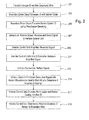
- the boundary driving circuit may transmit a unique ID on the main or outer boundary wire loop ten times per second in block 201.
- the boundary driving circuit may encode the ID with a 4 bit Barker code to improve the signal to noise ratio and reduce susceptibility to noise interference. The resulting 1's and 0's are called chips. A process gain of 6dB may be achieved with four chips, where process gain is the ratio of chip rate to data rate.
- the microprocessor may encode the Barker coded ID using Manchester encoding to ensure there always is a line voltage transition for every bit or chip.
- one or more boundary sensors on the robotic mower may receive the encoded boundary wire magnetic signal, and send the signal to the vehicle control unit.
- the vehicle control unit may amplify the received signal.
- the vehicle control unit's analog to digital converter may sample the amplified signal, preferably at a rate of 200 kHz.
- the vehicle control unit may buffer the sample data for further processing.
- the boundary wire magnetic signal may be very small and similar in amplitude to the background noise if the robotic mower is a significant distance from the main boundary wire loop. This limits the amount of amplification that can be applied to the signal, and it may be difficult to detect the signal using traditional hardware/software methods.
- the vehicle control unit may cross correlate the received signal (at the boundary sensor's present position) with a known waveform (at a known distance to the boundary wire) to identify the start bit in the data buffer and determine if the data is inverted, indicating the sensor is outside the main boundary loop, or normal, indicating the sensor is inside the main boundary loop.
- the peak to peak amplitude of the known waveform may be the theoretical maximum that the boundary sensor and vehicle control unit can receive without distorting the signal.
- Cross correlation is done by converting the known waveform data and the sampled waveform data from the time domain into the frequency domain. This may be accomplished by running a FFT on the data, multiplying the FFT results together, and then running an inverse FFT on the result of that product.
- the vehicle control unit may decode the Manchester and Barker coding, and verify the ID against the identification stored in non-volatile memory.
- the vehicle control unit may determine the relative distance of the sensor from the outer boundary wire.
- the cross correlation function may provide the time lag difference between the known waveform (at a known distance to the boundary wire) and the unknown received sampled waveform (the boundary sensor's distance to the boundary wire).
- the location in time of the maximum peak value of the lag provides the starting location in time of the transmitted data packet located in the sampled waveform data.
- the amplitude of the lag is proportional to the difference between the known waveform's maximum amplitude and the received sample data's maximum amplitude.
- the robotic mower may have one boundary sensor to indicate proximity of the sensor to the wire.
- Fig. 11 is a schematic diagram of an embodiment of the electronic circuit of a boundary sensor on the robotic mower.
- the boundary sensor may include a sense coil L1 and a circuit to amplify and filter the signal from the sense coil before it is applied to the A/D input of the vehicle control unit.
- the battery pack on the robotic mower may have a minimum power input voltage of 20V and a maximum power input voltage of 30v.
- the vehicle control unit may have a +5V power supply to the boundary sensors, and the vehicle control unit may provide a 2.5V reference to each boundary sensor.
- the signal range for each sensor may be 0V to 5.25V.
- sense coil L1 may be an inductor that detects the magnetic field generated by the current flowing in the main or outer boundary wire and/or inner boundary wire.
- sensor coil L1 may be a 100 mH 10% inductor Bournes RL622-104K-RC.
- the maximum peak voltage of the sense coil L1 may be approximately 75mV when the sensor is located six inches from the boundary wire.
- the boundary sensor circuit may include a quad op amp with transimpedance amplifier U1-A, band pass filter U1-B, variable gain amplifier U1-C, and comparator U1-D.
- the quad op amp may be a National Semiconductor LMV64841MX Op Amp (Quad).
- a valid signal from the final stage output of the quad op amp may be greater than about 100mV.
- transimpedance amplifier U1-A may convert the current induced in sense coil L1 into a voltage and amplify that voltage.
- Resistor R1 may convert the output current from sense coil L1 into a voltage.
- the output voltage of the transimpedance amplifier may be equal to the input current multiplied by the feedback resistor R1.
- resistor R1 may be 100k ⁇ .
- Capacitor C1 may provide stability to prevent the transimpedance amplifier from oscillating. Oscillation may be the result of capacitance of the input sensor and the op amp itself.
- C1 may be a 47pF 50V 10% COG ceramic capacitor.
- band pass filter U1-B may provide a second order Sallen-Key high pass filter to cancel noise such as low frequency noise from the traction wheel motors of the robotic mower.
- Capacitors C2 and C3 and resistors R2 and R3 may set the corner or roll off frequency of the filter.
- R2 and R3 may be 1 Meg Ohm 1/16W 1 % resistors, and C2 and C3 may be 100 pF 50 V 5% COG ceramic capacitors.
- the output of the high pass filter may be followed by resistor R4 and capacitor C4, which may perform low pass filtering.
- R4 may be a 10.0k 1/16W 1% resistor
- C4 may be a 47pF 50V 10% COG ceramic capacitor.
- Capacitor C5 may be a decoupling capacitor with a voltage rating high enough for the maximum voltage on the +5V power supply.
- C5 may be a 0.1 ⁇ F 16V 10% X7R MLC capacitor.
- the quad op amp also may include variable gain amplifier U1-C.
- Resistors R5 and R6 may set the gain of the variable gain amplifier, and resistor R6 may provide the negative feedback.
- R5 may be a 10.0k, 1/16W, 1 % resistor, and R6 may be a 100k ⁇ , 1/16W 1% resistor.
- Dual diode D1 may automatically reduce the gain when the received signal strength is higher, such as when the robotic mower is very near the boundary wire. If the output voltage of variable gain amplifier U1-C is too high, one of the pair of diodes D1 may conduct and clamp the voltage across resistor R6, reducing the gain. As the input voltage to the amplifier increases, a point will be reached where the diodes conduct. Beyond this point the feedback from the output to the inverting input will be equal to the voltage across the diode.
- D1 may be an NXP BAV99LT1G high-speed switching dual diode.
- the boundary sensor circuit also may include unity gain buffer U2 A to buffer the output of variable gain amplifier U1-C before connection to the vehicle control unit via a wiring harness.
- unity gain buffer U2-A may be a National Semiconductor LM771 op amp.
- Capacitor C7 may be a bypass capacitor for unity gain buffer U2-A.
- capacitor C7 may be a 0.1 ⁇ F 16V 10% X7R MLC capacitor.
- the boundary sensor circuit may include comparator U1-D which may form a Schmitt trigger comparator circuit to provide an output that indicates whether or not the received signal strength is great enough to be considered a valid signal. If the received signal is greater than the threshold, the output of the comparator will be high.
- Resistors R7 and R8 may form a voltage divider used to set the threshold for a valid signal, indicating a valid signal instead of noise.
- R8 may be a 5.62k, 1/16W 1% resistor
- R7 may be a 200 ⁇ 1/16W1% resistor.
- Resistors R9 and R10 may configure the hysteresis of the comparator, with R10 providing the positive feedback.
- R9 and R10 together set the upper and lower thresholds of the Schmitt trigger comparator.
- R9 may be a 5.62k 1/16W 1% resistor and R10 may be a 1 Meg Ohm 1/16W 1% resistor.
- the robotic mower may have a plurality of boundary sensors 119, and most preferably three boundary sensors mounted at or near the front of the robotic mower and a fourth boundary sensor mounted at or near the back of the robotic mower.
- the vehicle control unit may receive input from each of the boundary sensors regarding strength of the signal from the main boundary wire to indicate proximity of the sensor to the wire.
- the vehicle control unit may use signals from four boundary sensors to determine orientation and heading of the robotic mower with respect to the boundary wire.
- the vehicle control unit may sign the boundary distance signal from each boundary sensor to indicate if the sensor is inside or outside the main boundary wire.
- the vehicle control unit calculates ⁇ 1 as the difference between the distance from the center front sensor to the main boundary wire, compared to the distance from the back sensor to the main boundary wire.
- the vehicle control unit calculates ⁇ 4 as the difference between the left front sensor to the main boundary wire, compared to the distance from the right front sensor to the main boundary wire.
- the vehicle control unit confirms the dimensions between the sensors on the mower based on fixed values stored in memory.
- these dimensions may include L1 between the front center and back sensors, and L2 between the left and right front sensors.
- the vehicle control unit confirms that the values calculated for ⁇ 1 and ⁇ 4 are within the ranges that are possible given the specified dimensions, L1 and L2.
- the vehicle control unit determines which of the four possible heading quadrants the robotic mower is in relative to the main boundary wire. For example, if ⁇ 1 is greater than or equal to 0 and ⁇ 4 is less than or equal to zero, the heading is in quadrant 1.
- the vehicle control unit may flip the angle for readings outside the main boundary wire.
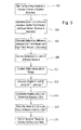
- the vehicle control unit may select the type of area coverage used by the robotic mower for mowing within the main boundary wire. Using the steps described below in the block diagram of Fig. 4 , the vehicle control unit may command the robotic mower to switch from one type of area coverage to another without operator intervention and without discontinuing mowing.
- the vehicle control unit may select the type of area coverage based on input from one or more boundary sensors 119 regarding distance of the robotic mower to the main boundary wire, current draw of electric blade motor 112 that rotates one or more cutting blades, and the type of area coverage used during a specified preceding time period which may be stored in the vehicle control unit memory.
- the robotic mower in block 400 the robotic mower may be activated to start area coverage, such as by an operator or by an internal or external timer.
- the vehicle control unit then may run the routine described in the block diagram about every 40 milliseconds.
- the vehicle control unit may determine if the robotic mower is in the charging station, preferably by checking if the voltage on the charger contacts is within a specified range. If the robotic mower is in the charging station, in block 402 the vehicle control unit may command the traction wheel motors to leave the charging station by rotating in reverse for a specified distance or duration to back up the robotic mower out and away from the charging station, then turn the robotic mower around.
- the vehicle control unit may determine how much each wheel motor has rotated based on pulse feedback from the Hall effect sensor in each motor. If the vehicle control unit determines the robotic mower is not in the charging station, in block 403 the vehicle control unit may determine if the leave dock instruction is still active. If the leave dock instruction is still active, in block 404 the vehicle control unit may command the wheel motors of the robotic mower to continue executing the leave dock instruction.
- the vehicle control unit may determine if a bump is detected, indicating the robotic mower has contacted an obstacle.
- Bump detection may be provided to the vehicle control unit by one or more accelerometers attached to the chassis and/or top cover of the robotic mower.
- the accelerometer may be a three axis accelerometer such as the ST LIS302DL which also may be used to sense lifting and orientation, and may communicate to the microcontroller with a SPI bus at the voltage logic level of the microcontroller. If the accelerometer indicates an obstacle is bumped, in block 406 the vehicle control unit may command both traction motors to reverse direction for a specified distance or duration and then turn the robotic mower around.
- the vehicle control unit may determine if a specified coverage such as boundary coverage was executed within a specified preceding time period such as seven days.
- the vehicle control unit memory may store data on the type of coverage executed for a specified preceding time period. If boundary coverage was not executed during the specified preceding time period, in block 408 the vehicle control unit may command the traction motors to execute boundary coverage. Preferred boundary coverages are described below.
- the vehicle control unit may determine if the robotic mower is closer to the boundary or perimeter wire than a specified distance, using input from one or more boundary sensors 119. If the robotic mower is closer than the specified distance, in block 410 the vehicle control unit may command the traction motors to reverse direction for a specified duration and then turn the robotic mower around.
- the vehicle control unit may determine if the wheel motors are currently executing the reverse and turn around function. If the motors are still in reverse for the prespecified distance or duration, or have not finished turning the robotic mower around, in block 412 the vehicle control unit may command both traction wheel motors to continue the reverse and turn around functions.
- the vehicle control unit may determine if the blade load is greater than a first predetermined specified value X which indicates uncut grass. Higher current means higher blade load and torque, indicating longer, uncut grass. Lower current, lower blade load and torque, indicates shorter, cut grass. If the blade load is greater than the first value, in block 414 the vehicle control unit may command the traction wheel motors to execute local area coverage. A preferred local area coverage is described below.
- the vehicle control unit commands the traction wheel motors traction motors to execute wide area coverage.
- a preferred wide area coverage is described below.
- the vehicle control unit may execute wide area coverage by commanding the left and right wheel motors to drive the robotic mower in a straight line until an obstacle or boundary wire is encountered.
- the vehicle control unit may command the wheel motors to reverse and back up the mower for a prespecified distance and then turn the robotic mower around, preferably less than 180 degrees, to follow a path that diverges from the preceding forward path.
- the vehicle control unit may specify and execute other methods of wide area coverage, including but not limited to traveling in arcs instead of straight lines.
- wide area coverage may begin executing in block 500.
- the vehicle control unit may set the forward ground speed of the traction wheel motors at a nominal speed, and to maintain the same yaw or steering angle (i.e., 0 degrees for a straight path) so that the robotic mower travels in a straight line.
- the vehicle control unit determines if the robotic mower has bumped an obstacle, as indicated by one or more accelerometers, for example. If the robotic mower has detected an obstacle, in block 508 the vehicle control unit may command both traction wheel motors to rotate in reverse to back up at a reduced ground speed, and to maintain the same yaw angle. If the robotic mower has not bumped an obstacle in block 504, the vehicle control unit may determine if one or more boundary sensors indicate the mower is closer to the main boundary wire than a prespecified threshold distance. If one or more boundary sensors indicate the robotic mower is not close to the main boundary wire, the vehicle control unit commands the left and right wheel motors to continue rotating forward as indicated in block 502.
- the vehicle control unit may command the wheel motors to rotate in reverse at a reduced ground speed, and to maintain the same yaw angle.
- the vehicle control unit may determine if the traction wheel motors have rotated in reverse a prespecified or threshold time or distance. If the traction wheel motors have not rotated the prespecified time or distance in reverse, the vehicle control unit may command the motors to continue in reverse as indicated in block 510.
- the vehicle control unit may set a target yaw angle at a prespecified angle, preferably less than 180 degrees, and command the left and right wheel motors to turn the robotic mower around at a ground speed of zero.
- the vehicle control unit determines the turn error from the target yaw angle.
- the vehicle control unit may command the traction wheel motors to rotate in forward again at a nominal speed and maintain the same yaw angle (i.e., 0 degrees), as specified in block 502. If the turn angle has not reached the target yaw angle yet, the vehicle control unit will command the traction wheel motors to continue turning the robotic mower around, and then calculate the turn error again in block 514.
- local area coverage may be a path that spirals outwardly, either clockwise or counterclockwise, from the robotic mower's initial position.
- Alternatives for local area coverage may include other patterns starting from an initial position of the robotic mower.
- the vehicle control unit begins executing local area coverage.
- the vehicle control unit may determine the radius from the spiral center, where local area coverage began, to the current location of the robotic mower.
- the radius value is zero, and may be incremented based on the difference in radius between sequential passes of the robotic mower around the spiral.
- the radius value is a function of how many degrees the robotic mower has traveled around the spiral, and the spacing of the spiral based on the robotic mower's effective cutting width.
- the vehicle control unit may determine if the radius is less than a prespecified minimum value. If it is less than the minimum value, in block 608 the vehicle control unit may command the traction wheel motors to rotate at a minimum forward ground speed. In block 610, the vehicle control unit may determine if the radius is less than an intermediate value. If the radius is less than the intermediate value, in block 612 the vehicle control unit may command the traction wheel motors to rotate at a reduced forward ground speed, which may be greater than the minimum speed. In block 614, the vehicle control unit may command the traction wheel motors to rotate at a nominal forward ground speed, which may be higher than the reduced speed, if the radius is at least the intermediate value.
- the vehicle control unit determines the desired change in yaw angle for the sample, which may be a function of the time period between function calls, the ground speed, and the radius.
- the vehicle control unit may add the desired change in yaw angle to the spiral total.
- the vehicle control unit may determine the desired yaw angle for the robotic mower, which may be based on the current yaw angle plus the desired change in yaw angle.
- the robotic mower may execute boundary coverage, or return to the charging station, on a path along or parallel to the boundary wire using the system described in the block diagram of Fig. 7 .
- the vehicle control unit may use this system based on input from one boundary sensor on the robotic mower regarding strength of the signal from the main boundary wire to indicate proximity of the sensor to the wire.
- the vehicle control unit may use input from the boundary sensor to direct the traction wheel motors to follow a path along or at a specified distance parallel to the boundary wire.
- the vehicle control unit may command the left and right traction motors to start rotating in forward on a path at a specified distance parallel to the boundary wire.
- the vehicle control unit compares the input from the boundary sensor to the specified distance, to decide if the robotic mower is too close or too far from the boundary wire. If the boundary sensor indicates it is within the specified distance to the boundary wire, in block 702 the vehicle control unit commands the left and right wheel traction drive motors to continue rotating straight ahead.
- the vehicle control unit determines if the error or deviation from the specified distance has decreased, by comparing the boundary sensor input to one or more previous boundary sensor inputs, preferably spanning a time period of at least about one second. If the error has not decreased, in block 704 the vehicle control unit commands the left and right wheel motors to turn the vehicle at a larger acute angle (such as 30 degrees) away from or back toward the boundary wire, depending on whether the robotic mower is too close or too far from the boundary wire.
- a larger acute angle such as 30 degrees
- the vehicle control unit commands the left and right wheel motors to turn the vehicle at a reduced acute angle (such as 4 degrees) away from or back toward the boundary wire, depending on whether the boundary sensor is too close or too far from the boundary wire.
- the vehicle control unit may command the robotic mower to execute boundary coverage using one or more patterns along the boundary or perimeter wire.
- This boundary coverage may use a pattern that minimizes turf damage or rutting along the boundary due to repetitive wear from the robotic mower's traction drive wheels and caster wheels.
- boundary coverage may use variable traffic patterns such as a zig-zag pattern to shift the wheel tracks each time the robotic mower executes boundary coverage along the boundary or perimeter wire.
- Other alternatives also may be specified by the robotic mower controller for boundary coverage, including but not limited to sine or square wave patterns along the boundary or perimeter wire.
- the vehicle control unit may use information received from one or more boundary sensors regarding the distance of the robotic mower to the boundary wire, to alternate the robotic mower's path between driving toward and away from the boundary wire at a specified angle. For example, as shown in Fig. 8 , the vehicle control unit may execute boundary coverage beginning in block 800.
- the vehicle control unit may set a flag as a function of the distance between the boundary sensor and the boundary wire. For example, the flag may be set at 0 if the boundary sensor indicates it is within a threshold distance to the boundary wire, or 1 if it is further than the threshold distance.
- the vehicle control unit may specify the yaw angle of the robotic mower in relation to the main boundary wire at either plus 45 degrees or minus 45 degrees, depending on the flag setting.
- the vehicle control unit may command the left and right wheel motors to move the robotic mower forward at a reduced forward ground speed.
- the vehicle control unit may determine if the robotic mower is within a minimum distance to the boundary wire. If the robotic mower is within the minimum distance, the vehicle control unit may reset the flag in block 802. If not, the vehicle control unit may determine if the robotic mower is farther than a maximum distance from the boundary wire. If the robotic mower is further than the maximum distance, the vehicle control unit may reset the flag in block 802. Otherwise, the vehicle control unit may command the wheel motors to continue rotating forward at the reduced speed, as shown in block 806. Thus, the vehicle control unit may command the traction motors to toggle back and forth between plus 45 and minus 45 degrees as a function of the robotic mower's distance to the perimeter wire.
- the robotic mower's path along the boundary wire may change or shift each time it executes boundary coverage.
- the shift ensures that the same turf is not repeatedly contacted and compacted by the robotic mower's wheels.
- the shift may occur because the robotic mower will often have a different starting position each time it starts executing boundary coverage.
- a shift may result from changing the boundary coverage pattern by including variables in the vehicle control unit logic such as the minimum and maximum distances used to toggle the desired orientation, or using a different angle other than 45 degrees.
- the vehicle control unit may vary the distance of the robotic mower's path when the robotic mower executes home finding to return to the charging station.
- the vehicle control unit may specify a return path that is offset from the main boundary wire, and varies over a range of available paths between a minimum offset and a maximum offset.
- the minimum and maximum allowable offset from the main boundary wire may be preselected or constant. Alternatively, the offset may be incremented or reduced each time the robotic mower returns to the charging station.
- the vehicle control unit may execute home finding in block 900.
- the vehicle control unit may find the main boundary wire using one or more boundary sensors.
- the vehicle control unit may select a random variable.
- the vehicle control unit may increment a variable from the last execution of the home finding task.
- the vehicle control unit may determine the desired offset from the boundary wire based on the random or incremented variable.
- the vehicle control unit may command the wheel motors to rotate at the nominal forward speed, and at a yaw angle needed to maintain the desired offset.
- the vehicle control unit determines if the inner loop wire is detected by the boundary sensors.
- the vehicle control unit may continue commanding the wheel motors to rotate forward as shown in block 910. If the inner loop wire is detected, the vehicle control unit commands the wheel motors to reduce speed, and sets the yaw angle to orient the robotic mower to enter the charging station.
- the vehicle control unit memory may record and store the time when an obstacle or boundary wire has been last detected, and may determine the robotic mower is stuck if a prespecified amount of time elapses before the robotic mower encounters an obstacle or boundary wire again.
- an accelerometer or similar device may be used to detect obstacles, and one or more boundary sensors may be used to detected the boundary wire.
- the timer duration may be prespecified by the operator or as a function of the size of the area to be mowed, obstacle density, vehicle speed and navigation rules. Additionally, the timer duration may be a function of the type of area coverage being executed by the robotic mower.
- the timer duration may be the product of the expected maximum distance between obstacles or boundaries, and the robotic mower's expected travel speed.
- the timer duration may be relatively short during boundary coverage because the vehicle control unit expects to encounter the boundary again after traveling only a short distance.
- the timer duration for wide area coverage may be determined from the maximum span between opposite boundaries if the robotic mower travels in a straight line.
- the vehicle control unit may execute stuck detection in block 1000.
- the vehicle control unit may set a timer based on maximum distance and mower speed.
- the vehicle control unit may determine if an obstacle or boundary wire is detected by an accelerometer or boundary sensor. If an obstacle or boundary wire is detected, in block 1006 the vehicle control unit may command the robotic mower to reverse and turn around, and then reset the timer again in block 1002. If an obstacle or boundary wire is not detected, in block 1008 the vehicle control unit may determine if the timer exceeds a specified maximum time. If the timer does not exceed the specified maximum, the vehicle control unit may resume checking if an obstacle or boundary wire is detected in block 1004. If the specified maximum time is exceeded, in block 1010 the vehicle control unit may execute a stuck vehicle task to safely move or stop the robotic mower.
Applications Claiming Priority (2)
| Application Number | Priority Date | Filing Date | Title |
|---|---|---|---|
| US12/845,326 US8392044B2 (en) | 2010-07-28 | 2010-07-28 | Robotic mower boundary sensing system |
| EP11174304.3A EP2412221B1 (fr) | 2010-07-28 | 2011-07-18 | Système de détection de limite de tondeuse mécanique et tondeuse mécanique |
Related Parent Applications (3)
| Application Number | Title | Priority Date | Filing Date |
|---|---|---|---|
| EP11174304.3 Division | 2011-07-18 | ||
| EP11174304.3A Division EP2412221B1 (fr) | 2010-07-28 | 2011-07-18 | Système de détection de limite de tondeuse mécanique et tondeuse mécanique |
| EP11174304.3A Division-Into EP2412221B1 (fr) | 2010-07-28 | 2011-07-18 | Système de détection de limite de tondeuse mécanique et tondeuse mécanique |
Publications (2)
| Publication Number | Publication Date |
|---|---|
| EP2572567A1 true EP2572567A1 (fr) | 2013-03-27 |
| EP2572567B1 EP2572567B1 (fr) | 2016-09-14 |
Family
ID=44508806
Family Applications (3)
| Application Number | Title | Priority Date | Filing Date |
|---|---|---|---|
| EP12198863.8A Active EP2572567B1 (fr) | 2010-07-28 | 2011-07-18 | Tondeuse robotisée avec une système de détection de limite |
| EP11174304.3A Active EP2412221B1 (fr) | 2010-07-28 | 2011-07-18 | Système de détection de limite de tondeuse mécanique et tondeuse mécanique |
| EP12198850.5A Active EP2572566B1 (fr) | 2010-07-28 | 2011-07-18 | Tondeuse robotisé avec une système de détection de limite |
Family Applications After (2)
| Application Number | Title | Priority Date | Filing Date |
|---|---|---|---|
| EP11174304.3A Active EP2412221B1 (fr) | 2010-07-28 | 2011-07-18 | Système de détection de limite de tondeuse mécanique et tondeuse mécanique |
| EP12198850.5A Active EP2572566B1 (fr) | 2010-07-28 | 2011-07-18 | Tondeuse robotisé avec une système de détection de limite |
Country Status (2)
| Country | Link |
|---|---|
| US (3) | US8392044B2 (fr) |
| EP (3) | EP2572567B1 (fr) |
Families Citing this family (51)
| Publication number | Priority date | Publication date | Assignee | Title |
|---|---|---|---|---|
| US8093831B2 (en) * | 2009-08-20 | 2012-01-10 | Qi Deng | Voltage converter with first push |
| US8392044B2 (en) * | 2010-07-28 | 2013-03-05 | Deere & Company | Robotic mower boundary sensing system |
| US9807925B2 (en) * | 2010-07-28 | 2017-11-07 | Deere & Company | Robotic mower area coverage system |
| JP5420510B2 (ja) * | 2010-09-30 | 2014-02-19 | 本田技研工業株式会社 | 自律走行作業車の制御装置 |
| JP5664769B2 (ja) * | 2011-04-22 | 2015-02-04 | トヨタ自動車株式会社 | 車両および車両用制御方法 |
| JP5836151B2 (ja) * | 2012-02-10 | 2015-12-24 | 本田技研工業株式会社 | 無人走行作業車用エリアワイヤの配置構造およびその制御装置 |
| US9072218B2 (en) | 2012-07-09 | 2015-07-07 | Deere & Company | Boundary sensor assembly for a robotic lawn mower, robotic lawn mower and robotic lawn mower system |
| US9026299B2 (en) | 2012-07-09 | 2015-05-05 | Deere & Company | Navigation system and method for autonomous mower |
| EP3373097A1 (fr) * | 2012-08-14 | 2018-09-12 | Husqvarna AB | Tondeuse robotique comportant un système de détection d'objet |
| EP2939508B1 (fr) | 2012-12-28 | 2021-05-19 | Positec Power Tools (Suzhou) Co., Ltd | Système de tondeuse automatique |
| WO2014129941A1 (fr) * | 2013-02-20 | 2014-08-28 | Husqvarna Ab | Outil de travail robotique configuré pour mieux tourner dans une pente, système d'outil de travail robotique et procédé d'utilisation de l'outil de travail robotique |
| US9713303B2 (en) | 2013-02-21 | 2017-07-25 | Husqvarna Ab | Robotic working tool |
| CA2906934C (fr) | 2013-03-15 | 2021-11-16 | Mtd Products Inc | Systeme de travail mobile autonome comprenant une station de base a reflectivite variable |
| CN104111651A (zh) * | 2013-04-22 | 2014-10-22 | 苏州宝时得电动工具有限公司 | 自动行走设备及其向停靠站回归的方法 |
| US9072219B2 (en) * | 2013-06-20 | 2015-07-07 | Deere & Company | Robotic mower navigation system |
| ITMI20131252A1 (it) * | 2013-07-25 | 2015-01-26 | Fabrizio Bernini | Apparecchiatura di lavorazione di un¿area limitata |
| CN104635728A (zh) * | 2013-11-14 | 2015-05-20 | 沈阳新松机器人自动化股份有限公司 | 机器人自主充电系统和方法 |
| EP3102021B1 (fr) | 2014-02-03 | 2020-03-11 | Husqvarna AB | Ressort de plaque conçu pour maintenir un outil, outil, support d'outil, outil de travail robotique et système d'outil de travail robotique |
| DE102014212435A1 (de) * | 2014-06-27 | 2015-12-31 | Robert Bosch Gmbh | Signalverarbeitungsvorrichtung für einen autonomen Serviceroboter |
| US10609862B2 (en) | 2014-09-23 | 2020-04-07 | Positec Technology (China) Co., Ltd. | Self-moving robot |
| US20160128275A1 (en) * | 2014-11-12 | 2016-05-12 | Deere & Company | Robotic mower contact detection system |
| EP3230815B1 (fr) * | 2014-12-11 | 2020-05-06 | Husqvarna AB | Navigation améliorée pour outil de travail robotique |
| US10379172B2 (en) * | 2015-06-05 | 2019-08-13 | Irobot Corporation | Magnetic field localization and navigation |
| US9903947B2 (en) * | 2015-08-10 | 2018-02-27 | Deere & Company | Boundary signal detection |
| EP3156873B2 (fr) | 2015-10-15 | 2023-04-05 | Honda Research Institute Europe GmbH | Véhicule autonome avec localisation simultanée améliorée et fonction de cartographie |
| EP3452880A1 (fr) | 2016-05-06 | 2019-03-13 | MTD Products Inc. | Système et procédé de navigation de tondeuse autonome |
| US11172608B2 (en) | 2016-06-30 | 2021-11-16 | Tti (Macao Commercial Offshore) Limited | Autonomous lawn mower and a system for navigating thereof |
| WO2018000922A1 (fr) | 2016-06-30 | 2018-01-04 | Tti (Macao Commercial Offshore) Limited | Tondeuse à gazon autonome et système de navigation associé |
| US10405440B2 (en) | 2017-04-10 | 2019-09-03 | Romello Burdoucci | System and method for interactive protection of a mobile electronic device |
| AU2017367062A1 (en) * | 2016-11-29 | 2019-07-18 | Briggs & Stratton, Llc | Robotic lawn mower including removable rechargeable battery module |
| SE540605C2 (en) * | 2017-03-02 | 2018-10-02 | Husqvarna Ab | Improved reduction of wheel tracks for robotic lawnmower |
| JP2020106872A (ja) * | 2017-04-21 | 2020-07-09 | パナソニックIpマネジメント株式会社 | 移動装置、物体検出方法及びプログラム |
| SE543987C2 (en) * | 2017-04-25 | 2021-10-19 | Husqvarna Ab | Improved reception of frequency spectra on the receiver side |
| SE1750499A1 (en) * | 2017-04-25 | 2018-10-02 | Husqvarna Ab | Compensating for stray capacitances for a robotic lawnmower |
| EP3412134B1 (fr) * | 2017-06-09 | 2020-08-19 | Andreas Stihl AG & Co. KG | Système de traitement de sol comprenant un câble périphérique continu |
| US20190054621A1 (en) * | 2017-08-16 | 2019-02-21 | Franklin Robotics, Inc. | Inertial Collision Detection Method For Outdoor Robots |
| US10767383B2 (en) * | 2017-11-07 | 2020-09-08 | Robin Technologies, Inc. | Ground wire guidance system for robotic vehicle with doorway access |
| EP3595428B1 (fr) * | 2017-12-30 | 2021-10-20 | Globe (Jiangsu) Co., Ltd. | Système et procédé de commande d'une tondeuse à gazon autopropulsée |
| US11197414B2 (en) | 2018-01-26 | 2021-12-14 | Briggs & Stratton, Llc | Systems and devices for autonomous lawn care |
| EP3595432B1 (fr) * | 2018-02-07 | 2021-08-18 | Globe (Jiangsu) Co., Ltd. | Système et procédé d'accueil d'un robot tondeuse |
| US20210294348A1 (en) * | 2018-08-08 | 2021-09-23 | Positec Power Tools (Suzhou) Co., Ltd. | Self-moving device, automatic working system, and control method therefor |
| WO2020123385A1 (fr) | 2018-12-11 | 2020-06-18 | Irobot Corporation | Systèmes de navigation magnétique pour robots mobiles autonomes |
| EP3683643B1 (fr) * | 2019-01-15 | 2022-06-15 | Honda Research Institute Europe GmbH | Système comprenant un dispositif mobile autonome et une station de base communiquant par l'intermédiaire d'un câble périphérique |
| CN112119742B (zh) * | 2019-06-25 | 2023-10-10 | 宝时得科技(中国)有限公司 | 智能割草机及智能割草机的自动控制方法 |
| US11483968B2 (en) | 2019-08-05 | 2022-11-01 | Firefly Automatix, Inc. | Dynamically adjusting the cutting height of a mower deck based on a mower's location |
| US11469604B2 (en) | 2019-09-13 | 2022-10-11 | Echo Incorporated | System for facilitating connection between a charging station and a rechargeable power supply on an operating unit |
| CN112764419B (zh) * | 2020-12-25 | 2024-03-05 | 格力博(江苏)股份有限公司 | 自动割草机的路径规划方法、系统、设备及自动割草机 |
| CN111949023B (zh) * | 2020-07-31 | 2023-04-18 | 南京苏美达智能技术有限公司 | 一种自行走设备的边界探测方法和自行走设备 |
| CN115373375B (zh) * | 2021-05-18 | 2023-08-18 | 未岚大陆(北京)科技有限公司 | 机器人的返回充电桩的方法、装置、机器人及存储介质 |
| CN115868303A (zh) * | 2021-09-29 | 2023-03-31 | 创科无线普通合伙 | 机器人园林工具系统及用于机器人园林工具的方法 |
| WO2024078482A1 (fr) * | 2022-10-13 | 2024-04-18 | 浙江白马科技有限公司 | Circuit et procédé de commande de signal, et appareil de génération, station d'accueil, système de fonctionnement autonome et support de stockage |
Citations (6)
| Publication number | Priority date | Publication date | Assignee | Title |
|---|---|---|---|---|
| WO1999059042A1 (fr) * | 1998-05-11 | 1999-11-18 | Friendly Machines Ltd. | Couverture de zone au moyen d'un robot autonome |
| WO2003104909A1 (fr) * | 2002-06-07 | 2003-12-18 | Aktiebolaget Electrolux | Systeme de commande electronique |
| EP1906205A1 (fr) * | 2006-09-29 | 2008-04-02 | F. Robotics Acquisitions Ltd. | Procédé et système de détermination de l'emplacement d'un véhicule |
| EP1933467A2 (fr) * | 2006-12-06 | 2008-06-18 | F. Robotics Aquisitions Ltd. | Robot autonome |
| EP2082638A1 (fr) * | 2008-01-23 | 2009-07-29 | Fabrizio Bernini | Tondeuse à gazon |
| EP2413214A1 (fr) * | 2010-07-28 | 2012-02-01 | Deere & Company | Système de suivi de zone limite de tonte pour une tondeuse mécanique et tondeuse mécanique |
Family Cites Families (8)
| Publication number | Priority date | Publication date | Assignee | Title |
|---|---|---|---|---|
| US2884A (en) | 1842-12-12 | Washiitg-m achine | ||
| SE510524C2 (sv) * | 1997-09-19 | 1999-05-31 | Electrolux Ab | Elektroniskt avgränsningssystem |
| SE511254C2 (sv) | 1998-01-08 | 1999-09-06 | Electrolux Ab | Elektroniskt söksystem för arbetsredskap |
| SE0201739D0 (sv) | 2002-06-07 | 2002-06-07 | Electrolux Ab | Elektroniskt avgränsningssystem |
| ITFI20040151A1 (it) | 2004-07-02 | 2004-10-02 | Zucchetti Ct Sistemi S P A | Sistema di rilevamento perimetrale |
| WO2009076156A2 (fr) * | 2007-12-07 | 2009-06-18 | Christian Steele | Système et procédé de détermination de position |
| DE102009001900A1 (de) * | 2008-10-20 | 2010-04-22 | Robert Bosch Gmbh | Verfahren und System zur Arbeitsbereichserkennung eines mobilen Arbeitsgerätes |
| US8392044B2 (en) * | 2010-07-28 | 2013-03-05 | Deere & Company | Robotic mower boundary sensing system |
-
2010
- 2010-07-28 US US12/845,326 patent/US8392044B2/en active Active
-
2011
- 2011-07-18 EP EP12198863.8A patent/EP2572567B1/fr active Active
- 2011-07-18 EP EP11174304.3A patent/EP2412221B1/fr active Active
- 2011-07-18 EP EP12198850.5A patent/EP2572566B1/fr active Active
-
2012
- 2012-12-21 US US13/724,159 patent/US8706339B2/en active Active
- 2012-12-21 US US13/724,112 patent/US8725316B2/en active Active
Patent Citations (6)
| Publication number | Priority date | Publication date | Assignee | Title |
|---|---|---|---|---|
| WO1999059042A1 (fr) * | 1998-05-11 | 1999-11-18 | Friendly Machines Ltd. | Couverture de zone au moyen d'un robot autonome |
| WO2003104909A1 (fr) * | 2002-06-07 | 2003-12-18 | Aktiebolaget Electrolux | Systeme de commande electronique |
| EP1906205A1 (fr) * | 2006-09-29 | 2008-04-02 | F. Robotics Acquisitions Ltd. | Procédé et système de détermination de l'emplacement d'un véhicule |
| EP1933467A2 (fr) * | 2006-12-06 | 2008-06-18 | F. Robotics Aquisitions Ltd. | Robot autonome |
| EP2082638A1 (fr) * | 2008-01-23 | 2009-07-29 | Fabrizio Bernini | Tondeuse à gazon |
| EP2413214A1 (fr) * | 2010-07-28 | 2012-02-01 | Deere & Company | Système de suivi de zone limite de tonte pour une tondeuse mécanique et tondeuse mécanique |
Also Published As
| Publication number | Publication date |
|---|---|
| US8706339B2 (en) | 2014-04-22 |
| EP2572567B1 (fr) | 2016-09-14 |
| EP2572566B1 (fr) | 2016-05-04 |
| EP2412221A2 (fr) | 2012-02-01 |
| US8725316B2 (en) | 2014-05-13 |
| US20120029754A1 (en) | 2012-02-02 |
| US20130211625A1 (en) | 2013-08-15 |
| EP2412221A3 (fr) | 2013-03-20 |
| EP2412221B1 (fr) | 2016-08-24 |
| US8392044B2 (en) | 2013-03-05 |
| EP2572566A1 (fr) | 2013-03-27 |
| US20130211704A1 (en) | 2013-08-15 |
Similar Documents
| Publication | Publication Date | Title |
|---|---|---|
| EP2572567B1 (fr) | Tondeuse robotisée avec une système de détection de limite | |
| EP2413215B1 (fr) | Tondeuse robotique avec un système pour retourner à la station de base | |
| EP2413214B1 (fr) | Système de suivi de zone limite de tonte pour une tondeuse robotisée | |
| EP2412223B1 (fr) | Système de couverture de zone de tondeuse mécanique et tondeuse mécanique | |
| EP2412222A2 (fr) | Système de détection bloquée de tondeuse mécanique et tondeuse mécanique | |
| EP2551739B1 (fr) | Système de point de lancement de tondeuse mécanique | |
| US9788481B2 (en) | Robotic mower navigation system | |
| US9072219B2 (en) | Robotic mower navigation system | |
| US20230071262A1 (en) | Robotic mower and method, system and device of path planning thereof | |
| CN113766825A (zh) | 节能草坪养护车辆 | |
| CN214151499U (zh) | 自动割草机的路径规划设备 | |
| US20240122100A1 (en) | Transversal Method and System, Robot and Readable Storage Medium | |
| US20230085538A1 (en) | Robotic mower and method, system and device of path planning thereof | |
| CN112799395A (zh) | 自动割草机的路径规划方法、系统、设备及自动割草机 | |
| CN114167852A (zh) | 机器人系统及基于磁场信号的机器人避障方法 | |
| CN115373375A (zh) | 机器人的返回充电桩的方法、装置、机器人及存储介质 |
Legal Events
| Date | Code | Title | Description |
|---|---|---|---|
| PUAI | Public reference made under article 153(3) epc to a published international application that has entered the european phase |
Free format text: ORIGINAL CODE: 0009012 |
|
| AC | Divisional application: reference to earlier application |
Ref document number: 2412221 Country of ref document: EP Kind code of ref document: P |
|
| AK | Designated contracting states |
Kind code of ref document: A1 Designated state(s): AL AT BE BG CH CY CZ DE DK EE ES FI FR GB GR HR HU IE IS IT LI LT LU LV MC MK MT NL NO PL PT RO RS SE SI SK SM TR |
|
| AX | Request for extension of the european patent |
Extension state: BA ME |
|
| 17P | Request for examination filed |
Effective date: 20130927 |
|
| RBV | Designated contracting states (corrected) |
Designated state(s): AL AT BE BG CH CY CZ DE DK EE ES FI FR GB GR HR HU IE IS IT LI LT LU LV MC MK MT NL NO PL PT RO RS SE SI SK SM TR |
|
| 17Q | First examination report despatched |
Effective date: 20131107 |
|
| GRAP | Despatch of communication of intention to grant a patent |
Free format text: ORIGINAL CODE: EPIDOSNIGR1 |
|
| INTG | Intention to grant announced |
Effective date: 20160405 |
|
| GRAS | Grant fee paid |
Free format text: ORIGINAL CODE: EPIDOSNIGR3 |
|
| GRAA | (expected) grant |
Free format text: ORIGINAL CODE: 0009210 |
|
| AC | Divisional application: reference to earlier application |
Ref document number: 2412221 Country of ref document: EP Kind code of ref document: P |
|
| AK | Designated contracting states |
Kind code of ref document: B1 Designated state(s): AL AT BE BG CH CY CZ DE DK EE ES FI FR GB GR HR HU IE IS IT LI LT LU LV MC MK MT NL NO PL PT RO RS SE SI SK SM TR |
|
| REG | Reference to a national code |
Ref country code: GB Ref legal event code: FG4D |
|
| REG | Reference to a national code |
Ref country code: CH Ref legal event code: EP |
|
| REG | Reference to a national code |
Ref country code: IE Ref legal event code: FG4D |
|
| REG | Reference to a national code |
Ref country code: AT Ref legal event code: REF Ref document number: 827853 Country of ref document: AT Kind code of ref document: T Effective date: 20161015 |
|
| REG | Reference to a national code |
Ref country code: DE Ref legal event code: R096 Ref document number: 602011030467 Country of ref document: DE |
|
| REG | Reference to a national code |
Ref country code: LT Ref legal event code: MG4D |
|
| REG | Reference to a national code |
Ref country code: NL Ref legal event code: MP Effective date: 20160914 |
|
| PG25 | Lapsed in a contracting state [announced via postgrant information from national office to epo] |
Ref country code: RS Free format text: LAPSE BECAUSE OF FAILURE TO SUBMIT A TRANSLATION OF THE DESCRIPTION OR TO PAY THE FEE WITHIN THE PRESCRIBED TIME-LIMIT Effective date: 20160914 Ref country code: LT Free format text: LAPSE BECAUSE OF FAILURE TO SUBMIT A TRANSLATION OF THE DESCRIPTION OR TO PAY THE FEE WITHIN THE PRESCRIBED TIME-LIMIT Effective date: 20160914 Ref country code: FI Free format text: LAPSE BECAUSE OF FAILURE TO SUBMIT A TRANSLATION OF THE DESCRIPTION OR TO PAY THE FEE WITHIN THE PRESCRIBED TIME-LIMIT Effective date: 20160914 Ref country code: HR Free format text: LAPSE BECAUSE OF FAILURE TO SUBMIT A TRANSLATION OF THE DESCRIPTION OR TO PAY THE FEE WITHIN THE PRESCRIBED TIME-LIMIT Effective date: 20160914 Ref country code: NO Free format text: LAPSE BECAUSE OF FAILURE TO SUBMIT A TRANSLATION OF THE DESCRIPTION OR TO PAY THE FEE WITHIN THE PRESCRIBED TIME-LIMIT Effective date: 20161214 |
|
| REG | Reference to a national code |
Ref country code: AT Ref legal event code: MK05 Ref document number: 827853 Country of ref document: AT Kind code of ref document: T Effective date: 20160914 |
|
| PG25 | Lapsed in a contracting state [announced via postgrant information from national office to epo] |
Ref country code: SE Free format text: LAPSE BECAUSE OF FAILURE TO SUBMIT A TRANSLATION OF THE DESCRIPTION OR TO PAY THE FEE WITHIN THE PRESCRIBED TIME-LIMIT Effective date: 20160914 Ref country code: GR Free format text: LAPSE BECAUSE OF FAILURE TO SUBMIT A TRANSLATION OF THE DESCRIPTION OR TO PAY THE FEE WITHIN THE PRESCRIBED TIME-LIMIT Effective date: 20161215 Ref country code: NL Free format text: LAPSE BECAUSE OF FAILURE TO SUBMIT A TRANSLATION OF THE DESCRIPTION OR TO PAY THE FEE WITHIN THE PRESCRIBED TIME-LIMIT Effective date: 20160914 Ref country code: LV Free format text: LAPSE BECAUSE OF FAILURE TO SUBMIT A TRANSLATION OF THE DESCRIPTION OR TO PAY THE FEE WITHIN THE PRESCRIBED TIME-LIMIT Effective date: 20160914 |
|
| PG25 | Lapsed in a contracting state [announced via postgrant information from national office to epo] |
Ref country code: EE Free format text: LAPSE BECAUSE OF FAILURE TO SUBMIT A TRANSLATION OF THE DESCRIPTION OR TO PAY THE FEE WITHIN THE PRESCRIBED TIME-LIMIT Effective date: 20160914 Ref country code: RO Free format text: LAPSE BECAUSE OF FAILURE TO SUBMIT A TRANSLATION OF THE DESCRIPTION OR TO PAY THE FEE WITHIN THE PRESCRIBED TIME-LIMIT Effective date: 20160914 |
|
| PG25 | Lapsed in a contracting state [announced via postgrant information from national office to epo] |
Ref country code: CZ Free format text: LAPSE BECAUSE OF FAILURE TO SUBMIT A TRANSLATION OF THE DESCRIPTION OR TO PAY THE FEE WITHIN THE PRESCRIBED TIME-LIMIT Effective date: 20160914 Ref country code: BE Free format text: LAPSE BECAUSE OF FAILURE TO SUBMIT A TRANSLATION OF THE DESCRIPTION OR TO PAY THE FEE WITHIN THE PRESCRIBED TIME-LIMIT Effective date: 20160914 Ref country code: PL Free format text: LAPSE BECAUSE OF FAILURE TO SUBMIT A TRANSLATION OF THE DESCRIPTION OR TO PAY THE FEE WITHIN THE PRESCRIBED TIME-LIMIT Effective date: 20160914 Ref country code: SK Free format text: LAPSE BECAUSE OF FAILURE TO SUBMIT A TRANSLATION OF THE DESCRIPTION OR TO PAY THE FEE WITHIN THE PRESCRIBED TIME-LIMIT Effective date: 20160914 Ref country code: BG Free format text: LAPSE BECAUSE OF FAILURE TO SUBMIT A TRANSLATION OF THE DESCRIPTION OR TO PAY THE FEE WITHIN THE PRESCRIBED TIME-LIMIT Effective date: 20161214 Ref country code: ES Free format text: LAPSE BECAUSE OF FAILURE TO SUBMIT A TRANSLATION OF THE DESCRIPTION OR TO PAY THE FEE WITHIN THE PRESCRIBED TIME-LIMIT Effective date: 20160914 Ref country code: IS Free format text: LAPSE BECAUSE OF FAILURE TO SUBMIT A TRANSLATION OF THE DESCRIPTION OR TO PAY THE FEE WITHIN THE PRESCRIBED TIME-LIMIT Effective date: 20170114 Ref country code: SM Free format text: LAPSE BECAUSE OF FAILURE TO SUBMIT A TRANSLATION OF THE DESCRIPTION OR TO PAY THE FEE WITHIN THE PRESCRIBED TIME-LIMIT Effective date: 20160914 Ref country code: AT Free format text: LAPSE BECAUSE OF FAILURE TO SUBMIT A TRANSLATION OF THE DESCRIPTION OR TO PAY THE FEE WITHIN THE PRESCRIBED TIME-LIMIT Effective date: 20160914 Ref country code: PT Free format text: LAPSE BECAUSE OF FAILURE TO SUBMIT A TRANSLATION OF THE DESCRIPTION OR TO PAY THE FEE WITHIN THE PRESCRIBED TIME-LIMIT Effective date: 20170116 |
|
| REG | Reference to a national code |
Ref country code: DE Ref legal event code: R097 Ref document number: 602011030467 Country of ref document: DE |
|
| PG25 | Lapsed in a contracting state [announced via postgrant information from national office to epo] |
Ref country code: IT Free format text: LAPSE BECAUSE OF FAILURE TO SUBMIT A TRANSLATION OF THE DESCRIPTION OR TO PAY THE FEE WITHIN THE PRESCRIBED TIME-LIMIT Effective date: 20160914 |
|
| PLBE | No opposition filed within time limit |
Free format text: ORIGINAL CODE: 0009261 |
|
| STAA | Information on the status of an ep patent application or granted ep patent |
Free format text: STATUS: NO OPPOSITION FILED WITHIN TIME LIMIT |
|
| PG25 | Lapsed in a contracting state [announced via postgrant information from national office to epo] |
Ref country code: DK Free format text: LAPSE BECAUSE OF FAILURE TO SUBMIT A TRANSLATION OF THE DESCRIPTION OR TO PAY THE FEE WITHIN THE PRESCRIBED TIME-LIMIT Effective date: 20160914 |
|
| 26N | No opposition filed |
Effective date: 20170615 |
|
| PG25 | Lapsed in a contracting state [announced via postgrant information from national office to epo] |
Ref country code: SI Free format text: LAPSE BECAUSE OF FAILURE TO SUBMIT A TRANSLATION OF THE DESCRIPTION OR TO PAY THE FEE WITHIN THE PRESCRIBED TIME-LIMIT Effective date: 20160914 |
|
| REG | Reference to a national code |
Ref country code: CH Ref legal event code: PL |
|
| REG | Reference to a national code |
Ref country code: IE Ref legal event code: MM4A |
|
| REG | Reference to a national code |
Ref country code: FR Ref legal event code: ST Effective date: 20180330 |
|
| PG25 | Lapsed in a contracting state [announced via postgrant information from national office to epo] |
Ref country code: IE Free format text: LAPSE BECAUSE OF NON-PAYMENT OF DUE FEES Effective date: 20170718 Ref country code: LI Free format text: LAPSE BECAUSE OF NON-PAYMENT OF DUE FEES Effective date: 20170731 Ref country code: CH Free format text: LAPSE BECAUSE OF NON-PAYMENT OF DUE FEES Effective date: 20170731 |
|
| PG25 | Lapsed in a contracting state [announced via postgrant information from national office to epo] |
Ref country code: FR Free format text: LAPSE BECAUSE OF NON-PAYMENT OF DUE FEES Effective date: 20170731 |
|
| PG25 | Lapsed in a contracting state [announced via postgrant information from national office to epo] |
Ref country code: LU Free format text: LAPSE BECAUSE OF NON-PAYMENT OF DUE FEES Effective date: 20170718 |
|
| PG25 | Lapsed in a contracting state [announced via postgrant information from national office to epo] |
Ref country code: MT Free format text: LAPSE BECAUSE OF NON-PAYMENT OF DUE FEES Effective date: 20170718 |
|
| PG25 | Lapsed in a contracting state [announced via postgrant information from national office to epo] |
Ref country code: AL Free format text: LAPSE BECAUSE OF FAILURE TO SUBMIT A TRANSLATION OF THE DESCRIPTION OR TO PAY THE FEE WITHIN THE PRESCRIBED TIME-LIMIT Effective date: 20160914 |
|
| PG25 | Lapsed in a contracting state [announced via postgrant information from national office to epo] |
Ref country code: HU Free format text: LAPSE BECAUSE OF FAILURE TO SUBMIT A TRANSLATION OF THE DESCRIPTION OR TO PAY THE FEE WITHIN THE PRESCRIBED TIME-LIMIT; INVALID AB INITIO Effective date: 20110718 Ref country code: MC Free format text: LAPSE BECAUSE OF FAILURE TO SUBMIT A TRANSLATION OF THE DESCRIPTION OR TO PAY THE FEE WITHIN THE PRESCRIBED TIME-LIMIT Effective date: 20160914 |
|
| PG25 | Lapsed in a contracting state [announced via postgrant information from national office to epo] |
Ref country code: CY Free format text: LAPSE BECAUSE OF NON-PAYMENT OF DUE FEES Effective date: 20160914 |
|
| PG25 | Lapsed in a contracting state [announced via postgrant information from national office to epo] |
Ref country code: MK Free format text: LAPSE BECAUSE OF FAILURE TO SUBMIT A TRANSLATION OF THE DESCRIPTION OR TO PAY THE FEE WITHIN THE PRESCRIBED TIME-LIMIT Effective date: 20160914 |
|
| PG25 | Lapsed in a contracting state [announced via postgrant information from national office to epo] |
Ref country code: TR Free format text: LAPSE BECAUSE OF FAILURE TO SUBMIT A TRANSLATION OF THE DESCRIPTION OR TO PAY THE FEE WITHIN THE PRESCRIBED TIME-LIMIT Effective date: 20160914 |
|
| PGFP | Annual fee paid to national office [announced via postgrant information from national office to epo] |
Ref country code: DE Payment date: 20210621 Year of fee payment: 11 |
|
| REG | Reference to a national code |
Ref country code: DE Ref legal event code: R119 Ref document number: 602011030467 Country of ref document: DE |
|
| PG25 | Lapsed in a contracting state [announced via postgrant information from national office to epo] |
Ref country code: DE Free format text: LAPSE BECAUSE OF NON-PAYMENT OF DUE FEES Effective date: 20230201 |
|
| PGFP | Annual fee paid to national office [announced via postgrant information from national office to epo] |
Ref country code: GB Payment date: 20230727 Year of fee payment: 13 |