EP2571819B1 - Controlled aeration of integrated fixed-film activated sludge bioreactor systems for the treatment of wastewater - Google Patents
Controlled aeration of integrated fixed-film activated sludge bioreactor systems for the treatment of wastewater Download PDFInfo
- Publication number
- EP2571819B1 EP2571819B1 EP11784014.0A EP11784014A EP2571819B1 EP 2571819 B1 EP2571819 B1 EP 2571819B1 EP 11784014 A EP11784014 A EP 11784014A EP 2571819 B1 EP2571819 B1 EP 2571819B1
- Authority
- EP
- European Patent Office
- Prior art keywords
- biomass
- wastewater
- dissolved oxygen
- mixed liquor
- carriers
- Prior art date
- Legal status (The legal status is an assumption and is not a legal conclusion. Google has not performed a legal analysis and makes no representation as to the accuracy of the status listed.)
- Not-in-force
Links
- 238000005273 aeration Methods 0.000 title claims description 53
- 239000002351 wastewater Substances 0.000 title claims description 51
- 239000010802 sludge Substances 0.000 title claims description 14
- QGZKDVFQNNGYKY-UHFFFAOYSA-N Ammonia Chemical compound N QGZKDVFQNNGYKY-UHFFFAOYSA-N 0.000 claims description 96
- QVGXLLKOCUKJST-UHFFFAOYSA-N atomic oxygen Chemical compound [O] QVGXLLKOCUKJST-UHFFFAOYSA-N 0.000 claims description 77
- 229910052760 oxygen Inorganic materials 0.000 claims description 77
- 239000001301 oxygen Substances 0.000 claims description 77
- 239000002028 Biomass Substances 0.000 claims description 67
- 238000000034 method Methods 0.000 claims description 56
- 239000000969 carrier Substances 0.000 claims description 53
- 230000008569 process Effects 0.000 claims description 45
- 229910021529 ammonia Inorganic materials 0.000 claims description 43
- 230000001546 nitrifying effect Effects 0.000 claims description 21
- XKMRRTOUMJRJIA-UHFFFAOYSA-N ammonia nh3 Chemical compound N.N XKMRRTOUMJRJIA-UHFFFAOYSA-N 0.000 claims description 3
- 239000005416 organic matter Substances 0.000 claims description 3
- 238000004065 wastewater treatment Methods 0.000 description 25
- 244000005700 microbiome Species 0.000 description 10
- 238000013459 approach Methods 0.000 description 9
- 230000008859 change Effects 0.000 description 9
- 229910000069 nitrogen hydride Inorganic materials 0.000 description 9
- 230000004071 biological effect Effects 0.000 description 8
- 230000009471 action Effects 0.000 description 5
- 230000001276 controlling effect Effects 0.000 description 4
- 230000003247 decreasing effect Effects 0.000 description 4
- 230000007423 decrease Effects 0.000 description 3
- 230000000694 effects Effects 0.000 description 3
- 239000003344 environmental pollutant Substances 0.000 description 3
- 231100000719 pollutant Toxicity 0.000 description 3
- OAICVXFJPJFONN-UHFFFAOYSA-N Phosphorus Chemical compound [P] OAICVXFJPJFONN-UHFFFAOYSA-N 0.000 description 2
- 239000000356 contaminant Substances 0.000 description 2
- 238000013461 design Methods 0.000 description 2
- 238000005259 measurement Methods 0.000 description 2
- 238000012544 monitoring process Methods 0.000 description 2
- 229910052698 phosphorus Inorganic materials 0.000 description 2
- 239000011574 phosphorus Substances 0.000 description 2
- 230000001932 seasonal effect Effects 0.000 description 2
- 239000000758 substrate Substances 0.000 description 2
- XLYOFNOQVPJJNP-UHFFFAOYSA-N water Substances O XLYOFNOQVPJJNP-UHFFFAOYSA-N 0.000 description 2
- 229910002651 NO3 Inorganic materials 0.000 description 1
- NHNBFGGVMKEFGY-UHFFFAOYSA-N Nitrate Chemical compound [O-][N+]([O-])=O NHNBFGGVMKEFGY-UHFFFAOYSA-N 0.000 description 1
- 230000004913 activation Effects 0.000 description 1
- 238000004891 communication Methods 0.000 description 1
- 150000001875 compounds Chemical class 0.000 description 1
- 125000004122 cyclic group Chemical group 0.000 description 1
- 239000012530 fluid Substances 0.000 description 1
- BHEPBYXIRTUNPN-UHFFFAOYSA-N hydridophosphorus(.) (triplet) Chemical compound [PH] BHEPBYXIRTUNPN-UHFFFAOYSA-N 0.000 description 1
- 230000002401 inhibitory effect Effects 0.000 description 1
- 239000000463 material Substances 0.000 description 1
- 230000000813 microbial effect Effects 0.000 description 1
- 238000013508 migration Methods 0.000 description 1
- 230000005012 migration Effects 0.000 description 1
- 239000010841 municipal wastewater Substances 0.000 description 1
- 238000000746 purification Methods 0.000 description 1
- 230000001105 regulatory effect Effects 0.000 description 1
- 230000004044 response Effects 0.000 description 1
- 230000004043 responsiveness Effects 0.000 description 1
- 230000002459 sustained effect Effects 0.000 description 1
- 238000012546 transfer Methods 0.000 description 1
- 239000002699 waste material Substances 0.000 description 1
Images


Classifications
-
- C—CHEMISTRY; METALLURGY
- C02—TREATMENT OF WATER, WASTE WATER, SEWAGE, OR SLUDGE
- C02F—TREATMENT OF WATER, WASTE WATER, SEWAGE, OR SLUDGE
- C02F3/00—Biological treatment of water, waste water, or sewage
- C02F3/006—Regulation methods for biological treatment
-
- C—CHEMISTRY; METALLURGY
- C02—TREATMENT OF WATER, WASTE WATER, SEWAGE, OR SLUDGE
- C02F—TREATMENT OF WATER, WASTE WATER, SEWAGE, OR SLUDGE
- C02F3/00—Biological treatment of water, waste water, or sewage
- C02F3/02—Aerobic processes
- C02F3/08—Aerobic processes using moving contact bodies
- C02F3/085—Fluidized beds
-
- C—CHEMISTRY; METALLURGY
- C02—TREATMENT OF WATER, WASTE WATER, SEWAGE, OR SLUDGE
- C02F—TREATMENT OF WATER, WASTE WATER, SEWAGE, OR SLUDGE
- C02F3/00—Biological treatment of water, waste water, or sewage
- C02F3/30—Aerobic and anaerobic processes
- C02F3/308—Biological phosphorus removal
-
- C—CHEMISTRY; METALLURGY
- C02—TREATMENT OF WATER, WASTE WATER, SEWAGE, OR SLUDGE
- C02F—TREATMENT OF WATER, WASTE WATER, SEWAGE, OR SLUDGE
- C02F2209/00—Controlling or monitoring parameters in water treatment
- C02F2209/001—Upstream control, i.e. monitoring for predictive control
-
- C—CHEMISTRY; METALLURGY
- C02—TREATMENT OF WATER, WASTE WATER, SEWAGE, OR SLUDGE
- C02F—TREATMENT OF WATER, WASTE WATER, SEWAGE, OR SLUDGE
- C02F2209/00—Controlling or monitoring parameters in water treatment
- C02F2209/003—Downstream control, i.e. outlet monitoring, e.g. to check the treating agents, such as halogens or ozone, leaving the process
-
- C—CHEMISTRY; METALLURGY
- C02—TREATMENT OF WATER, WASTE WATER, SEWAGE, OR SLUDGE
- C02F—TREATMENT OF WATER, WASTE WATER, SEWAGE, OR SLUDGE
- C02F2209/00—Controlling or monitoring parameters in water treatment
- C02F2209/14—NH3-N
-
- C—CHEMISTRY; METALLURGY
- C02—TREATMENT OF WATER, WASTE WATER, SEWAGE, OR SLUDGE
- C02F—TREATMENT OF WATER, WASTE WATER, SEWAGE, OR SLUDGE
- C02F2209/00—Controlling or monitoring parameters in water treatment
- C02F2209/22—O2
-
- Y—GENERAL TAGGING OF NEW TECHNOLOGICAL DEVELOPMENTS; GENERAL TAGGING OF CROSS-SECTIONAL TECHNOLOGIES SPANNING OVER SEVERAL SECTIONS OF THE IPC; TECHNICAL SUBJECTS COVERED BY FORMER USPC CROSS-REFERENCE ART COLLECTIONS [XRACs] AND DIGESTS
- Y02—TECHNOLOGIES OR APPLICATIONS FOR MITIGATION OR ADAPTATION AGAINST CLIMATE CHANGE
- Y02W—CLIMATE CHANGE MITIGATION TECHNOLOGIES RELATED TO WASTEWATER TREATMENT OR WASTE MANAGEMENT
- Y02W10/00—Technologies for wastewater treatment
- Y02W10/10—Biological treatment of water, waste water, or sewage
Definitions
- the present invention is related to wastewater nitrifying processes wherein aeration is utilized to promote biological treatment of the wastewater. More specifically, the invention relates to controlling aeration in multiple modes of operation of a biological wastewater treatment reactor wherein the modes are associated with substantially different aeration levels.
- Wastewater treatment systems are designed to remove contaminants from wastewater.
- many wastewater treatment systems have been designed for biological treatment.
- biological treatment is utilized to remove BOD from the wastewater.
- Another example of biological treatment involves removing ammonia from wastewater. This is referred to as nitrification and denitrification.
- Another example of biological treatment is the use of microorganisms to remove phosphorus from wastewater.
- biological organisms or microbes generally extant in wastewater can be stimulated to perform wastewater treatment processes by consuming waste materials, and in some cases, producing other materials or compounds that are acceptable, or that can be subsequently removed from the wastewater.
- sustained activation of microbial populations in wastewater requires oxygen, in that most of the organisms are aerobic in nature.
- oxygen is provided by aerating the wastewater.
- Aeration may be done in various ways.
- typical approaches to aeration can be costly in terms of the energy required to operate pumps, compressors, agitators, stirrers, and the like.
- Minimizing energy costs is a major factor in the operation of wastewater treatment plants, and aeration costs can be a major part of total wastewater treatment plant energy costs.
- WO 2006/058097 discloses a wastewater treatment system including a biological reactor that, includes a fixed-film media in at least one controlled-reaction-volume module, at least one mixer and least one controller for regulating the operation of the wastewater treatment system, capable of alternating the environment within the controlled-reaction- volume module among aerobic, anoxic, anaerobic environments, or any combinations thereof.
- the present invention relates to a process for biologically nitrifying wastewater utilizing an integrated fixed film activated sludge process.
- the invention is defined by the appended set of claims.
- the aeration and dissolved oxygen concentration is maintained relatively low because the biomass suspended in the mixed liquor is sufficient to primarily carry out the required biological treatment.
- the carriers are typically floating in the upper section of the biological reactor and are not taking part in the purification/treatment process of the wastewater.
- the aeration to the reactor is increased and this effectively increases the dissolved oxygen concentration in the reactor which increases the biological activity of the biomass on the carriers which in turn generally increases the contribution of the biomass on the carriers to the biological treatment, and the carriers are generally evenly distributed in the reactor due to the higher aeration activity.
- a method of biologically nitrifying wastewater utilizing an integrated fixed film activated sludge process includes mixing the wastewater with activated sludge to form mixed liquor.
- the mixed liquor is biologically treated in a reactor that includes biomass on the carriers and biomass suspended in the mixed liquor.
- the amount of biomass on the carriers will vary depending on temperature and the loading of organic matter and ammonia nitrogen in relation to the amount of activated sludge in the system (MLSS).
- the method includes controlling the dissolved oxygen concentration in the reactor in such a way that the biomass on the carriers is only removing pollutants (organic matter and ammonia) when the mixed liquor is not able to handle the complete treatment by itself.
- the carriers are only "working" when required.
- the dissolved oxygen concentration in the reactor is maintained relatively low when the biomass in the mixed liquor can perform the required biological treatment. Under certain conditions the biomass in the mixed liquor is unable to biologically treat the wastewater without substantial contributions from the biomass on the carriers. When this is the case, the dissolved oxygen concentration in the mixed liquor is raised and this enables the biomass on the carriers to substantially contribute to the biological treatment of the wastewater.
- the method includes measuring the concentration of ammonia in the mixed liquor and comparing it to an ammonia concentration target;- measuring the concentration of dissolved oxygen in the mixed liquor;- gradually increasing aeration rate when the ammonia concentration exceeds the ammonia concentration target or reducing aeration rate in the reactor when the ammonia concentration is below the ammonia concentration target, wherein the dissolved oxygen concentration in the reactor is controlled by varying the aeration rate to keep the dissolved oxygen concentration as close as practically possible to a set point value within a setpoint range;wherein, in a first mode of operation a dissolved oxygen concentration setpoint range of 0.5-2.0 mg/L is employed, the nitrification of the wastewater being primarily performed by the suspended biomass in the mixed liquor; and wherein, in a second mode of operation a dissolved oxygen concentration setpoint range of 2.5-5.0 mg/L is employed , the nitrification of the wastewater being performed by the suspended biomass in the mixed liquor and the biomass on the carriers.
- the present invention relates to wastewater treatment processes to remove pollutants or contaminants from wastewater and generally to render the water cleaner and less harmful to the environment.
- Typical pollutants in wastewater particularly municipal wastewater, comprise carbonaceous organics, organic N and ammonia.
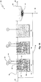
- the present invention relates more specifically to biological nitrifying wastewater as may be performed in a plant 100 illustrated schematically in Figure 1 .
- An influent wastewater stream 30 is biologically treated by passing through plant 100 to produce a clarified effluent stream 36.
- Plant 100 includes a reactor 10 and a clarifier 20 in fluid communication such that wastewater flows through reactor 10.
- reactor 10 is a portion of plant 100 where the biological treatment occurs. It is appreciated that more than one reactor may be used in a wastewater treatment plant as is shown in Figure 1A .
- At least one reactor such as reactor 10 is included.
- Reactor 10 is designed to meet a specific objective of enabling and supporting biological treatment.
- plant 100 is designed such that wastewater, in passing through the plant, resides in reactor 10 for a selected period of time sufficient to meet the biological treatment objective of the reactor.
- Sensors 14 and 16, for example, may be deployed to provide for measuring process variables indicative of operating conditions of plant 10. While sensors 14, 16 are illustrated in Figure 1 disposed in reactor 10, it is appreciated that one ore more sensors can be disposed at any of various sites in plant 10 and be useful, perhaps in different ways, in assessing plant operation and the efficiency of the overall biological wastewater treatment process. See, for example, Figures 1A and 2 .
- Microorganisms can perform a variety of treatment processes. Some microorganisms can remove BOD, while other microorganisms can perform nitrification, while others can perform denitrification. Furthermore, and in the way of an example, some microorganisms can be utilized in a wastewater treatment process to remove phosphorus.
- the present invention entails a wastewater treatment process or system that utilizes an integrated fixed film activated sludge (IFAS) process.
- IFAS integrated fixed film activated sludge
- the microorganisms or biomass reside suspended in the mixed liquor that is typical in conventional activated sludge processes, and the biomass also resides on media or carriers 42. See Figure 1 . That is, the biomass in an IFAS process can be found suspended in the mixed liquor and on the carriers 42.
- the amount of biomass (nitrifying and organic substrate removing microorganisms) on the carriers 42 as well as in the mixed liquor can vary. During some periods, the amount of biomass or the density of the biomass on the carriers 42 is greater than at other times.
- Figure 1A illustrates another example of an IFAS process.
- the process includes three reactors, R1, R2 and R3.
- Reactors R1 and R2 include the biofilm carriers 42 while reactor R3, located downstream from R1 and R2, does not include biofilm carriers. All three reactors in this example are aerated. Consistent with the present invention as described above, aeration may be intermittent (on/off) or varied for reactors R1 and R2 under conditions of low NH 3 loading and warm temperature. In such cases, as discussed before, most of the nitrification occurs in the suspended biomass.
- the processes shown in Figures 1 and 1A are exemplary processes and that the concepts of the present invention can be applied in many biological wastewater treatment processes.
- the present invention recognizes that biological activity exists in a wastewater treatment process with both the biomass in the mixed liquor and the biomass on the carriers 42.
- One principle that the present invention recognizes and appreciates is that at certain times and under certain conditions there may be more biological activity associated with the biomass in the mixed liquor than at other times. Likewise, at certain times and under certain conditions there may be more biological activity associated with the biomass on the carriers 42 than at other times.
- the present invention envisions a control process that is efficient and makes effective use of the biomass in the mixed liquor and on the carriers 42.
- One approach to controlling nitrification for example, is to control the dissolved oxygen concentration in reactor 10 such that in one mode of operation, the primary biological activity that contributes to biological treatment emanates from the biomass in the mixed liquor.
- the wastewater treatment process described herein can function while maintaining the dissolved oxygen concentration relatively low. This, of course, requires less aeration which in turn reduces energy costs. Under such conditions, there is sufficient nitrifying biomass in the mixed liquor to perform adequate nitrification under conditions where the dissolved oxygen concentration is maintained relatively low. Under these conditions, individual carrier-filled reactors, as shown for example in Figure 1A , may be intermittently aerated (implementing an air on/air off scenario) for fixed time periods while monitoring the NH 4 near the reactor discharge point. If a relatively long period of zero aeration is utilized, it may be necessary to include short aeration pulses within this overall period.
- Outlet screens 32 ( Figure 1A ) can be positioned such that screen blockage due to media migration is minimized during carrier mixing-limited conditions, or alternatively, mechanical mixers can be utilized and operated during air-off periods. Even during these times where the dissolved oxygen concentration is maintained relatively low, the nitrifying biomass on the carriers 42 may still contribute to the total nitrification process. The contribution made by the biomass on the carriers 42 may be small compared to the contribution made by the biomass suspended in the mixed liquor. Such conditions will change and as an example, seasons will change and the wastewater treatment process will be exposed to colder temperatures or there might be sudden load increases. Over a period of time, as the wastewater temperature decreases, biomass concentrations in the mixed liquor will decrease and more biomass will grow on the carriers 42.
- the control system reacts by increasing the dissolved oxygen concentration to a relatively high dissolved oxygen concentration.
- the relatively high dissolved oxygen concentration causes the nitrifying biomass on the carriers 42 to significantly contribute to the nitrification process.
- the nitrifying biomass in the second mode of operation will include substantially more nitrifying activity than was associated with the nitrifying biomass on the carriers 42 during the first mode of operation where the dissolved oxygen concentration was maintained at a relatively low concentration.
- both the biomass on the carriers and the biomass in the mixed liquor contribute to total nitrification.
- the ammonia sensors 14 measure the concentration of ammonia in the mixed liquor in the reactor 10, or in a subsequent reactor. When the ammonia concentration exceeds a threshold value or falls outside of a target ammonia concentration range, the system can gradually increase aeration so as to raise the dissolved oxygen concentration in the reactor 10 sufficient to nitrify the mixed liquor in reactor. Likewise, when the ammonia concentration in the reactor is extremely low, then the control system can reduce aeration and hence reduce energy costs because such is unnecessary.
- the ammonia level in incoming wastewater is known to vary, both diurnally and from season to season. Thus required net rate of nitrification can be affected by the changing concentration of ammonia in influent 30.
- the temperature of the wastewater is known to have an effect on the rate of nitrification as well as an effect on the amount of ammonia in the wastewater.
- nitrification proceeds at a lower rate than during relatively warm parts of a day or warm periods of the year.
- ammoniafication proceeds more slowly at lower temperatures than at higher temperatures.
- nitrification reactor 10 For a given set of operating conditions, such as temperature, influent ammonia loading, and flow rate through plant 10, the rate at which ammonia is converted to nitrate is one indicator of the effectiveness of nitrification reactor 10.
- influent ammonia loading and temperature may vary, it is commonly understood that there is a minimum net nitrification rate, below which the reactor 10 maybe deemed ineffective.
- nitrification is usually primarily performed by the biomass in the mixed liquor.
- the control system will raise the dissolved oxygen concentration set point.
- the dissolved oxygen concentration set point is raised, then this calls for additional aeration in order to raise the dissolved oxygen concentration in the reactor.
- the raising of the dissolved oxygen concentration set point will increase the dissolved oxygen concentration in the reactor and that will increase the nitrifying activity of the biomass on the carriers.
- substantial nitrification is carried out by both the biomass in the mixed liquor and the biomass on the carriers.
- a control approach can be relatively simple.
- a simple control approach is to have dissolved oxygen control based on ammonia measurement.
- the dissolved oxygen concentration is gradually increased or decreased based on the measured ammonia concentration in the reactor or in a subsequent reactor.
- the dissolved oxygen is increased by increasing aeration which generally increases mixing intensity in the reactor. Increasing the dissolved oxygen concentration and mixing intensity will increase the biological activity of the biomass on the carriers and this will in turn increase the contributions of the biomass on the carriers to the total biological treatment being performed.
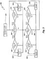
- FIG. 3 a flow chart 200 that describes an exemplary control logic. It should be appreciated that there are numerous logic control schemes that can be employed, and that the logic control shown in Figure 3 is simply one example. Before describing the logic, it is of use to discuss measured, calculated, and controlled variables and operating parameters associated with the control system and the plant.
- the measured variables are the ammonia concentration (NH 3 ) and the dissolved oxygen (DO) concentration expressed, for example in mg/l, in the wastewater.
- the values of the measured variables, NH 3 and DO, at any arbitrary time are acquired from sensors 14, 16 (or measured in a subsequent reactor) by conventional and well-known means.
- change in ammonia level for a given change in dissolved oxygen can be used.
- the controlled variable is the aeration rate, AR, expressed, for example, in cfm of air flow.
- AR aeration rate
- Aeration rate may be varied, for example, by an electronic control valve responding to a command signal from the control system in a conventional and well known manner.
- Parameters are values that various variables may take on or may be limited or constrained by during the operation of the control system.
- the dissolved oxygen DO maybe continuously controlled by varying AR to keep the DO as close as practically possible to a set point value, DOSP.
- DOSP set point value
- a second range for DOSP can be employed when it is desired to increase the nitrifying activity of the biomass on the carriers. These ranges are known based on experience by those skilled in wastewater treatment.
- the first range represents a practical range in which to vary DO and provide nitrification mainly or primarily due to the activated sludge 40.
- the second range represents a practical range in which to vary the dissolved oxygen concentration where the dissolved oxygen concentration is effective to increase the nitrifying activity of the biomass on the carriers 42 and increasing the mixing of the carriers into the total reactor volume.
- the first dissolved oxygen set point may include a range of 0.5mg/L to 2.0mg/L.
- this dissolved oxygen concentration range will encourage substantial nitrifying activity from the biomass in the mixed liquor and which will result in the biomass in mixed liquor primarily contributing to nitrification.
- the dissolved oxygen set point for the second range is 2.5mg/L to 5mg/L.
- this dissolved oxygen range is it postulated that this dissolved oxygen range will increase nitrifying activity of the biomass on the carriers 42 and increase the mixing of the carriers into the total reactor volume such that in general, the biomass on the carriers will contribute significantly to nitrification.
- this second dissolved oxygen set point range it is believed that both the biomass in the mixed liquor and the biomass on the carriers will contribute significantly to total nitrification.
- the ammonia concentration NH 3 has a target value which is an objective of the wastewater nitrification process. This is generally the level to which it is desired to reduce the ammonia concentration before the wastewater moves to a subsequent stage in the treatment plant.
- the target value of NH 3 may be based on effluent requirements or legal limits for returning treated water to a river or basin.
- a typical target range for ammonia is 0.2 - 10mg/L.
- a minimum value of the net nitrification rate for the first mode to remain selected is an experience-based value based on characteristics of the activated sludge and the cost of aeration.
- a maximum value of net nitrification rate for the second mode to remain selected generally exists, and the value is likewise experience based and based at least partly on the cost of aeration.
- the control system then operates with the objective of keeping net nitrification rate between a minimum value, and the maximum value in order to achieve the desired ammonia level in the effluent.
- aeration rate there is a minimum aeration rate obtainable with whatever aeration system is implemented. In general the minimum aeration rate is 0 or near 0 cfm. Likewise, there could be a maximum aeration rate associated with the particular aeration system utilized.
- the control system is depicted in the exemplary flow chart of Figure 3 .
- the control system is designed to operate in a cyclic fashion wherein a cycle begins at block 210.
- the measurements and control responses called for beginning with block 210 are executed to reach point 240, and the cycle ends by returning to block 210.
- the time required for one cycle is time step ⁇ T.
- DOSP and AR are potentially changed in each step by incrementing or decrementing by a fixed value or step, ⁇ DOSP and ⁇ AR, respectively.
- Step values ⁇ T, ⁇ DOSP, and ⁇ AR values can be adjusted for stability and responsiveness of the control system by well known control system methods. Typical values for these control variables and parameters are well known and appreciated by those skilled in the art, and it is appreciated that various values can be employed depending on circumstances and conditions surrounding treatment.
- an initialization step 201 is provided to start the control system working.
- the initialization adjustment step is followed by a dissolved oxygen set point adjustment step that commences with block 220 to adjust the dissolved oxygen set point according to the current ammonia level in the wastewater.
- the dissolved oxygen set point step is followed by the aeration level adjustment step, which begins with block 230 and ends at point 240 from whence control passes for the next time step back to the dissolved oxygen set point step at block 220.
- Initialization step is only executed at a startup of the control system. In this step, through operator entry or other means of entry, the various parameters of the plant and the control system as described here are entered..
- the current ammonia level is sensed and compared to the ammonia target for the treatment occurring in reactor 10. If the ammonia level is above the target level, control passes to block 222 where the current dissolved oxygen set point is compared to the maximum allowable dissolved oxygen set points. If the dissolved oxygen set point is not maximized, it is incremented, or increased, by the parameter, ⁇ DO SP . If the dissolved oxygen set point is maximized, no control action is taken and control passes to the aeration adjustment step.
- the aeration adjustment step begins with block 230 where the currently measured dissolved oxygen in the wastewater is compared with the current dissolved oxygen set point. If the currently measured dissolved oxygen is below the current set point value, control passes to block 232, and if the measured dissolved oxygen is above the current set point, control passes to block 231. If the dissolved oxygen set point is at the set point, no control action occurs as a result of the block 230 decisions.
- control passes to block 232 the current aeration level is compared to the value that was set as the maximum allowable or obtainable aeration level. If aeration is not maximized, the aeration is incremented by the amount ⁇ AR (block 234 ) and control passes to the next dissolved oxygen set point step at block 220.
- the current aeration level is compared to the value that was set as the minimum allowable or obtainable aeration level. If aeration is not minimized, the aeration is decremented by the amount ⁇ AR (block 233 ) and control passes to the next dissolved oxygen set point step at block 220 . If aeration is already minimized, no control action results and control passes to the next dissolved oxygen set point step at block 220.
- any control decision based on comparing a variable value and determining if, for example, the value is equal to a specific set point or target value involves numerical tolerances. Such comparisons are to be implemented by using small tolerances about the actual desired set point value to avoid instability. When, for example, the measured dissolved oxygen is compared to a target level, it is to be considered equal to the set point level it if is within plus or minus a very small range about the set point value. It is well within the skill of the ordinarily skilled artisan to set these small comparison ranges, sometimes called deltas.
- the first level of control looks at NH 3 levels and determines if the DO set point should be raised or lowered. Then, in the succeeding second level, the control logic looks at measured DO and determines if the aeration should be increased or decreased. It is appreciated that this order could be reversed. For example, the section of the control logic directed at determining if the DO set point should be raised or lowered could be at the second level while the determination whether aeration should be increased or decreased could occur at the first level. Many variations of this type can be implemented.
- the present invention has been described in the context of a nitrification process. However, it should be understood and appreciated that the present invention can be utilized in various types of biological wastewater treatment processes including, but not limited to, BOD removal, phosphorous removal, and denitrification. Further, the process shown in Figure 1 is a simple single train process. It is appreciated that the present invention can be incorporated into a multi-train process for a wide variety of biological wastewater treatment processes. In such a multi-train configuration, illustrated in Figure 2 , process variables such as dissolved oxygen, ammonia concentration can be monitored at various locations in the trains. If the trains are producing a common effluent, process variables can be monitored in the common effluent.
- each train includes four reactors, an anoxic reactor Ax followed by three aerobic reactors, Ae1, Ae2 and Ae3.
- Various monitoring approaches can be implemented for such process trains.
- NH 3 is monitored before the influent is directed into each of the trains and NH 3 is also monitored in the final effluent that is taken from all three trains.
- NH 3 is monitored in the effluent from each train, before the respective effluents are combined.
- dissolved oxygen concentration is measured or monitored in the second aerobic reactor Ae2 in each train.
- the biofilm carriers 42 may have a tendency to accumulate about the surface of the wastewater.
- the biofilm carriers 42 may have a tendency to accumulate at the outlet of the reactor 10, and in some cases it may be possible that the biofilm carriers 42 could inhibit or restrict the flow of wastewater through the outlet of the reactor 10 and to the clarifier 20. Therefore, to reduce this tendency, the present invention could provide means in the area of the reactor outlet to prevent the biofilm carriers 42 from restricting or inhibiting the flow of wastewater through this area.
- One such means is the provision of an air distribution means near the outlet of the reactor that would disburse air into this area and effectively prevent the biofilm carriers 42 from accumulating in the outlet area.
- the amount of air distributed in this area could be controlled such that it would not impact the basic control concerning operation in the first and second modes. That is, the air supplied here would be controlled such that when the system was operating in the first mode of operation, that this particular amount of air would not substantially activate the microorganisms associated with the biofilm carriers 42.
- Another approach to dealing with this concern is to provide outlets in the lower portion of the reactor 10 . In this case, the biofilm carriers, at least in the first mode of operation, would not inhibit the flow of wastewater through such lower disposed outlets.
Landscapes
- Life Sciences & Earth Sciences (AREA)
- Biodiversity & Conservation Biology (AREA)
- Microbiology (AREA)
- Hydrology & Water Resources (AREA)
- Engineering & Computer Science (AREA)
- Environmental & Geological Engineering (AREA)
- Water Supply & Treatment (AREA)
- Chemical & Material Sciences (AREA)
- Organic Chemistry (AREA)
- Health & Medical Sciences (AREA)
- Molecular Biology (AREA)
- Purification Treatments By Anaerobic Or Anaerobic And Aerobic Bacteria Or Animals (AREA)
- Activated Sludge Processes (AREA)
Description
- The present invention is related to wastewater nitrifying processes wherein aeration is utilized to promote biological treatment of the wastewater. More specifically, the invention relates to controlling aeration in multiple modes of operation of a biological wastewater treatment reactor wherein the modes are associated with substantially different aeration levels.
- Wastewater treatment systems are designed to remove contaminants from wastewater. For many years, many wastewater treatment systems have been designed for biological treatment. For example, biological treatment is utilized to remove BOD from the wastewater. Another example of biological treatment involves removing ammonia from wastewater. This is referred to as nitrification and denitrification. Another example of biological treatment is the use of microorganisms to remove phosphorus from wastewater.
- More particularly, biological organisms or microbes generally extant in wastewater can be stimulated to perform wastewater treatment processes by consuming waste materials, and in some cases, producing other materials or compounds that are acceptable, or that can be subsequently removed from the wastewater.
- Generally, sustained activation of microbial populations in wastewater requires oxygen, in that most of the organisms are aerobic in nature. Commonly, oxygen is provided by aerating the wastewater. Aeration may be done in various ways. However, typical approaches to aeration can be costly in terms of the energy required to operate pumps, compressors, agitators, stirrers, and the like. Minimizing energy costs is a major factor in the operation of wastewater treatment plants, and aeration costs can be a major part of total wastewater treatment plant energy costs.
WO 2006/058097 discloses a wastewater treatment system including a biological reactor that, includes a fixed-film media in at least one controlled-reaction-volume module, at least one mixer and least one controller for regulating the operation of the wastewater treatment system, capable of alternating the environment within the controlled-reaction- volume module among aerobic, anoxic, anaerobic environments, or any combinations thereof. - There has been and continues to be a need for biological wastewater treatment systems and processes that control aeration and provide for an efficient cost-effective means for biologically treating wastewater.
- The present invention relates to a process for biologically nitrifying wastewater utilizing an integrated fixed film activated sludge process. The invention is defined by the appended set of claims. By the traditional operation of such plants the mixing of the media with the mixed liquor and the wastewater is continuously ensured by intensive aeration which also ensure sufficient oxygen level to ensure biological activity on the media. In this method, wastewater is mixed with activated sludge to form mixed liquor. The mixed liquor is treated in a reactor having biomass disposed on media or carriers and also having biomass suspended in the mixed liquor. The aeration to the reactor having the mixed liquor is varied so as to efficiently aerate and supply dissolved oxygen to the mixed liquor. In one mode of operation, the aeration and dissolved oxygen concentration is maintained relatively low because the biomass suspended in the mixed liquor is sufficient to primarily carry out the required biological treatment. During such conditions the carriers are typically floating in the upper section of the biological reactor and are not taking part in the purification/treatment process of the wastewater. In a second mode of operation, the aeration to the reactor is increased and this effectively increases the dissolved oxygen concentration in the reactor which increases the biological activity of the biomass on the carriers which in turn generally increases the contribution of the biomass on the carriers to the biological treatment, and the carriers are generally evenly distributed in the reactor due to the higher aeration activity.
- In one particular embodiment of the present invention, a method of biologically nitrifying wastewater utilizing an integrated fixed film activated sludge process is provided. Here, the method includes mixing the wastewater with activated sludge to form mixed liquor. The mixed liquor is biologically treated in a reactor that includes biomass on the carriers and biomass suspended in the mixed liquor. The amount of biomass on the carriers will vary depending on temperature and the loading of organic matter and ammonia nitrogen in relation to the amount of activated sludge in the system (MLSS). The method includes controlling the dissolved oxygen concentration in the reactor in such a way that the biomass on the carriers is only removing pollutants (organic matter and ammonia) when the mixed liquor is not able to handle the complete treatment by itself. i.e., the carriers are only "working" when required. The dissolved oxygen concentration in the reactor is maintained relatively low when the biomass in the mixed liquor can perform the required biological treatment. Under certain conditions the biomass in the mixed liquor is unable to biologically treat the wastewater without substantial contributions from the biomass on the carriers. When this is the case, the dissolved oxygen concentration in the mixed liquor is raised and this enables the biomass on the carriers to substantially contribute to the biological treatment of the wastewater. More specifically the method includes measuring the concentration of ammonia in the mixed liquor and comparing it to an ammonia concentration target;- measuring the concentration of dissolved oxygen in the mixed liquor;- gradually increasing aeration rate when the ammonia concentration exceeds the ammonia concentration target or reducing aeration rate in the reactor when the ammonia concentration is below the ammonia concentration target, wherein the dissolved oxygen concentration in the reactor is controlled by varying the aeration rate to keep the dissolved oxygen concentration as close as practically possible to a set point value within a setpoint range;wherein, in a first mode of operation a dissolved oxygen concentration setpoint range of 0.5-2.0 mg/L is employed, the nitrification of the wastewater being primarily performed by the suspended biomass in the mixed liquor; and wherein, in a second mode of operation a dissolved oxygen concentration setpoint range of 2.5-5.0 mg/L is employed , the nitrification of the wastewater being performed by the suspended biomass in the mixed liquor and the biomass on the carriers.
- Other objects and advantages of the present invention will become apparent and obvious from a study of the following description and the accompanying drawings which are merely illustrative of such invention.
-
-
Figure 1 is a schematic of a wastewater treatment plant in accordance with an embodiment of the present invention. -
Figure 1A is a schematic of a wastewater treatment plant in accordance with an alternate embodiment of the present invention. -
Figure 2 is a schematic of a wastewater treatment plant in accordance with a multi-train embodiment of the present invention. -
Figure 3 is a flow chart describing exemplary control logic appropriate to the present invention. - The present invention relates to wastewater treatment processes to remove pollutants or contaminants from wastewater and generally to render the water cleaner and less harmful to the environment. Typical pollutants in wastewater, particularly municipal wastewater, comprise carbonaceous organics, organic N and ammonia. The present invention relates more specifically to biological nitrifying wastewater as may be performed in a
plant 100 illustrated schematically inFigure 1 . Aninfluent wastewater stream 30 is biologically treated by passing throughplant 100 to produce a clarifiedeffluent stream 36.Plant 100 includes areactor 10 and aclarifier 20 in fluid communication such that wastewater flows throughreactor 10. Generally,reactor 10 is a portion ofplant 100 where the biological treatment occurs. It is appreciated that more than one reactor may be used in a wastewater treatment plant as is shown inFigure 1A . However, where biological treatment is a design objective, at least one reactor such asreactor 10 is included.Reactor 10 is designed to meet a specific objective of enabling and supporting biological treatment. Generally,plant 100 is designed such that wastewater, in passing through the plant, resides inreactor 10 for a selected period of time sufficient to meet the biological treatment objective of the reactor.Sensors plant 10. Whilesensors Figure 1 disposed inreactor 10, it is appreciated that one ore more sensors can be disposed at any of various sites inplant 10 and be useful, perhaps in different ways, in assessing plant operation and the efficiency of the overall biological wastewater treatment process. See, for example,Figures 1A and2 . - Biological treatment of wastewater utilizes microorganisms or biomass to treat the wastewater. Microorganisms can perform a variety of treatment processes. Some microorganisms can remove BOD, while other microorganisms can perform nitrification, while others can perform denitrification. Furthermore, and in the way of an example, some microorganisms can be utilized in a wastewater treatment process to remove phosphorus.
- The present invention entails a wastewater treatment process or system that utilizes an integrated fixed film activated sludge (IFAS) process. Here the microorganisms or biomass reside suspended in the mixed liquor that is typical in conventional activated sludge processes, and the biomass also resides on media or
carriers 42. SeeFigure 1 . That is, the biomass in an IFAS process can be found suspended in the mixed liquor and on thecarriers 42. As conditions such as temperature and the amount of substrate (organic loading) and loading of ammonia nitrogen change, the amount of biomass (nitrifying and organic substrate removing microorganisms) on thecarriers 42 as well as in the mixed liquor can vary. During some periods, the amount of biomass or the density of the biomass on thecarriers 42 is greater than at other times. For example, during seasonal warm weather there may be less biomass on thecarriers 42 and there may be more nitrifying microorganisms suspended in the mixed liquor. Similarly, as temperatures become lower and there is a seasonal change to colder weather, the amount of nitrifying biomass in the mixed liquor may decrease. This change in population is not instantaneous. It usually occurs gradually. But the change in ammonia loading may change during the daily loading variations. -
Figure 1A illustrates another example of an IFAS process. In this example the process includes three reactors, R1, R2 and R3. Reactors R1 and R2 include thebiofilm carriers 42 while reactor R3, located downstream from R1 and R2, does not include biofilm carriers. All three reactors in this example are aerated. Consistent with the present invention as described above, aeration may be intermittent (on/off) or varied for reactors R1 and R2 under conditions of low NH3 loading and warm temperature. In such cases, as discussed before, most of the nitrification occurs in the suspended biomass. Again, it should be appreciated that the processes shown inFigures 1 and1A are exemplary processes and that the concepts of the present invention can be applied in many biological wastewater treatment processes. - The present invention recognizes that biological activity exists in a wastewater treatment process with both the biomass in the mixed liquor and the biomass on the
carriers 42. One principle that the present invention recognizes and appreciates is that at certain times and under certain conditions there may be more biological activity associated with the biomass in the mixed liquor than at other times. Likewise, at certain times and under certain conditions there may be more biological activity associated with the biomass on thecarriers 42 than at other times. The present invention envisions a control process that is efficient and makes effective use of the biomass in the mixed liquor and on thecarriers 42. One approach to controlling nitrification, for example, is to control the dissolved oxygen concentration inreactor 10 such that in one mode of operation, the primary biological activity that contributes to biological treatment emanates from the biomass in the mixed liquor. For example, when temperatures are relatively high during summer months, the wastewater treatment process described herein can function while maintaining the dissolved oxygen concentration relatively low. This, of course, requires less aeration which in turn reduces energy costs. Under such conditions, there is sufficient nitrifying biomass in the mixed liquor to perform adequate nitrification under conditions where the dissolved oxygen concentration is maintained relatively low. Under these conditions, individual carrier-filled reactors, as shown for example inFigure 1A , may be intermittently aerated (implementing an air on/air off scenario) for fixed time periods while monitoring the NH4 near the reactor discharge point. If a relatively long period of zero aeration is utilized, it may be necessary to include short aeration pulses within this overall period. Outlet screens 32 (Figure 1A ) can be positioned such that screen blockage due to media migration is minimized during carrier mixing-limited conditions, or alternatively, mechanical mixers can be utilized and operated during air-off periods. Even during these times where the dissolved oxygen concentration is maintained relatively low, the nitrifying biomass on thecarriers 42 may still contribute to the total nitrification process. The contribution made by the biomass on thecarriers 42 may be small compared to the contribution made by the biomass suspended in the mixed liquor. Such conditions will change and as an example, seasons will change and the wastewater treatment process will be exposed to colder temperatures or there might be sudden load increases. Over a period of time, as the wastewater temperature decreases, biomass concentrations in the mixed liquor will decrease and more biomass will grow on thecarriers 42. When this occurs, there may be insufficient biomass in the mixed liquor to adequately nitrify within the mixed liquor alone at a relatively low dissolved oxygen concentration and the mass transfer limitations across the biofilms would limit the amount of nitrification which could potentially occur within the fixed film on the carriers. Hence, to perform adequate nitrification in the mixed liquor, the control system reacts by increasing the dissolved oxygen concentration to a relatively high dissolved oxygen concentration. In a separate mode of operation, the relatively high dissolved oxygen concentration causes the nitrifying biomass on thecarriers 42 to significantly contribute to the nitrification process. It is postulated that at a relatively high dissolved oxygen concentration, that the nitrifying biomass in the second mode of operation will include substantially more nitrifying activity than was associated with the nitrifying biomass on thecarriers 42 during the first mode of operation where the dissolved oxygen concentration was maintained at a relatively low concentration. In the second mode of operation where the dissolved oxygen concentration is maintained relatively high, both the biomass on the carriers and the biomass in the mixed liquor contribute to total nitrification. - There are numerous ways to control the wastewater treatment process described so as to efficiently use energy and effectively treat the wastewater. In the case of a nitrification process for example, the
ammonia sensors 14 measure the concentration of ammonia in the mixed liquor in thereactor 10, or in a subsequent reactor. When the ammonia concentration exceeds a threshold value or falls outside of a target ammonia concentration range, the system can gradually increase aeration so as to raise the dissolved oxygen concentration in thereactor 10 sufficient to nitrify the mixed liquor in reactor. Likewise, when the ammonia concentration in the reactor is extremely low, then the control system can reduce aeration and hence reduce energy costs because such is unnecessary. - The ammonia level in incoming wastewater is known to vary, both diurnally and from season to season. Thus required net rate of nitrification can be affected by the changing concentration of ammonia in
influent 30. Likewise, the temperature of the wastewater is known to have an effect on the rate of nitrification as well as an effect on the amount of ammonia in the wastewater. During relatively cold parts of the day or of the year, nitrification proceeds at a lower rate than during relatively warm parts of a day or warm periods of the year. Likewise, while wastewater is in transit to plant 10, for example, ammoniafication proceeds more slowly at lower temperatures than at higher temperatures. - Generally, for a given set of operating conditions, such as temperature, influent ammonia loading, and flow rate through
plant 10, the rate at which ammonia is converted to nitrate is one indicator of the effectiveness ofnitrification reactor 10. Those of ordinary skill in the operation of wastewater biological treatment plants are cognizant of, for example, how many pounds of ammonia must be converted per hour for generally acceptable operation. While influent ammonia loading and temperature may vary, it is commonly understood that there is a minimum net nitrification rate, below which thereactor 10 maybe deemed ineffective. For example, when operating at a relatively low dissolved oxygen concentration set point, nitrification is usually primarily performed by the biomass in the mixed liquor. When the ammonia concentration increases over a threshold or target level, or when the net nitrification rate falls below an established minimum, the control system will raise the dissolved oxygen concentration set point. When the dissolved oxygen concentration set point is raised, then this calls for additional aeration in order to raise the dissolved oxygen concentration in the reactor. The raising of the dissolved oxygen concentration set point will increase the dissolved oxygen concentration in the reactor and that will increase the nitrifying activity of the biomass on the carriers. Now, at this raised or elevated dissolved oxygen concentration set point, substantial nitrification is carried out by both the biomass in the mixed liquor and the biomass on the carriers. - There are numerous control approaches to controlling biological activity of the biomass to reduce and conserve energy. In
Figure 3 , to be described later, there is disclosed a relatively sophisticated control process for nitrifying wastewater. However, a control approach can be relatively simple. A simple control approach is to have dissolved oxygen control based on ammonia measurement. The dissolved oxygen concentration is gradually increased or decreased based on the measured ammonia concentration in the reactor or in a subsequent reactor. The dissolved oxygen is increased by increasing aeration which generally increases mixing intensity in the reactor. Increasing the dissolved oxygen concentration and mixing intensity will increase the biological activity of the biomass on the carriers and this will in turn increase the contributions of the biomass on the carriers to the total biological treatment being performed. - Turning now to one specific exemplary embodiment of a control system operable to control a nitrification process as described above, there is shown in
Figure 3 aflow chart 200 that describes an exemplary control logic. It should be appreciated that there are numerous logic control schemes that can be employed, and that the logic control shown inFigure 3 is simply one example. Before describing the logic, it is of use to discuss measured, calculated, and controlled variables and operating parameters associated with the control system and the plant. The measured variables are the ammonia concentration (NH3) and the dissolved oxygen (DO) concentration expressed, for example in mg/l, in the wastewater. The values of the measured variables, NH3 and DO, at any arbitrary time are acquired fromsensors 14, 16 (or measured in a subsequent reactor) by conventional and well-known means. For purposes of discussing one exemplary approach, change in ammonia level for a given change in dissolved oxygen (ΔNH3/ΔDO) can be used. The controlled variable is the aeration rate, AR, expressed, for example, in cfm of air flow. There are known ways to vary aeration. Aeration rate may be varied, for example, by an electronic control valve responding to a command signal from the control system in a conventional and well known manner. - Parameters are values that various variables may take on or may be limited or constrained by during the operation of the control system. The dissolved oxygen DO maybe continuously controlled by varying AR to keep the DO as close as practically possible to a set point value, DOSP. There is a known first range for DOSP for operating in the first mode where nitrification is mainly or primarily carried out by the activated
sludge 40. A second range for DOSP can be employed when it is desired to increase the nitrifying activity of the biomass on the carriers. These ranges are known based on experience by those skilled in wastewater treatment. The first range represents a practical range in which to vary DO and provide nitrification mainly or primarily due to the activatedsludge 40. The second range represents a practical range in which to vary the dissolved oxygen concentration where the dissolved oxygen concentration is effective to increase the nitrifying activity of the biomass on thecarriers 42 and increasing the mixing of the carriers into the total reactor volume. In the way of an example, the first dissolved oxygen set point may include a range of 0.5mg/L to 2.0mg/L. In this example, this dissolved oxygen concentration range will encourage substantial nitrifying activity from the biomass in the mixed liquor and which will result in the biomass in mixed liquor primarily contributing to nitrification. In this example, the dissolved oxygen set point for the second range is 2.5mg/L to 5mg/L. In this dissolved oxygen range, is it postulated that this dissolved oxygen range will increase nitrifying activity of the biomass on thecarriers 42 and increase the mixing of the carriers into the total reactor volume such that in general, the biomass on the carriers will contribute significantly to nitrification. In this second dissolved oxygen set point range, it is believed that both the biomass in the mixed liquor and the biomass on the carriers will contribute significantly to total nitrification. These ranges are experience-based and may be determined based on, among other things, energy costs. - The ammonia concentration NH3 has a target value which is an objective of the wastewater nitrification process. This is generally the level to which it is desired to reduce the ammonia concentration before the wastewater moves to a subsequent stage in the treatment plant. The target value of NH3 may be based on effluent requirements or legal limits for returning treated water to a river or basin. A typical target range for ammonia is 0.2 - 10mg/L.
- In one exemplary embodiment, a minimum value of the net nitrification rate for the first mode to remain selected is an experience-based value based on characteristics of the activated sludge and the cost of aeration. Oppositely, a maximum value of net nitrification rate for the second mode to remain selected generally exists, and the value is likewise experience based and based at least partly on the cost of aeration. The control system, then operates with the objective of keeping net nitrification rate between a minimum value, and the maximum value in order to achieve the desired ammonia level in the effluent.
- There is a minimum aeration rate obtainable with whatever aeration system is implemented. In general the minimum aeration rate is 0 or near 0 cfm. Likewise, there could be a maximum aeration rate associated with the particular aeration system utilized.
- The control system is depicted in the exemplary flow chart of
Figure 3 . There are many different ways in which the logic can be designed. What follows is simply one exemplary approach. Once initialized (block 201), the control system is designed to operate in a cyclic fashion wherein a cycle begins at block 210. The measurements and control responses called for beginning with block 210 are executed to reachpoint 240, and the cycle ends by returning to block 210. The time required for one cycle is time step δT. DOSP and AR are potentially changed in each step by incrementing or decrementing by a fixed value or step, δDOSP and δAR, respectively. Step values δT, δDOSP, and δAR values can be adjusted for stability and responsiveness of the control system by well known control system methods. Typical values for these control variables and parameters are well known and appreciated by those skilled in the art, and it is appreciated that various values can be employed depending on circumstances and conditions surrounding treatment. - Returning now to
Figure 3 and considering the control logic or strategy, aninitialization step 201 is provided to start the control system working. The initialization adjustment step is followed by a dissolved oxygen set point adjustment step that commences withblock 220 to adjust the dissolved oxygen set point according to the current ammonia level in the wastewater. The dissolved oxygen set point step is followed by the aeration level adjustment step, which begins withblock 230 and ends atpoint 240 from whence control passes for the next time step back to the dissolved oxygen set point step atblock 220. - Initialization step, block 201, is only executed at a startup of the control system. In this step, through operator entry or other means of entry, the various parameters of the plant and the control system as described here are entered..
- After completion of the initialization step, control passes to the dissolved oxygen set point adjustment step, commencing with
block 220. The current ammonia level is sensed and compared to the ammonia target for the treatment occurring inreactor 10. If the ammonia level is above the target level, control passes to block 222 where the current dissolved oxygen set point is compared to the maximum allowable dissolved oxygen set points. If the dissolved oxygen set point is not maximized, it is incremented, or increased, by the parameter, δDOSP. If the dissolved oxygen set point is maximized, no control action is taken and control passes to the aeration adjustment step. - Returning now to block 220, if the ammonia level is below the target, control passes to block 221 where the current dissolved oxygen set point is compared to the minimum allowable dissolved oxygen set point. If the dissolved oxygen set point is not minimized, it is decremented, or decreased, by the parameter, δDOSP, block 223. If the dissolved oxygen set point is minimized, no control action is taken and control passes to the aeration adjustment step.
- The aeration adjustment step begins with
block 230 where the currently measured dissolved oxygen in the wastewater is compared with the current dissolved oxygen set point. If the currently measured dissolved oxygen is below the current set point value, control passes to block 232, and if the measured dissolved oxygen is above the current set point, control passes to block 231. If the dissolved oxygen set point is at the set point, no control action occurs as a result of theblock 230 decisions. When control passes to block 232, the current aeration level is compared to the value that was set as the maximum allowable or obtainable aeration level. If aeration is not maximized, the aeration is incremented by the amount δAR (block 234) and control passes to the next dissolved oxygen set point step atblock 220. If aeration is already maximized, no control action results and control passes to block 220. When control passes to block 231, the current aeration level is compared to the value that was set as the minimum allowable or obtainable aeration level. If aeration is not minimized, the aeration is decremented by the amount δAR (block 233) and control passes to the next dissolved oxygen set point step atblock 220. If aeration is already minimized, no control action results and control passes to the next dissolved oxygen set point step atblock 220. - It is recognized that, as is well known by those skilled in control system design, any control decision based on comparing a variable value and determining if, for example, the value is equal to a specific set point or target value involves numerical tolerances. Such comparisons are to be implemented by using small tolerances about the actual desired set point value to avoid instability. When, for example, the measured dissolved oxygen is compared to a target level, it is to be considered equal to the set point level it if is within plus or minus a very small range about the set point value. It is well within the skill of the ordinarily skilled artisan to set these small comparison ranges, sometimes called deltas.
- In the control logic shown in
Figure 3 , it is appreciated that the first level of control looks at NH3 levels and determines if the DO set point should be raised or lowered. Then, in the succeeding second level, the control logic looks at measured DO and determines if the aeration should be increased or decreased. It is appreciated that this order could be reversed. For example, the section of the control logic directed at determining if the DO set point should be raised or lowered could be at the second level while the determination whether aeration should be increased or decreased could occur at the first level. Many variations of this type can be implemented. - The present invention has been described in the context of a nitrification process. However, it should be understood and appreciated that the present invention can be utilized in various types of biological wastewater treatment processes including, but not limited to, BOD removal, phosphorous removal, and denitrification. Further, the process shown in
Figure 1 is a simple single train process. It is appreciated that the present invention can be incorporated into a multi-train process for a wide variety of biological wastewater treatment processes. In such a multi-train configuration, illustrated inFigure 2 , process variables such as dissolved oxygen, ammonia concentration can be monitored at various locations in the trains. If the trains are producing a common effluent, process variables can be monitored in the common effluent. - In the exemplary system and process shown in
Figure 2 , there are shown three separate process trains that are operatively associated. The basic principles and concepts discussed with respect to the systems and processes shown inFigures 1 and1A apply here. In the case of the individual trains shown inFigure 2 , each train includes four reactors, an anoxic reactor Ax followed by three aerobic reactors, Ae1, Ae2 and Ae3. Various monitoring approaches can be implemented for such process trains. As illustrated inFigure 2 , NH3 is monitored before the influent is directed into each of the trains and NH3 is also monitored in the final effluent that is taken from all three trains. In addition, NH3 is monitored in the effluent from each train, before the respective effluents are combined. Finally, in this example, dissolved oxygen concentration is measured or monitored in the second aerobic reactor Ae2 in each train. - In
Figure 1 , it is appreciated that during the first mode of operation, that thebiofilm carriers 42 may have a tendency to accumulate about the surface of the wastewater. In addition, thebiofilm carriers 42 may have a tendency to accumulate at the outlet of thereactor 10, and in some cases it may be possible that thebiofilm carriers 42 could inhibit or restrict the flow of wastewater through the outlet of thereactor 10 and to theclarifier 20. Therefore, to reduce this tendency, the present invention could provide means in the area of the reactor outlet to prevent thebiofilm carriers 42 from restricting or inhibiting the flow of wastewater through this area. One such means is the provision of an air distribution means near the outlet of the reactor that would disburse air into this area and effectively prevent thebiofilm carriers 42 from accumulating in the outlet area. The amount of air distributed in this area could be controlled such that it would not impact the basic control concerning operation in the first and second modes. That is, the air supplied here would be controlled such that when the system was operating in the first mode of operation, that this particular amount of air would not substantially activate the microorganisms associated with thebiofilm carriers 42. Another approach to dealing with this concern is to provide outlets in the lower portion of thereactor 10. In this case, the biofilm carriers, at least in the first mode of operation, would not inhibit the flow of wastewater through such lower disposed outlets. - The present invention may, of course, be carried out in other ways than those specifically set forth herein without departing from essential characteristics of the invention. The present embodiments are to be considered in all respects as illustrative and not restrictive, and all changes coming within the meaning and equivalency range of the appended claims are intended to be embraced therein.
Claims (3)
- A method of biologically nitrifying wastewater utilizing an integrated fixed film activated sludge process that includes biomass supported on carriers and suspended biomass, the method comprising:mixing the wastewater with activated sludge to form mixed liquor;biologically nitrifying the mixed liquor in a reactor utilizing the biomass on carriers and the biomass suspended in the mixed liquor;wherein the amount of biomass on the carriers varies in function of temperature and the loading of organic matter and ammonia nitrogen in relation to the amount of the activated sludge in the reactor;wherein said method includes:- measuring the concentration of ammonia in the mixed liquor and comparing it to an ammonia concentration target;- measuring the concentration of dissolved oxygen in the mixed liquor;- gradually increasing aeration rate when the ammonia concentration exceeds the ammonia concentration target or reducing aeration rate in the reactor when the ammonia concentration is below the ammonia concentration target, wherein the dissolved oxygen concentration in the reactor is controlled by varying the aeration rate to keep the dissolved oxygen concentration as close as practically possible to a set point value within a setpoint range;wherein, in a first mode of operation a dissolved oxygen concentration setpoint range of 0.5-2.0 mg/L is employed, the nitrification of the wastewater being primarily performed by the suspended biomass in the mixed liquor; andwherein, in a second mode of operation a dissolved oxygen concentration setpoint range of 2.5-5.0 mg/L is employed , the nitrification of the wastewater being performed by the suspended biomass in the mixed liquor and the biomass on the carriers.
- The method according to claim 1 wherein, in the first mode of operation, the carriers are not mixed with the mixed liquor.
- The method according to claim 1 wherein, in the second mode of operation, the carriers are mixed with the mixed liquor.
Applications Claiming Priority (2)
| Application Number | Priority Date | Filing Date | Title |
|---|---|---|---|
| US12/783,807 US8268173B2 (en) | 2010-05-20 | 2010-05-20 | Controlled aeration of integrated fixed-film activated sludge bioreactor systems for the treatment of wastewater |
| PCT/US2011/036594 WO2011146361A1 (en) | 2010-05-20 | 2011-05-16 | Controlled aeration of integrated fixed-film activated sludge bioreactor systems for the treatment of wastewater |
Publications (3)
| Publication Number | Publication Date |
|---|---|
| EP2571819A1 EP2571819A1 (en) | 2013-03-27 |
| EP2571819A4 EP2571819A4 (en) | 2015-08-26 |
| EP2571819B1 true EP2571819B1 (en) | 2017-09-13 |
Family
ID=44971598
Family Applications (1)
| Application Number | Title | Priority Date | Filing Date |
|---|---|---|---|
| EP11784014.0A Not-in-force EP2571819B1 (en) | 2010-05-20 | 2011-05-16 | Controlled aeration of integrated fixed-film activated sludge bioreactor systems for the treatment of wastewater |
Country Status (5)
| Country | Link |
|---|---|
| US (1) | US8268173B2 (en) |
| EP (1) | EP2571819B1 (en) |
| CN (1) | CN102985375B (en) |
| CA (1) | CA2795867C (en) |
| WO (1) | WO2011146361A1 (en) |
Families Citing this family (22)
| Publication number | Priority date | Publication date | Assignee | Title |
|---|---|---|---|---|
| AU2012340306A1 (en) * | 2011-11-16 | 2014-05-08 | Evoqua Water Technologies Llc | Using continuous nitrate measurement to control aeration in an aerated-anoxic process |
| FR2985996B1 (en) * | 2012-01-19 | 2014-02-07 | Saur | METHOD FOR REGULATING AERATION IN A BIOLOGICAL TREATMENT BASIN OF URBAN OR INDUSTRIAL WASTE WATER |
| US9340439B2 (en) | 2012-09-13 | 2016-05-17 | D.C. Water & Sewer Authority | Method and apparatus for nitrogen removal in wastewater treatment |
| MX360501B (en) | 2012-09-13 | 2018-11-05 | D C Water & Sewer Authority | Method and apparatus for nitrogen removal in wastewater treatment. |
| US20140311972A1 (en) * | 2013-04-18 | 2014-10-23 | Malcolm Fabiyi | Nitrification method and system |
| WO2015011213A1 (en) * | 2013-07-24 | 2015-01-29 | Universitat Autonoma De Barcelona | A method and a system for enhancing nitrogen removal in a granular sequencing batch reactor (gsbr) and a computer program product |
| FR3012444B1 (en) * | 2013-10-30 | 2016-01-01 | Degremont | METHOD AND SYSTEM FOR THE BIOLOGICAL TREATMENT OF EFFLUENT, ESPECIALLY WASTEWATER |
| CA2941875A1 (en) * | 2014-03-21 | 2015-09-24 | Parkson Corporation | Wastewater treatment apparatus with dual-level control |
| US9902635B2 (en) | 2014-07-23 | 2018-02-27 | Hampton Roads Sanitation District | Method for deammonification process control using pH, specific conductivity, or ammonia |
| TWI586610B (en) * | 2015-01-15 | 2017-06-11 | 黎明興技術顧問股份有限公司 | Fluidized bed reactor for ammonia laden wastewater and method for treating ammonia laden wastewater |
| ES2579992B1 (en) * | 2015-02-16 | 2017-09-19 | Acciona Agua, S.A. | AIR CONTROL IN TREATMENT OF WASTEWATER THROUGH MONITORING OF NITRIFICATION SUBPRODUCTS |
| CN105776772A (en) * | 2016-05-10 | 2016-07-20 | 王亚明 | Modular type movable microorganism expanding culture device |
| GB201702272D0 (en) * | 2017-02-10 | 2017-03-29 | Vws (Uk) Ltd | Water treatment |
| NL2018967B1 (en) | 2017-05-23 | 2018-12-04 | Haskoningdhv Nederland Bv | Controlled simultaneous nitrification and denitrification in wastewater treatment |
| EP3814285A1 (en) * | 2018-06-27 | 2021-05-05 | BL Technologies, Inc. | Wastewater treatment with suspended growth and membrane aerated biofilm |
| JP7099265B2 (en) * | 2018-11-12 | 2022-07-12 | 日本製鉄株式会社 | Wastewater treatment equipment and wastewater treatment method |
| CN113474304A (en) * | 2019-01-24 | 2021-10-01 | 福伦斯水产品和创新有限公司 | Method for treating waste activated sludge by using membrane aeration biomembrane reactor |
| CN111533258B (en) * | 2020-05-07 | 2022-01-28 | 青岛理工大学 | Low-temperature segmented water-feeding multi-stage anoxic/aerobic sewage biological denitrification treatment method |
| EP4304993A4 (en) | 2021-03-12 | 2025-02-19 | Hampton Roads Sanitation District | METHOD AND DEVICE FOR NUTRIENT REMOVAL USING ANOXIC BIOFILMS |
| WO2022192921A1 (en) | 2021-03-12 | 2022-09-15 | Hampton Roads Sanitation District | Method and apparatus for multi-deselection in wastewater treatment |
| US20230219833A1 (en) * | 2022-01-13 | 2023-07-13 | Inventus Holdings, Llc | Wastewater treatment systems and methods of use |
| CN114671532B (en) * | 2022-04-12 | 2023-07-21 | 青岛理工大学 | A preparation method of highly active nitrifying bacteria biofilm for aquaculture water treatment |
Family Cites Families (11)
| Publication number | Priority date | Publication date | Assignee | Title |
|---|---|---|---|---|
| US6312599B1 (en) | 2000-06-01 | 2001-11-06 | John H. Reid | Method of using wastewater flow equalization basins for multiple biological treatments |
| US20050218074A1 (en) | 2004-04-06 | 2005-10-06 | Pollock David C | Method and apparatus providing improved throughput and operating life of submerged membranes |
| WO2006058097A1 (en) * | 2004-11-22 | 2006-06-01 | Entex Technologies Inc. | System for treating wastewater and a controlled reaction-volume module usable therein |
| US7524419B2 (en) * | 2005-05-16 | 2009-04-28 | Koopmans Richard J | Mixer for use with media in wastewater treatment |
| US7335305B2 (en) | 2006-01-31 | 2008-02-26 | Vision Envirotech International Co. Ltd. | Sequential batch reactor and wastewater treatment process |
| CA2550121A1 (en) * | 2006-06-07 | 2007-12-07 | Flynn Water Technologies Inc. | Biomass carrier promoting simultaneous nitrification-de-nitrification |
| FR2909661B1 (en) * | 2006-12-08 | 2009-03-20 | Otv Sa | METHOD OF TREATING WATER USING A BIOLOGICAL REACTOR INTEGRATED WITH AERATED BIOMASS ALTERNATIVELY IMPLEMENTING CONTINUOUS AND SEQUENCED AERATION MODES |
| US7323108B1 (en) * | 2007-04-17 | 2008-01-29 | I. Kruger, Inc. | Combined biological and ballasted flocculation process for treating wastewater |
| US7727397B2 (en) | 2008-05-19 | 2010-06-01 | Cromaglass Corporation | Wastewater treatment apparatus |
| WO2009149536A1 (en) * | 2008-06-10 | 2009-12-17 | Ekologix Earth-Friendly Solutions Inc. | Apparatus and process for treatment of wastewater and biological nutrient removal in activated sludge systems |
| CN101544451A (en) * | 2009-05-05 | 2009-09-30 | 浙江省环境保护科学设计研究院 | Method for treating town sewage |
-
2010
- 2010-05-20 US US12/783,807 patent/US8268173B2/en active Active
-
2011
- 2011-05-16 CA CA2795867A patent/CA2795867C/en active Active
- 2011-05-16 WO PCT/US2011/036594 patent/WO2011146361A1/en not_active Ceased
- 2011-05-16 EP EP11784014.0A patent/EP2571819B1/en not_active Not-in-force
- 2011-05-16 CN CN201180024715.5A patent/CN102985375B/en not_active Expired - Fee Related
Non-Patent Citations (1)
| Title |
|---|
| None * |
Also Published As
| Publication number | Publication date |
|---|---|
| EP2571819A1 (en) | 2013-03-27 |
| US8268173B2 (en) | 2012-09-18 |
| WO2011146361A1 (en) | 2011-11-24 |
| EP2571819A4 (en) | 2015-08-26 |
| CN102985375A (en) | 2013-03-20 |
| US20110284461A1 (en) | 2011-11-24 |
| CA2795867C (en) | 2017-12-12 |
| CA2795867A1 (en) | 2011-11-24 |
| CN102985375B (en) | 2015-01-07 |
Similar Documents
| Publication | Publication Date | Title |
|---|---|---|
| CA2795867C (en) | Controlled aeration of integrated fixed-film activated sludge bioreactor systems for the treatment of wastewater | |
| US9352990B2 (en) | Method and apparatus for maximizing nitrogen removal from wastewater | |
| CN107735367B (en) | Method and equipment for wastewater treatment using activated sludge process with enhanced nitrogen and phosphorus removal | |
| KR102698243B1 (en) | Wastewater treatment using suspended growth and membrane aerated biofilms | |
| JP5608027B2 (en) | Water treatment system and aeration air volume control method thereof | |
| EP1931603B1 (en) | Dynamic control of membrane bioreactor system | |
| JP4931495B2 (en) | Method and apparatus for removing phosphorus and nitrogen from sewage | |
| KR101044826B1 (en) | Operation method to increase the high efficiency of membrane filtration bioreactor and advanced processing device using the method | |
| US12534391B2 (en) | Method of controlling a wastewater treatment plant | |
| Svardal et al. | Optimum aerobic volume control based on continuous in-line oxygen uptake monitoring | |
| Kim et al. | SBR system for phosphorus removal: linear model based optimization | |
| JPH07136687A (en) | Operation control method for modified active sludge circulation process in low water temperature period | |
| US20240018027A1 (en) | Methods for enhanced biological phosphorus removal | |
| KR200411097Y1 (en) | Automatic Control System of Simultaneous Treatment of Organics, Nitrogen and Phosphorus in Sewage Water | |
| An et al. | Pilot study for the potential application of a shortcut nitrification and denitrification process in landfill leachate treatment with MBR | |
| Walz et al. | Energy Savings at Phoenix 23rd Avenue Wastewater Treatment Plant Using Feed-Forward Process Control | |
| McCall et al. | Soggy in Snohomish-Biofilm media improves wet-weather lagoon nitrification | |
| JP4146491B2 (en) | Water treatment using activated sludge | |
| AU2006299746B2 (en) | Dynamic control of membrane bioreactor system | |
| KR20050020215A (en) | Automatic control system for advanced treatment of wastewater | |
| Kestel et al. | Utilizing Automation To Maximize Performance at the City of Lebanon Authority Wastewater Treatment Plant | |
| JPH07116693A (en) | Controlling method for operation of activated sludge-circulating variation | |
| Sahlmann et al. | Reducing Aeration Costs by Adjusting Oxygen Transfer Rates Over the Aeration Basin to Control Nitrification Rates | |
| Subramanian et al. | Optimal Operational Strategies for Energy Savings at a 5 MGD Full Scale Sequencing Batch Reactor Wastewater Treatment Plant | |
| Boiocchi et al. | BENCHMARKING OF CONTROL STRATEGIES FOR THE PREVENTION OF NITROUS OXIDE ACCUMULATION IN WASTEWATER TREATMENT PLANTS |
Legal Events
| Date | Code | Title | Description |
|---|---|---|---|
| PUAI | Public reference made under article 153(3) epc to a published international application that has entered the european phase |
Free format text: ORIGINAL CODE: 0009012 |
|
| 17P | Request for examination filed |
Effective date: 20121011 |
|
| AK | Designated contracting states |
Kind code of ref document: A1 Designated state(s): AL AT BE BG CH CY CZ DE DK EE ES FI FR GB GR HR HU IE IS IT LI LT LU LV MC MK MT NL NO PL PT RO RS SE SI SK SM TR |
|
| DAX | Request for extension of the european patent (deleted) | ||
| RA4 | Supplementary search report drawn up and despatched (corrected) |
Effective date: 20150727 |
|
| RIC1 | Information provided on ipc code assigned before grant |
Ipc: C02F 3/08 20060101ALI20150721BHEP Ipc: C02F 3/00 20060101AFI20150721BHEP Ipc: C02F 3/30 20060101ALI20150721BHEP |
|
| 17Q | First examination report despatched |
Effective date: 20160422 |
|
| GRAP | Despatch of communication of intention to grant a patent |
Free format text: ORIGINAL CODE: EPIDOSNIGR1 |
|
| INTG | Intention to grant announced |
Effective date: 20170413 |
|
| GRAS | Grant fee paid |
Free format text: ORIGINAL CODE: EPIDOSNIGR3 |
|
| GRAA | (expected) grant |
Free format text: ORIGINAL CODE: 0009210 |
|
| AK | Designated contracting states |
Kind code of ref document: B1 Designated state(s): AL AT BE BG CH CY CZ DE DK EE ES FI FR GB GR HR HU IE IS IT LI LT LU LV MC MK MT NL NO PL PT RO RS SE SI SK SM TR |
|
| REG | Reference to a national code |
Ref country code: GB Ref legal event code: FG4D |
|
| REG | Reference to a national code |
Ref country code: CH Ref legal event code: EP |
|
| REG | Reference to a national code |
Ref country code: IE Ref legal event code: FG4D |
|
| REG | Reference to a national code |
Ref country code: AT Ref legal event code: REF Ref document number: 927959 Country of ref document: AT Kind code of ref document: T Effective date: 20171015 |
|
| REG | Reference to a national code |
Ref country code: DE Ref legal event code: R096 Ref document number: 602011041589 Country of ref document: DE |
|
| REG | Reference to a national code |
Ref country code: SE Ref legal event code: TRGR |
|
| REG | Reference to a national code |
Ref country code: NL Ref legal event code: MP Effective date: 20170913 |
|
| REG | Reference to a national code |
Ref country code: LT Ref legal event code: MG4D |
|
| PG25 | Lapsed in a contracting state [announced via postgrant information from national office to epo] |
Ref country code: LT Free format text: LAPSE BECAUSE OF FAILURE TO SUBMIT A TRANSLATION OF THE DESCRIPTION OR TO PAY THE FEE WITHIN THE PRESCRIBED TIME-LIMIT Effective date: 20170913 Ref country code: FI Free format text: LAPSE BECAUSE OF FAILURE TO SUBMIT A TRANSLATION OF THE DESCRIPTION OR TO PAY THE FEE WITHIN THE PRESCRIBED TIME-LIMIT Effective date: 20170913 Ref country code: NO Free format text: LAPSE BECAUSE OF FAILURE TO SUBMIT A TRANSLATION OF THE DESCRIPTION OR TO PAY THE FEE WITHIN THE PRESCRIBED TIME-LIMIT Effective date: 20171213 Ref country code: HR Free format text: LAPSE BECAUSE OF FAILURE TO SUBMIT A TRANSLATION OF THE DESCRIPTION OR TO PAY THE FEE WITHIN THE PRESCRIBED TIME-LIMIT Effective date: 20170913 |
|
| REG | Reference to a national code |
Ref country code: AT Ref legal event code: MK05 Ref document number: 927959 Country of ref document: AT Kind code of ref document: T Effective date: 20170913 |
|
| PG25 | Lapsed in a contracting state [announced via postgrant information from national office to epo] |
Ref country code: GR Free format text: LAPSE BECAUSE OF FAILURE TO SUBMIT A TRANSLATION OF THE DESCRIPTION OR TO PAY THE FEE WITHIN THE PRESCRIBED TIME-LIMIT Effective date: 20171214 Ref country code: LV Free format text: LAPSE BECAUSE OF FAILURE TO SUBMIT A TRANSLATION OF THE DESCRIPTION OR TO PAY THE FEE WITHIN THE PRESCRIBED TIME-LIMIT Effective date: 20170913 Ref country code: BG Free format text: LAPSE BECAUSE OF FAILURE TO SUBMIT A TRANSLATION OF THE DESCRIPTION OR TO PAY THE FEE WITHIN THE PRESCRIBED TIME-LIMIT Effective date: 20171213 Ref country code: ES Free format text: LAPSE BECAUSE OF FAILURE TO SUBMIT A TRANSLATION OF THE DESCRIPTION OR TO PAY THE FEE WITHIN THE PRESCRIBED TIME-LIMIT Effective date: 20170913 Ref country code: RS Free format text: LAPSE BECAUSE OF FAILURE TO SUBMIT A TRANSLATION OF THE DESCRIPTION OR TO PAY THE FEE WITHIN THE PRESCRIBED TIME-LIMIT Effective date: 20170913 |
|
| PG25 | Lapsed in a contracting state [announced via postgrant information from national office to epo] |
Ref country code: NL Free format text: LAPSE BECAUSE OF FAILURE TO SUBMIT A TRANSLATION OF THE DESCRIPTION OR TO PAY THE FEE WITHIN THE PRESCRIBED TIME-LIMIT Effective date: 20170913 |
|
| PG25 | Lapsed in a contracting state [announced via postgrant information from national office to epo] |
Ref country code: CZ Free format text: LAPSE BECAUSE OF FAILURE TO SUBMIT A TRANSLATION OF THE DESCRIPTION OR TO PAY THE FEE WITHIN THE PRESCRIBED TIME-LIMIT Effective date: 20170913 Ref country code: PL Free format text: LAPSE BECAUSE OF FAILURE TO SUBMIT A TRANSLATION OF THE DESCRIPTION OR TO PAY THE FEE WITHIN THE PRESCRIBED TIME-LIMIT Effective date: 20170913 Ref country code: RO Free format text: LAPSE BECAUSE OF FAILURE TO SUBMIT A TRANSLATION OF THE DESCRIPTION OR TO PAY THE FEE WITHIN THE PRESCRIBED TIME-LIMIT Effective date: 20170913 |
|
| PG25 | Lapsed in a contracting state [announced via postgrant information from national office to epo] |
Ref country code: SK Free format text: LAPSE BECAUSE OF FAILURE TO SUBMIT A TRANSLATION OF THE DESCRIPTION OR TO PAY THE FEE WITHIN THE PRESCRIBED TIME-LIMIT Effective date: 20170913 Ref country code: AT Free format text: LAPSE BECAUSE OF FAILURE TO SUBMIT A TRANSLATION OF THE DESCRIPTION OR TO PAY THE FEE WITHIN THE PRESCRIBED TIME-LIMIT Effective date: 20170913 Ref country code: IT Free format text: LAPSE BECAUSE OF FAILURE TO SUBMIT A TRANSLATION OF THE DESCRIPTION OR TO PAY THE FEE WITHIN THE PRESCRIBED TIME-LIMIT Effective date: 20170913 Ref country code: IS Free format text: LAPSE BECAUSE OF FAILURE TO SUBMIT A TRANSLATION OF THE DESCRIPTION OR TO PAY THE FEE WITHIN THE PRESCRIBED TIME-LIMIT Effective date: 20180113 Ref country code: EE Free format text: LAPSE BECAUSE OF FAILURE TO SUBMIT A TRANSLATION OF THE DESCRIPTION OR TO PAY THE FEE WITHIN THE PRESCRIBED TIME-LIMIT Effective date: 20170913 Ref country code: SM Free format text: LAPSE BECAUSE OF FAILURE TO SUBMIT A TRANSLATION OF THE DESCRIPTION OR TO PAY THE FEE WITHIN THE PRESCRIBED TIME-LIMIT Effective date: 20170913 |
|
| REG | Reference to a national code |
Ref country code: DE Ref legal event code: R097 Ref document number: 602011041589 Country of ref document: DE |
|
| PLBE | No opposition filed within time limit |
Free format text: ORIGINAL CODE: 0009261 |
|
| STAA | Information on the status of an ep patent application or granted ep patent |
Free format text: STATUS: NO OPPOSITION FILED WITHIN TIME LIMIT |
|
| PG25 | Lapsed in a contracting state [announced via postgrant information from national office to epo] |
Ref country code: DK Free format text: LAPSE BECAUSE OF FAILURE TO SUBMIT A TRANSLATION OF THE DESCRIPTION OR TO PAY THE FEE WITHIN THE PRESCRIBED TIME-LIMIT Effective date: 20170913 |
|
| 26N | No opposition filed |
Effective date: 20180614 |
|
| PG25 | Lapsed in a contracting state [announced via postgrant information from national office to epo] |
Ref country code: SI Free format text: LAPSE BECAUSE OF FAILURE TO SUBMIT A TRANSLATION OF THE DESCRIPTION OR TO PAY THE FEE WITHIN THE PRESCRIBED TIME-LIMIT Effective date: 20170913 |
|
| REG | Reference to a national code |
Ref country code: DE Ref legal event code: R119 Ref document number: 602011041589 Country of ref document: DE |
|
| REG | Reference to a national code |
Ref country code: CH Ref legal event code: PL |
|
| REG | Reference to a national code |
Ref country code: SE Ref legal event code: EUG |
|
| GBPC | Gb: european patent ceased through non-payment of renewal fee |
Effective date: 20180516 |
|
| REG | Reference to a national code |
Ref country code: BE Ref legal event code: MM Effective date: 20180531 |
|
| PG25 | Lapsed in a contracting state [announced via postgrant information from national office to epo] |
Ref country code: SE Free format text: LAPSE BECAUSE OF NON-PAYMENT OF DUE FEES Effective date: 20180517 Ref country code: MC Free format text: LAPSE BECAUSE OF FAILURE TO SUBMIT A TRANSLATION OF THE DESCRIPTION OR TO PAY THE FEE WITHIN THE PRESCRIBED TIME-LIMIT Effective date: 20170913 |
|
| REG | Reference to a national code |
Ref country code: IE Ref legal event code: MM4A |
|
| PG25 | Lapsed in a contracting state [announced via postgrant information from national office to epo] |
Ref country code: LI Free format text: LAPSE BECAUSE OF NON-PAYMENT OF DUE FEES Effective date: 20180531 Ref country code: CH Free format text: LAPSE BECAUSE OF NON-PAYMENT OF DUE FEES Effective date: 20180531 |
|
| PG25 | Lapsed in a contracting state [announced via postgrant information from national office to epo] |
Ref country code: LU Free format text: LAPSE BECAUSE OF NON-PAYMENT OF DUE FEES Effective date: 20180516 |
|
| PG25 | Lapsed in a contracting state [announced via postgrant information from national office to epo] |
Ref country code: DE Free format text: LAPSE BECAUSE OF NON-PAYMENT OF DUE FEES Effective date: 20181201 Ref country code: IE Free format text: LAPSE BECAUSE OF NON-PAYMENT OF DUE FEES Effective date: 20180516 Ref country code: GB Free format text: LAPSE BECAUSE OF NON-PAYMENT OF DUE FEES Effective date: 20180516 Ref country code: FR Free format text: LAPSE BECAUSE OF NON-PAYMENT OF DUE FEES Effective date: 20180531 |
|
| PG25 | Lapsed in a contracting state [announced via postgrant information from national office to epo] |
Ref country code: BE Free format text: LAPSE BECAUSE OF NON-PAYMENT OF DUE FEES Effective date: 20180531 |
|
| PG25 | Lapsed in a contracting state [announced via postgrant information from national office to epo] |
Ref country code: MT Free format text: LAPSE BECAUSE OF NON-PAYMENT OF DUE FEES Effective date: 20180516 |
|
| PG25 | Lapsed in a contracting state [announced via postgrant information from national office to epo] |
Ref country code: TR Free format text: LAPSE BECAUSE OF FAILURE TO SUBMIT A TRANSLATION OF THE DESCRIPTION OR TO PAY THE FEE WITHIN THE PRESCRIBED TIME-LIMIT Effective date: 20170913 |
|
| PG25 | Lapsed in a contracting state [announced via postgrant information from national office to epo] |
Ref country code: PT Free format text: LAPSE BECAUSE OF FAILURE TO SUBMIT A TRANSLATION OF THE DESCRIPTION OR TO PAY THE FEE WITHIN THE PRESCRIBED TIME-LIMIT Effective date: 20170913 Ref country code: HU Free format text: LAPSE BECAUSE OF FAILURE TO SUBMIT A TRANSLATION OF THE DESCRIPTION OR TO PAY THE FEE WITHIN THE PRESCRIBED TIME-LIMIT; INVALID AB INITIO Effective date: 20110516 |
|
| PG25 | Lapsed in a contracting state [announced via postgrant information from national office to epo] |
Ref country code: CY Free format text: LAPSE BECAUSE OF FAILURE TO SUBMIT A TRANSLATION OF THE DESCRIPTION OR TO PAY THE FEE WITHIN THE PRESCRIBED TIME-LIMIT Effective date: 20170913 Ref country code: MK Free format text: LAPSE BECAUSE OF NON-PAYMENT OF DUE FEES Effective date: 20170913 |
|
| PG25 | Lapsed in a contracting state [announced via postgrant information from national office to epo] |
Ref country code: AL Free format text: LAPSE BECAUSE OF FAILURE TO SUBMIT A TRANSLATION OF THE DESCRIPTION OR TO PAY THE FEE WITHIN THE PRESCRIBED TIME-LIMIT Effective date: 20170913 |
|
| P01 | Opt-out of the competence of the unified patent court (upc) registered |
Effective date: 20230527 |