EP2571257A1 - Projector device and operation detecting method - Google Patents
Projector device and operation detecting method Download PDFInfo
- Publication number
- EP2571257A1 EP2571257A1 EP20120182087 EP12182087A EP2571257A1 EP 2571257 A1 EP2571257 A1 EP 2571257A1 EP 20120182087 EP20120182087 EP 20120182087 EP 12182087 A EP12182087 A EP 12182087A EP 2571257 A1 EP2571257 A1 EP 2571257A1
- Authority
- EP
- European Patent Office
- Prior art keywords
- unit
- image
- projection
- distance
- input unit
- Prior art date
- Legal status (The legal status is an assumption and is not a legal conclusion. Google has not performed a legal analysis and makes no representation as to the accuracy of the status listed.)
- Granted
Links
Images


Classifications
-
- G—PHYSICS
- G06—COMPUTING; CALCULATING OR COUNTING
- G06F—ELECTRIC DIGITAL DATA PROCESSING
- G06F3/00—Input arrangements for transferring data to be processed into a form capable of being handled by the computer; Output arrangements for transferring data from processing unit to output unit, e.g. interface arrangements
- G06F3/01—Input arrangements or combined input and output arrangements for interaction between user and computer
- G06F3/03—Arrangements for converting the position or the displacement of a member into a coded form
- G06F3/041—Digitisers, e.g. for touch screens or touch pads, characterised by the transducing means
- G06F3/042—Digitisers, e.g. for touch screens or touch pads, characterised by the transducing means by opto-electronic means
- G06F3/0425—Digitisers, e.g. for touch screens or touch pads, characterised by the transducing means by opto-electronic means using a single imaging device like a video camera for tracking the absolute position of a single or a plurality of objects with respect to an imaged reference surface, e.g. video camera imaging a display or a projection screen, a table or a wall surface, on which a computer generated image is displayed or projected
-
- G—PHYSICS
- G06—COMPUTING; CALCULATING OR COUNTING
- G06F—ELECTRIC DIGITAL DATA PROCESSING
- G06F3/00—Input arrangements for transferring data to be processed into a form capable of being handled by the computer; Output arrangements for transferring data from processing unit to output unit, e.g. interface arrangements
- G06F3/01—Input arrangements or combined input and output arrangements for interaction between user and computer
- G06F3/048—Interaction techniques based on graphical user interfaces [GUI]
- G06F3/0487—Interaction techniques based on graphical user interfaces [GUI] using specific features provided by the input device, e.g. functions controlled by the rotation of a mouse with dual sensing arrangements, or of the nature of the input device, e.g. tap gestures based on pressure sensed by a digitiser
- G06F3/0488—Interaction techniques based on graphical user interfaces [GUI] using specific features provided by the input device, e.g. functions controlled by the rotation of a mouse with dual sensing arrangements, or of the nature of the input device, e.g. tap gestures based on pressure sensed by a digitiser using a touch-screen or digitiser, e.g. input of commands through traced gestures
-
- H—ELECTRICITY
- H04—ELECTRIC COMMUNICATION TECHNIQUE
- H04N—PICTORIAL COMMUNICATION, e.g. TELEVISION
- H04N9/00—Details of colour television systems
- H04N9/12—Picture reproducers
- H04N9/31—Projection devices for colour picture display, e.g. using electronic spatial light modulators [ESLM]
- H04N9/3179—Video signal processing therefor
Landscapes
- Engineering & Computer Science (AREA)
- General Engineering & Computer Science (AREA)
- Theoretical Computer Science (AREA)
- General Physics & Mathematics (AREA)
- Human Computer Interaction (AREA)
- Physics & Mathematics (AREA)
- Multimedia (AREA)
- Signal Processing (AREA)
- Projection Apparatus (AREA)
- Position Input By Displaying (AREA)
- Transforming Electric Information Into Light Information (AREA)
- Control Of Indicators Other Than Cathode Ray Tubes (AREA)
- Controls And Circuits For Display Device (AREA)
Abstract
Description
- The present invention relates to a projector device and an operation detecting method.
- Conventionally, a projector device for projecting projection images on a screen is known. Since a projector device can display images of a big screen even though the device itself is small, the projector device is widely used as a tool for displaying documents for many audiences to view them easily in meetings and lectures, for example. In recent years, a projector device is demanded to have a function to allow for writing pictures, characters and the like in projection images, and a function to allow for easy operation of enlargement/reduction of projection images and of advancing pages. Thus, the technological development for realizing such functions is under way.
- For example, Japanese Patent No.
3950837 3950837 - However, with the technique described in Japanese Patent No.
3950837 3950837 - Therefore, there is a need for a projector device and an operation detecting method capable of realizing various functions by detecting an operation to a projection image without using a dedicated input device.
- It is an object of the present invention to at least partially solve the problems in the conventional technology.
- According to an embodiment, there is provided a projector device that includes a projection unit configured to project a projection image on a projection surface; an image capturing unit configured to capture an image of an imaging region including the projection surface by a plurality of imaging elements; a distance acquiring unit configured to acquire distance information indicating a distance between the image capturing unit and an object present in the imaging region based on a plurality of images output from the plurality of imaging elements; an input unit detecting unit configured to detect, based on the distance information, the object as an input unit performing an input operation with respect to the projection image when the object is present in a reqion of a predetermined distance from the projection surface; and an analyzing unit configured to analyze the input operation with respect to the projection image based on at least one of a position and a movement of the input unit on the projection image.
- According to another embodiment, there is provided an operation detecting method executed in a projector device that includes a projection unit configured to project a projection image on a projection surface and an image capturing unit configured to capture an image of an imaging region including the projection surface by a plurality of imaging elements. The method includes acquiring distance information indicating a distance between the image capturing unit and an object present in the imaging region based on a plurality of images output from the plurality of imaging elements; detecting, based on the distance information, the object as an input unit performing an input operation with respect to the projection image when the object is present in a region of a predetermined distance from the projection surface; and analyzing the input operation with respect to the projection image based on at least one of a position and a movement of the input unit on the projection image.
- The above and other objects, features, advantages and technical and industrial significance of this invention will be better understood by reading the following detailed description of presently preferred embodiments of the invention, when considered in connection with the accompanying drawings.
-
-
FIG. 1 is a front view of a projector device according to an embodiment; -
FIG. 2 is a block diagram illustrating an internal configuration of the projector device according to the embodiment; -
FIG. 3 is a diagram illustrating a relationship between a size of a projection image projected on a screen and a size of an imaging region of a stereo camera; -
FIGS. 4A and 4B are diagrams for explaining an example of a configuration of the stereo camera; -
FIG. 5 is a functional block diagram illustrating functional components of a control device; -
FIG. 6 is a diagram for explaining the principle of distance measurement using the stereo camera; -
FIG. 7 is a diagram for explaining an example of detecting an operation of writing characters or pictures in a projection image; -
FIG. 8 is a diagram for explaining an example of detecting an operation of a button included in a projection image; -
FIG. 9 is a diagram for explaining an example of detecting a page progression operation of a projection image; -
FIG. 10 is a diagram for explaining an example of detecting an enlargement/reduction operation of a projection image; -
FIG. 11 is a flowchart illustrating sequential processes by the control device; -
FIG. 12 is a diagram schematically illustrating a conventional trapezoidal correction process; -
FIG. 13 shows distance measurement results of the respective focus points of the stereo camera in shades corresponding to the distances; and -
FIG. 14 is a schematic diagram illustrating an aspect of integrally cutting out two of multiple imaging elements formed on a semiconductor wafer. - Hereinafter, an embodiment of a projector device and an operation detecting method according to the present invention will be described in detail with reference to the accompanying drawings.
-
FIG. 1 is a front view of aprojector device 1 according to the embodiment; andFIG. 2 is a block diagram illustrating an internal configuration of theprojector device 1 according to the embodiment. - The
projector device 1 according to the embodiment is placed in such a manner that a front (front surface) 1a thereof faces a screen (projection surface) 100. Here, thescreen 100 is optional and various things such as a wall of a room and a white board, for example, may be used as thescreen 100. In addition, theprojector device 1 is connected to an external information processing device such as a personal computer (to be indicated as a PC 101 hereinafter) so as to be bi-directionally communicatable via a dedicated cable or a general-use cable such as a universal serial bus (USB) cable, for example. Theprojector device 1 may be connected to the PC 101 so as to be bi-directionally communicatable via radio communications complying with a known radio communication protocol. - On the
front 1a side of theprojector device 1, aprojection lens 2a of aprojection device 2 and astereo camera 3 are arranged as illustrated inFIG. 1 . Inside theprojector device 1, acontrol device 4, astorage device 5 and acommunication device 6 are provided in addition to theprojection device 2 and thestereo camera 3 as shown inFIG. 2 . - The
projection device 2 projects a projection image on thescreen 100 using theprojection lens 2a under control of thecontrol device 4. A projection image to be projected on thescreen 100 by theprojection device 2 is an image sent to theprojector device 1 from the PC 101, for example. That means an image being displayed on the display unit of the PC 101 is projected on thescreen 100 as a projection image by theprojection device 2. For descriptive purpose, a direction along the horizontal direction of the a screen 100 (the width direction of the projector device 1) is indicated as X direction, a direction along the vertical direction of the screen 100 (the height direction of the projector device 1) is indicated as Y direction, and a direction along the direction in which thescreen 100 and theprojector device 1 face each other (the depth direction of the projector device 1) is indicated as Z direction hereinafter. - The
stereo camera 3 is provided with a plurality of imaging elements and captures of an image of a predetermined imaging region using the plurality of imaging elements. The imaging region of thestereo camera 3 is a predetermined region in front of thefront 1a of theprojector device 1 including at least a projection image projected on thescreen 100.FIG. 3 is a diagram illustrating a relationship between a size of a projection image projected on thescreen 100 and a size of the imaging region of thestereo camera 3. For thestereo camera 3, angles of view of lenses forming optical images on the imaging elements, and the like are designed so that a larger region than the size of the projection image projected on thescreen 100 can be captured, considering the assumed size of the projection image (the size of the screen 100) and the standard distance from thescreen 100 to a position where theprojector device 1 is placed. - Here, a specific example of a configuration of the
stereo camera 3 will be described.FIGS. 4A and 4B are diagrams for explaining an example of a configuration of the stereo camera 3:FIG. 4A is a schematic sectional view of thestereo camera 3; andFIG. 4B is a plan view of animaging element substrate 34 formed with a plurality of imaging elements (twoimaging elements stereo camera 3 is provided with ahousing 31, alens array 32, anaperture array 33, theimaging element substrate 34, and acircuit substrate 35 as illustrated inFIG. 4A . - The
housing 31 houses theimaging element substrate 34 and thecircuit substrate 35 inside thereof. In addition, thehousing 31 fixedly supports thelens array 32 and theaperture array 33 on the front surface side thereof (upper side inFIG. 4A ). Thelens array 32 and theaperture array 33 are supported by thehousing 31 in a state where their positions are fixed with respect to theimaging element substrate 34. Thehousing 31 of thestereo camera 3 is provided inside theprojector device 1 in such a manner that the front surface side thereof faces thefront 1a of theprojector device 1. - The
lens array 32 is integrally formed with a pair oflenses lens array 32 is manufactured by molding a transparent resin material, for example. Thelens 32a is an optical component for forming an image of the imaging region on theimaging element 30a. Thelens 32b is an optical component for forming an image of the imaging region on theimaging element 30b. - The
aperture array 33 has two apertures positioned on thelens array 32 in such a manner that thelens 32a is exposed from one of the apertures, and thelens 32b is exposed from the other aperture. Theaperture array 33 prevents lights from entering inside thehousing 31 through a portion except for thelenses aperture lenses - The
imaging element substrate 34 is integrally formed with twoimaging elements imaging element 30a faces thelens 32a of thelens array 32 and theimaging element 30b faces thelens 32b of thelens array 32. Thelens array 32 is positioned so as to align thelens 32a with the center of theimaging element 30a, and to align thelens 32b with the center of theimaging element 30b. A distance between the center of theimaging element 30a and the center of theimaging element 30b that is a distance between optical axes of thelenses 32a and thelens 32b of thelens array 32 is called a base line length. In this embodiment, the base line length is assumed to be about 5 to 30 mm. - The
imaging elements FIG. 4B by a well-known semiconductor process, for example. On each imaging region (light-receiving surfaces) 30a1 and 30b1 of theimaging elements - The
lenses 32a and thelens 32b of thelens array 32 have optical axes parallel to each other and have the same angles of view. In addition, theselenses imaging elements - On the
circuit substrate 35, a signal processing circuit for processing output signals from theimaging elements circuit substrate 35 is positioned on the rear face (a face opposite to the face on which theimaging elements imaging element substrate 34, for example. In this embodiment, an analog front end (AFE) circuit for performing a noise reduction process, amplification, AD conversion and the like on analog signals output from theimaging elements circuit substrate 35 of thestereo camera 3. In addition, a temperature sensor and a temperature compensation circuit are provided on thecircuit substrate 35 in this embodiment. The temperature compensation circuit compensates for output errors of theimaging elements lenses lens array 32 due to temperature change. - The
control device 4 collectively controls an operation of theprojector device 1 by performing various computing operations with the use of thestorage device 5. Thiscontrol device 4 may be configured as a control integrated circuit (IC) provided with a CPU for running a control program, a digital signal processor (DSP) for processing image signals (digital data) in the imaging region output from thestereo camera 3, an input/output interface circuit, and the like. - The
storage device 5 is a storage device used by thecontrol device 4 for various calculations, and includes a frame memory for temporarily storing an image, a RAM used as a work area of the CPU, a ROM for storing a control program and various data for control, and the like. - The
communication device 6 performs various controls for theprojector device 1 to communicate with thePC 101. -
FIG. 5 is a functional block diagram illustrating functional components of thecontrol device 4 that is characteristic in theprojector device 1 in this embodiment. These respective functional components illustrated inFIG. 5 may be realized by the CPU of thecontrol device 4 running a control program, for example. Alternatively, a part or all of these respective functional components may be constituted of a dedicated hardware such as an application specific integrated circuit (ASIC) and a field-programmable gate array (FPGA), for example. - The
control device 4 detects an input operation of an operator with respect to a projection image projected on thescreen 100, and includes, as illustrated inFIG. 5 , a distance image forming unit (distance information acquiring unit) 41; acandidate identifying unit 42; an inputunit detecting unit 43; aposition detecting unit 44; amovement detecting unit 45; an analyzingunit 46; and an image processing unit 47 as functional components for performing processes corresponding to the input operation. In addition to these functions, thecontrol device 4 includes an autofocus function using an image of thestereo camera 3; and a trapezoidal correction function, which will be described later. - The distance
image forming unit 41 forms a distance image of the imaging region of thestereo camera 3 based on two images output from the twoimaging elements stereo camera 3. A distance image is an image indicating a distance (distance information) from the position of the stereo camera 3 (i.e. the position where theprojector device 1 is placed) as a start point to respective objects with respect to various objects that are present in the imaging region of thestereo camera 3. In this embodiment, an example of acquiring the distance information as a distance image is described, but the distance information is not limited thereto. - For example, the distance
image forming unit 41 firstly determines a correspondence relationship of two images output from the twoimaging elements - The distance
image forming unit 41 that has determined the correspondence relationship of the two images output from the twoimaging elements stereo camera 3 on the following principle, and forms a distance image. In this embodiment, distance information of objects present in the imaging region of thestereo camera 3 is acquired as a distance image, but information other than the distance image may be used as long as information that can obtain positions of objects in XY directions and distances from the projector device 1 (positions in Z direction) is acquired. -
FIG. 6 is a diagram for explaining the principle of distance measurement using thestereo camera 3. When an object M is present in the imaging region of thestereo camera 3, an optical image of the object M (an image of an object to be imaged) is formed on theimaging element 30a through thelens 32a, and also formed on theimaging element 30b through thelens 32b. When an image of an object to be imaged formed on theimaging element 30a is indicated as ma, and an image of an object to be imaged formed on theimaging element 30b is indicated as mb, a pixel position of the image of the object to be imaged ma and a pixel position of the image of the object to be imaged mb on theimaging elements - When the distance between the optical axes of the
lenses lenses lenses 
- In Equation (1) above, the values D and f are known, and hence the distance L to the object M present in the imaging region of the
stereo camera 3 can be calculated by detecting the disparity Δ from two images output from the twoimaging elements - The distance
image forming unit 41 forms a distance image indicating a distance to an object present in the imaging region of thestereo camera 3 by calculating the distance L for respective window regions corresponding to two images output from the twoimaging elements - The
candidate identifying unit 42 identifies an object(s) to be a candidate(s) of the input unit performing an input operation with respect to a projection image projected on thescreen 100 among objects present in the imaging region of thestereo camera 3 by using an image output from at least one of the twoimaging elements stereo camera 3. In this embodiment, as the input unit performing an input operation with respect to a projection image, a finger of an operator that is in contact with thescreen 100 or that is very close to thescreen 100 is assumed, for example. In this case, information featuring a finger including a shape of a finger (elongated rod shape) and a color of a finger (flesh color) is stored in thestorage device 5 as feature values. - The
candidate identifying unit 42 analyzes an image output from at least one of the twoimaging elements stereo camera 3, and then detects an object having high correlation with feature values stored in thestorage device 5 from this image by a method such as a known pattern matching, for example. Then, thecandidate identifying unit 42 identifies the object(s) detected from the image by pattern matching or the like as a candidate(s) of the input unit. For example, when feature values of a finger are stored in thestorage device 5, thecandidate identifying unit 42 detects a finger of a person present in the imaging region of thestereo camera 3 as a candidate of the input unit. Here, thecandidate identifying unit 42 can detect, as a candidate of the input unit, various objects other than a finger of an operator such as a pen and a pointer of general shapes by storing feature values thereof in thestorage device 5. - The input
unit detecting unit 43 detects, as the input unit performing an input operation with respect to a projection image, an object present in the area of the predetermined distance from thescreen 100 toward theprojector device 1 by using the distance image formed by the distanceimage forming unit 41. Specifically, the inputunit detecting unit 43 firstly identifies thescreen 100 from the distance image formed by the distanceimage forming unit 41, and calculates a distance (position in Z direction), to thescreen 100. Next, the inputunit detecting unit 43 searches for an object which has a difference from a distance to thescreen 100 in a range of a predetermined distance, from a distance image. Then, if a shape of the object obtained as the search result is close to a predetermined shape of a finger of an operator, for example, the inputunit detecting unit 43 detects the object as the input unit. Here, the predetermined distance is about 100 to 150 mm, for example. - In distance images used for detecting the input unit, an outline of an object or the like is not precise in many cases because it is difficult to precisely correlate images output from the two
imaging elements unit detecting unit 43 searches for objects present in the area of the predetermined distance from thescreen 100 using a distance image. If appropriate objects are obtained from the distance image, the inputunit detecting unit 43 detects, as the input unit, an object identified as a candidate of the input unit by thecandidate identifying unit 42 among the objects obtained as the search result. Here, the objects obtained from the distance image and the object identifies as a candidate of the input unit by thecandidate identifying unit 42 may be correlated using information of coordinate position on an XY plane of the image, for example. In addition, when the input unit can be accurately detected from the distance image, the inputunit detecting unit 43 may be configured to detect the input unit only from the distance image. In this case, thecandidate identifying unit 42 is unnecessary. - The
position detecting unit 44 detects a position of the input unit detected by the inputunit detecting unit 43 in X direction and Y direction. More specifically, when a finger of an operator is detected as the input unit, for example, theposition detecting unit 44 detects a position of a fingertip on a projection image projected on thescreen 100. The fingertip can be specified from a shape of a finger. In addition, a position of the fingertip on a projection image can be detected from a relationship between a position of the fingertip on the XY plane of an image and a position of the projection image. - The
movement detecting unit 45 detects a movement of the input unit detected by the inputunit detecting unit 43 using a plurality of images sequentially output from at least one of the twoimaging elements stereo camera 3. Foe example, when a finger of an operator is detected as the input unit, themovement detecting unit 45 detects a movement of the fingertip on a projection image projected on thescreen 100. This process of themovement detecting unit 45 may be realized by applying a method of object tracking in a digital camera or the like, for example. - When the input
unit detecting unit 43 detects a finger present near thescreen 100 as the input unit, themovement detecting unit 45 detects a corresponding finger from an image output from theimaging element 30a or theimaging element 30b, sets the corresponding finger as a tracking target, and retains information including a shape and a color thereof (target information), for example. Next, themovement detecting unit 45 searches for a corresponding finger from images sequentially output from theimaging element 30a or theimaging element 30b thereafter using the retained target information. Then, themovement detecting unit 45 detects, as a movement of the finger as the input unit, a variation of a position of the finger on the XY plane between images sequentially output from theimaging element 30a or theimaging element 30b. - This process of the
movement detecting unit 45 is finished at a time when the inputunit detecting unit 43 does not detect the input unit that is a time when the finger of the operator present near thescreen 100 moves away from thescreen 100 so as to be out of the area of the predetermined distance as explained in the example described above. Then, when the inputunit detecting unit 43 newly detects an input unit thereafter, themovement detecting unit 45 detects a movement of the new input unit. The process of the inputunit detecting unit 43 and the process of themovement detecting unit 45 are performed in synchronization with a process period of 1/30 sec to 1/60 sec, for example. - The analyzing
unit 46 analyzes an input operation by an operator with respect to a projection image projected on thescreen 100 based on at least one of a position of the input unit detected by theposition detecting unit 44 and a movement of the input unit detected by themovement detecting unit 45. Hereinafter, a specific example of an input operation by an operator with respect to a projection image will be exemplified, but various input operations as well as the input operation exemplified below may be analyzed. - The analyzing
unit 46 can detect an operation of writing characters or pictures in a projection image based on a movement of a finger of an operator detected as the input unit as illustrated inFIG. 7 , for example. When the finger of the operator is out of the region of the predetermined distance from thescreen 100, in other words, when the finger is away from thescreen 100, the finger of the operator is not detected as the input unit. Thereafter, the finger of the operator approaches thescreen 100 so as to enter the region of the predetermined distance, the finger of the operator is detected as the input unit and detection of a movement of the finger is started. Then, when the finger moves near thescreen 100, the movement is detected, and when the finger moves away from thescreen 100, detection of the movement is finished. Since the movement of the finger is detected only when the finger is present near thescreen 100 as described above, a trajectory of the position of the fingertip thereof can be recognized as characters or pictures written in the projection image. - When the analyzing
unit 46 detects an operation of writing characters or pictures in a projection image, shapes of written characters or pictures and information of a writing position (coordinate) are sent from the analyzingunit 46 to the image processing unit 47. The image processing unit 47 superimposes characters or pictures onto an image received by thecommunication device 6 from thePC 101 based on information from the analyzingunit 46. Then, an image onto which characters or pictures are superimposed by the image processing unit 47 is sent to theprojection device 2. Thus, the projection image on which characters or pictures are written corresponding to the input operation of the operator is projected on thescreen 100. Here, instead of the image processing unit 47 superimposing pictures or characters on an image from thePC 101, shapes of characters or pictures and information of a written position on the image may be sent from thecommunication device 6 to thePC 101 with an instruction to perform a writing process. In this case, an image on which characters or pictures are superimposed by thePC 101 side is sent to theprojector device 1, and a projection image on which characters or pictures are written corresponding to the input operation by an operator is projected on thescreen 100. - In addition, the analyzing
unit 46 can detect an operation of a button included in a projection image based on a position, on a projection image, of a finger of an operator detected as the input unit as illustrated inFIG. 8 , for example. Specifically, buttons for receiving an input from the operator are included in the projection image, and when the fingertip of the operator stays on a button position on the projection image for a predetermined time, it can be recognized that the operator has operated the button. - When the analyzing
unit 46 detects operation of the button included in the projection image, an instruction corresponding to the button operation is sent to thePC 101 from thecommunication device 6. ThePC 101 performs a process corresponding to the instruction sent from theprojector device 1. Thus, a process corresponding to the button operation of the operator on the projection image can be performed. - In addition, the analyzing
unit 46 can detect a page progression operation of a projection image from a movement of a finger of an operator detected as the input unit as illustrated inFIG. 9 , for example. Specifically, when the fingertip of the operator rapidly moves on thescreen 100, and a distance and a direction of displacement are in predetermined ranges, it can be recognized that the operator made a page progression operation of a projection image. - When the analyzing
unit 46 detects the page progression operation of a projection image, an instruction corresponding to the page progression operation is sent from thecommunication device 6 to thePC 101. ThePC 101 performs a process of switching an image to be sent to thepage projector device 1 to a next page or a previous page in accordance with the instruction sent from theprojector device 1. This enables page switching of the projection image projected on thescreen 100 in accordance with a page progression operation of the operator. - Further, the analyzing
unit 46 can detect an enlargement/reduction operation of a projection image from a movement of two fingers of an operator detected as input units as illustrated inFIG. 10 , for example. Specifically, when the two fingers of the operator moves away from each other, it can be recognized that the operator has made an enlargement operation of the projection image. When the two fingers of the operator move closer to each other, it can be recognized that the operator has made a reduction operation of the projection image. - When the analyzing
unit 46 detects an operation of enlargement/reduction of a projection image, an instruction corresponding to the enlargement/reduction operation of a projection image is sent from thecommunication device 6 to thePC 101. ThePC 101 performs a process of enlarging/reducing an image to be sent to theprojector device 1 in accordance with the instruction sent from theprojector device 1. This enables enlargement/reduction of the projection image projected on thescreen 100 in accordance with an operation on the projection image by the operator. -
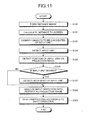
FIG. 11 is a flowchart illustrating a sequential processes from detection of an input operation with respect to a projection image by an operator through to performance of a process corresponding to the input operation by the respective functional components of thecontrol device 4 described above. Hereinafter, a summary of the process of thecontrol device 4 will be described following this flowchart. - First, in step S101, the distance
image forming unit 41 forms a distance image of the imaging region of thestereo camera 3 based on two images output from the twoimaging elements stereo camera 3. - In step S102, the input
unit detecting unit 43 calculates a distance from theprojector device 1 to thescreen 100, on which a projection image is projected, based on the distance image formed by the distanceimage forming unit 41 in step S101. - In step S103, the
candidate identifying unit 42 identifies objects to be candidates of the input unit among objects present in the imaging region of thestereo camera 3 using an image output from one of the twoimaging elements stereo camera 3. - In step S104, the input
unit detecting unit 43 identifies objects present in a region of a predetermined distance from the position of thescreen 100 using the distance to thescreen 100 calculated in step S102 as a reference, and among the identified objects, the inputunit detecting unit 43 detects, as the input unit, the object identified as the candidate of the input unit by thecandidate identifying unit 42 in step S103. - In step S105, the
position detecting unit 44 detects a position of the input unit, which has been detected by the inputunit detecting unit 43 in step S104, on the projection image. - In step S106, the
movement detecting unit 45 determines if the input unit, which has been detected by the inputunit detecting unit 43 in step S104, is moving on the projection image or not using a plurality of images sequentially output from one of the twoimaging elements stereo camera 3. And if the input unit is moving on the projection image (step S106: Yes), themovement detecting unit 45 detects a movement of the input unit by tracking the input unit through the plurality of images in step S107. On the other hand, if the input unit is not moving on the projection image (step S106: No), the process jumps to step S108 skipping the movement detection in step S107. - In step S108, the analyzing
unit 46 analyzes an input operation of the operator with respect to the projection image projected on thescreen 100 based on at least one of the position of the input unit detected by theposition detecting unit 44 in step S105 and the movement of the input unit detected by themovement detecting unit 45 in step S107. In step S109, a process with respect to the projection image is performed according to a content of the input operation analyzed by the analyzingunit 46 in step S108. - As described above, the
projector device 1 according to this embodiment detects an input operation of an operator with respect to a projection image using thestereo camera 3, and hence the input operation of the operator can be accurately detected. Specifically, with the use of the distance image of thestereo camera 3, a position in the depth direction (Z direction) that is a distance to an object can be detected as well as a position in an image plane (X and Y directions) as to objects present in the imaging region of thestereo camera 3. Therefore, among objects present in the imaging region of thestereo camera 3, only an object in a position close to thescreen 100 on which a projection image is projected can be detected as the input unit that performs an input operation with respect to the projection image. Then, based on the position of the detected input unit on the projection image and the movement thereof in X and Y directions, an input operation of an operator with respect to the projection image can be accurately detected. - Conventionally, a projector device provided with not a stereo camera but a monocular camera is known. A monocular camera cannot detect a distance to an object present in an imaging region thereof (depth), and a three-dimensional coordinate position of the object cannot be calculated. Therefore, in a technique described in Japanese Patent No.
3950837 projector device 1 according to this embodiment can write characters and pictures on a projection image by a finger of an operator, for example, without using a special pen or the like. In addition, theprojector device 1 according to this embodiment can appropriately detect various input operations, which are hard to be realized by an operation using such a special pen, including enlargement and reduction of a projection image, for example. - In addition, with a configuration of detecting a position and a movement of a finger of an operator or the like from an image captured by a monocular camera and analyzing an input operation with respect to a projection image, there is a possibility of a false detection of a finger or the like having a similar shape, if included as an image in the projection image, as an object to perform an input operation so as to perform a wrong process. On the contrary, with the use of the distance image of the
stereo camera 3, a finger projected on thescreen 100 as the projection image and a finger performing an input operation near thescreen 100 can be clearly distinguished, and hence a false detection as described above can be prevented. - Here, the distance image of the
stereo camera 3 has disadvantages of no color information, imprecise outline of an object in many cases, and the like. Therefore, it may be difficult to detect a finger of an operator only from the distance image depending on an individual difference of an operator performing an input operation with respect to the projection image or depending on a difference of a scene and conditions of an input operation. In such a case, the detection accuracy can be improved by analyzing an image output from one of theimaging elements stereo camera 3 so as to detect fingers present in the imaging region, and by identifying a finger present near thescreen 100 using the distance image as described above. - Meanwhile, many of projector devices are generally provided with an autofocus function for automatically focusing on the projection image upon startup, a trapezoidal correction function for correcting trapezoidal distortion of the projection image, and the like. In order to realize functions as described above, conventional projector devices are provided with various sensors. For example, it is known to measure a distance to a screen on which a projection image is projected by using an optical sensor described in Japanese Laid-open Patent Publication No.
2003-42733 2000-122617 - On the contrary, since the
projector device 1 according to this embodiment is provided with thestereo camera 3, the autofocus function and the trapezoidal correction function can be realized using thestereo camera 3. That means theprojector device 1 according to this embodiment can realize the auto focus function and the trapezoidal correction function by detecting a distance to thescreen 100 and an inclination of thescreen 100 with respect to theprojector device 1 by using the distance image of thestereo camera 3. Thus there is no need of separately providing an optical sensor for realizing the auto focus function, a plurality of distance sensors for realizing the trapezoidal correction function, or the like. Hereinafter, specific examples of the autofocus function and the trapezoidal correction function realized by theprojector device 1 according to this embodiment. - An autofocus operation of the
projector device 1 is performed as one of initial setting operations upon startup of theprojector device 1 under control of thecontrol device 4, for example. When theprojector device 1 is powered on, thecontrol device 4 firstly activates theprojection device 2, and supplies an image of an opening screen, which is previously stored in thestorage device 5 or the like, to theprojection device 2. Then, theprojection device 2 projects the projection image of the opening image on thescreen 100. Thecontrol device 4 also activates thestereo camera 3, and makes it start to image the imaging region including the projection image of the opening image projected on thescreen 100. The opening image includes a corporate logo and the like, for example. - The
imaging elements stereo camera 3 respectively output image signals of the imaging region, and the signals are converted to digital data to be input to thecontrol device 4. The control device 4 (distance image forming unit 41) forms a distance image using these images from thestereo camera 3, and from the distance image, thecontrol device 4 detects a distance to the logo included in the opening image, for example, so as to detect a distance from theprojector device 1 to thescreen 100. - Then, the
control device 4 sends a drive control signal to theprojection device 2 based on the detected distance to thescreen 100. The drive control signal is for moving theprojection lens 2a of theprojection device 2 in the optical axis direction. Theprojection device 2 moves theprojection lens 2a to the focal position corresponding to the drive control signal from thecontrol device 4. Thus, an in-focus projection image can be projected on thescreen 100. - Generally, a projector device unfortunately projects a screen with distortion called trapezoidal distortion (also called keystone distortion) when a projection angle of a projection image deviates with respect to the
screen 100. Therefore, conventionally, two distance sensors are arranged on a front surface of a projector device so as to calculate an inclination angle θ between the projector device and thescreen 100 based on distances to thescreen 100 measured by the two distance sensors. Then based on the calculated inclination angle, the trapezoidal distortion of a projected screen is conventionally corrected. -
FIG. 12 is a diagram schematically illustrating a conventional trapezoidal correction process. As illustrated inFIG. 12 , twodistance sensors projector device 200. At this time, an inclination angle θ between theprojector device 200 and thescreen 100 is expressed as the following Equation (2) where distance output values from the twodistance sensors screen 100 are indicated as D1 and D2.
- Such a conventional manner has following disadvantages. That is, inclinations only around X axis can be measured from the distance output values D1 and D2 of the two
distance sensors distance sensors projector device 200. Therefore, inclinations can be measured only in a narrow area no wider than the width of theprojector device 200 in thebigger screen 100, and thus inclinations of thescreen 100 as a whole cannot be detected. - In the
projector device 1 according to the embodiment, thestereo camera 3 is used to detect an inclination of thescreen 100 with respect to theprojector device 1 as described above. With the use of thestereo camera 3, an imaging region can be a wide area by designing thelenses stereo camera 3 to be wide, and hence distances in the wide area can be measured. For example, when a diagonal angle of view is set to 65 degrees, it is possible to measure distances in the whole area of thescreen 100 of 100 inches that is 2 meters away from theprojector device 1. Therefore, inclinations can be precisely detected in far wider area than a case where the inclination angle θ of thescreen 100 is detected using the twodistance sensors projector device 200 as illustrated inFIG. 12 . - In addition, since the
imaging elements stereo camera 3 are two-dimensional sensors, multiple focus points can be provided corresponding to the numbers of pixels of theimaging elements imaging elements FIG. 13 shows distance measurement results of the respective 80 × 80 focus points in shades corresponding to the distances. When thescreen 100 does not incline at all, and thus all distances in the surface thereof are equal to each other, the density in the surface is uniform as illustrated in (b) ofFIG. 13 . On the other hand, when thescreen 100 inclines to the left or right, the density is non-uniform corresponding to the inclination as illustrated in (a) or (c) ofFIG. 13 . - When the distance of each focus point in the surface of the
screen 100 is known as described above, an inclination angle θ of thescreen 100 with respect to theprojector device 1 can be calculated using the following Equation (3). In Equation (3), L1 is a distance from theprojector device 1 to the center of a projection image projected on thescreen 100, L2 is a distance from theprojector device 1 to an edge of the projection image projected on thescreen 100, and α is an angle of view of thelenses stereo camera 3.
- Although only the inclination in a horizontal plane of the
screen 100 is described here, the inclination in a vertiacal plane of thescreen 100 can be naturally detected in a similar way. In addition, since distances are measured at multiple focus points using thestereo camera 3, slightly uneven inclinations in the surface of thescreen 100 can be detected when such slightly uneven inclinations exist in the surface. Here, only detection of inclinations is described, but the trapezoidal distortion of a projection image can be accurately corrected similarly to the conventional manner when inclinations can be precisely detected. - In the
stereo camera 3 provided in theprojector device 1 according to this embodiment, twoimaging elements imaging element substrate 34 as described above. Such twoimaging elements multiple imaging elements 30 formed on asemiconductor wafer 50 by a well known semiconductor process along a dashed line border as illustrated inFIG. 14 , for example. - The
multiple imaging elements 30 on thesemiconductor wafer 50 has been patterned using a mask, and hence theimaging elements multiple imaging elements 30 are aligned with high accuracy so that pixel matrixes of theimaging elements semiconductor wafer 50 is an accurate plane, normals of theimaging elements imaging elements imaging elements stereo camera 3 provided with theimaging elements screen 100 and to an object that is present in the imaging region on the near side of thescreen 100 can be precisely detected. - In addition, the size of the
imaging elements stereo camera 3 may be much smaller comparing to the size (about 1/2.3 inch) of an imaging element used for a digital camera or the like. For example, a small imaging element of about 1/10 inch that is used for a camera module of a mobile phone can be used. - Generally, a small size imaging element cannot work well in dark places because a light amount entering in the element is small, which is a disadvantage thereof. However, the
stereo camera 3 provided in theprojector device 1 according to this embodiment ensures a sufficient light amount since it images thescreen 100 on which a projection image is projected. Therefore, even when a small size imaging element is used, sufficient performance can be provided, and the use of a small size imaging element enables to downsize thestereo camera 3. - Further, an imaging element for a camera module of a mobile phone is advantageous in cost since it is mass-produced, and an imaging element of VGA size (640 × 480 pixels) is especially inexpensive. Therefore, when two of multiple imaging elements of VGA size, for example, formed on the
semiconductor wafer 50 by a well known semiconductor process are integrally cut out, twoimaging elements imaging element substrate 34 as illustrated inFIG. 4B can be obtained at low cost. Thus, the cost of thestereo camera 3 can be also reduced. - In this embodiment, the
stereo camera 3 is described to have twoimaging elements stereo camera 3 may be configured to have three or more imaging elements. In this case, three or more imaging elements in line that are of multiple imaging elements formed on thesemiconductor wafer 50 may be integrally cut out, and the cut out imaging elements may be used as imaging elements of thestereo camera 3. With this configuration, a base line length D can be large when a distance between imaging elements at both ends of the three or more imaging elements in line is the base line length D. Therefore, the disparity Δ (= D × f/L) becomes large as can be understood from Equation (1) above, and hence distances can be measured with high accuracy. - In addition, in the
stereo camera 3 provided in theprojector device 1 according to this embodiment, thelenses imaging elements lens array 32 as described above. This is to prevent the twolenses lenses lenses - Since the
stereo camera 3, which is provided in theprojector device 1 according to this embodiment, is provided with theintegrated imaging elements integrated lenses lenses imaging elements projector device 1 according to this embodiment can accurately detect distances since thestereo camera 3 provided with theintegrated imaging elements integrated lenses projector device 1, and thus theprojector device 1 is stable with respect to heat and vibration. - In the
projector device 1 according to this embodiment, a characteristic functional configuration of thecontrol device 4 described above (refer toFIG. 5 ) can be realized by the CPU of thecontrol device 4 running a control program, as an example. In this case, the control program run by the CPU of thecontrol device 4 may be previously embedded and provided in a ROM included in thestorage device 5, for example. - The control program run by the CPU of the
control device 4 may be configured as a file in a form that can be installed or run, and recorded and provided in a computer readable recording medium such as a CD-ROM, a flexible disk, a CD-R, a DVD, or the like. In addition, the control program run by the CPU of thecontrol device 4 may be configured to be stored in a computer connected to a network such as the Internet and to be provided by downloading via the network. Further, the control program run by the CPU of thecontrol device 4 may be configured to be provided or distributed via a network such as the Internet. - The control program run by the CPU of the
control device 4 may have a module configuration including the distanceimage forming unit 41, thecandidate identifying unit 42, the inputunit detecting unit 43, theposition detecting unit 44, themovement detecting unit 45, the analyzingunit 46, and the image processing unit 47, for example. The CPU (processor) as an actual hardware reads the control program from the ROM and runs the control program, whereby the respective units described above are loaded on a primary storage device (RAM, for example) so that the distanceimage forming unit 41, thecandidate identifying unit 42, the inputunit detecting unit 43, theposition detecting unit 44, themovement detecting unit 45, the analyzingunit 46, and the image processing unit 47 are formed on the primary storage device. - Although a specific embodiment of the present invention is described above, the present invention is not limited to the embodiment described above as is but may be realized with changes of components when implemented without departing from the scope of the invention. For example, a distance image is formed by the
control device 4 in the embodiment described above, but a distance image may be formed by thestereo camera 3 by providing a DSP or the like for processing digital signals on thestereo camera 3, and then the formed distance image may be sent to thecontrol device 4. In addition, an input operation of an operator with respect to a projection image is detected by theprojector device 1 in the embodiment described above, but a distance image of thestereo camera 3 may be sent to thePC 101, and then thePC 101 may detect an input operation of an operator with respect to a projection image. - According to the embodiments, distance information of an object that is present in an imaging region including a projection surface of a projection image is acquired; the object is recognized as an input unit performing an input operation to the projection image if the object is present in an area of a predetermined distant from a projection surface; and the input operation to the projection image is analyzed based on at least one of a position and a movement of the input unit, thereby having an effect that various functions can be realized by detecting an input to the projection image without using a dedicated input device.
- Although the invention has been described with respect to specific embodiments for a complete and clear disclosure, the appended claims are not to be thus limited but are to be construed as embodying all modifications and alternative constructions that may occur to one skilled in the art that fairly fall within the basic teaching herein set forth.
Claims (5)
- A projector device (1) comprising:a projection unit (2) configured to project a projection image on a projection surface (100);an image capturing unit configured to capture an image of an imaging region including the projection surface by a plurality of imaging elements (30a, 30b);a distance acquiring unit (41) configured to acquire distance information indicating a distance between the image capturing unit (3) and an object present in the imaging region based on a plurality of images output from the plurality of imaging elements (30a, 30b);an input unit detecting unit (43) configured to detect, based on the distance information, the object as an input unit performing an input operation with respect to the projection image when the object is present in a reqion of a predetermined distance from the projection surface (100); andan analyzing unit (46) configured to analyze the input operation with respect to the projection image based on at least one of a position and a movement of the input unit on the projection image.
- The projector device (1) according to claim 1, further comprising:a storage unit (5) configured to store therein a feature value of an object to be a candidate of the input unit; anda candidate identifying unit (42) configured to identify the object present in the imaging region as the object to be the candidate of the input unit based on an image output from at least one of the plurality of imaging elements (30a, 30b) and the feature value, whereinthe input unit detecting unit (43) detects, as the input unit, the object identified by the candidate identifying unit (42) and present in the region of the predetermined distance from the projection surface (100).
- The projector device (1) according to claim 1 or 2 further comprising a movement detecting unit configured to detect a movement of the input unit based on the plurality of images sequentially output from at least one of the plurality of imaging elements (30a, 30b), wherein
the analyzing unit (46) analyzes the input operation with respect to the projection image based on the movement of the input unit detected by the movement detecting unit. - The projector device (1) according to any one of claims 1 to 3, wherein
the image capturing unit (3) includes a plurality of lenses (32a, 32b) respectively forming images of the imaging region on the plurality of imaging elements (30a, 30b),
the plurality of imaging elements (30a, 30b) are integrally provided on one substrate, and
the plurality of lenses (32a, 32b) are integrally formed and positioned to face the plurality of imaging elements (30a, 30b), respectively. - An operation detecting method executed in a projector device that includes a projection unit (2) configured to project a projection image on a projection surface (100) and an image capturing unit (3) configured to capture an image of an imaging region including the projection surface (100) by a plurality of imaging elements (30a, 30b), the method comprising:acquiring distance information indicating a distance between the image capturing unit (3) and an object present in the imaging region based on a plurality of images output from the plurality of imaging elements (30a, 30b);detecting, based on the distance information, the object as an input unit performing an input operation with respect to the projection image when the object is present in a region of a predetermined distance from the projection surface (100); andanalyzing the input operation with respect to the projection image based on at least one of a position and a movement of the input unit on the projection image.
Applications Claiming Priority (1)
| Application Number | Priority Date | Filing Date | Title |
|---|---|---|---|
| JP2011200832A JP2013061552A (en) | 2011-09-14 | 2011-09-14 | Projector device and operation detection method |
Publications (2)
| Publication Number | Publication Date |
|---|---|
| EP2571257A1 true EP2571257A1 (en) | 2013-03-20 |
| EP2571257B1 EP2571257B1 (en) | 2015-10-21 |
Family
ID=46851827
Family Applications (1)
| Application Number | Title | Priority Date | Filing Date |
|---|---|---|---|
| EP12182087.2A Active EP2571257B1 (en) | 2011-09-14 | 2012-08-28 | Projector device and operation detecting method |
Country Status (4)
| Country | Link |
|---|---|
| US (1) | US20130063401A1 (en) |
| EP (1) | EP2571257B1 (en) |
| JP (1) | JP2013061552A (en) |
| CN (1) | CN103002239A (en) |
Cited By (1)
| Publication number | Priority date | Publication date | Assignee | Title |
|---|---|---|---|---|
| US11780097B2 (en) | 2018-12-06 | 2023-10-10 | Sony Group Corporation | Information processing apparatus and method for processing information |
Families Citing this family (32)
| Publication number | Priority date | Publication date | Assignee | Title |
|---|---|---|---|---|
| KR101627634B1 (en) * | 2011-12-26 | 2016-06-08 | 한국전자통신연구원 | Projector image correction device and method |
| JP6167511B2 (en) * | 2012-12-04 | 2017-07-26 | セイコーエプソン株式会社 | Document camera and document camera control method |
| DE102013211904A1 (en) * | 2013-06-24 | 2014-12-24 | Robert Bosch Gmbh | Method and device for determining gestures in the beam area of a projector |
| JP6356235B2 (en) * | 2013-06-26 | 2018-07-11 | オセ−テクノロジーズ・ベー・ヴエーOce’−Nederland Besloten Vennootshap | Method for generating prints on a flatbed printer, apparatus therefor and computer program therefor |
| JP2015046686A (en) * | 2013-08-27 | 2015-03-12 | 株式会社リコー | Display system, information terminal, transmission control program, and transmission control method |
| JP5802247B2 (en) * | 2013-09-25 | 2015-10-28 | 株式会社東芝 | Information processing device |
| JP6218590B2 (en) * | 2013-12-18 | 2017-10-25 | キヤノン株式会社 | Coordinate input device and control method thereof |
| TWI518574B (en) * | 2013-12-25 | 2016-01-21 | 光峰科技股份有限公司 | Interactive display system and input device thereof |
| US20160349926A1 (en) * | 2014-01-10 | 2016-12-01 | Nec Corporation | Interface device, portable device, control device and module |
| JP2015212927A (en) * | 2014-04-17 | 2015-11-26 | 株式会社リコー | Input operation detection device, image display device including input operation detection device, and projector system |
| JP6341755B2 (en) * | 2014-05-26 | 2018-06-13 | キヤノン株式会社 | Information processing apparatus, method, program, and recording medium |
| JP2016001354A (en) * | 2014-06-11 | 2016-01-07 | パナソニックIpマネジメント株式会社 | Projection area setting device, and work detection system using the projection area setting device |
| JP6350175B2 (en) * | 2014-09-26 | 2018-07-04 | セイコーエプソン株式会社 | POSITION DETECTION DEVICE, PROJECTOR, AND POSITION DETECTION METHOD |
| JP2016071864A (en) * | 2014-09-26 | 2016-05-09 | パナソニックIpマネジメント株式会社 | Projector apparatus |
| JP6405836B2 (en) * | 2014-09-26 | 2018-10-17 | セイコーエプソン株式会社 | POSITION DETECTION DEVICE, PROJECTOR, AND POSITION DETECTION METHOD |
| JP2016114963A (en) | 2014-12-11 | 2016-06-23 | 株式会社リコー | Input operation detection device, projector device, electronic blackboard device, digital signage device, and projector system |
| CN105227882B (en) * | 2015-09-25 | 2019-01-15 | 联想(北京)有限公司 | A kind of display methods and corresponding intrument |
| JP6467516B2 (en) * | 2015-09-29 | 2019-02-13 | 富士フイルム株式会社 | Projector device with distance image acquisition device and projection method |
| CN106612422B (en) * | 2015-12-31 | 2018-08-28 | 北京一数科技有限公司 | A kind of projection correction's method and device |
| JP6878816B2 (en) * | 2016-01-20 | 2021-06-02 | セイコーエプソン株式会社 | projector |
| CN106200225A (en) * | 2016-09-21 | 2016-12-07 | 北京小米移动软件有限公司 | The trapezoidal distortion correction method of projector and device |
| JP6798270B2 (en) * | 2016-11-21 | 2020-12-09 | セイコーエプソン株式会社 | Imaging lens system, imaging device and projector |
| JPWO2018167999A1 (en) * | 2017-03-17 | 2020-01-16 | パナソニックIpマネジメント株式会社 | Projector and projector system |
| CN108664153A (en) * | 2017-04-02 | 2018-10-16 | 田雪松 | digital pen |
| US20190096297A1 (en) * | 2017-09-28 | 2019-03-28 | Benjamin Cary | Vehicle mounted image projection system |
| CN108307164A (en) * | 2017-12-30 | 2018-07-20 | 神画科技(深圳)有限公司 | A kind of control method and control system of projecting apparatus |
| JP6675086B2 (en) * | 2018-08-21 | 2020-04-01 | パナソニックIpマネジメント株式会社 | Work detection system |
| JP6733789B2 (en) * | 2019-07-31 | 2020-08-05 | 富士通株式会社 | Input device, input operation detection method, and input operation detection computer program |
| JP2021026609A (en) | 2019-08-07 | 2021-02-22 | セイコーエプソン株式会社 | Projection system, position detection system, and method for controlling position detection system |
| JP2021033554A (en) | 2019-08-22 | 2021-03-01 | セイコーエプソン株式会社 | Projection system, position detection system, and position detection method |
| KR20210123059A (en) * | 2020-04-02 | 2021-10-13 | 삼성전자주식회사 | Image projecting apparatus and controlling method thereof |
| CN115883799A (en) * | 2021-09-29 | 2023-03-31 | 中强光电股份有限公司 | Projector and projection method |
Citations (6)
| Publication number | Priority date | Publication date | Assignee | Title |
|---|---|---|---|---|
| JP2000122617A (en) | 1998-10-12 | 2000-04-28 | Toshiba Corp | Trapezoidal distortion correction device |
| JP2003042733A (en) | 2001-08-03 | 2003-02-13 | Mitsutoyo Corp | Optical shape sensor for extraction of distance, etc., to measuring object |
| EP1689172A1 (en) * | 2001-06-05 | 2006-08-09 | Reactrix Systems, Inc. | Interactive video display system |
| JP3950837B2 (en) | 2003-10-21 | 2007-08-01 | Necディスプレイソリューションズ株式会社 | Projector, electronic blackboard system using projector, and indication position acquisition method |
| JP2008090807A (en) * | 2006-09-06 | 2008-04-17 | National Institute Of Advanced Industrial & Technology | Compact mobile terminal |
| US20090168027A1 (en) * | 2007-12-28 | 2009-07-02 | Motorola, Inc. | Projector system employing depth perception to detect speaker position and gestures |
Family Cites Families (2)
| Publication number | Priority date | Publication date | Assignee | Title |
|---|---|---|---|---|
| US8035612B2 (en) * | 2002-05-28 | 2011-10-11 | Intellectual Ventures Holding 67 Llc | Self-contained interactive video display system |
| US7259747B2 (en) * | 2001-06-05 | 2007-08-21 | Reactrix Systems, Inc. | Interactive video display system |
-
2011
- 2011-09-14 JP JP2011200832A patent/JP2013061552A/en active Pending
-
2012
- 2012-08-15 US US13/586,145 patent/US20130063401A1/en not_active Abandoned
- 2012-08-28 EP EP12182087.2A patent/EP2571257B1/en active Active
- 2012-09-12 CN CN2012103369911A patent/CN103002239A/en active Pending
Patent Citations (6)
| Publication number | Priority date | Publication date | Assignee | Title |
|---|---|---|---|---|
| JP2000122617A (en) | 1998-10-12 | 2000-04-28 | Toshiba Corp | Trapezoidal distortion correction device |
| EP1689172A1 (en) * | 2001-06-05 | 2006-08-09 | Reactrix Systems, Inc. | Interactive video display system |
| JP2003042733A (en) | 2001-08-03 | 2003-02-13 | Mitsutoyo Corp | Optical shape sensor for extraction of distance, etc., to measuring object |
| JP3950837B2 (en) | 2003-10-21 | 2007-08-01 | Necディスプレイソリューションズ株式会社 | Projector, electronic blackboard system using projector, and indication position acquisition method |
| JP2008090807A (en) * | 2006-09-06 | 2008-04-17 | National Institute Of Advanced Industrial & Technology | Compact mobile terminal |
| US20090168027A1 (en) * | 2007-12-28 | 2009-07-02 | Motorola, Inc. | Projector system employing depth perception to detect speaker position and gestures |
Cited By (1)
| Publication number | Priority date | Publication date | Assignee | Title |
|---|---|---|---|---|
| US11780097B2 (en) | 2018-12-06 | 2023-10-10 | Sony Group Corporation | Information processing apparatus and method for processing information |
Also Published As
| Publication number | Publication date |
|---|---|
| US20130063401A1 (en) | 2013-03-14 |
| JP2013061552A (en) | 2013-04-04 |
| EP2571257B1 (en) | 2015-10-21 |
| CN103002239A (en) | 2013-03-27 |
Similar Documents
| Publication | Publication Date | Title |
|---|---|---|
| EP2571257B1 (en) | Projector device and operation detecting method | |
| US10564392B2 (en) | Imaging apparatus and focus control method | |
| US11652975B2 (en) | Field calibration of stereo cameras with a projector | |
| TWI585436B (en) | Method and apparatus for measuring depth information | |
| US10091489B2 (en) | Image capturing device, image processing method, and recording medium | |
| US10578426B2 (en) | Object measurement apparatus and object measurement method | |
| CN108700408B (en) | Three-dimensional shape data and texture information generation system, method and shooting control method | |
| EP1343332A2 (en) | Stereoscopic image characteristics examination system | |
| US9134117B2 (en) | Distance measuring system and distance measuring method | |
| JP5951043B2 (en) | Image measuring device | |
| US20210150744A1 (en) | System and method for hybrid depth estimation | |
| JP2012015642A (en) | Imaging device | |
| US8699757B2 (en) | Software embodied on a non-transitory storage media for distance measurement using speckle pattern | |
| US9158183B2 (en) | Stereoscopic image generating device and stereoscopic image generating method | |
| JP2011149931A (en) | Distance image acquisition device | |
| US10802143B2 (en) | Distance measurement device, deriving method for distance measurement, and deriving program for distance measurement | |
| JP2016217944A (en) | Measurement device and measurement method | |
| US10641896B2 (en) | Distance measurement device, distance measurement method, and distance measurement program | |
| US10353070B2 (en) | Distance measurement device, distance measurement method, and distance measurement program | |
| US20180328719A1 (en) | Information processing device, information processing method, and program | |
| US20140176706A1 (en) | Range-finding method and computer program product | |
| US11181359B2 (en) | Information processing device, information processing method, and program | |
| WO2018161322A1 (en) | Depth-based image processing method, processing device and electronic device | |
| JP2013217847A (en) | Imaging apparatus, length measurement method, and program |
Legal Events
| Date | Code | Title | Description |
|---|---|---|---|
| PUAI | Public reference made under article 153(3) epc to a published international application that has entered the european phase |
Free format text: ORIGINAL CODE: 0009012 |
|
| 17P | Request for examination filed |
Effective date: 20120828 |
|
| AK | Designated contracting states |
Kind code of ref document: A1 Designated state(s): AL AT BE BG CH CY CZ DE DK EE ES FI FR GB GR HR HU IE IS IT LI LT LU LV MC MK MT NL NO PL PT RO RS SE SI SK SM TR |
|
| AX | Request for extension of the european patent |
Extension state: BA ME |
|
| 17Q | First examination report despatched |
Effective date: 20140204 |
|
| REG | Reference to a national code |
Ref country code: DE Ref legal event code: R079 Ref document number: 602012011743 Country of ref document: DE Free format text: PREVIOUS MAIN CLASS: H04N0005740000 Ipc: G06F0003048800 |
|
| GRAP | Despatch of communication of intention to grant a patent |
Free format text: ORIGINAL CODE: EPIDOSNIGR1 |
|
| RIC1 | Information provided on ipc code assigned before grant |
Ipc: G06F 3/0488 20130101AFI20150417BHEP Ipc: H04N 9/31 20060101ALI20150417BHEP Ipc: G06F 3/042 20060101ALI20150417BHEP |
|
| INTG | Intention to grant announced |
Effective date: 20150511 |
|
| GRAS | Grant fee paid |
Free format text: ORIGINAL CODE: EPIDOSNIGR3 |
|
| GRAA | (expected) grant |
Free format text: ORIGINAL CODE: 0009210 |
|
| AK | Designated contracting states |
Kind code of ref document: B1 Designated state(s): AL AT BE BG CH CY CZ DE DK EE ES FI FR GB GR HR HU IE IS IT LI LT LU LV MC MK MT NL NO PL PT RO RS SE SI SK SM TR |
|
| REG | Reference to a national code |
Ref country code: GB Ref legal event code: FG4D Ref country code: NL Ref legal event code: MP Effective date: 20151021 |
|
| REG | Reference to a national code |
Ref country code: CH Ref legal event code: EP |
|
| REG | Reference to a national code |
Ref country code: AT Ref legal event code: REF Ref document number: 756986 Country of ref document: AT Kind code of ref document: T Effective date: 20151115 |
|
| REG | Reference to a national code |
Ref country code: IE Ref legal event code: FG4D |
|
| REG | Reference to a national code |
Ref country code: DE Ref legal event code: R096 Ref document number: 602012011743 Country of ref document: DE |
|
| REG | Reference to a national code |
Ref country code: LT Ref legal event code: MG4D |
|
| REG | Reference to a national code |
Ref country code: AT Ref legal event code: MK05 Ref document number: 756986 Country of ref document: AT Kind code of ref document: T Effective date: 20151021 |
|
| PG25 | Lapsed in a contracting state [announced via postgrant information from national office to epo] |
Ref country code: NO Free format text: LAPSE BECAUSE OF FAILURE TO SUBMIT A TRANSLATION OF THE DESCRIPTION OR TO PAY THE FEE WITHIN THE PRESCRIBED TIME-LIMIT Effective date: 20160121 Ref country code: IT Free format text: LAPSE BECAUSE OF FAILURE TO SUBMIT A TRANSLATION OF THE DESCRIPTION OR TO PAY THE FEE WITHIN THE PRESCRIBED TIME-LIMIT Effective date: 20151021 Ref country code: HR Free format text: LAPSE BECAUSE OF FAILURE TO SUBMIT A TRANSLATION OF THE DESCRIPTION OR TO PAY THE FEE WITHIN THE PRESCRIBED TIME-LIMIT Effective date: 20151021 Ref country code: LT Free format text: LAPSE BECAUSE OF FAILURE TO SUBMIT A TRANSLATION OF THE DESCRIPTION OR TO PAY THE FEE WITHIN THE PRESCRIBED TIME-LIMIT Effective date: 20151021 Ref country code: ES Free format text: LAPSE BECAUSE OF FAILURE TO SUBMIT A TRANSLATION OF THE DESCRIPTION OR TO PAY THE FEE WITHIN THE PRESCRIBED TIME-LIMIT Effective date: 20151021 Ref country code: NL Free format text: LAPSE BECAUSE OF FAILURE TO SUBMIT A TRANSLATION OF THE DESCRIPTION OR TO PAY THE FEE WITHIN THE PRESCRIBED TIME-LIMIT Effective date: 20151021 Ref country code: IS Free format text: LAPSE BECAUSE OF FAILURE TO SUBMIT A TRANSLATION OF THE DESCRIPTION OR TO PAY THE FEE WITHIN THE PRESCRIBED TIME-LIMIT Effective date: 20160221 |
|
| PG25 | Lapsed in a contracting state [announced via postgrant information from national office to epo] |
Ref country code: SE Free format text: LAPSE BECAUSE OF FAILURE TO SUBMIT A TRANSLATION OF THE DESCRIPTION OR TO PAY THE FEE WITHIN THE PRESCRIBED TIME-LIMIT Effective date: 20151021 Ref country code: LV Free format text: LAPSE BECAUSE OF FAILURE TO SUBMIT A TRANSLATION OF THE DESCRIPTION OR TO PAY THE FEE WITHIN THE PRESCRIBED TIME-LIMIT Effective date: 20151021 Ref country code: RS Free format text: LAPSE BECAUSE OF FAILURE TO SUBMIT A TRANSLATION OF THE DESCRIPTION OR TO PAY THE FEE WITHIN THE PRESCRIBED TIME-LIMIT Effective date: 20151021 Ref country code: PT Free format text: LAPSE BECAUSE OF FAILURE TO SUBMIT A TRANSLATION OF THE DESCRIPTION OR TO PAY THE FEE WITHIN THE PRESCRIBED TIME-LIMIT Effective date: 20160222 Ref country code: GR Free format text: LAPSE BECAUSE OF FAILURE TO SUBMIT A TRANSLATION OF THE DESCRIPTION OR TO PAY THE FEE WITHIN THE PRESCRIBED TIME-LIMIT Effective date: 20160122 Ref country code: PL Free format text: LAPSE BECAUSE OF FAILURE TO SUBMIT A TRANSLATION OF THE DESCRIPTION OR TO PAY THE FEE WITHIN THE PRESCRIBED TIME-LIMIT Effective date: 20151021 Ref country code: AT Free format text: LAPSE BECAUSE OF FAILURE TO SUBMIT A TRANSLATION OF THE DESCRIPTION OR TO PAY THE FEE WITHIN THE PRESCRIBED TIME-LIMIT Effective date: 20151021 Ref country code: FI Free format text: LAPSE BECAUSE OF FAILURE TO SUBMIT A TRANSLATION OF THE DESCRIPTION OR TO PAY THE FEE WITHIN THE PRESCRIBED TIME-LIMIT Effective date: 20151021 |
|
| REG | Reference to a national code |
Ref country code: DE Ref legal event code: R097 Ref document number: 602012011743 Country of ref document: DE |
|
| PG25 | Lapsed in a contracting state [announced via postgrant information from national office to epo] |
Ref country code: CZ Free format text: LAPSE BECAUSE OF FAILURE TO SUBMIT A TRANSLATION OF THE DESCRIPTION OR TO PAY THE FEE WITHIN THE PRESCRIBED TIME-LIMIT Effective date: 20151021 |
|
| REG | Reference to a national code |
Ref country code: FR Ref legal event code: PLFP Year of fee payment: 5 |
|
| PLBE | No opposition filed within time limit |
Free format text: ORIGINAL CODE: 0009261 |
|
| STAA | Information on the status of an ep patent application or granted ep patent |
Free format text: STATUS: NO OPPOSITION FILED WITHIN TIME LIMIT |
|
| PG25 | Lapsed in a contracting state [announced via postgrant information from national office to epo] |
Ref country code: SK Free format text: LAPSE BECAUSE OF FAILURE TO SUBMIT A TRANSLATION OF THE DESCRIPTION OR TO PAY THE FEE WITHIN THE PRESCRIBED TIME-LIMIT Effective date: 20151021 Ref country code: DK Free format text: LAPSE BECAUSE OF FAILURE TO SUBMIT A TRANSLATION OF THE DESCRIPTION OR TO PAY THE FEE WITHIN THE PRESCRIBED TIME-LIMIT Effective date: 20151021 Ref country code: SM Free format text: LAPSE BECAUSE OF FAILURE TO SUBMIT A TRANSLATION OF THE DESCRIPTION OR TO PAY THE FEE WITHIN THE PRESCRIBED TIME-LIMIT Effective date: 20151021 Ref country code: RO Free format text: LAPSE BECAUSE OF FAILURE TO SUBMIT A TRANSLATION OF THE DESCRIPTION OR TO PAY THE FEE WITHIN THE PRESCRIBED TIME-LIMIT Effective date: 20151021 Ref country code: EE Free format text: LAPSE BECAUSE OF FAILURE TO SUBMIT A TRANSLATION OF THE DESCRIPTION OR TO PAY THE FEE WITHIN THE PRESCRIBED TIME-LIMIT Effective date: 20151021 |
|
| 26N | No opposition filed |
Effective date: 20160722 |
|
| PG25 | Lapsed in a contracting state [announced via postgrant information from national office to epo] |
Ref country code: SI Free format text: LAPSE BECAUSE OF FAILURE TO SUBMIT A TRANSLATION OF THE DESCRIPTION OR TO PAY THE FEE WITHIN THE PRESCRIBED TIME-LIMIT Effective date: 20151021 |
|
| PG25 | Lapsed in a contracting state [announced via postgrant information from national office to epo] |
Ref country code: BE Free format text: LAPSE BECAUSE OF FAILURE TO SUBMIT A TRANSLATION OF THE DESCRIPTION OR TO PAY THE FEE WITHIN THE PRESCRIBED TIME-LIMIT Effective date: 20151021 |
|
| PG25 | Lapsed in a contracting state [announced via postgrant information from national office to epo] |
Ref country code: MC Free format text: LAPSE BECAUSE OF FAILURE TO SUBMIT A TRANSLATION OF THE DESCRIPTION OR TO PAY THE FEE WITHIN THE PRESCRIBED TIME-LIMIT Effective date: 20151021 |
|
| REG | Reference to a national code |
Ref country code: CH Ref legal event code: PL |
|
| PG25 | Lapsed in a contracting state [announced via postgrant information from national office to epo] |
Ref country code: LI Free format text: LAPSE BECAUSE OF NON-PAYMENT OF DUE FEES Effective date: 20160831 Ref country code: CH Free format text: LAPSE BECAUSE OF NON-PAYMENT OF DUE FEES Effective date: 20160831 |
|
| REG | Reference to a national code |
Ref country code: IE Ref legal event code: MM4A |
|
| PG25 | Lapsed in a contracting state [announced via postgrant information from national office to epo] |
Ref country code: IE Free format text: LAPSE BECAUSE OF NON-PAYMENT OF DUE FEES Effective date: 20160828 |
|
| REG | Reference to a national code |
Ref country code: FR Ref legal event code: PLFP Year of fee payment: 6 |
|
| PG25 | Lapsed in a contracting state [announced via postgrant information from national office to epo] |
Ref country code: LU Free format text: LAPSE BECAUSE OF NON-PAYMENT OF DUE FEES Effective date: 20160828 |
|
| PG25 | Lapsed in a contracting state [announced via postgrant information from national office to epo] |
Ref country code: CY Free format text: LAPSE BECAUSE OF FAILURE TO SUBMIT A TRANSLATION OF THE DESCRIPTION OR TO PAY THE FEE WITHIN THE PRESCRIBED TIME-LIMIT Effective date: 20151021 Ref country code: HU Free format text: LAPSE BECAUSE OF FAILURE TO SUBMIT A TRANSLATION OF THE DESCRIPTION OR TO PAY THE FEE WITHIN THE PRESCRIBED TIME-LIMIT; INVALID AB INITIO Effective date: 20120828 |
|
| PG25 | Lapsed in a contracting state [announced via postgrant information from national office to epo] |
Ref country code: TR Free format text: LAPSE BECAUSE OF FAILURE TO SUBMIT A TRANSLATION OF THE DESCRIPTION OR TO PAY THE FEE WITHIN THE PRESCRIBED TIME-LIMIT Effective date: 20151021 Ref country code: MK Free format text: LAPSE BECAUSE OF FAILURE TO SUBMIT A TRANSLATION OF THE DESCRIPTION OR TO PAY THE FEE WITHIN THE PRESCRIBED TIME-LIMIT Effective date: 20151021 Ref country code: MT Free format text: LAPSE BECAUSE OF NON-PAYMENT OF DUE FEES Effective date: 20160831 |
|
| PG25 | Lapsed in a contracting state [announced via postgrant information from national office to epo] |
Ref country code: BG Free format text: LAPSE BECAUSE OF FAILURE TO SUBMIT A TRANSLATION OF THE DESCRIPTION OR TO PAY THE FEE WITHIN THE PRESCRIBED TIME-LIMIT Effective date: 20151021 |
|
| REG | Reference to a national code |
Ref country code: FR Ref legal event code: PLFP Year of fee payment: 7 |
|
| PG25 | Lapsed in a contracting state [announced via postgrant information from national office to epo] |
Ref country code: AL Free format text: LAPSE BECAUSE OF FAILURE TO SUBMIT A TRANSLATION OF THE DESCRIPTION OR TO PAY THE FEE WITHIN THE PRESCRIBED TIME-LIMIT Effective date: 20151021 |
|
| PGFP | Annual fee paid to national office [announced via postgrant information from national office to epo] |
Ref country code: DE Payment date: 20200819 Year of fee payment: 9 Ref country code: FR Payment date: 20200821 Year of fee payment: 9 |
|
| REG | Reference to a national code |
Ref country code: DE Ref legal event code: R119 Ref document number: 602012011743 Country of ref document: DE |
|
| PG25 | Lapsed in a contracting state [announced via postgrant information from national office to epo] |
Ref country code: FR Free format text: LAPSE BECAUSE OF NON-PAYMENT OF DUE FEES Effective date: 20210831 Ref country code: DE Free format text: LAPSE BECAUSE OF NON-PAYMENT OF DUE FEES Effective date: 20220301 |
|
| PGFP | Annual fee paid to national office [announced via postgrant information from national office to epo] |
Ref country code: GB Payment date: 20230822 Year of fee payment: 12 |