EP2570868A1 - Part for a clockwork, clockwork and timepiece - Google Patents
Part for a clockwork, clockwork and timepiece Download PDFInfo
- Publication number
- EP2570868A1 EP2570868A1 EP11007420A EP11007420A EP2570868A1 EP 2570868 A1 EP2570868 A1 EP 2570868A1 EP 11007420 A EP11007420 A EP 11007420A EP 11007420 A EP11007420 A EP 11007420A EP 2570868 A1 EP2570868 A1 EP 2570868A1
- Authority
- EP
- European Patent Office
- Prior art keywords
- plate
- spiral
- anchor
- movement
- piece assembly
- Prior art date
- Legal status (The legal status is an assumption and is not a legal conclusion. Google has not performed a legal analysis and makes no representation as to the accuracy of the status listed.)
- Granted
Links
- 210000003423 ankle Anatomy 0.000 claims abstract description 10
- 238000010276 construction Methods 0.000 description 6
- 238000005530 etching Methods 0.000 description 5
- BASFCYQUMIYNBI-UHFFFAOYSA-N platinum Chemical compound [Pt] BASFCYQUMIYNBI-UHFFFAOYSA-N 0.000 description 5
- 230000007935 neutral effect Effects 0.000 description 4
- 239000000758 substrate Substances 0.000 description 4
- 238000004519 manufacturing process Methods 0.000 description 2
- 238000000034 method Methods 0.000 description 2
- 229910052697 platinum Inorganic materials 0.000 description 2
- 230000001105 regulatory effect Effects 0.000 description 2
- 229910052710 silicon Inorganic materials 0.000 description 2
- 239000010703 silicon Substances 0.000 description 2
- 241000287828 Gallus gallus Species 0.000 description 1
- 230000000703 anti-shock Effects 0.000 description 1
- 230000001186 cumulative effect Effects 0.000 description 1
- 239000012212 insulator Substances 0.000 description 1
- 238000003754 machining Methods 0.000 description 1
- 239000003550 marker Substances 0.000 description 1
- 229910021421 monocrystalline silicon Inorganic materials 0.000 description 1
- 210000000056 organ Anatomy 0.000 description 1
Images


Classifications
-
- G—PHYSICS
- G04—HOROLOGY
- G04B—MECHANICALLY-DRIVEN CLOCKS OR WATCHES; MECHANICAL PARTS OF CLOCKS OR WATCHES IN GENERAL; TIME PIECES USING THE POSITION OF THE SUN, MOON OR STARS
- G04B15/00—Escapements
- G04B15/06—Free escapements
- G04B15/08—Lever escapements
-
- G—PHYSICS
- G04—HOROLOGY
- G04B—MECHANICALLY-DRIVEN CLOCKS OR WATCHES; MECHANICAL PARTS OF CLOCKS OR WATCHES IN GENERAL; TIME PIECES USING THE POSITION OF THE SUN, MOON OR STARS
- G04B17/00—Mechanisms for stabilising frequency
- G04B17/04—Oscillators acting by spring tension
- G04B17/06—Oscillators with hairsprings, e.g. balance
-
- G—PHYSICS
- G04—HOROLOGY
- G04B—MECHANICALLY-DRIVEN CLOCKS OR WATCHES; MECHANICAL PARTS OF CLOCKS OR WATCHES IN GENERAL; TIME PIECES USING THE POSITION OF THE SUN, MOON OR STARS
- G04B17/00—Mechanisms for stabilising frequency
- G04B17/32—Component parts or constructional details, e.g. collet, stud, virole or piton
Definitions
- the present invention relates to a watch movement comprising a plate, an anchor bridge and a cock on which are pivoted respectively a balance shaft and an anchor; this movement comprising a balance wheel, a spiral secured to a ferrule, a large plate carrying an ankle and a small plate with a notch.
- the large tray and the small tray are separate elements, separated from each other which are each mounted separately on the balance shaft.
- the document EP 2 322 996 proposes to provide the ferrule of the spiral of a protrusion extending parallel to the axis of the spiral, crossing the balance and cooperating with the fork of an anchor.
- This protrusion coming from a workpiece with the hairspring and serving as ankle allows a perfect positioning between the ankle, the ferrule and the hairspring.
- This construction reduces by one unit the number of parts of the assembly but does not make it possible to suppress the setting to the reference.
- the object of the present invention is to further limit the number of parts required for a balance spring-type regulating member cooperating with an escapement anchor.
- Another object of the present invention is to suppress the setting operation when setting the balance sprung balance in the movement.
- Yet another object of the invention is to facilitate the introduction of the sprung balance in the movement by reducing the mounting operations.
- the object of the invention is to reduce as much as possible the overall height of the sprung balance and the large and small trays without reducing the safety distances necessary for the smooth operation of the sprung balance and the exhaust of the movement.
- the present invention thus relates to a watch movement comprising a plate, an anchor bridge and a cock on which are pivoted respectively a balance shaft and an anchor; this movement comprising a balance wheel, a spiral secured to a ferrule, a large plate carrying an ankle and a small plate with a notch which is distinguished by the fact that the spiral and its ferrule, the large plate and its ankle and the small plate form a monobloc assembly.
- this one-piece assembly may comprise an elastic clamp for fixing it to the axis of the balance.
- the end of the outer turn of the hairspring is integrally connected to a fixed part of the movement, in particular by means of a pin and its clamp.
- the present invention also relates to a timepiece comprising a movement in which the spiral and its ferrule, the large plate and its ankle as well as the small plate form a one-piece assembly that may include an elastic clip for its attachment to the balance shaft.
- the present invention also relates to a piece for a watch movement constituted by a one-piece assembly comprising a hairspring and its ferrule, a large plate and ankle and a small plate.
- the first embodiment illustrated in Figures 1 and 2 of the watch movement comprises a plate 1, an anchor bridge 2 fixed on the plate 1 and a cock 3 also fixed on the plate 1.
- An anchor 4 is pivoted between the plate 1 and the anchor bridge 2 while a rocker shaft 5 is pivoted between the plate 1 and the cock 3.
- a rocker 6 is fixed in a conventional manner on the rocker shaft 5.
- the anchor 4 conventionally includes a fork 4.1 and a dart 4.2.
- the watch movement according to the present invention also comprises a one-piece assembly comprising a spiral 7 and its ferrule 7.1, a small plate 8 provided with a notch intended to cooperate with the anchor bolt 4.2, and a large plate 9 comprising an anchor 10 intended to cooperate with the fork 4.1 of the anchor 4.
- this one-piece assembly is formed based on silicon, especially monocrystalline silicon.
- This one-piece assembly is produced by etching substrate type S.O.I. (Silicon On Insulator) either directly in one piece or in two pieces if the shape is such that it can not be obtained in one piece.
- this monobloc assembly is obtained by etching an SOI substrate only or by etching and then fusing two subassemblies, the precision that these techniques make it possible to achieve makes it possible to produce this monobloc assembly in such a way that that the angle ⁇ formed between a first plane passing through the axis of the one-piece assembly and the axis of symmetry of the pin 10 and a second plane also passing through the axis of the one-piece assembly and the end of the outer turn of the hairspring respectively of the pin on which it is fixed can be guaranteed precisely.
- the one-piece assembly comprising the hairspring 6, its shell and the plates 8 and 9 also comprises a device for elastic fastening of this one-piece assembly on the balance shaft 5.
- This elastic fastening device has come from a workpiece with the one-piece assembly or with at least one of the two subassemblies where appropriate.
- This elastic fastening device can be integrated in the ferrule 7.1 of the spiral for example as described in the patents CH 698876 or CH 700805 and will not be described in detail here.
- the outer end 7.2 of the spiral 7 is shaped so as to be rigidly coupled to a clamp 11 secured to a stud 12 as described for example in the patent CH 700805 .
- the rocker 6 is mounted on the rocker shaft 5 in a conventional manner and then the one-piece assembly 7, 8, 9 is fixed on the rocker shaft by its resilient clamp at an axial position of this predetermined axis.
- the anchor 4 is then put in place so that its fork 4.1 surrounds the peg 10 of the one-piece assembly 7, 8, 9 and is mounted on an anchor axis 14.
- One of the ends of the Anchor axis 14 is pivoted in the plate, the other in the anchor bridge 2 which is fixed on the plate.
- the hairspring 7 and its ferrule 7.1, the small plate 8 and the large plate 9 and pin 10 constitute a one-piece assembly assembly of these elements is greatly simplified, the number of parts to be assembled is reduced to a minimum.
- this one-piece assembly 7, 8, 9 can be reduced with respect to an assembly of three individual pieces because of the machining precision of the one-piece assembly 7, 8, 9 and the removal of the cumulative tolerances related to each of the elements 7, 8, 9 if they were manufactured and machined then mounted separately.
- the position of the blind hole in the plate 1 determines, given the well-defined geometry of the stud 12 and the one-piece assembly 7, 8, 9, the exact operating position of the one-piece assembly 7, 8, 9 , relative to the anchor 4 and ensures in particular that in the neutral position of the spiral 7, the axis of the pin 10 is located in alignment with the axis 14 of the anchor and the balance shaft 5 without any adjustment being necessary.
- the depth of the blind hole 15 determines the height of the stud 12 and therefore the end 7.2 of the outer turn of the spiral 7 so that it is located in a plane. This adjustment is also automatic in this construction.
- the stud 12 is held in place by a plate 16 fixed to the plate 1 by means of a screw 17.
- the second embodiment of the watch movement illustrated in Figures 3 and 4 is similar to the first embodiment described and the same reference numerals are used to designate the corresponding parts.
- This second embodiment differs from the first in that the anchor bridge 2 is larger and has a through hole 20 receiving the stud 12 for fixing the end of the outer coil 7.2.
- This through hole defines the radial and angular position of the stud 12 whose axial position is defined by the plate 1, the lower end of the stud 12 coming into contact with this plate 1.
- the spiral 7 is embedded in the anchor bridge 2 in whole or in part.
- the angular, radial and axial position of the pin 12 is defined by the geometry of the plate, the anchor bridge and said pin; no adjustment is necessary.
- the spiral 7 of the one-piece assembly 7, 8, 9 is disposed above the anchor bridge 4 under the rocker arm 6.
- the stud 12 carrying the clamp 11 serving as a fastener to the outer end 7.2 of the spiral 7 is housed in a piercing anchor bridge 20 automatically defining its radial and angular positions.
- a side screw 21 blocks the stud 12 in its axial service position adjusted to the assembly by a watchmaker.
- the one-piece assembly 7, 8, 9 comprises two elastic clamps for fixing this assembly on the rocker shaft 5.
- a first resilient clamp 22 for fixing has come from a workpiece with the ferrule 7.1 of the spiral 7.
- a second elastic attachment clip 23 has come from a workpiece with the large plate 9 and the small plate 8.
- the one-piece assembly 7, 8, 9 always has in its upper part the hairspring 7 and its shell 7.1 having a first resilient clamp 22, in its middle part, the small 8 and its notch, and in its lower part the large plate 9 and its peg 10.
- a second elastic clamp 23 is located at the two plates 8 and 9 and came from a workpiece with one or both of said plates 8, 9.
- FIG. 9 A fourth embodiment of the watch movement is illustrated in Figures 9 to 13 .
- elements and members similar or corresponding to those of the previous embodiments have the same reference numerals.
- the movement also comprises a plate 1, an anchor bridge 2 and a cock 3.
- a rocker shaft 5 is pivoted between the cock 3 and the plate while an anchor 4 is pivoted by its anchor axis 14 between plate 1 and anchor bridge 2.
- the balance shaft 5 always carries the same elements, namely the balance 6, the spiral 7, the small plate 8 and the large plate 9.
- the balance 6 is integrated in the one-piece assembly and is an integral part thereof.
- the one-piece assembly 6, 7, 8, 9 includes the hairspring 7 and its shell 7.1, the rocker 6, the small plate 8 and the large plate 9 and its peg 10.
- the rocker 6 is located between the spiral 7 and the small plate 8.
- the spiral 7 thus constitutes the upper part of the one-piece assembly 6, 7, 8, 9.
- the outer end 7.2 of the spiral 7 is fixed in a clamp 11 secured to a pin 12 which itself is fixed in the cock 3 in a predetermined non-adjustable position.
- the ferrule 7.1 of the spiral 7 comprises a first resilient clamp 22 while a second resilient clamp 23 is part of the large and small plate 8, 9 or at least one of these trays.
- This form of execution can further reduce the number of parts and facilitate the assembly of the movement by eliminating most, see all settings, this form of execution is particularly interesting.
- the stud fixing the end of the hairspring can be fixed on a fixed part of the movement, platinum, anchor bridge or cock, in a predetermined position in advance which will ensure that when the monobloc element will be in the neutral axial position of the spiral, the peg is aligned on the straight line connecting the pivot axes of the fork and the balance.
Abstract
Description
La présente invention se rapporte à un mouvement d'horlogerie comportant une platine, un pont d'ancre et un coq sur lesquels sont pivotés respectivement un axe de balancier et une ancre; ce mouvement comportant un balancier, un spiral solidaire d'une virole, un grand plateau portant une cheville et un petit plateau muni d'une encoche.The present invention relates to a watch movement comprising a plate, an anchor bridge and a cock on which are pivoted respectively a balance shaft and an anchor; this movement comprising a balance wheel, a spiral secured to a ferrule, a large plate carrying an ankle and a small plate with a notch.
Habituellement dans les mouvements classiques le spiral et sa virole, le grand plateau et le petit plateau sont des éléments distincts, séparés les uns des autres qui sont chacun montés séparément sur l'axe de balancier.Usually in the classical movements the hairspring and its ferrule, the large tray and the small tray are separate elements, separated from each other which are each mounted separately on the balance shaft.
Dans ces constructions il faut monter la virole du spiral sur l'axe de balancier de telle façon qu'au point mort ou d'équilibre de ce spiral, le centre de la cheville de plateau soit situé sur une droite passant par l'axe de balancier et l'axe de l'ancre. Le spiral et le grand plateau étant montés de façon indépendante l'un de l'autre sur l'axe de balancier, cette condition n'est pratiquement jamais réalisée. C'est pourquoi on prévoit sur le coq du mouvement un porte piton mobile, sur lequel l'extrémité extérieure du spiral est fixée, pouvant se déplacer en rotation coaxialement à l'axe de balancier pour permettre la mise au repère de l'échappement soit permettre de satisfaire à la condition énoncée plus haut.In these constructions it is necessary to mount the shell of the spiral on the axis of balance so that at the neutral point or balance of this spiral, the center of the plateau pin is located on a line passing through the axis of pendulum and the axis of the anchor. The spiral and the large plate being mounted independently of each other on the balance shaft, this condition is almost never achieved. This is why the rooster of the movement is provided with a mobile peg door, on which the outer end of the hairspring is fixed, being able to move in rotation coaxially with the axis of balance to allow the setting of the exhaust to satisfy the condition stated above.
Ceci entraîne ainsi une complication du mouvement et une opération délicate de réglage devant être faite par un horloger lors du montage du balancier-spiral dans le mouvement.This thus causes a complication of movement and a delicate adjustment operation to be made by a watchmaker during assembly of the sprung balance in the movement.
Le document
De plus, cette construction oblige à avoir une virole de grand diamètre ce qui est notoirement connu comme défavorable pour l'isochronisme du spiral.In addition, this construction requires to have a ferrule of large diameter which is notoriously known as unfavorable for the isochronism of the spiral.
Le but de la présente invention est de limiter encore plus le nombre de pièces nécessaires pour un organe régulateur du type balancier-spiral coopérant avec une ancre d'échappement.The object of the present invention is to further limit the number of parts required for a balance spring-type regulating member cooperating with an escapement anchor.
Un autre but de la présente invention est de supprimer l'opération de mise au repère lors du montage du balancier-spiral dans le mouvement.Another object of the present invention is to suppress the setting operation when setting the balance sprung balance in the movement.
Encore un autre but de l'invention est de faciliter la mise en place du balancier-spiral dans le mouvement en réduisant les opérations de montage.Yet another object of the invention is to facilitate the introduction of the sprung balance in the movement by reducing the mounting operations.
Enfin, l'invention a pour but de réduire autant que possible l'encombrement en hauteur du balancier-spiral et des grands et petits plateaux sans pour autant diminuer les distances de sécurité nécessaires au bon fonctionnement du balancier-spiral et de l'échappement du mouvement.Finally, the object of the invention is to reduce as much as possible the overall height of the sprung balance and the large and small trays without reducing the safety distances necessary for the smooth operation of the sprung balance and the exhaust of the movement.
Tous ces buts doivent être atteints sans pour autant nuire à l'isochronisme du spiral, notamment en n'augmentant pas le diamètre de la virole du spiral comme c'est le cas dans le document cité plus haut.All these goals must be achieved without harming the isochronism of the spiral, in particular by not increasing the diameter of the shell of the spiral as is the case in the document cited above.
La présente invention a ainsi pour objet un mouvement d'horlogerie comportant une platine, un pont d'ancre et un coq sur lesquels sont pivotés respectivement un axe de balancier et une ancre; ce mouvement comportant un balancier, un spiral solidaire d'une virole, un grand plateau portant une cheville et un petit plateau muni d'une encoche qui se distingue par le fait que le spiral et sa virole, le grand plateau et sa cheville ainsi que le petit plateau forment un ensemble monobloc. Dans une exécution particulière, cet ensemble monobloc peut comporter une pince élastique pour sa fixation sur l'axe du balancier. Dans des variantes, l'extrémité de la spire extérieure du spiral est reliée solidairement à une partie fixe du mouvement, notamment à l'aide d'un piton et de sa pince.The present invention thus relates to a watch movement comprising a plate, an anchor bridge and a cock on which are pivoted respectively a balance shaft and an anchor; this movement comprising a balance wheel, a spiral secured to a ferrule, a large plate carrying an ankle and a small plate with a notch which is distinguished by the fact that the spiral and its ferrule, the large plate and its ankle and the small plate form a monobloc assembly. In a particular embodiment, this one-piece assembly may comprise an elastic clamp for fixing it to the axis of the balance. In variants, the end of the outer turn of the hairspring is integrally connected to a fixed part of the movement, in particular by means of a pin and its clamp.
La présente invention a également pour objet une pièce d'horlogerie comportant un mouvement dans lequel le spiral et sa virole, le grand plateau et sa cheville ainsi que le petit plateau forment un ensemble monobloc pouvant comporter une pince élastique pour sa fixation sur l'axe de balancier.The present invention also relates to a timepiece comprising a movement in which the spiral and its ferrule, the large plate and its ankle as well as the small plate form a one-piece assembly that may include an elastic clip for its attachment to the balance shaft.
La présente invention a encore pour objet une pièce pour mouvement d'horlogerie constituée par un ensemble monobloc comprenant un spiral et sa virole, un grand plateau et sa cheville ainsi qu'un petit plateau.The present invention also relates to a piece for a watch movement constituted by a one-piece assembly comprising a hairspring and its ferrule, a large plate and ankle and a small plate.
Le dessin annexé illustre partiellement et schématiquement et à titre d'exemple plusieurs formes d'exécution du mouvement d'horlogerie selon l'invention.
- La
figure 1 est une vue en plan partielle d'une première forme d'exécution du mouvement d'horlogerie. - La
figure 2 est une coupe suivant la ligne I-I de lafigure 1 . - La
figure 3 est une vue en plan partielle d'une seconde forme d'exécution du mouvement d'horlogerie. - La
figure 4 est une coupe suivant la ligne II-II de lafigure 3 . - La
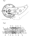
figure 5 est une vue en plan partielle d'une troisième forme d'exécution du mouvement d'horlogerie. - La
figure 6 est une coupe suivant la ligne III-III de lafigure 5 . - La
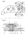
figure 7 est une vue en plan à plus grande échelle de dessous, la platine étant retirée du mouvement illustré auxfigures 5 et 6 . - La
figure 8 est une coupe suivant la ligne IV-IV de lafigure 7 . - La
figure 9 est une vue en plan partielle d'une quatrième forme d'exécution du mouvement d'horlogerie. - La
figure 10 est une coupe suivant la ligne V-V de lafigure 9 . - La
figure 11 est une vue en plan de dessus de l'ensemble monobloc de la quatrième forme d'exécution du mouvement. - La
figure 12 est une vue en plan de dessous de l'ensemble monobloc de la quatrième forme d'exécution du mouvement. - La
figure 13 est une vue en perspective de l'ensemble monobloc illustré auxfigures 11 et 12 vue de dessus. - La
figure 14 est une vue en perspective de l'ensemble monobloc illustré auxfigures 11 et 12 vue de dessous.
- The
figure 1 is a partial plan view of a first embodiment of the watch movement. - The
figure 2 is a section along line II of thefigure 1 . - The
figure 3 is a partial plan view of a second embodiment of the watch movement. - The
figure 4 is a section along line II-II of thefigure 3 . - The
figure 5 is a partial plan view of a third embodiment of the watch movement. - The
figure 6 is a section along line III-III of thefigure 5 . - The
figure 7 is a plan view on a larger scale from below, the plate being removed from the movement shown in FIGS.Figures 5 and 6 . - The
figure 8 is a section along line IV-IV of thefigure 7 . - The
figure 9 is a partial plan view of a fourth embodiment of the watch movement. - The
figure 10 is a section along the line VV of thefigure 9 . - The
figure 11 is a top plan view of the one-piece assembly of the fourth embodiment of the movement. - The
figure 12 is a bottom plan view of the one-piece assembly of the fourth embodiment of the movement. - The
figure 13 is a perspective view of the monoblock assembly illustrated inFigures 11 and 12 top view. - The
figure 14 is a perspective view of the monoblock assembly illustrated inFigures 11 and 12 view from below.
La première forme d'exécution illustrée aux
Dans cette première forme d'exécution, un balancier 6 est fixé de façon conventionnelle sur l'axe de balancier 5.In this first embodiment, a
L'ancre 4 comporte de façon classique une fourchette 4.1 et un dard 4.2.The
Le mouvement d'horlogerie selon la présente invention comporte encore un ensemble monobloc comprenant un spiral 7 et sa virole 7.1, un petit plateau 8 muni d'une encoche destinée à coopérer avec le dard 4.2 de l'ancre, et un grand plateau 9 comportant une cheville 10 destinée à coopérer avec la fourchette 4.1 de l'ancre 4.The watch movement according to the present invention also comprises a one-piece assembly comprising a
De préférence cet ensemble monobloc est formé à base de silicium, notamment de silicium monocristallin. Cet ensemble monobloc est réalisé par gravage de substrat du type S.O.I. (Silicon On Insulator) soit directement en une pièce soit en deux pièces si la forme est telle qu'elle ne peut pas être obtenue en une seule pièce.Preferably this one-piece assembly is formed based on silicon, especially monocrystalline silicon. This one-piece assembly is produced by etching substrate type S.O.I. (Silicon On Insulator) either directly in one piece or in two pieces if the shape is such that it can not be obtained in one piece.
Ceci est notamment le cas dans cette première forme d'exécution où le petit plateau 8 se trouve entre la virole 7.1 et le grand plateau 9. Dans ce cas les deux sous-ensembles virole - spiral et grand plateau - petit plateau obtenus par gravage de substrats du type S.O.I. sont ensuite fusionnés ensemble par des techniques de micromécanique pour former un seul ensemble monobloc.This is particularly the case in this first embodiment where the
Que l'on obtienne cet ensemble monobloc par gravage d'un substrat S.O.I. seulement ou par gravage puis fusion de deux sous-ensembles la précision que ces techniques permettent d'atteindre fait qu'il est possible de réaliser cet ensemble monobloc de manière à ce que l'angle α formé entre un premier plan passant par l'axe de l'ensemble monobloc et l'axe de symétrie de la cheville 10 et un second plan passant également par l'axe de l'ensemble monobloc et par l'extrémité de la spire extérieure du spiral respectivement du piton sur lequel elle est fixée peut être garanti avec précision.Whether this monobloc assembly is obtained by etching an SOI substrate only or by etching and then fusing two subassemblies, the precision that these techniques make it possible to achieve makes it possible to produce this monobloc assembly in such a way that that the angle α formed between a first plane passing through the axis of the one-piece assembly and the axis of symmetry of the
L'ensemble monobloc comportant le spiral 6, sa virole et les plateaux 8 et 9 comporte également un dispositif de fixation élastique de cet ensemble monobloc sur l'axe de balancier 5. Ce dispositif de fixation élastique est venu d'une pièce de fabrication avec l'ensemble monobloc ou avec l'un au moins des deux sous-ensembles le cas échéant. Ce dispositif de fixation élastique peut être intégré à la virole 7.1 du spiral par exemple comme décrit dans les brevets
L'extrémité extérieure 7.2 du spiral 7 est conformée de manière à pouvoir être accouplée rigidement à une pince 11 solidaire d'un piton 12 comme décrit par exemple dans le brevet
Le montage du balancier 6 sur l'axe de balancier 5 se fait de manière classique puis l'ensemble monobloc 7, 8, 9 est fixé sur l'axe de balancier par sa pince élastique à une position axiale de cet axe prédéterminée.The
Ensuite l'axe de balancier 5 muni du balancier 6 et de l'ensemble monobloc 7, 8, 9 est pivoté entre des paliers anti-chocs 13 montés dans la platine 1 respectivement le coq 3.Then the
L'ancre 4 est ensuite mise en place de manière à ce que sa fourchette 4.1 entoure la cheville 10 de l'ensemble monobloc 7, 8, 9 puis est montée sur un axe d'ancre 14. L'une des extrémités de l'axe d'ancre 14 est pivotée dans la platine, l'autre dans le pont d'ancre 2 qui est fixé sur la platine.The
Du fait que le spiral 7 et sa virole 7.1, le petit plateau 8 et le grand plateau 9 et sa cheville 10 constituent un ensemble monobloc le montage de ces éléments est grandement simplifié, le nombre de pièces à assembler étant réduit au minimum.Because the
De plus la hauteur hors tout de cet ensemble monobloc 7, 8, 9 peut être réduite par rapport à un assemblage de trois pièces individuelles du fait de la précision d'usinage de l'ensemble monobloc 7, 8, 9 et de la suppression du cumul des tolérances afférentes à chacun des élément 7, 8, 9 s'ils étaient fabriqués et usinés puis montés séparément.Moreover, the overall height of this one-
Cette diminution de hauteur ne s'effectue pas au détriment des distances de sécurité nécessaires au bon fonctionnement de l'échappement, notamment de l'ancre 4.This reduction in height does not take place at the expense of the safety distances necessary for the proper functioning of the escapement, in
De plus comme l'angle α entre les plans axiaux de l'ensemble 7, 8, 9 contenant l'axe de la cheville 10, respectivement l'extrémité de la spire extérieure 7.2 du spiral 7 est connu avec précision et que le piton 12 et sa pince ont une géométrie connue avec précision, il est possible de déterminer théoriquement à l'avance la position de l'axe du piton 12 pour qu'en position neutre de repos du spiral 7 l'axe de la cheville 10 soit aligné sur une droite reliant l'axe de balancier 5 à l'axe 14 de l'ancre. Ainsi l'axe du piton 12 est placé dans un perçage borgne 15 de la platine 1 dont la position et la profondeur sont prédéterminées ce qui évite l'opération de mise au repère nécessaire habituellement.Moreover, as the angle α between the axial planes of the
En fait, la position du perçage borgne dans la platine 1 détermine, compte tenu de la géométrie bien définie du piton 12 et de l'ensemble monobloc 7, 8, 9 la position de fonctionnement exacte de l'ensemble monobloc 7, 8, 9, par rapport à l'ancre 4 et assure notamment qu'en position neutre du spiral 7, l'axe de la cheville 10 soit situé dans l'alignement de l'axe 14 de l'ancre et de l'axe de balancier 5 sans qu'aucun réglage ne soit nécessaire.In fact, the position of the blind hole in the
Une autre simplification provient du fait que le piton 12 est fixé sur une partie fixe, la platine 1, du mouvement ce qui permet de supprimer tout réglage du piton et de fixer celui-ci non pas sur la raquetterie du coq mais sur n'importe quelle partie fixe du mouvement, platine 1, pont d'ancre 2 ou coq 3.Another simplification comes from the fact that the
La profondeur du perçage borgne 15 détermine la hauteur du piton 12 et donc de l'extrémité 7.2 de la spire extérieure du spiral 7 pour que celui-ci soit situé dans un plan. Cet ajustement est également automatique dans cette construction.The depth of the
Dans l'exécution illustrée le piton 12 est maintenu en place par une plaquette 16 fixée sur la platine 1 à l'aide d'une vis 17.In the illustrated embodiment the
Ainsi, grâce à la réalisation d'un ensemble monobloc comprenant le spiral 7 sa virole 7.1 et l'extrémité de sa spire extérieure 7.2, le petit plateau 8 et le grand plateau 9 et sa cheville 10 il est possible de :
- réduire l'encombrement en hauteur de l'ensemble monobloc par rapport à l'espace qui serait nécessaire dans une construction classique où le spiral, le grand et le petit plateau sont indépendants les uns des autre.
- Supprimer la mise au repère.
- Faciliter l'assemblage de l'axe de balancier au spiral et aux deux plateaux.
- Solidariser l'extrémité de la spire extérieure du spiral sur un piton solidaire d'une partie fixe du mouvement supprimant ainsi tout système de réglage.
- Réduire le nombre de pièces à assembler.
- reduce the overall height of the monobloc assembly relative to the space that would be required in a conventional construction where the spiral, the large and the small plate are independent of each other.
- Delete the setting at the marker.
- Facilitate the assembly of the balance shaft to the spiral and the two plates.
- Solidarize the end of the outer coil of the spiral on a pin secured to a fixed part of the movement thus eliminating any adjustment system.
- Reduce the number of parts to assemble.
La seconde forme d'exécution du mouvement d'horlogerie illustrée aux
Dans ces deux premières formes d'exécution décrites, le spiral 7 est noyé dans le pont d'ancre 2 en tout ou partie. La position angulaire, radiale et axiale du piton 12 est définie par la géométrie de la platine, du pont d'ancre et dudit piton; aucun réglage n'est nécessaire.In these first two described embodiments, the
Dans la troisième forme d'exécution du mouvement décrite en référence aux
Le piton 12 portant la pince 11 servant d'attache à l'extrémité extérieures 7.2 du spiral 7 est logé dans un perçage du pont d'ancre 20 définissant automatiquement ses positions radiale et angulaire. Une vis latérale 21 bloque le piton 12 dans sa position axiale de service ajustée au montage par un horloger.The
Comme on le voit aux
Dans les trois formes d'exécution décrites ci-dessus, l'ensemble monobloc 7, 8, 9 comporte toujours dans sa partie supérieure le spiral 7 et sa virole 7.1 comportant une première pince élastique de fixation 22, dans sa partie médiane, le petit plateau 8 et son encoche, et dans sa partie inférieure le grand plateau 9 et sa cheville 10. Une seconde pince élastique de fixation 23 est située au niveau des deux plateaux 8 et 9 et est venue d'une pièce de fabrication avec l'un ou les deux desdits plateaux 8, 9.In the three embodiments described above, the one-
Il est évident que dans des variantes l'ordre dans lequel se succèdent les différents organes 7, 8, 9 de cet ensemble monobloc peut être différent. Par exemple le grand plateau 9 pourrait être situé entre le petit plateau 8 et le spiral 7. De même le spiral 7 pourrait former la partie inférieure de l'ensemble monobloc plutôt que sa partie supérieure.It is obvious that, in variants, the order in which the
Lorsque le grand plateau 9 occupe la partie médiane de l'ensemble monobloc 7, 8, 9 il est possible de réaliser celui-ci par gravage d'un seul substrat S.O.I ce qui en facilite la fabrication.When the
Une quatrième forme d'exécution du mouvement d'horlogerie est illustrée aux
Dans cette forme d'exécution, le mouvement comporte également une platine 1, un pont d'ancre 2 et un coq 3. Un axe de balancier 5 est pivoté entre le coq 3 et la platine tandis qu'une ancre 4 est pivotée par son axe d'ancre 14 entre la platine 1 et le pont d'ancre 2.In this embodiment, the movement also comprises a
Dans cette forme d'exécution, l'arbre de balancier 5 porte toujours les mêmes éléments, à savoir le balancier 6, le spiral 7, le petit plateau 8 et le grand plateau 9. La différence par rapport aux formes d'exécutions décrites précédemment est que le balancier 6 est intégré dans l'ensemble monobloc et fait partie intégrante de celui-ci. Dans cette forme d'exécution l'ensemble monobloc 6, 7, 8, 9 inclut le spiral 7 et sa virole 7.1, le balancier 6, le petit plateau 8 et le grand plateau 9 et sa cheville 10. Dans l'exemple illustré, le balancier 6 est situé entre le spiral 7 et le petit plateau 8. Le spiral 7 constitue donc la partie supérieure de l'ensemble monobloc 6, 7, 8, 9. L'extrémité extérieure 7.2 du spiral 7 est fixée dans une pince 11 solidaire d'un piton 12 qui lui-même est fixé dans le coq 3 dans une position prédéterminée non réglable.In this embodiment, the
La virole 7.1 du spiral 7 comporte une première pince élastique 22 tandis qu'une seconde pince élastique 23 fait partie des grand et petit plateau 8, 9 ou au moins d'un de ces plateaux.The ferrule 7.1 of the
Cette forme d'exécution permet de réduire encore le nombre de pièces et de faciliter le montage du mouvement en éliminant la plupart, voir tous les réglages, cette forme d'exécution est donc particulièrement intéressante.This form of execution can further reduce the number of parts and facilitate the assembly of the movement by eliminating most, see all settings, this form of execution is particularly interesting.
Dans toutes les formes d'exécution du mouvement décrit grâce à la précision de fabrication de l'ensemble monobloc, le piton fixant l'extrémité du spiral peut être fixé sur une partie fixe du mouvement, platine, pont d'ancre ou coq, dans une position prédéterminée à l'avance qui assurera que lorsque l'élément monobloc sera dans la position axiale neutre du spiral, la cheville soit alignée sur la droite reliant les axes de pivotement de la fourchette et du balancier.In all the embodiments of the movement described by virtue of the precision of manufacture of the one-piece assembly, the stud fixing the end of the hairspring can be fixed on a fixed part of the movement, platinum, anchor bridge or cock, in a predetermined position in advance which will ensure that when the monobloc element will be in the neutral axial position of the spiral, the peg is aligned on the straight line connecting the pivot axes of the fork and the balance.
L'assemblage de cette partie délicate du mouvement qu'est l'organe réglant et l'organe distributeur devient facile, rapide et ne nécessite plus de réglage.The assembly of this delicate part of the movement that is the regulating organ and the dispenser member becomes easy, fast and no longer requires adjustment.
Claims (15)
Priority Applications (2)
| Application Number | Priority Date | Filing Date | Title |
|---|---|---|---|
| EP20110007420 EP2570868B1 (en) | 2011-09-13 | 2011-09-13 | Part for a clockwork, clockwork and timepiece |
| HK13103674.2A HK1176693A1 (en) | 2011-09-13 | 2013-03-25 | Part for a clockwork, clockwork and timepiece |
Applications Claiming Priority (1)
| Application Number | Priority Date | Filing Date | Title |
|---|---|---|---|
| EP20110007420 EP2570868B1 (en) | 2011-09-13 | 2011-09-13 | Part for a clockwork, clockwork and timepiece |
Publications (2)
| Publication Number | Publication Date |
|---|---|
| EP2570868A1 true EP2570868A1 (en) | 2013-03-20 |
| EP2570868B1 EP2570868B1 (en) | 2014-09-03 |
Family
ID=44650866
Family Applications (1)
| Application Number | Title | Priority Date | Filing Date |
|---|---|---|---|
| EP20110007420 Active EP2570868B1 (en) | 2011-09-13 | 2011-09-13 | Part for a clockwork, clockwork and timepiece |
Country Status (2)
| Country | Link |
|---|---|
| EP (1) | EP2570868B1 (en) |
| HK (1) | HK1176693A1 (en) |
Cited By (5)
| Publication number | Priority date | Publication date | Assignee | Title |
|---|---|---|---|---|
| EP2579105A3 (en) * | 2011-10-07 | 2013-08-07 | CSEM Centre Suisse d'Electronique et de Microtechnique SA - Recherche et Développement | Method for manufacturing a timepiece |
| EP3032354A1 (en) | 2014-11-27 | 2016-06-15 | Rolex Sa | System for attaching a hairspring |
| EP3182215A1 (en) * | 2015-12-14 | 2017-06-21 | Novasort SA | Oscillating system for timepiece |
| EP4099101A1 (en) | 2021-06-03 | 2022-12-07 | Rolex Sa | Device for assembling a timepiece oscillator |
| WO2023066614A1 (en) | 2021-10-20 | 2023-04-27 | Rolex Sa | Method for determining a reference value and method for setting a reference value |
Citations (6)
| Publication number | Priority date | Publication date | Assignee | Title |
|---|---|---|---|---|
| FR583885A (en) * | 1924-07-21 | 1925-01-23 | Tavannes Watch Co Sa | Anchor assortment |
| FR2262823A1 (en) * | 1974-03-02 | 1975-09-26 | Diehl | |
| EP1431844A1 (en) * | 2002-12-19 | 2004-06-23 | SFT Services SA | Assembly for the regulating organ of a watch movement |
| CH698876B1 (en) | 2006-05-17 | 2009-11-30 | Patek Philippe Sa | spiral-ring set for clockwork. |
| CH700805B1 (en) | 2005-10-25 | 2010-10-29 | Patek Philippe Sa Geneve | Device controller for a timepiece and watch movement comprising such a device. |
| EP2322996A1 (en) | 2009-11-13 | 2011-05-18 | Nivarox-FAR S.A. | Balance wheel - hairspring resonator for clock piece |
-
2011
- 2011-09-13 EP EP20110007420 patent/EP2570868B1/en active Active
-
2013
- 2013-03-25 HK HK13103674.2A patent/HK1176693A1/en unknown
Patent Citations (6)
| Publication number | Priority date | Publication date | Assignee | Title |
|---|---|---|---|---|
| FR583885A (en) * | 1924-07-21 | 1925-01-23 | Tavannes Watch Co Sa | Anchor assortment |
| FR2262823A1 (en) * | 1974-03-02 | 1975-09-26 | Diehl | |
| EP1431844A1 (en) * | 2002-12-19 | 2004-06-23 | SFT Services SA | Assembly for the regulating organ of a watch movement |
| CH700805B1 (en) | 2005-10-25 | 2010-10-29 | Patek Philippe Sa Geneve | Device controller for a timepiece and watch movement comprising such a device. |
| CH698876B1 (en) | 2006-05-17 | 2009-11-30 | Patek Philippe Sa | spiral-ring set for clockwork. |
| EP2322996A1 (en) | 2009-11-13 | 2011-05-18 | Nivarox-FAR S.A. | Balance wheel - hairspring resonator for clock piece |
Cited By (9)
| Publication number | Priority date | Publication date | Assignee | Title |
|---|---|---|---|---|
| EP2579105A3 (en) * | 2011-10-07 | 2013-08-07 | CSEM Centre Suisse d'Electronique et de Microtechnique SA - Recherche et Développement | Method for manufacturing a timepiece |
| EP3032354A1 (en) | 2014-11-27 | 2016-06-15 | Rolex Sa | System for attaching a hairspring |
| US9811054B2 (en) | 2014-11-27 | 2017-11-07 | Rolex Sa | System for securing a balance spring |
| EP3182215A1 (en) * | 2015-12-14 | 2017-06-21 | Novasort SA | Oscillating system for timepiece |
| WO2017102845A1 (en) * | 2015-12-14 | 2017-06-22 | Novasort Sa | Oscillating system for a watch |
| EP3499318A1 (en) * | 2015-12-14 | 2019-06-19 | Novasort SA | Oscillator system for a watch |
| US11415941B2 (en) | 2015-12-14 | 2022-08-16 | Wcp (Watch Connaisseur Project) Sa | Oscillating system for a watch |
| EP4099101A1 (en) | 2021-06-03 | 2022-12-07 | Rolex Sa | Device for assembling a timepiece oscillator |
| WO2023066614A1 (en) | 2021-10-20 | 2023-04-27 | Rolex Sa | Method for determining a reference value and method for setting a reference value |
Also Published As
| Publication number | Publication date |
|---|---|
| HK1176693A1 (en) | 2013-08-02 |
| EP2570868B1 (en) | 2014-09-03 |
Similar Documents
| Publication | Publication Date | Title |
|---|---|---|
| EP2273323B1 (en) | Mechanical oscillator | |
| EP1991916B1 (en) | Micromechanical piece with form opening for assembly on a spindle | |
| EP2196868B1 (en) | Hairspring with curve elevation made from a silicon-based material | |
| EP2570868B1 (en) | Part for a clockwork, clockwork and timepiece | |
| EP2437126B1 (en) | Balance wheel-hairspring regulator | |
| EP2735921B1 (en) | Clock escapement holder | |
| EP3356690A1 (en) | Flexible-pivot mechanical component and timekeeping device including same | |
| EP3206089A1 (en) | Timepiece resonator mechanism | |
| EP2998800A2 (en) | Timepiece component with flexible pivot | |
| EP2799937B1 (en) | Shock-proof bearing for an horological balance | |
| CH701783A1 (en) | Spiral spring. | |
| EP3502784A1 (en) | Timepiece resonator with flexible guide | |
| EP3011396B1 (en) | Secure-mount antishock system | |
| EP3032354A1 (en) | System for attaching a hairspring | |
| EP3032353B1 (en) | Detachable stud support | |
| EP2506093B1 (en) | Balance for clockwork | |
| CH705484A2 (en) | Clockwork for use in clock element, has spiral unit that is arranged interdependent of ring, large plate carrying pin, small plate provided with notch, where spiral unit, ring, large plate, pin and small plate form single-piece unit | |
| FR3065542B1 (en) | METHOD FOR MANUFACTURING A MECHANISM | |
| EP3391154B1 (en) | Oscillating system for timepiece | |
| EP3839651A1 (en) | Mechanical timepiece oscillator with flexible guide | |
| EP3637196A1 (en) | Mechanical oscillator | |
| CH716400B1 (en) | Clockwork movement with a mobile rotating peak for setting the balance-spring. | |
| EP3432082A1 (en) | Regulating mechanism | |
| EP3470932B1 (en) | Oscillator for a timepiece movement | |
| EP4099101A1 (en) | Device for assembling a timepiece oscillator |
Legal Events
| Date | Code | Title | Description |
|---|---|---|---|
| PUAI | Public reference made under article 153(3) epc to a published international application that has entered the european phase |
Free format text: ORIGINAL CODE: 0009012 |
|
| AK | Designated contracting states |
Kind code of ref document: A1 Designated state(s): AL AT BE BG CH CY CZ DE DK EE ES FI FR GB GR HR HU IE IS IT LI LT LU LV MC MK MT NL NO PL PT RO RS SE SI SK SM TR |
|
| AX | Request for extension of the european patent |
Extension state: BA ME |
|
| REG | Reference to a national code |
Ref country code: HK Ref legal event code: DE Ref document number: 1176693 Country of ref document: HK |
|
| 17P | Request for examination filed |
Effective date: 20130824 |
|
| RBV | Designated contracting states (corrected) |
Designated state(s): AL AT BE BG CH CY CZ DE DK EE ES FI FR GB GR HR HU IE IS IT LI LT LU LV MC MK MT NL NO PL PT RO RS SE SI SK SM TR |
|
| RIC1 | Information provided on ipc code assigned before grant |
Ipc: G04B 17/06 20060101ALI20140307BHEP Ipc: G04B 15/08 20060101AFI20140307BHEP Ipc: G04B 17/32 20060101ALI20140307BHEP |
|
| GRAP | Despatch of communication of intention to grant a patent |
Free format text: ORIGINAL CODE: EPIDOSNIGR1 |
|
| INTG | Intention to grant announced |
Effective date: 20140428 |
|
| GRAS | Grant fee paid |
Free format text: ORIGINAL CODE: EPIDOSNIGR3 |
|
| GRAA | (expected) grant |
Free format text: ORIGINAL CODE: 0009210 |
|
| AK | Designated contracting states |
Kind code of ref document: B1 Designated state(s): AL AT BE BG CH CY CZ DE DK EE ES FI FR GB GR HR HU IE IS IT LI LT LU LV MC MK MT NL NO PL PT RO RS SE SI SK SM TR |
|
| REG | Reference to a national code |
Ref country code: GB Ref legal event code: FG4D Free format text: NOT ENGLISH |
|
| REG | Reference to a national code |
Ref country code: AT Ref legal event code: REF Ref document number: 685900 Country of ref document: AT Kind code of ref document: T Effective date: 20140915 Ref country code: CH Ref legal event code: EP |
|
| REG | Reference to a national code |
Ref country code: IE Ref legal event code: FG4D Free format text: LANGUAGE OF EP DOCUMENT: FRENCH |
|
| REG | Reference to a national code |
Ref country code: CH Ref legal event code: NV Representative=s name: MICHELI AND CIE SA, CH |
|
| REG | Reference to a national code |
Ref country code: DE Ref legal event code: R096 Ref document number: 602011009550 Country of ref document: DE Effective date: 20141016 |
|
| REG | Reference to a national code |
Ref country code: AT Ref legal event code: MK05 Ref document number: 685900 Country of ref document: AT Kind code of ref document: T Effective date: 20140903 |
|
| REG | Reference to a national code |
Ref country code: HK Ref legal event code: GR Ref document number: 1176693 Country of ref document: HK |
|
| PG25 | Lapsed in a contracting state [announced via postgrant information from national office to epo] |
Ref country code: FI Free format text: LAPSE BECAUSE OF FAILURE TO SUBMIT A TRANSLATION OF THE DESCRIPTION OR TO PAY THE FEE WITHIN THE PRESCRIBED TIME-LIMIT Effective date: 20140903 Ref country code: ES Free format text: LAPSE BECAUSE OF FAILURE TO SUBMIT A TRANSLATION OF THE DESCRIPTION OR TO PAY THE FEE WITHIN THE PRESCRIBED TIME-LIMIT Effective date: 20140903 Ref country code: SE Free format text: LAPSE BECAUSE OF FAILURE TO SUBMIT A TRANSLATION OF THE DESCRIPTION OR TO PAY THE FEE WITHIN THE PRESCRIBED TIME-LIMIT Effective date: 20140903 Ref country code: LT Free format text: LAPSE BECAUSE OF FAILURE TO SUBMIT A TRANSLATION OF THE DESCRIPTION OR TO PAY THE FEE WITHIN THE PRESCRIBED TIME-LIMIT Effective date: 20140903 Ref country code: GR Free format text: LAPSE BECAUSE OF FAILURE TO SUBMIT A TRANSLATION OF THE DESCRIPTION OR TO PAY THE FEE WITHIN THE PRESCRIBED TIME-LIMIT Effective date: 20141204 Ref country code: NO Free format text: LAPSE BECAUSE OF FAILURE TO SUBMIT A TRANSLATION OF THE DESCRIPTION OR TO PAY THE FEE WITHIN THE PRESCRIBED TIME-LIMIT Effective date: 20141203 |
|
| REG | Reference to a national code |
Ref country code: NL Ref legal event code: VDEP Effective date: 20140903 |
|
| REG | Reference to a national code |
Ref country code: LT Ref legal event code: MG4D |
|
| PG25 | Lapsed in a contracting state [announced via postgrant information from national office to epo] |
Ref country code: AT Free format text: LAPSE BECAUSE OF FAILURE TO SUBMIT A TRANSLATION OF THE DESCRIPTION OR TO PAY THE FEE WITHIN THE PRESCRIBED TIME-LIMIT Effective date: 20140903 Ref country code: HR Free format text: LAPSE BECAUSE OF FAILURE TO SUBMIT A TRANSLATION OF THE DESCRIPTION OR TO PAY THE FEE WITHIN THE PRESCRIBED TIME-LIMIT Effective date: 20140903 Ref country code: RS Free format text: LAPSE BECAUSE OF FAILURE TO SUBMIT A TRANSLATION OF THE DESCRIPTION OR TO PAY THE FEE WITHIN THE PRESCRIBED TIME-LIMIT Effective date: 20140903 Ref country code: CY Free format text: LAPSE BECAUSE OF FAILURE TO SUBMIT A TRANSLATION OF THE DESCRIPTION OR TO PAY THE FEE WITHIN THE PRESCRIBED TIME-LIMIT Effective date: 20140903 Ref country code: LV Free format text: LAPSE BECAUSE OF FAILURE TO SUBMIT A TRANSLATION OF THE DESCRIPTION OR TO PAY THE FEE WITHIN THE PRESCRIBED TIME-LIMIT Effective date: 20140903 |
|
| PG25 | Lapsed in a contracting state [announced via postgrant information from national office to epo] |
Ref country code: NL Free format text: LAPSE BECAUSE OF FAILURE TO SUBMIT A TRANSLATION OF THE DESCRIPTION OR TO PAY THE FEE WITHIN THE PRESCRIBED TIME-LIMIT Effective date: 20140903 |
|
| PG25 | Lapsed in a contracting state [announced via postgrant information from national office to epo] |
Ref country code: PT Free format text: LAPSE BECAUSE OF FAILURE TO SUBMIT A TRANSLATION OF THE DESCRIPTION OR TO PAY THE FEE WITHIN THE PRESCRIBED TIME-LIMIT Effective date: 20150105 Ref country code: EE Free format text: LAPSE BECAUSE OF FAILURE TO SUBMIT A TRANSLATION OF THE DESCRIPTION OR TO PAY THE FEE WITHIN THE PRESCRIBED TIME-LIMIT Effective date: 20140903 Ref country code: CZ Free format text: LAPSE BECAUSE OF FAILURE TO SUBMIT A TRANSLATION OF THE DESCRIPTION OR TO PAY THE FEE WITHIN THE PRESCRIBED TIME-LIMIT Effective date: 20140903 Ref country code: IS Free format text: LAPSE BECAUSE OF FAILURE TO SUBMIT A TRANSLATION OF THE DESCRIPTION OR TO PAY THE FEE WITHIN THE PRESCRIBED TIME-LIMIT Effective date: 20150103 Ref country code: SK Free format text: LAPSE BECAUSE OF FAILURE TO SUBMIT A TRANSLATION OF THE DESCRIPTION OR TO PAY THE FEE WITHIN THE PRESCRIBED TIME-LIMIT Effective date: 20140903 Ref country code: RO Free format text: LAPSE BECAUSE OF FAILURE TO SUBMIT A TRANSLATION OF THE DESCRIPTION OR TO PAY THE FEE WITHIN THE PRESCRIBED TIME-LIMIT Effective date: 20140903 |
|
| PG25 | Lapsed in a contracting state [announced via postgrant information from national office to epo] |
Ref country code: PL Free format text: LAPSE BECAUSE OF FAILURE TO SUBMIT A TRANSLATION OF THE DESCRIPTION OR TO PAY THE FEE WITHIN THE PRESCRIBED TIME-LIMIT Effective date: 20140903 |
|
| REG | Reference to a national code |
Ref country code: DE Ref legal event code: R097 Ref document number: 602011009550 Country of ref document: DE |
|
| REG | Reference to a national code |
Ref country code: IE Ref legal event code: MM4A |
|
| PG25 | Lapsed in a contracting state [announced via postgrant information from national office to epo] |
Ref country code: MC Free format text: LAPSE BECAUSE OF FAILURE TO SUBMIT A TRANSLATION OF THE DESCRIPTION OR TO PAY THE FEE WITHIN THE PRESCRIBED TIME-LIMIT Effective date: 20140903 Ref country code: BE Free format text: LAPSE BECAUSE OF NON-PAYMENT OF DUE FEES Effective date: 20140930 |
|
| PLBE | No opposition filed within time limit |
Free format text: ORIGINAL CODE: 0009261 |
|
| STAA | Information on the status of an ep patent application or granted ep patent |
Free format text: STATUS: NO OPPOSITION FILED WITHIN TIME LIMIT |
|
| PG25 | Lapsed in a contracting state [announced via postgrant information from national office to epo] |
Ref country code: DK Free format text: LAPSE BECAUSE OF FAILURE TO SUBMIT A TRANSLATION OF THE DESCRIPTION OR TO PAY THE FEE WITHIN THE PRESCRIBED TIME-LIMIT Effective date: 20140903 |
|
| 26N | No opposition filed |
Effective date: 20150604 |
|
| PG25 | Lapsed in a contracting state [announced via postgrant information from national office to epo] |
Ref country code: IT Free format text: LAPSE BECAUSE OF FAILURE TO SUBMIT A TRANSLATION OF THE DESCRIPTION OR TO PAY THE FEE WITHIN THE PRESCRIBED TIME-LIMIT Effective date: 20140903 Ref country code: IE Free format text: LAPSE BECAUSE OF NON-PAYMENT OF DUE FEES Effective date: 20140913 |
|
| PG25 | Lapsed in a contracting state [announced via postgrant information from national office to epo] |
Ref country code: SI Free format text: LAPSE BECAUSE OF FAILURE TO SUBMIT A TRANSLATION OF THE DESCRIPTION OR TO PAY THE FEE WITHIN THE PRESCRIBED TIME-LIMIT Effective date: 20140903 |
|
| PG25 | Lapsed in a contracting state [announced via postgrant information from national office to epo] |
Ref country code: SM Free format text: LAPSE BECAUSE OF FAILURE TO SUBMIT A TRANSLATION OF THE DESCRIPTION OR TO PAY THE FEE WITHIN THE PRESCRIBED TIME-LIMIT Effective date: 20140903 |
|
| PG25 | Lapsed in a contracting state [announced via postgrant information from national office to epo] |
Ref country code: MT Free format text: LAPSE BECAUSE OF FAILURE TO SUBMIT A TRANSLATION OF THE DESCRIPTION OR TO PAY THE FEE WITHIN THE PRESCRIBED TIME-LIMIT Effective date: 20140903 Ref country code: BG Free format text: LAPSE BECAUSE OF FAILURE TO SUBMIT A TRANSLATION OF THE DESCRIPTION OR TO PAY THE FEE WITHIN THE PRESCRIBED TIME-LIMIT Effective date: 20140903 |
|
| PG25 | Lapsed in a contracting state [announced via postgrant information from national office to epo] |
Ref country code: HU Free format text: LAPSE BECAUSE OF FAILURE TO SUBMIT A TRANSLATION OF THE DESCRIPTION OR TO PAY THE FEE WITHIN THE PRESCRIBED TIME-LIMIT; INVALID AB INITIO Effective date: 20110913 Ref country code: LU Free format text: LAPSE BECAUSE OF NON-PAYMENT OF DUE FEES Effective date: 20140913 Ref country code: TR Free format text: LAPSE BECAUSE OF FAILURE TO SUBMIT A TRANSLATION OF THE DESCRIPTION OR TO PAY THE FEE WITHIN THE PRESCRIBED TIME-LIMIT Effective date: 20140903 |
|
| REG | Reference to a national code |
Ref country code: FR Ref legal event code: PLFP Year of fee payment: 6 |
|
| REG | Reference to a national code |
Ref country code: FR Ref legal event code: PLFP Year of fee payment: 7 |
|
| PG25 | Lapsed in a contracting state [announced via postgrant information from national office to epo] |
Ref country code: MK Free format text: LAPSE BECAUSE OF FAILURE TO SUBMIT A TRANSLATION OF THE DESCRIPTION OR TO PAY THE FEE WITHIN THE PRESCRIBED TIME-LIMIT Effective date: 20140903 |
|
| REG | Reference to a national code |
Ref country code: FR Ref legal event code: PLFP Year of fee payment: 8 |
|
| PG25 | Lapsed in a contracting state [announced via postgrant information from national office to epo] |
Ref country code: AL Free format text: LAPSE BECAUSE OF FAILURE TO SUBMIT A TRANSLATION OF THE DESCRIPTION OR TO PAY THE FEE WITHIN THE PRESCRIBED TIME-LIMIT Effective date: 20140903 |
|
| P01 | Opt-out of the competence of the unified patent court (upc) registered |
Effective date: 20230521 |
|
| PGFP | Annual fee paid to national office [announced via postgrant information from national office to epo] |
Ref country code: GB Payment date: 20230720 Year of fee payment: 13 |
|
| PGFP | Annual fee paid to national office [announced via postgrant information from national office to epo] |
Ref country code: FR Payment date: 20230721 Year of fee payment: 13 Ref country code: DE Payment date: 20230718 Year of fee payment: 13 |
|
| PGFP | Annual fee paid to national office [announced via postgrant information from national office to epo] |
Ref country code: CH Payment date: 20231001 Year of fee payment: 13 |