EP2570663A2 - Antriebsstrang und Verfahren zur Lagerschmierung in einer Windturbine - Google Patents
Antriebsstrang und Verfahren zur Lagerschmierung in einer Windturbine Download PDFInfo
- Publication number
- EP2570663A2 EP2570663A2 EP12183115A EP12183115A EP2570663A2 EP 2570663 A2 EP2570663 A2 EP 2570663A2 EP 12183115 A EP12183115 A EP 12183115A EP 12183115 A EP12183115 A EP 12183115A EP 2570663 A2 EP2570663 A2 EP 2570663A2
- Authority
- EP
- European Patent Office
- Prior art keywords
- drivetrain
- bearing
- wind turbine
- lubrication
- lubrication fluid
- Prior art date
- Legal status (The legal status is an assumption and is not a legal conclusion. Google has not performed a legal analysis and makes no representation as to the accuracy of the status listed.)
- Withdrawn
Links
Images


Classifications
-
- F—MECHANICAL ENGINEERING; LIGHTING; HEATING; WEAPONS; BLASTING
- F16—ENGINEERING ELEMENTS AND UNITS; GENERAL MEASURES FOR PRODUCING AND MAINTAINING EFFECTIVE FUNCTIONING OF MACHINES OR INSTALLATIONS; THERMAL INSULATION IN GENERAL
- F16C—SHAFTS; FLEXIBLE SHAFTS; ELEMENTS OR CRANKSHAFT MECHANISMS; ROTARY BODIES OTHER THAN GEARING ELEMENTS; BEARINGS
- F16C33/00—Parts of bearings; Special methods for making bearings or parts thereof
- F16C33/30—Parts of ball or roller bearings
- F16C33/66—Special parts or details in view of lubrication
- F16C33/6637—Special parts or details in view of lubrication with liquid lubricant
- F16C33/6685—Details of collecting or draining, e.g. returning the liquid to a sump
-
- F—MECHANICAL ENGINEERING; LIGHTING; HEATING; WEAPONS; BLASTING
- F03—MACHINES OR ENGINES FOR LIQUIDS; WIND, SPRING, OR WEIGHT MOTORS; PRODUCING MECHANICAL POWER OR A REACTIVE PROPULSIVE THRUST, NOT OTHERWISE PROVIDED FOR
- F03D—WIND MOTORS
- F03D15/00—Transmission of mechanical power
-
- F—MECHANICAL ENGINEERING; LIGHTING; HEATING; WEAPONS; BLASTING
- F03—MACHINES OR ENGINES FOR LIQUIDS; WIND, SPRING, OR WEIGHT MOTORS; PRODUCING MECHANICAL POWER OR A REACTIVE PROPULSIVE THRUST, NOT OTHERWISE PROVIDED FOR
- F03D—WIND MOTORS
- F03D15/00—Transmission of mechanical power
- F03D15/10—Transmission of mechanical power using gearing not limited to rotary motion, e.g. with oscillating or reciprocating members
-
- F—MECHANICAL ENGINEERING; LIGHTING; HEATING; WEAPONS; BLASTING
- F03—MACHINES OR ENGINES FOR LIQUIDS; WIND, SPRING, OR WEIGHT MOTORS; PRODUCING MECHANICAL POWER OR A REACTIVE PROPULSIVE THRUST, NOT OTHERWISE PROVIDED FOR
- F03D—WIND MOTORS
- F03D80/00—Details, components or accessories not provided for in groups F03D1/00 - F03D17/00
- F03D80/70—Bearing or lubricating arrangements
-
- F—MECHANICAL ENGINEERING; LIGHTING; HEATING; WEAPONS; BLASTING
- F16—ENGINEERING ELEMENTS AND UNITS; GENERAL MEASURES FOR PRODUCING AND MAINTAINING EFFECTIVE FUNCTIONING OF MACHINES OR INSTALLATIONS; THERMAL INSULATION IN GENERAL
- F16C—SHAFTS; FLEXIBLE SHAFTS; ELEMENTS OR CRANKSHAFT MECHANISMS; ROTARY BODIES OTHER THAN GEARING ELEMENTS; BEARINGS
- F16C33/00—Parts of bearings; Special methods for making bearings or parts thereof
- F16C33/30—Parts of ball or roller bearings
- F16C33/66—Special parts or details in view of lubrication
- F16C33/6637—Special parts or details in view of lubrication with liquid lubricant
- F16C33/6659—Details of supply of the liquid to the bearing, e.g. passages or nozzles
-
- F—MECHANICAL ENGINEERING; LIGHTING; HEATING; WEAPONS; BLASTING
- F16—ENGINEERING ELEMENTS AND UNITS; GENERAL MEASURES FOR PRODUCING AND MAINTAINING EFFECTIVE FUNCTIONING OF MACHINES OR INSTALLATIONS; THERMAL INSULATION IN GENERAL
- F16N—LUBRICATING
- F16N7/00—Arrangements for supplying oil or unspecified lubricant from a stationary reservoir or the equivalent in or on the machine or member to be lubricated
- F16N7/38—Arrangements for supplying oil or unspecified lubricant from a stationary reservoir or the equivalent in or on the machine or member to be lubricated with a separate pump; Central lubrication systems
- F16N7/40—Arrangements for supplying oil or unspecified lubricant from a stationary reservoir or the equivalent in or on the machine or member to be lubricated with a separate pump; Central lubrication systems in a closed circulation system
-
- F—MECHANICAL ENGINEERING; LIGHTING; HEATING; WEAPONS; BLASTING
- F05—INDEXING SCHEMES RELATING TO ENGINES OR PUMPS IN VARIOUS SUBCLASSES OF CLASSES F01-F04
- F05B—INDEXING SCHEME RELATING TO WIND, SPRING, WEIGHT, INERTIA OR LIKE MOTORS, TO MACHINES OR ENGINES FOR LIQUIDS COVERED BY SUBCLASSES F03B, F03D AND F03G
- F05B2260/00—Function
- F05B2260/60—Fluid transfer
- F05B2260/602—Drainage
- F05B2260/603—Drainage of leakage having past a seal
-
- F—MECHANICAL ENGINEERING; LIGHTING; HEATING; WEAPONS; BLASTING
- F05—INDEXING SCHEMES RELATING TO ENGINES OR PUMPS IN VARIOUS SUBCLASSES OF CLASSES F01-F04
- F05B—INDEXING SCHEME RELATING TO WIND, SPRING, WEIGHT, INERTIA OR LIKE MOTORS, TO MACHINES OR ENGINES FOR LIQUIDS COVERED BY SUBCLASSES F03B, F03D AND F03G
- F05B2260/00—Function
- F05B2260/98—Lubrication
-
- F—MECHANICAL ENGINEERING; LIGHTING; HEATING; WEAPONS; BLASTING
- F16—ENGINEERING ELEMENTS AND UNITS; GENERAL MEASURES FOR PRODUCING AND MAINTAINING EFFECTIVE FUNCTIONING OF MACHINES OR INSTALLATIONS; THERMAL INSULATION IN GENERAL
- F16C—SHAFTS; FLEXIBLE SHAFTS; ELEMENTS OR CRANKSHAFT MECHANISMS; ROTARY BODIES OTHER THAN GEARING ELEMENTS; BEARINGS
- F16C19/00—Bearings with rolling contact, for exclusively rotary movement
- F16C19/22—Bearings with rolling contact, for exclusively rotary movement with bearing rollers essentially of the same size in one or more circular rows, e.g. needle bearings
- F16C19/34—Bearings with rolling contact, for exclusively rotary movement with bearing rollers essentially of the same size in one or more circular rows, e.g. needle bearings for both radial and axial load
- F16C19/38—Bearings with rolling contact, for exclusively rotary movement with bearing rollers essentially of the same size in one or more circular rows, e.g. needle bearings for both radial and axial load with two or more rows of rollers
- F16C19/383—Bearings with rolling contact, for exclusively rotary movement with bearing rollers essentially of the same size in one or more circular rows, e.g. needle bearings for both radial and axial load with two or more rows of rollers with tapered rollers, i.e. rollers having essentially the shape of a truncated cone
- F16C19/385—Bearings with rolling contact, for exclusively rotary movement with bearing rollers essentially of the same size in one or more circular rows, e.g. needle bearings for both radial and axial load with two or more rows of rollers with tapered rollers, i.e. rollers having essentially the shape of a truncated cone with two rows, i.e. double-row tapered roller bearings
- F16C19/386—Bearings with rolling contact, for exclusively rotary movement with bearing rollers essentially of the same size in one or more circular rows, e.g. needle bearings for both radial and axial load with two or more rows of rollers with tapered rollers, i.e. rollers having essentially the shape of a truncated cone with two rows, i.e. double-row tapered roller bearings in O-arrangement
-
- F—MECHANICAL ENGINEERING; LIGHTING; HEATING; WEAPONS; BLASTING
- F16—ENGINEERING ELEMENTS AND UNITS; GENERAL MEASURES FOR PRODUCING AND MAINTAINING EFFECTIVE FUNCTIONING OF MACHINES OR INSTALLATIONS; THERMAL INSULATION IN GENERAL
- F16C—SHAFTS; FLEXIBLE SHAFTS; ELEMENTS OR CRANKSHAFT MECHANISMS; ROTARY BODIES OTHER THAN GEARING ELEMENTS; BEARINGS
- F16C2360/00—Engines or pumps
- F16C2360/31—Wind motors
-
- F—MECHANICAL ENGINEERING; LIGHTING; HEATING; WEAPONS; BLASTING
- F16—ENGINEERING ELEMENTS AND UNITS; GENERAL MEASURES FOR PRODUCING AND MAINTAINING EFFECTIVE FUNCTIONING OF MACHINES OR INSTALLATIONS; THERMAL INSULATION IN GENERAL
- F16N—LUBRICATING
- F16N2210/00—Applications
- F16N2210/02—Turbines
- F16N2210/025—Wind Turbines
-
- Y—GENERAL TAGGING OF NEW TECHNOLOGICAL DEVELOPMENTS; GENERAL TAGGING OF CROSS-SECTIONAL TECHNOLOGIES SPANNING OVER SEVERAL SECTIONS OF THE IPC; TECHNICAL SUBJECTS COVERED BY FORMER USPC CROSS-REFERENCE ART COLLECTIONS [XRACs] AND DIGESTS
- Y02—TECHNOLOGIES OR APPLICATIONS FOR MITIGATION OR ADAPTATION AGAINST CLIMATE CHANGE
- Y02E—REDUCTION OF GREENHOUSE GAS [GHG] EMISSIONS, RELATED TO ENERGY GENERATION, TRANSMISSION OR DISTRIBUTION
- Y02E10/00—Energy generation through renewable energy sources
- Y02E10/70—Wind energy
- Y02E10/72—Wind turbines with rotation axis in wind direction
Definitions
- the present disclosure relates in general to wind turbines, and more particularly to drivetrains and methods for lubricating bearings in drivetrains in wind turbines.
- a modem wind turbine typically includes a tower, generator, gearbox, nacelle, and one or more rotor blades.
- the rotor blades capture kinetic energy of wind using known foil principles.
- the rotor blades transmit the kinetic energy in the form of rotational energy so as to turn a shaft coupling the rotor blades to a gearbox, or if a gearbox is not used, directly to the generator.
- the generator then converts the mechanical energy to electrical energy that may be deployed to a utility grid.
- various components of the drivetrain of the wind turbine which may include the gearbox, must be lubricated in order to operate efficiently.
- various bearings must be lubricated.
- oil or another suitable lubrication fluid is typically provided internally to the drivetrain to lubricate these various components.
- Internal passages are typically defined in the drivetrain of a wind turbine to flow such lubrication fluid therethrough.
- the lubrication fluid typically drains due to gravity to a low point within the drivetrain.
- This typical design has a variety of disadvantages. For example, drained lubrication fluid may pool in undesirable areas of the drivetrain, thus clogging these areas, causing churning and preventing efficient operation. Additionally, lubrication fluid may leak past the various seals in the drivetrain, which can damage various other components of the wind turbine, such as components of the generator, and/or cause such components to fail.
- an improved drivetrain and method for lubricating a bearing in a wind turbine are desired in the art.
- a drivetrain and method that prevent pooling and leakage of lubrication fluid would be advantageous.
- a drivetrain for a wind turbine includes a rotatable component and a bearing surrounding the rotatable component.
- the drivetrain further includes a lubrication passage in fluid communication with the bearing for providing lubrication fluid thereto, and a drainage passage in fluid communication with the bearing for removing lubrication fluid therefrom.
- the drivetrain includes a dry sump in fluid communication with the drainage passage.
- the dry sump includes a pump operable to flow lubrication fluid from the drainage passage.
- a method for lubricating a bearing in a drivetrain of a wind turbine includes flowing lubrication fluid to the bearing and suctioning the lubrication fluid from the bearing.
- the bearing surrounds a rotatable component.
- FIG. 1 illustrates a wind turbine 10 of conventional construction.
- the wind turbine 10 includes a tower 12 with a nacelle 14 mounted thereon.
- a plurality of rotor blades 16 are mounted to a rotor hub 18, which is in turn connected to a main flange that turns a main rotor shaft, as discussed below.
- the wind turbine power generation and control components are housed within the nacelle 14.
- the view of FIG. 1 is provided for illustrative purposes only to place the present invention in an exemplary field of use. It should be appreciated that the invention is not limited to any particular type of wind turbine configuration.
- the rotor hub 18 may be configured to accept the rotor blades 16 thereon.
- the rotor hub 18 may include a plurality of blade flanges (not shown).
- the blade flanges may be configured to engage mating flanges (not shown) on the rotor blades 16 to mount the rotor blades 16 to the flanges, and thus to the rotor hub 18.
- the wind turbine 10 may further include a generator 22.
- the generator 22 may be housed in the nacelle 14.
- the generator 22 may be configured to accept mechanical energy from the rotor blades 16 and rotor hub 18 and convert this energy to electrical energy.
- the generator 22 may include a rotor 24 and a stator 26.
- the rotor 24 is a generally movable component of the generator 22, while the stator 26 is a generally stationary component of the generator 22.
- the generator 22 in exemplary embodiments may be a permanent magnet generator.
- the generator 22 according to the present disclosure is not limited to permanent magnet generators, and rather that any generator suitable for powering a wind turbine 10 is within the scope and spirit of the present disclosure.
- the rotor blades 16 may rotate the rotor 24 of the generator 22.
- the generator 22, such as the rotor 24, may be operably connected to the rotor hub 18. Operation of the rotor blades 16 rotates the rotor hub 18, which rotates the rotor 24 and thus operates the generator 22.
- a drivetrain 28 for the generator 22 may be provided between the hub 18 and the rotor 24 to provide the operable connection between the hub 18 and the rotor 24.
- the drivetrain 28 may include an input shaft 30 configured to provide an input rotational speed.
- the rotor hub 18 may be mounted to the input shaft 30.
- the input shaft 30 may include a flange 32 configured to engage a mating flange (not shown) on the rotor hub 18 to mount the rotor hub 18 to the input shaft 30.
- the rotational speed of the rotor blades 16 may be directly transmitted through the rotor hub 18 to the input shaft 30 as an input rotational speed.
- the input shaft 30 may extend through and be supported by at least one support housing 40 or a plurality of support housings 40.
- a forward housing 42 and, in some embodiments, an aft housing (not shown), may be provided to support the input shaft 30.
- the housings 40 may include bearings configured to interact with the input shaft.
- the forward housing 42 may include a locating bearing 46 therein, while the aft housing may include a floating bearing (not shown) therein. It should be understood that the present disclosure is not limited to locating bearings and floating bearings positioned in housings as described above, and rather that any suitable bearings and housings are within the scope and spirit of the present disclosure.
- the drivetrain 28 may further include a gearbox.
- the gearbox may be a planetary gearbox 50.
- the gearbox may be configured to convert the input rotational speed to an output rotational speed.
- the output rotational speed may be faster than the input rotational speed.
- the output rotational speed may be slower than the input rotational speed.
- the gearbox 50 may be in communication with the input shaft 30 such that the input rotational speed of the input shaft 30 is provided to the gearbox 50.
- the gearbox is a single stage gearbox.
- the input rotational speed may be converted to the output rotational speed through a single stage of various mating gears, as discussed below.
- the gearbox may be a multiple stage gearbox, and the input rotational speed may be converted to the output rotational speed through multiple stages of various mating gears.
- a planetary gearbox 50 includes a stationary carrier 52 and a plurality of rotatable gears.
- the stationary carrier 52 supports the planetary gearbox 50 and the various rotatable gears therein, and includes various axes for various of the rotatable gears to rotate about.
- the planetary gearbox 50 comprises the stationary carrier 52 and a rotatable ring gear 54, at least one or a plurality of rotatable planetary gears 56, and a rotatable sun gear 58. While in some exemplary embodiments the planetary gearbox 50 includes four planetary gears 56, it should be understood that more or less than four planetary gears 56 are within the scope and spirit of the present disclosure.
- Each of the rotatable gears in the planetary gearbox 50 includes a plurality of gear teeth (not shown). The teeth may mesh together such that the various gears 54, 56, 58 engage each other.
- the ring gear 54 may drive the planetary gearbox 50.
- the ring gear 54 and the input shaft 30 may be in communication such that the input rotational speed of the input shaft 30 is provided to the ring gear 54.
- disk 60 may connect the ring gear 54 and input shaft 30, or the ring gear 54 and input shaft 30 may be otherwise suitably connected.
- the planetary gears 56 or the sun gear 58 may drive the planetary gearbox 50.
- the drivetrain 28 of the present disclosure may further include an output shaft 70.
- the output shaft 70 may be in communication with the gearbox, such as with the planetary gearbox 50, and configured to rotate at the output rotational speed.
- the output shaft 70 may be the sun gear 58.
- the sun gear 58 may engage the planetary gears 56 and may further extend from the planetary gearbox 50 towards the generator 22.
- the output shaft 70 may be coupled to the sun gear 58 or other output gear of the planetary gearbox 50 or other suitable gearbox such that the output shaft 70 may rotate at the output rotational speed.
- the output shaft 70 may be in communication with the generator 22 to rotate the rotor 24.
- the output shaft 70 may be directly connected to the rotor 24.
- the drivetrain 28 may comprise a hub 72 configured to drive the rotor 24.
- the output shaft 70 may be connected to the hub 72, and the hub 72 may be connected to the rotor 24.
- the output shaft 70 and hub 72 may each include mating splines 74 and 76, respectively.
- the splines 74 and 76 may be configured to connect the output shaft 70 and hub 72.
- the splines 74 and 76 may mate with and engage each other, such that the output rotational speed and the torque experienced by the output shaft 70 is provided through the splines 74 and 76 to the hub 72.
- the hub 72 may be connected to the rotor 24 by, for example, directly fastening the hub 72 and rotor 24 together. Any suitable mechanical fastening devices, such as nuts and bolts, screws, nails, or rivets, or other suitable fastening devices such as welds, may be utilized to fasten the hub 72 and rotor 24 together.
- the hub housing 80 may be provided to support the hub 72, and the hub 72 may extend at least partially through the hub housing 80.
- bearings 90 may surround the planetary gears 56, and bearings 92 may surround the hub 72.
- Such bearings 90 and 92 may be roller bearings, and include various roller elements arranged in generally annular arrays, or may be journal bearings or any other suitable bearings.
- the various bearings generally require lubrication before, during and/or after operation of the drivetrain 28 and wind turbine 10 in general. Further, it would be desirable for such lubrication to occur without pooling in and leakage out of the drivetrain 28.
- one or more lubrication passages 100 may be defined in the drivetrain 28.
- the lubrication passages 100 associated with the hub 72 may in some embodiments be defined in the housing 80.
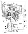
- the lubrication passages 100 may be in fluid communication with a bearing or bearings for providing a lubrication fluid 102 to the bearing or bearings, and may further be positioned adjacent to the bearings which require lubrication, as shown in FIG. 2 .
- lubrication fluid 102 may be flowed through a lubrication passage 100 to a bearing, such as a bearing 92 as shown, to lubricate the bearing.
- Lubrication fluid 102 may, in exemplary embodiments, be a suitable oil for lubricating bearings. Alternatively, however, the lubrication fluid 102 may be any other suitable liquid or gas composition.
- each drainage passage 104 may be in fluid communication with the bearing that was lubricated, such as bearing 92, and may be provided for flowing lubrication fluid 102 therethrough, thus, removing lubrication fluid 102 from the bearing.
- FIGS. 2 and 3 illustrate a plurality of drainage passages 104 defined in a drivetrain 28.
- a drainage passage 104 may be defined partially or wholly in a seal, such as in a labyrinth seal 110, a contact seal, or any other suitable seal.
- Such seals may be provided in the drivetrain 28 to seal various components from one another and/or to generally seal the drivetrain components 28 from the generator 22 components.
- a drainage passage 104 may be defined partially or wholly in the housing 80.
- a drainage passage 104 may be defined in other suitable component of the drivetrain 28.
- the drainage passages 104 may extend in any suitable direction for draining the lubrication fluid 102 from the bearings.
- lubrication fluid 102 may be suctioned from the bearings.
- the creation of a negative pressure environment in at least a portion of the drivetrain 28, such as in the various lubrication passages 100 and drainage passages 104, may prevent pooling and reduce leakage.
- a dry sump 120 may be provided in fluid communication with one or more of the drainage passages 104.
- the dry sump 120 may be configured to suction lubrication fluid 102 from the bearings, such as from bearings 92.
- the dry sump 120 may include, for example, a pump 122.
- the pump 122 may be operable to flow lubrication fluid 102 from the drainage passages 104.
- the pump 122 may created a suctioning, negative pressure environment as discussed above, thus causing the lubrication fluid to flow from the drainage passages 104.
- one or more pipes 124 or other suitable conduits may be provided in the dry sump 120.
- the pipes 124 may be connected to the drainage passages 104, as shown, and may flow the lubrication fluid 102 from the drainage passages 104 therethrough.
- the dry sump 120 may further include a reservoir 126.
- the reservoir 126 may hold excess lubrication fluid 102 after the lubrication fluid 102 is flowed from the bearings. Alternatively, the excess lubrication fluid 102 may be otherwise discarded from the drivetrain 28 in any suitable fashion.
- the lubrication fluid 102 flowed from the bearing may be recirculated to the bearing.
- the dry sump 120 may include further piping or other suitable conduits (shown schematically as reference numeral 128) extending between the reservoir 126, pump 122, and lubrication passages 100.
- the pump 122 may further be operable to flow lubrication fluid 102 through this piping or other conduits to the lubrication passages 100 and bearings, such that lubrication fluid 102 is recirculated to or within the drivetrain 28 as desired or required.
- the drivetrain 28 may prevent both pooling and leakage.
- Such novel and advantageous design may thus result in less losses due to churning of the various components of the drivetrain 28, such as the bearings, higher resulting efficiency of the drivetrain 28, decreased leakage, decreased temperatures of the various components of the drivetrain 28, and decreased noise of the various components of the drivetrain 28.
- such novel and advantageous design may allow for higher speeds, loads, stiffnesses, and operable lives of the various components of the drivetrain 28, such as the bearings.
- the present disclosure is further directed to a method for lubrication a bearing, such as a bearing 92 or a bearing 90.
- the method includes, for example the step of flowing lubrication fluid 102 to the bearing.
- the method further includes the step of suctioning the lubrication fluid from the bearing.
- the suctioning step includes, for example, operating a dry sump 120 to suction the lubrication fluid from the bearing.
- the method includes recirculating the lubrication fluid 102.
Applications Claiming Priority (1)
| Application Number | Priority Date | Filing Date | Title |
|---|---|---|---|
| US13/232,561 US20120141270A1 (en) | 2011-09-14 | 2011-09-14 | Drivetrain and method for lubricating bearing in wind turbine |
Publications (2)
| Publication Number | Publication Date |
|---|---|
| EP2570663A2 true EP2570663A2 (de) | 2013-03-20 |
| EP2570663A3 EP2570663A3 (de) | 2013-11-13 |
Family
ID=46162391
Family Applications (1)
| Application Number | Title | Priority Date | Filing Date |
|---|---|---|---|
| EP12183115.0A Withdrawn EP2570663A3 (de) | 2011-09-14 | 2012-09-05 | Antriebsstrang und Verfahren zur Lagerschmierung in einer Windturbine |
Country Status (3)
| Country | Link |
|---|---|
| US (1) | US20120141270A1 (de) |
| EP (1) | EP2570663A3 (de) |
| CN (1) | CN102996369A (de) |
Cited By (2)
| Publication number | Priority date | Publication date | Assignee | Title |
|---|---|---|---|---|
| EP2619453A1 (de) * | 2010-09-21 | 2013-07-31 | XEMC Darwind BV | Windturbine mit ölschmierung |
| US11396865B2 (en) | 2016-07-05 | 2022-07-26 | Vestas Wind Systems A/S | Wind turbine generator with an electric generator bearing assembly |
Families Citing this family (23)
| Publication number | Priority date | Publication date | Assignee | Title |
|---|---|---|---|---|
| EP2617994B1 (de) * | 2012-01-20 | 2021-01-13 | ZF Wind Power Antwerpen NV | Antriebsstrang für eine Windenergieanlage |
| JP6185054B2 (ja) * | 2012-06-10 | 2017-08-23 | ヴェスタス ウィンド システムズ エー/エス | 風力タービンの主軸受機構 |
| ES2761952T3 (es) * | 2012-08-21 | 2020-05-21 | Skf Ab | Disposición de eje de rotor de aerogenerador |
| US9422979B2 (en) * | 2013-04-15 | 2016-08-23 | Hamilton Sundstrand Corporation | Standpipe assembly |
| US8992090B1 (en) * | 2013-04-16 | 2015-03-31 | Florida Turbine Technologies, Inc. | Air drained bearing compartment with oil shield |
| WO2015101288A1 (zh) * | 2013-12-31 | 2015-07-09 | 南车戚墅堰机车车辆工艺研究所有限公司 | 一体化的半直驱风力发电机传动链及其所用齿轮箱 |
| EP3012473B1 (de) * | 2014-10-24 | 2017-12-13 | Aktiebolaget SKF | Lagereinheit und Verfahren zum Betrieb und zur Wartung solch einer Lagereinheit |
| DE102014227039A1 (de) * | 2014-12-30 | 2016-06-30 | Siemens Aktiengesellschaft | Schmiermittelauffangeinrichtung |
| US10247297B2 (en) * | 2017-01-18 | 2019-04-02 | General Electric Company | Apparatus for a gearbox with multiple scavenge ports |
| US11248589B2 (en) | 2017-02-21 | 2022-02-15 | Vestas Wind Systems A/S | Wind turbine main rotor arrangement with integrated lubrication facility |
| US10495185B2 (en) * | 2017-03-06 | 2019-12-03 | Fairfield Manufacturing Company, Inc. | Planetary wheel drive using bushings |
| US10066735B1 (en) | 2017-03-06 | 2018-09-04 | Fairfield Manufacturing Company, Inc. | Planetary wheel drive single wall lugged output carrier |
| DE102017128951A1 (de) * | 2017-12-06 | 2019-06-06 | Thyssenkrupp Ag | Wälzlageranordnung und Verfahren |
| DE102017128949A1 (de) * | 2017-12-06 | 2019-06-06 | Thyssenkrupp Ag | Wälzlageranordnung und Verfahren |
| CN111919052B (zh) | 2018-04-12 | 2022-06-24 | 维斯塔斯风力系统有限公司 | 具有低摩擦径向轴密封件的风力涡轮机传动系部件 |
| CN108980217B (zh) * | 2018-09-27 | 2023-10-20 | 杭州前进齿轮箱集团股份有限公司 | 一种风电齿轮箱高速轴轴承降温装置 |
| US11313455B2 (en) * | 2018-10-05 | 2022-04-26 | Textron Innovations Inc. | Aircraft gearbox lubrication system with multiple lubrication subsystems |
| BR102019003809B1 (pt) * | 2019-02-25 | 2024-03-12 | Cnh Industrial Brasil Ltda | Conjunto extrator de resíduos para máquinas agrícolas e máquina colheitadeira |
| DK4143450T3 (da) * | 2020-04-28 | 2024-04-22 | thyssenkrupp rothe erde Germany GmbH | Rotorleje til et vindenergianlæg og vindenergianlæg |
| BE1028243B1 (de) * | 2020-04-28 | 2021-11-29 | Thyssenkrupp Ag | Rotorlager für eine Windenergieanlage und Windenergieanlage |
| CN112283054B (zh) * | 2020-10-12 | 2024-01-30 | 国家电投集团广西金紫山风电有限公司 | 一种废油排出控制方法、装置、设备及介质 |
| EP4102068B1 (de) * | 2021-06-09 | 2024-03-13 | Ørsted Wind Power A/S | Vorrichtung zur schmierfettextraktion bei einem windturbinengenerator und verfahren zur schmierfettextraktion |
| CN113339408B (zh) * | 2021-07-08 | 2022-05-31 | 哈电风能有限公司 | 发电机单轴承润滑密封结构及发电机组 |
Family Cites Families (9)
| Publication number | Priority date | Publication date | Assignee | Title |
|---|---|---|---|---|
| US2996146A (en) * | 1958-10-13 | 1961-08-15 | Gen Motors Corp | Lubrication system |
| JPS60159498A (ja) * | 1984-01-31 | 1985-08-20 | Mitsubishi Heavy Ind Ltd | 軸受装置 |
| JPH04121371U (ja) * | 1991-04-18 | 1992-10-29 | 東洋電機製造株式会社 | 電動機の軸受構造 |
| US5271676A (en) * | 1992-07-30 | 1993-12-21 | General Electric Company | Combination package tilt pad journal bearing/dual self equalizing thrust bearings, with hydrostatic lift provisions |
| WO2003029671A1 (en) * | 2001-10-03 | 2003-04-10 | Vestas Wind Systems A/S | Apparatus for lubricating the bearings of an electrical power generator in a wind turbine |
| US20080044279A1 (en) * | 2006-08-17 | 2008-02-21 | Orlowski David C | Adaptor Frame |
| US8298115B2 (en) * | 2008-07-10 | 2012-10-30 | General Electric Company | Wind turbine transmission assembly |
| DK2385248T3 (da) * | 2010-05-06 | 2012-09-24 | Siemens Ag | Leje, især til en vindturbine |
| US9903345B2 (en) * | 2010-09-21 | 2018-02-27 | Xemc Darwind B.V. | Wind turbine with oil lubrication |
-
2011
- 2011-09-14 US US13/232,561 patent/US20120141270A1/en not_active Abandoned
-
2012
- 2012-09-05 EP EP12183115.0A patent/EP2570663A3/de not_active Withdrawn
- 2012-09-14 CN CN2012103422453A patent/CN102996369A/zh active Pending
Non-Patent Citations (1)
| Title |
|---|
| None |
Cited By (3)
| Publication number | Priority date | Publication date | Assignee | Title |
|---|---|---|---|---|
| EP2619453A1 (de) * | 2010-09-21 | 2013-07-31 | XEMC Darwind BV | Windturbine mit ölschmierung |
| US9903345B2 (en) | 2010-09-21 | 2018-02-27 | Xemc Darwind B.V. | Wind turbine with oil lubrication |
| US11396865B2 (en) | 2016-07-05 | 2022-07-26 | Vestas Wind Systems A/S | Wind turbine generator with an electric generator bearing assembly |
Also Published As
| Publication number | Publication date |
|---|---|
| US20120141270A1 (en) | 2012-06-07 |
| EP2570663A3 (de) | 2013-11-13 |
| CN102996369A (zh) | 2013-03-27 |
Similar Documents
| Publication | Publication Date | Title |
|---|---|---|
| EP2570663A2 (de) | Antriebsstrang und Verfahren zur Lagerschmierung in einer Windturbine | |
| EP2461030A2 (de) | Antriebsstrang für einen Generator in einer Windturbine | |
| US10711877B2 (en) | Passive lubrication system for gas turbine engine gearbox during wind milling | |
| EP2565475A2 (de) | Getriebe für eine Windturbine | |
| EP3056763A1 (de) | Getriebeschmiersystem | |
| CN202579057U (zh) | 大功率风力发电机增速齿轮箱 | |
| EP2472110A2 (de) | Antriebsstrang für einen Generator in einer Windturbine | |
| EP3530939A1 (de) | Ersatzverfahren für radialdichtungen von windturbinenhauptlagern | |
| CN102147005A (zh) | 风力发电机齿轮箱的输入端 | |
| US20140084588A1 (en) | Gas bearing supported turbomachine with reduction gear assembly | |
| CN201367988Y (zh) | 下风向型风力发电机增速齿轮箱 | |
| EP3482073B1 (de) | Eine windturbine mit einer lageranordnung des elektrischen generators | |
| JP4969708B1 (ja) | 再生エネルギー型発電装置及び油圧ポンプの取付け方法 | |
| US11085421B2 (en) | Planet carrier of a wind turbine gearbox with improved lubricant path | |
| CN201126005Y (zh) | 下风向型风力发电机增速齿轮箱 | |
| CN109751207B (zh) | 用于风力涡轮机的轴承的润滑系统和方法及传动系组件 | |
| CN213744563U (zh) | 水轮发电机导轴承冷却结构 | |
| CN202040015U (zh) | 风力发电机齿轮箱的输入端 | |
| CN201367989Y (zh) | 大功率风力发电机增速齿轮箱 | |
| CN203948606U (zh) | 大功率风力发电机试验台齿轮箱 | |
| CN202176705U (zh) | 风电齿轮箱行星部件中润滑结构的改进 | |
| CN113357343A (zh) | 一种发电机轴系集成于齿轮箱的结构 | |
| KR101686799B1 (ko) | 수차 축과 발전기 회전자 일체형 소수력 발전장치 | |
| WO2020008238A1 (en) | Shaft-less turbo-machines & propulsion systems | |
| WO2024083253A1 (zh) | 一种风电机齿轮箱润滑装置及齿轮箱 |
Legal Events
| Date | Code | Title | Description |
|---|---|---|---|
| PUAI | Public reference made under article 153(3) epc to a published international application that has entered the european phase |
Free format text: ORIGINAL CODE: 0009012 |
|
| AK | Designated contracting states |
Kind code of ref document: A2 Designated state(s): AL AT BE BG CH CY CZ DE DK EE ES FI FR GB GR HR HU IE IS IT LI LT LU LV MC MK MT NL NO PL PT RO RS SE SI SK SM TR |
|
| AX | Request for extension of the european patent |
Extension state: BA ME |
|
| PUAL | Search report despatched |
Free format text: ORIGINAL CODE: 0009013 |
|
| AK | Designated contracting states |
Kind code of ref document: A3 Designated state(s): AL AT BE BG CH CY CZ DE DK EE ES FI FR GB GR HR HU IE IS IT LI LT LU LV MC MK MT NL NO PL PT RO RS SE SI SK SM TR |
|
| AX | Request for extension of the european patent |
Extension state: BA ME |
|
| RIC1 | Information provided on ipc code assigned before grant |
Ipc: F16C 33/66 20060101ALI20131008BHEP Ipc: F03D 11/02 20060101AFI20131008BHEP |
|
| STAA | Information on the status of an ep patent application or granted ep patent |
Free format text: STATUS: THE APPLICATION IS DEEMED TO BE WITHDRAWN |
|
| 18D | Application deemed to be withdrawn |
Effective date: 20140514 |