EP2570570A2 - Schwimmbeckenreinigungsroboter - Google Patents
Schwimmbeckenreinigungsroboter Download PDFInfo
- Publication number
- EP2570570A2 EP2570570A2 EP12184101A EP12184101A EP2570570A2 EP 2570570 A2 EP2570570 A2 EP 2570570A2 EP 12184101 A EP12184101 A EP 12184101A EP 12184101 A EP12184101 A EP 12184101A EP 2570570 A2 EP2570570 A2 EP 2570570A2
- Authority
- EP
- European Patent Office
- Prior art keywords
- fluid path
- impeller
- housing
- pool
- cleaning robot
- Prior art date
- Legal status (The legal status is an assumption and is not a legal conclusion. Google has not performed a legal analysis and makes no representation as to the accuracy of the status listed.)
- Granted
Links
Images



Classifications
-
- E—FIXED CONSTRUCTIONS
- E04—BUILDING
- E04H—BUILDINGS OR LIKE STRUCTURES FOR PARTICULAR PURPOSES; SWIMMING OR SPLASH BATHS OR POOLS; MASTS; FENCING; TENTS OR CANOPIES, IN GENERAL
- E04H4/00—Swimming or splash baths or pools
- E04H4/14—Parts, details or accessories not otherwise provided for
- E04H4/16—Parts, details or accessories not otherwise provided for specially adapted for cleaning
- E04H4/1654—Self-propelled cleaners
-
- E—FIXED CONSTRUCTIONS
- E04—BUILDING
- E04H—BUILDINGS OR LIKE STRUCTURES FOR PARTICULAR PURPOSES; SWIMMING OR SPLASH BATHS OR POOLS; MASTS; FENCING; TENTS OR CANOPIES, IN GENERAL
- E04H4/00—Swimming or splash baths or pools
- E04H4/14—Parts, details or accessories not otherwise provided for
- E04H4/16—Parts, details or accessories not otherwise provided for specially adapted for cleaning
- E04H4/1618—Hand-held powered cleaners
- E04H4/1636—Suction cleaners
-
- E—FIXED CONSTRUCTIONS
- E04—BUILDING
- E04H—BUILDINGS OR LIKE STRUCTURES FOR PARTICULAR PURPOSES; SWIMMING OR SPLASH BATHS OR POOLS; MASTS; FENCING; TENTS OR CANOPIES, IN GENERAL
- E04H4/00—Swimming or splash baths or pools
- E04H4/14—Parts, details or accessories not otherwise provided for
- E04H4/16—Parts, details or accessories not otherwise provided for specially adapted for cleaning
- E04H4/1654—Self-propelled cleaners
- E04H4/1672—Connections to the pool water circulation system
Definitions
- This invention relates to devices for cleaning swimming pools, basins, and the like. More particularly, the invention relates to an electric robot being able to clean the swimming pool automatically.
- cleaning robots Different types exist, and particularly known are cleaning robots whose suction is connected to the suction device of the pool filtration system and depends on the latter, and cleaning robots equipped with a pump that is independent in relation to the pool filtration system.
- a robot that uses the filtration system of the pool is disclosed for example in US patent application US2009/307854 .
- a robot that is equipped with a pump and has an internal filtration system is disclosed for example in US patent application US2007/028405 .
- a pool cleaning robot that is marketed under the name WEDA B680.
- This robot has an internal pump and a filter bag which is connectable to its impeller outlet.
- This robot can also be connected to an external filtration system such as the filtration system of the pool by removing the filter bag, and directing the impeller outlet to be filtered by the external filtration system.
- the presently disclosed subject matter provides a pool cleaning robot which can filter the water of the pool by using of an internal or an external suction and filtering system, according to different needs and parameters (e.g., the type of the debris in the water, time, and availability of the filtering systems).
- a pool cleaning robot comprising: a housing having a housing bottom and a housing top surface; an impeller and a motor configured to operate the impeller, both mounted within the housing; at least one filter compartment formed within the housing configured for accommodating a filter unit therein; an impeller outlet formed in the housing top surface; at least one additional outlet other than the impeller outlet formed in the housing top surface and configured for being fluidly connected to an external suction and filtering system; at least one bottom inlet formed in the housing bottom configured for a first fluid communication with the impeller outlet via the filter unit, thereby defining a first fluid path; and at least one bottom inlet formed in the housing bottom configured for a second fluid communication with the additional outlet via a second fluid path at least partially different from the first fluid path.
- the second fluid path constitutes a part of an external suction and filtering fluid path created when the additional outlet is fluidly connected to an external suction and filtering system.
- a pool cleaning robot comprising: a housing having a housing bottom and a housing top surface; an impeller and a motor configured to operate the impeller, both mounted within the housing; at least one filter compartment formed within said housing configured for accommodating a filter unit therein; an impeller outlet formed in said housing top surface; at least one additional outlet other than the impeller outlet formed in said housing top surface and configured for being fluidly connected to an external suction and filtering system; at least one first bottom inlet formed in said housing bottom configured for a first fluid communication with the impeller outlet via said filter unit, thereby defining a first fluid path; and at least one second bottom inlet formed in said housing bottom configured for a second fluid communication with said additional outlet via a second fluid path at least partially different from the first fluid path.
- the robot according to embodiments described herein can further comprise an arrangement for selecting or mixing between the first fluid communication and the second fluid communication.
- the filter compartment can be configured to accommodate an adapter unit having an interior portion which constitutes a part of the second fluid path.
- the interior portion of the adapter unit can be disposed between a first and a second end of the adapter unit.
- the first end of the adapter unit can be configured for fluidly communicating with the bottom inlet of the second fluid path, and the second end of the adapter unit can be configured for fluidly communicating with the additional outlet.
- the arrangement for selecting or mixing between the first fluid communication and the second fluid communication can be provided by the filter unit and the adapter unit being interchangeably accommodated within the filter compartment.
- the arrangement can further provided by the additional outlet being configured for being opened and closed for allowing and preventing the second fluid communication, respectively.
- the robot can further comprise a hose adapter configured for fluidly connecting the additional outlet to a hose connectable to the external suction and filtering system.
- the external suction and filtering fluid path can further be defined by this hose.
- the hose adapter can include a swivel mechanism configured for preventing swivel of said hose around itself.
- the robot can be operated by an electric supply source via an electric cable.
- the robot can comprise at least one holder configured for holding the electric cable and the hose in proximity to each other and preventing their swivel around each other.
- the holder can comprise: an aperture for allowing insertion of said cable therethrough and free rotation of said cable therein; and a grasper configured for detachably attaching to the hose.
- the robot can be configured to be operated via the second and the third fluid communications, simultaneously.
- the arrangement for selecting or mixing between the first and a combination of the second with the third fluid paths can be provided by the additional inlet which is configured for being opened and closed for allowing and preventing said third fluid communication, respectively.
- the additional inlet and outlet can be disposed at a common opening formed within the housing top surface.
- the common opening can comprise a door configured for allowing and preventing the second and third fluid communication by being opened and closed, correspondingly.
- the additional inlet can be formed at the common opening around the additional outlet.
- the bottom inlet of the first fluid path can constitute the bottom inlet of the second fluid path
- the filter unit can have a filter unit interior at least a part of which can be configured to constitute at least a part of the first and the second fluid paths, while the third fluid path is obstructed (if it exists).
- the filter unit can comprise a filter unit opening configured to fluidly communicate between the filter interior and the additional outlet.
- the fluid communication between the filter interior and the additional outlet can be configured to allow extraction of debris from the filter interior via the second fluid path.
- the first and second fluid paths can be operative simultaneously, during the operation of the robot.
- the first and second fluid paths can be operative independently from each other.
- the robot can comprise a driving unit having at least one electric motor configured for moving the robot within the pool.
- the driving unit can be operated by an electric supply source, and can comprise a main controller configured to control the operation of the motor during operation of the robot via the first fluid path, and during operation of the robot via a combination of the second and the third fluid paths.
- the at least one bottom inlet can constitute at least a first and a second bottom inlet, one of which is sealable for fluid communication by a sealing member when the second and third fluid communications are selected.
- a pool cleaning robot comprising: a housing having a housing bottom and a housing top surface; an impeller and a motor configured to operate the impeller, both mounted within the housing; an impeller outlet formed in the housing top surface; at least one bottom inlet formed in the housing bottom configured for a first fluid communication with the impeller outlet via the filter unit, thereby defining a first fluid path; and at least one additional inlet formed in the housing top surface and configured for a third fluid communication with the impeller outlet, thereby defining a third fluid path.
- the first and the third fluid communications can be configured to generate a thrust force that biases the housing toward a pool surface which the housing bottom faces during operation of the robot.
- a pool cleaning robot comprising: a housing having a housing bottom and a housing top surface; an impeller and a motor configured to operate the impeller, both mounted within the housing; a first and a second filter compartments formed within the housing, each configured for accommodating a filter unit therein; the motor being disposed between the first and second filter compartments; an impeller outlet formed in the housing top surface; an additional outlet other than the impeller outlet formed in the housing top surface proximal to the first filter compartment and configured for being fluidly connected to an external suction and filtering system; and a first and a second bottom inlets formed in the housing bottom, each configured to be in fluid communication with the first and the second filter compartments and configured for a first fluid communication with the impeller outlet via the filter units, thereby defining a first fluid path.
- the first bottom inlet can be configured for a second fluid communication with the additional outlet via a second fluid path at least partially different from the first fluid path.
- the second fluid path can constitute a part of an external suction and filtering fluid path created when the additional outlet is fluidly connected to an external suction and filtering system.
- the robot can comprise an additional inlet formed in the housing top surface and configured for a third fluid communication with the impeller outlet, thereby defining a third fluid path.
- the third fluid communication can generate a thrust force that biases the housing toward a pool surface adjacent to the housing bottom.
- the first fluid communication can also generate a thrust force that biases the housing toward a pool surface adjacent to the housing bottom.
- the robot can further comprise an arrangement for selecting or mixing between the first and a combination of the second with the third fluid communications.
- the arrangement can be provided by the additional outlet being configured for being opened and closed for allowing and preventing said second fluid communication, respectively.
- the additional inlet and outlet can be disposed at a common opening formed within the housing top surface.
- the common opening can comprise a door configured for allowing and preventing the second and third fluid communications, by being opened and closed, correspondingly.
- the additional inlet can be formed at the common opening around the additional outlet.
- the first filter compartment can be configured to accommodate an adapter unit having an interior portion which constitutes a part of the second fluid path.
- the interior portion of the adapter unit can be disposed between a first and a second end of the adapter unit.
- the first end of the adapter unit can fluidly communicate with the first bottom inlet, and the second end of the adapter unit can fluidly communicate with the additional outlet.
- the arrangement for selecting or mixing between the first fluid communication and the second fluid communication can be provided by the filter unit and the adapter unit being interchangeably accommodated within the filter compartment.
- the robot can further comprise a hose adapter configured for fluidly connecting the additional outlet to a hose connectable to the external suction and filtering system.
- the hose adapter can include a swivel mechanism configured for preventing swivel of said hose around itself.
- a kit for cleaning a pool comprising a pool cleaning robot, an adapter unit, and a hose.
- the pool cleaning robot comprising: a housing having a housing bottom and a housing top surface; an impeller and a motor configured to operate the impeller, both mounted within the housing; at least one filter compartment formed within the housing configured for accommodating a filter unit and the configured for accommodating the adapter unit therein; an impeller outlet formed in the housing top surface; at least one additional outlet other than the impeller outlet formed in the housing top surface and configured for being fluidly connected to an external suction and filtering system via the hose; at least one bottom inlet formed in the housing bottom configured for a first fluid communication with the impeller outlet via the filter unit, thereby defining a first fluid path; and at least one bottom inlet formed in the housing bottom configured for a second fluid communication with the additional outlet via a second fluid path at least partially different from the first fluid path and via the adapter unit, the second fluid path constituting a part
- the holder can comprise: an aperture for allowing insertion of the cable therethrough and free rotation of the cable therein; and a grasper configured for detachably attaching to the hose.
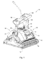
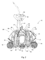
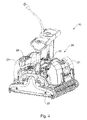
- the housing 10 further includes an impeller outlet 30 which is formed in the housing top surface 24, and a first and second bottom inlets 32 and 34 which are formed in the housing bottom 22. As shown in Fig. 3 , the first and the second bottom inlets 32 and 34 are in fluid communication with the first and the second filter compartments 26 and 28, and with the first and the second filter units 27 and 29, correspondingly. In the configuration of the robot 10 according to Figs. 1 to 3 , in which the internal filtering system is used, the first and the second bottom inlets 32 and 34 are in a first fluid communication with the impeller outlet 30 via the first and the second filter units 27 and 29, correspondingly, thereby defining a first fluid path 51 (shown in Fig. 2 ).
- the impeller 44 which is operated by the impeller motor, draws water and debris from the floor or sidewall of the pool via the first fluid path, i.e., from the first and the second water inlets 32 and 34 through the first and the second filters 27 and 29 towards the impeller outlet 30.
- the clean water is expelled through the impeller outlet 30.
- this process generates a thrust force that biases the robot 10 toward the surface of the pool. This thrust force keeps the robot proximal to the pool's surface to as to clean the pool's floor and to climb on the pool's wall and clean it.
- This operation is generally similar to the operation of known electrically powered robots, which have internal filtering system, such as the robots which are disclosed in US2009/0045110 and in US2010/0306931 .
- the motors 42 rotate the movement belts 12 which rotate the two main brushes 14 and the auxiliary brush 15. This provided to the robot 10 the ability to move and to clear the pool's surface by the brushes.
- the first and second covers 21 and 23 can be pivotally opened so as to extract the filter units 27 and 29 out of their filter compartment 26 and 28, correspondingly.
- the connection of the robot 10 to the external suction and filtering system and its operation when connected to this system are detailed below.
- the additional outlet 74 is used for pumping water with debris from an area underneath the housing bottom 22 to the external suction and filtering system. When the water with debris is received within the external suction and filtering system, it is filtered therein and clean water is returned to the pool.
- the first bottom inlet 32 is used for a second fluid communication with the additional outlet 74 via a second fluid path 52 (which is different from the first fluid path 51).
- the second fluid path 52 constitutes a part of an external suction and filtering fluid path 54 which is created when the additional outlet 74 is fluidly connected to the external suction and filtering system.
- the door 76 is opened, and an adapter unit 80 (shown in Figs. 6 and 7 ) is inserted into the first filter compartment 26.
- the adapted unit 80 has an interior portion which is configured to fluidly interconnect between the additional outlet 74 and the bottom inlet 32, thereby constitute a part of the second fluid path 52.
- the second bottom inlet 34 has to be sealed so as to prevent entrance of water into the second filter compartment 28. This sealing is performed by inserting a sealing member 35 (shown in Figs. 6 and 8 ) into the second bottom inlet 34.
- the motors of the robot, and/or its controller may not know which filtering system is used, because in both cases the motors of robot which are responsible with its movement and for the rotation of the impeller may continue to operate at the same manner indifferently which filtering system is used.
- FIG. 9 schematically illustrates a holder 100 having configured for holding the electric cable 41 and the hose 92 in proximity to each other.
- a plurality of holders 100 can be used for holding the electric cable 41 and the hose 92 together.
- the holder 100 comprises: an aperture 105 configured for allowing insertion of the electric cable 41 therethrough and free rotation of this cable therein; and a grasper 110 configured for detachably attaching to the hose 92.
- the hose 92 will no swivel within the grasper 110 due to the swivel mechanism 91 and a strong gripping of the hose 92 by the grasper 110.
- the robot 210 comprises a housing 220 which has a housing bottom 222 and a housing top surface 224 having a first cover 221 and a second cover 223, and a driving unit 240 having an impeller 244 which is connected to an impeller motor (not shown) that rotates the impeller in operation.
- the driving unit 240 is sealably disposed within the housing 220, and can be operated by being connected to an electric power source (not shown) via an electric cable 241.
- the driving unit 240 also includes a main controller (not shown) which can be programmed to control the operation of the robot, and specifically the operation of the robot's motors.
- the main controller can be programmed to perform scanning of the pool according to one of several algorithms.
- each of the filter compartments 226 and 228 accommodates a first filter unit 227 and a second filter unit 229, correspondingly.
- the first and the second filter units 227 and 229 constitute a part of the internal filtering system by filtering the pool's water which passes therethrough while being pumped by the impeller 244.
- the filter units 227 and 229 are made of a rigid frame, and can be extracted from the robot 210 for cleaning, replacement, and for using the external suction and filtering system instead of the internal filtering system.
- the housing 210 further includes an impeller outlet 230 which is formed in the housing top surface 224, and a first and second bottom inlets 232 and 234 which are formed in the housing bottom 222. As shown in Fig. 10 , the first and the second bottom inlets 232 and 234 are in fluid communication with the first and the second filter compartments 226 and 228, and with the first and the second filter units 227 and 229, correspondingly. In the configuration of the robot 210, in which the internal filtering system is used, the first and the second bottom inlets 232 and 234 are in a first fluid communication with the impeller outlet 230 via the first and the second filter units 227 and 229, correspondingly, thereby defining a first fluid path 251.
- the robot's 220 operation for cleaning the pool by the internal filtering system it can be fluidly connected to an external suction and filtering system for simultaneously and/or independently extracting the debris that is collected in the filter unit(s) of the internal filtering system.
- This operation of the external suction and filtering system can be used for emptying the filter unit(s) of the internal filtering system without extracting the robot 220 from the pool and without extracting the filter unit(s) from the robot in order to clean them.
- the filter unit 227 has a filter unit interior 233 a part of which constitutes a part of the first fluid path 251 and also a part of a second fluid path 252.
- the second fluid path 252 is defined between the first bottom inlet 232, the filter unit interior 233, a filter unit opening 265, an additional outlet 274, a hose 292, and an external suction and filtering system (not shown).
- the second fluid path 252 can be established by opening a door 276, connecting a hose adapter 279 to the filter unit opening 265 in the additional outlet 274, and connecting the hose 292 to the hose adapter 279.
- the hose adapter 279 includes a swivel mechanism 280 which is configured for preventing swivel of the hose 292 around itself.
- the external suction and filtering system can be one integrated unit which collects the debris from the robot 10 by pumping it, filters the water from the debris, and return the filtered water to the pool.
- the external suction and filtering system can be divided to two parts: a first part (e.g., a debris collecting bag) that collects the massive debris (e.g., leaves) from the filter unit(s) of the robot, and a second part that is responsible for the suction of the debris from the robot, and optionally filtration of the water and returning it to the pool.
- the above described operation of the external suction and filtering system for emptying the filter unit of the robot 210 can be controlled by a timer (not shown) that is preprogrammed to be operated according to predetermined sequences of time.
Landscapes
- Engineering & Computer Science (AREA)
- Architecture (AREA)
- Civil Engineering (AREA)
- Structural Engineering (AREA)
- Structures Of Non-Positive Displacement Pumps (AREA)
- Cleaning In General (AREA)
Applications Claiming Priority (1)
| Application Number | Priority Date | Filing Date | Title |
|---|---|---|---|
| IL215115A IL215115A (en) | 2011-09-13 | 2011-09-13 | Pool cleaning robot |
Publications (3)
| Publication Number | Publication Date |
|---|---|
| EP2570570A2 true EP2570570A2 (de) | 2013-03-20 |
| EP2570570A3 EP2570570A3 (de) | 2016-08-17 |
| EP2570570B1 EP2570570B1 (de) | 2018-07-11 |
Family
ID=45595781
Family Applications (1)
| Application Number | Title | Priority Date | Filing Date |
|---|---|---|---|
| EP12184101.9A Active EP2570570B1 (de) | 2011-09-13 | 2012-09-12 | Schwimmbeckenreinigungsroboter |
Country Status (6)
| Country | Link |
|---|---|
| US (1) | US9133639B2 (de) |
| EP (1) | EP2570570B1 (de) |
| AT (1) | AT13531U1 (de) |
| DE (1) | DE202011051889U1 (de) |
| ES (1) | ES2689959T3 (de) |
| IL (1) | IL215115A (de) |
Cited By (2)
| Publication number | Priority date | Publication date | Assignee | Title |
|---|---|---|---|---|
| DE102014012377B3 (de) * | 2014-08-20 | 2016-01-07 | Tosstec Kg | Unterwasser-Reinigungsmaschine |
| EP4442933A1 (de) * | 2023-04-04 | 2024-10-09 | Shenzhen Aiper Intelligent Co., Ltd | Reinigungsroboter für schwimmbecken |
Families Citing this family (39)
| Publication number | Priority date | Publication date | Assignee | Title |
|---|---|---|---|---|
| WO2014097304A1 (en) * | 2012-12-22 | 2014-06-26 | Maytronics Ltd. | Autonomous pool cleaning robot |
| US9259130B2 (en) | 2012-06-04 | 2016-02-16 | Pentair Water Prool and Spa, Inc. | Pool cleaner light module |
| CA2883504A1 (en) | 2012-09-04 | 2014-03-13 | Pentair Water Pool And Spa, Inc. | Pool cleaner generator module with magnetic coupling |
| US20160047135A1 (en) * | 2012-11-20 | 2016-02-18 | Aqua Products, Inc. | Brush assembly for self-propelled pool and tank cleaner |
| US20140137343A1 (en) * | 2012-11-20 | 2014-05-22 | Aqua Products, Inc. | Pool or tank cleaning vehicle with a powered brush |
| EP2743429B1 (de) * | 2012-12-17 | 2016-10-05 | Upward Sales Limited | Automatisches Poolreinigungsfahrzeug mit Scheuervorrichtung |
| EP2971411A4 (de) | 2013-03-13 | 2017-04-19 | Pentair Water Pool and Spa, Inc. | Doppelpaddelmechanismus für schwimmbeckenreiniger |
| US10435904B2 (en) | 2013-10-13 | 2019-10-08 | Maytronics Ltd. | Pool cleaning robot having a filtering unit and a sensor |
| US10094130B2 (en) * | 2013-11-08 | 2018-10-09 | Water Technology, Llc | Submersible electric-powered leaf vacuum cleaner |
| US11091925B2 (en) | 2013-11-08 | 2021-08-17 | Water Technology Llc | Submersible electric-powered leaf vacuum cleaner |
| FR3019575B1 (fr) | 2014-04-04 | 2016-11-04 | Zodiac Pool Care Europe | Appareil nettoyeur de piscine a dispositif de filtration extractible |
| MX2016015679A (es) * | 2014-05-30 | 2017-05-15 | Ingenieria Y Marketing S A | Limpiador de fondos y paredes. |
| US9885196B2 (en) | 2015-01-26 | 2018-02-06 | Hayward Industries, Inc. | Pool cleaner power coupling |
| EP3250327B1 (de) * | 2015-01-26 | 2022-09-28 | Hayward Industries, Inc. | Schwimmbadreiniger mit hydrozyklonischem partikelabscheider und/oder sechswalzenantriebssystem |
| US10927559B2 (en) * | 2016-04-04 | 2021-02-23 | Maytronics Ltd. | Pool cleaning robot having a filtering unit and a sensor |
| EP3318702B1 (de) | 2016-11-03 | 2020-06-24 | Maytronics Ltd. | Schwimmbeckenreinigungsroboter mit filtrierungseinheit und einem sensor |
| US10189490B2 (en) | 2017-05-11 | 2019-01-29 | Hayward Industries, Inc. | Pool cleaner caddy with removable wheel assemblies |
| US10156083B2 (en) | 2017-05-11 | 2018-12-18 | Hayward Industries, Inc. | Pool cleaner power coupling |
| US9896858B1 (en) | 2017-05-11 | 2018-02-20 | Hayward Industries, Inc. | Hydrocyclonic pool cleaner |
| US9885194B1 (en) | 2017-05-11 | 2018-02-06 | Hayward Industries, Inc. | Pool cleaner impeller subassembly |
| US10161153B2 (en) * | 2017-05-11 | 2018-12-25 | Hayward Industries, Inc. | Pool cleaner canister handle |
| US10676950B2 (en) | 2017-05-11 | 2020-06-09 | Hayward Industries, Inc. | Pool cleaner roller latch |
| US9878739B1 (en) | 2017-05-11 | 2018-01-30 | Hayward Industries, Inc. | Pool cleaner modular drivetrain |
| US10214933B2 (en) | 2017-05-11 | 2019-02-26 | Hayward Industries, Inc. | Pool cleaner power supply |
| US10364905B2 (en) | 2017-05-11 | 2019-07-30 | Hayward Industries, Inc. | Pool cleaner check valve |
| US10227081B2 (en) * | 2017-05-11 | 2019-03-12 | Hayward Industries, Inc. | Pool cleaner caddy with retention mechanism |
| ES2987536T3 (es) | 2017-09-19 | 2024-11-15 | Intex Marketing Ltd | Limpiador de piscinas automático con funciones de desplazamiento mejoradas |
| WO2019070452A1 (en) * | 2017-10-04 | 2019-04-11 | Zodiac Pool Systems Llc | METHOD AND SYSTEM FOR CLEANING A SWIMMING POOL WITH THE USE OF AN AUTOMATIC SWIMMING POOL CLEANER AND A SWIMMING POOL CARTOGRAPHY DEVICE |
| ES2834068T3 (es) | 2017-11-03 | 2021-06-16 | Maytronics Ltd | Robot de limpieza de piscinas que tiene una unidad de filtrado y un sensor |
| US11525275B2 (en) * | 2018-07-19 | 2022-12-13 | Scott Jung | Reconfigurable vacuum and skimmer attachment |
| WO2020072200A1 (en) * | 2018-10-02 | 2020-04-09 | Water Technology, Llc | Submersible electric-powered leaf vacuum cleaner |
| CN112112452B (zh) * | 2020-09-15 | 2022-05-17 | 沃姆环境设备启东有限公司 | 可爬墙的泳池清洁机器人 |
| DE102021102621A1 (de) * | 2021-02-04 | 2022-08-04 | Bernd Christof | Abreinigungssystem zum Abreinigen von Partikeln von einer äußeren Oberfläche eines Wasserfahrzeuges oder eines Wasserbauwerkes und mobile Transportvorrichtung |
| CN114753680A (zh) * | 2022-05-23 | 2022-07-15 | 湖北一沐电子科技有限公司 | 一种泳池清洁机器人 |
| USD1022362S1 (en) * | 2022-11-22 | 2024-04-09 | Degrii Co., Ltd. | Swimming pool cleaner with controller |
| EP4670859A1 (de) | 2023-02-23 | 2025-12-31 | Xingmai Innovation Technology (Suzhou) Co., Ltd. | Reinigungsvorrichtung |
| WO2025061196A1 (en) * | 2023-09-22 | 2025-03-27 | Splash Pool & Spa, Inc. | Hybrid pool cleaner with selectable debris retention |
| USD1064471S1 (en) * | 2023-12-28 | 2025-02-25 | Maytronics Ltd. | Detachable fluid distributor for robotic swimming pool cleaner |
| AU2024278571B1 (en) * | 2024-01-05 | 2025-06-26 | Aiper Global Pte. Ltd. | Automatic pool cleaning apparatus |
Citations (3)
| Publication number | Priority date | Publication date | Assignee | Title |
|---|---|---|---|---|
| US20070028405A1 (en) | 2005-08-04 | 2007-02-08 | Efraim Garti | Pool cleaning robot |
| US20090307854A1 (en) | 2008-06-12 | 2009-12-17 | Maytronics Ltd. | Pool cleaning robot |
| US20100306931A1 (en) | 2009-06-04 | 2010-12-09 | Maytronics Ltd. | Pool cleaning robot |
Family Cites Families (19)
| Publication number | Priority date | Publication date | Assignee | Title |
|---|---|---|---|---|
| ZA767474B (en) * | 1976-12-15 | 1978-08-30 | W Rasch | Pool cleaners |
| US5404607A (en) * | 1992-05-11 | 1995-04-11 | Sebor; Pavel | Self-propelled submersible suction cleaner |
| DE4410562A1 (de) * | 1994-03-26 | 1995-09-28 | Eheim Gmbh & Co Kg | Filter für Aquarien |
| US5585010A (en) * | 1995-06-19 | 1996-12-17 | Dockery; Daryl | Aquatic tank filtering system |
| US5725761A (en) * | 1997-02-24 | 1998-03-10 | Phillips; Harold L. | Modular filter / circulation system and traveling main drain for in-ground swimming pools |
| US6039886A (en) * | 1997-06-25 | 2000-03-21 | Henkin; Melvyn L. | Water suction powered automatic swimming pool cleaning system |
| ATE265595T1 (de) * | 1998-09-23 | 2004-05-15 | 3S Systemtechn Ag | Schwimmbadreinrgungsgerät |
| US20080235887A1 (en) * | 1999-01-25 | 2008-10-02 | Aqua Products, Inc. | Pool cleaner with high pressure cleaning jets |
| US6412133B1 (en) * | 1999-01-25 | 2002-07-02 | Aqua Products, Inc. | Water jet reversing propulsion and directional controls for automated swimming pool cleaners |
| FR2818680B1 (fr) * | 2000-12-21 | 2003-04-04 | Zodiac Pool Care Europe | Appareil roulant automoteur nettoyeur de surface immergee |
| US8241430B2 (en) * | 2003-11-04 | 2012-08-14 | Aqua Products, Inc. | Directional control method for dual brush robotic pool cleaners |
| ATE408047T1 (de) * | 2003-11-04 | 2008-09-15 | Aqua Products Inc | Richtungssteuerung für doppelbürsten- schwimmbeckenreinigungsroboter |
| US8007653B2 (en) * | 2004-09-15 | 2011-08-30 | Aquatron, Inc. | Method and appartus for operation of pool cleaner with integral chlorine generator |
| FR2896005B1 (fr) * | 2006-01-11 | 2008-04-04 | Max Roumagnac | Robot nettoyeur de piscine |
| FR2934630B1 (fr) * | 2008-08-04 | 2010-08-13 | Zodiac Pool Care Europe | Appareil roulant nettoyeur de surface immergee a flux d'entrainement orientable. |
| US8343339B2 (en) * | 2008-09-16 | 2013-01-01 | Hayward Industries, Inc. | Apparatus for facilitating maintenance of a pool cleaning device |
| US8709243B2 (en) * | 2008-11-18 | 2014-04-29 | Smartpool Llc | Pool cleaning vehicle having structure for cleaning and sanitizing pool water |
| FR2954377B1 (fr) * | 2009-12-18 | 2015-03-13 | Zodiac Pool Care Europe | Appareil nettoyeur de surface immergee a moteur electrique unique reversible d'entrainement et de pompage |
| US8869337B2 (en) * | 2010-11-02 | 2014-10-28 | Hayward Industries, Inc. | Pool cleaning device with adjustable buoyant element |
-
2011
- 2011-09-13 IL IL215115A patent/IL215115A/en active IP Right Grant
- 2011-10-13 AT ATGM558/2011U patent/AT13531U1/de not_active IP Right Cessation
- 2011-11-08 DE DE201120051889 patent/DE202011051889U1/de not_active Expired - Lifetime
-
2012
- 2012-08-14 US US13/584,837 patent/US9133639B2/en active Active
- 2012-09-12 EP EP12184101.9A patent/EP2570570B1/de active Active
- 2012-09-12 ES ES12184101.9T patent/ES2689959T3/es active Active
Patent Citations (4)
| Publication number | Priority date | Publication date | Assignee | Title |
|---|---|---|---|---|
| US20070028405A1 (en) | 2005-08-04 | 2007-02-08 | Efraim Garti | Pool cleaning robot |
| US20090045110A1 (en) | 2005-08-04 | 2009-02-19 | Maytronics Ltd. | Pool cleaning robot |
| US20090307854A1 (en) | 2008-06-12 | 2009-12-17 | Maytronics Ltd. | Pool cleaning robot |
| US20100306931A1 (en) | 2009-06-04 | 2010-12-09 | Maytronics Ltd. | Pool cleaning robot |
Cited By (2)
| Publication number | Priority date | Publication date | Assignee | Title |
|---|---|---|---|---|
| DE102014012377B3 (de) * | 2014-08-20 | 2016-01-07 | Tosstec Kg | Unterwasser-Reinigungsmaschine |
| EP4442933A1 (de) * | 2023-04-04 | 2024-10-09 | Shenzhen Aiper Intelligent Co., Ltd | Reinigungsroboter für schwimmbecken |
Also Published As
| Publication number | Publication date |
|---|---|
| AT13531U1 (de) | 2014-02-15 |
| IL215115A0 (en) | 2011-11-30 |
| DE202011051889U1 (de) | 2012-01-19 |
| US20130061407A1 (en) | 2013-03-14 |
| US9133639B2 (en) | 2015-09-15 |
| EP2570570A3 (de) | 2016-08-17 |
| EP2570570B1 (de) | 2018-07-11 |
| IL215115A (en) | 2012-05-31 |
| ES2689959T3 (es) | 2018-11-16 |
Similar Documents
| Publication | Publication Date | Title |
|---|---|---|
| US9133639B2 (en) | Pool cleaning robot | |
| AU2019236716B9 (en) | Pool cleaner | |
| US11473325B2 (en) | Swimming pool cleaning device including a removable filter device | |
| US10087646B2 (en) | Filter for swimming pool cleaner | |
| CN100549350C (zh) | 一种手提式电动水池清洁器 | |
| ES2850080T3 (es) | Sistema de limpiador de piscina y estación de anclaje en una piscina | |
| US8661595B2 (en) | Automatic swimming pool cleaning machine | |
| US8307485B2 (en) | Apparatus for facilitating maintenance of a pool cleaning device | |
| ES2742703T3 (es) | Limpiador profundo de despegue | |
| EP2116673B1 (de) | Schwimmbeckenreinigungsfahrzeug mit einem verbesserten Abflusssystem | |
| EP2971407B1 (de) | Automatischer elektrischer schwimmbecken-abwärtsreiniger mit internen pumpen | |
| ES2357619T3 (es) | Limpiador automático para piscinas. | |
| US8632677B2 (en) | Aquarium bottom cleaner system | |
| JP2000140784A (ja) | 水泳プ―ル掃除機 | |
| WO2010003247A1 (en) | Pool vacuum cleaner unit | |
| CN112367838B (zh) | 用于水族箱的水过滤器 | |
| US20200087940A1 (en) | In-Water Suction Cleaner | |
| US20080169247A1 (en) | Spa Cleaner With Pump |
Legal Events
| Date | Code | Title | Description |
|---|---|---|---|
| PUAI | Public reference made under article 153(3) epc to a published international application that has entered the european phase |
Free format text: ORIGINAL CODE: 0009012 |
|
| AK | Designated contracting states |
Kind code of ref document: A2 Designated state(s): AL AT BE BG CH CY CZ DE DK EE ES FI FR GB GR HR HU IE IS IT LI LT LU LV MC MK MT NL NO PL PT RO RS SE SI SK SM TR |
|
| AX | Request for extension of the european patent |
Extension state: BA ME |
|
| PUAL | Search report despatched |
Free format text: ORIGINAL CODE: 0009013 |
|
| AK | Designated contracting states |
Kind code of ref document: A3 Designated state(s): AL AT BE BG CH CY CZ DE DK EE ES FI FR GB GR HR HU IE IS IT LI LT LU LV MC MK MT NL NO PL PT RO RS SE SI SK SM TR |
|
| AX | Request for extension of the european patent |
Extension state: BA ME |
|
| RIC1 | Information provided on ipc code assigned before grant |
Ipc: E04H 4/16 20060101AFI20160714BHEP |
|
| 17P | Request for examination filed |
Effective date: 20170216 |
|
| RBV | Designated contracting states (corrected) |
Designated state(s): AL AT BE BG CH CY CZ DE DK EE ES FI FR GB GR HR HU IE IS IT LI LT LU LV MC MK MT NL NO PL PT RO RS SE SI SK SM TR |
|
| GRAP | Despatch of communication of intention to grant a patent |
Free format text: ORIGINAL CODE: EPIDOSNIGR1 |
|
| INTG | Intention to grant announced |
Effective date: 20180124 |
|
| GRAS | Grant fee paid |
Free format text: ORIGINAL CODE: EPIDOSNIGR3 |
|
| GRAA | (expected) grant |
Free format text: ORIGINAL CODE: 0009210 |
|
| AK | Designated contracting states |
Kind code of ref document: B1 Designated state(s): AL AT BE BG CH CY CZ DE DK EE ES FI FR GB GR HR HU IE IS IT LI LT LU LV MC MK MT NL NO PL PT RO RS SE SI SK SM TR |
|
| REG | Reference to a national code |
Ref country code: GB Ref legal event code: FG4D |
|
| REG | Reference to a national code |
Ref country code: CH Ref legal event code: EP |
|
| REG | Reference to a national code |
Ref country code: AT Ref legal event code: REF Ref document number: 1017037 Country of ref document: AT Kind code of ref document: T Effective date: 20180715 |
|
| REG | Reference to a national code |
Ref country code: IE Ref legal event code: FG4D |
|
| REG | Reference to a national code |
Ref country code: DE Ref legal event code: R096 Ref document number: 602012048307 Country of ref document: DE |
|
| REG | Reference to a national code |
Ref country code: FR Ref legal event code: PLFP Year of fee payment: 7 |
|
| REG | Reference to a national code |
Ref country code: CH Ref legal event code: NV Representative=s name: DENNEMEYER AG, CH |
|
| REG | Reference to a national code |
Ref country code: SE Ref legal event code: TRGR |
|
| REG | Reference to a national code |
Ref country code: NL Ref legal event code: MP Effective date: 20180711 |
|
| REG | Reference to a national code |
Ref country code: ES Ref legal event code: FG2A Ref document number: 2689959 Country of ref document: ES Kind code of ref document: T3 Effective date: 20181116 |
|
| REG | Reference to a national code |
Ref country code: LT Ref legal event code: MG4D |
|
| PG25 | Lapsed in a contracting state [announced via postgrant information from national office to epo] |
Ref country code: NL Free format text: LAPSE BECAUSE OF FAILURE TO SUBMIT A TRANSLATION OF THE DESCRIPTION OR TO PAY THE FEE WITHIN THE PRESCRIBED TIME-LIMIT Effective date: 20180711 |
|
| PG25 | Lapsed in a contracting state [announced via postgrant information from national office to epo] |
Ref country code: GR Free format text: LAPSE BECAUSE OF FAILURE TO SUBMIT A TRANSLATION OF THE DESCRIPTION OR TO PAY THE FEE WITHIN THE PRESCRIBED TIME-LIMIT Effective date: 20181012 Ref country code: RS Free format text: LAPSE BECAUSE OF FAILURE TO SUBMIT A TRANSLATION OF THE DESCRIPTION OR TO PAY THE FEE WITHIN THE PRESCRIBED TIME-LIMIT Effective date: 20180711 Ref country code: IS Free format text: LAPSE BECAUSE OF FAILURE TO SUBMIT A TRANSLATION OF THE DESCRIPTION OR TO PAY THE FEE WITHIN THE PRESCRIBED TIME-LIMIT Effective date: 20181111 Ref country code: PL Free format text: LAPSE BECAUSE OF FAILURE TO SUBMIT A TRANSLATION OF THE DESCRIPTION OR TO PAY THE FEE WITHIN THE PRESCRIBED TIME-LIMIT Effective date: 20180711 Ref country code: NO Free format text: LAPSE BECAUSE OF FAILURE TO SUBMIT A TRANSLATION OF THE DESCRIPTION OR TO PAY THE FEE WITHIN THE PRESCRIBED TIME-LIMIT Effective date: 20181011 Ref country code: LT Free format text: LAPSE BECAUSE OF FAILURE TO SUBMIT A TRANSLATION OF THE DESCRIPTION OR TO PAY THE FEE WITHIN THE PRESCRIBED TIME-LIMIT Effective date: 20180711 Ref country code: BG Free format text: LAPSE BECAUSE OF FAILURE TO SUBMIT A TRANSLATION OF THE DESCRIPTION OR TO PAY THE FEE WITHIN THE PRESCRIBED TIME-LIMIT Effective date: 20181011 Ref country code: FI Free format text: LAPSE BECAUSE OF FAILURE TO SUBMIT A TRANSLATION OF THE DESCRIPTION OR TO PAY THE FEE WITHIN THE PRESCRIBED TIME-LIMIT Effective date: 20180711 |
|
| PG25 | Lapsed in a contracting state [announced via postgrant information from national office to epo] |
Ref country code: LV Free format text: LAPSE BECAUSE OF FAILURE TO SUBMIT A TRANSLATION OF THE DESCRIPTION OR TO PAY THE FEE WITHIN THE PRESCRIBED TIME-LIMIT Effective date: 20180711 Ref country code: AL Free format text: LAPSE BECAUSE OF FAILURE TO SUBMIT A TRANSLATION OF THE DESCRIPTION OR TO PAY THE FEE WITHIN THE PRESCRIBED TIME-LIMIT Effective date: 20180711 Ref country code: HR Free format text: LAPSE BECAUSE OF FAILURE TO SUBMIT A TRANSLATION OF THE DESCRIPTION OR TO PAY THE FEE WITHIN THE PRESCRIBED TIME-LIMIT Effective date: 20180711 |
|
| REG | Reference to a national code |
Ref country code: DE Ref legal event code: R097 Ref document number: 602012048307 Country of ref document: DE |
|
| PG25 | Lapsed in a contracting state [announced via postgrant information from national office to epo] |
Ref country code: EE Free format text: LAPSE BECAUSE OF FAILURE TO SUBMIT A TRANSLATION OF THE DESCRIPTION OR TO PAY THE FEE WITHIN THE PRESCRIBED TIME-LIMIT Effective date: 20180711 Ref country code: MC Free format text: LAPSE BECAUSE OF FAILURE TO SUBMIT A TRANSLATION OF THE DESCRIPTION OR TO PAY THE FEE WITHIN THE PRESCRIBED TIME-LIMIT Effective date: 20180711 Ref country code: CZ Free format text: LAPSE BECAUSE OF FAILURE TO SUBMIT A TRANSLATION OF THE DESCRIPTION OR TO PAY THE FEE WITHIN THE PRESCRIBED TIME-LIMIT Effective date: 20180711 Ref country code: RO Free format text: LAPSE BECAUSE OF FAILURE TO SUBMIT A TRANSLATION OF THE DESCRIPTION OR TO PAY THE FEE WITHIN THE PRESCRIBED TIME-LIMIT Effective date: 20180711 |
|
| PLBE | No opposition filed within time limit |
Free format text: ORIGINAL CODE: 0009261 |
|
| STAA | Information on the status of an ep patent application or granted ep patent |
Free format text: STATUS: NO OPPOSITION FILED WITHIN TIME LIMIT |
|
| PG25 | Lapsed in a contracting state [announced via postgrant information from national office to epo] |
Ref country code: DK Free format text: LAPSE BECAUSE OF FAILURE TO SUBMIT A TRANSLATION OF THE DESCRIPTION OR TO PAY THE FEE WITHIN THE PRESCRIBED TIME-LIMIT Effective date: 20180711 Ref country code: SM Free format text: LAPSE BECAUSE OF FAILURE TO SUBMIT A TRANSLATION OF THE DESCRIPTION OR TO PAY THE FEE WITHIN THE PRESCRIBED TIME-LIMIT Effective date: 20180711 Ref country code: SK Free format text: LAPSE BECAUSE OF FAILURE TO SUBMIT A TRANSLATION OF THE DESCRIPTION OR TO PAY THE FEE WITHIN THE PRESCRIBED TIME-LIMIT Effective date: 20180711 |
|
| REG | Reference to a national code |
Ref country code: BE Ref legal event code: MM Effective date: 20180930 |
|
| 26N | No opposition filed |
Effective date: 20190412 |
|
| GBPC | Gb: european patent ceased through non-payment of renewal fee |
Effective date: 20181011 |
|
| REG | Reference to a national code |
Ref country code: IE Ref legal event code: MM4A |
|
| PG25 | Lapsed in a contracting state [announced via postgrant information from national office to epo] |
Ref country code: LU Free format text: LAPSE BECAUSE OF NON-PAYMENT OF DUE FEES Effective date: 20180912 |
|
| PG25 | Lapsed in a contracting state [announced via postgrant information from national office to epo] |
Ref country code: IE Free format text: LAPSE BECAUSE OF NON-PAYMENT OF DUE FEES Effective date: 20180912 |
|
| PG25 | Lapsed in a contracting state [announced via postgrant information from national office to epo] |
Ref country code: BE Free format text: LAPSE BECAUSE OF NON-PAYMENT OF DUE FEES Effective date: 20180930 Ref country code: SI Free format text: LAPSE BECAUSE OF FAILURE TO SUBMIT A TRANSLATION OF THE DESCRIPTION OR TO PAY THE FEE WITHIN THE PRESCRIBED TIME-LIMIT Effective date: 20180711 |
|
| PG25 | Lapsed in a contracting state [announced via postgrant information from national office to epo] |
Ref country code: GB Free format text: LAPSE BECAUSE OF NON-PAYMENT OF DUE FEES Effective date: 20181011 |
|
| PG25 | Lapsed in a contracting state [announced via postgrant information from national office to epo] |
Ref country code: MT Free format text: LAPSE BECAUSE OF NON-PAYMENT OF DUE FEES Effective date: 20180912 |
|
| PG25 | Lapsed in a contracting state [announced via postgrant information from national office to epo] |
Ref country code: TR Free format text: LAPSE BECAUSE OF FAILURE TO SUBMIT A TRANSLATION OF THE DESCRIPTION OR TO PAY THE FEE WITHIN THE PRESCRIBED TIME-LIMIT Effective date: 20180711 |
|
| PG25 | Lapsed in a contracting state [announced via postgrant information from national office to epo] |
Ref country code: HU Free format text: LAPSE BECAUSE OF FAILURE TO SUBMIT A TRANSLATION OF THE DESCRIPTION OR TO PAY THE FEE WITHIN THE PRESCRIBED TIME-LIMIT; INVALID AB INITIO Effective date: 20120912 Ref country code: PT Free format text: LAPSE BECAUSE OF FAILURE TO SUBMIT A TRANSLATION OF THE DESCRIPTION OR TO PAY THE FEE WITHIN THE PRESCRIBED TIME-LIMIT Effective date: 20180711 |
|
| PG25 | Lapsed in a contracting state [announced via postgrant information from national office to epo] |
Ref country code: CY Free format text: LAPSE BECAUSE OF FAILURE TO SUBMIT A TRANSLATION OF THE DESCRIPTION OR TO PAY THE FEE WITHIN THE PRESCRIBED TIME-LIMIT Effective date: 20180711 Ref country code: MK Free format text: LAPSE BECAUSE OF NON-PAYMENT OF DUE FEES Effective date: 20180711 |
|
| REG | Reference to a national code |
Ref country code: AT Ref legal event code: UEP Ref document number: 1017037 Country of ref document: AT Kind code of ref document: T Effective date: 20180711 |
|
| PGFP | Annual fee paid to national office [announced via postgrant information from national office to epo] |
Ref country code: ES Payment date: 20231124 Year of fee payment: 12 |
|
| PGFP | Annual fee paid to national office [announced via postgrant information from national office to epo] |
Ref country code: CH Payment date: 20231001 Year of fee payment: 12 |
|
| PGFP | Annual fee paid to national office [announced via postgrant information from national office to epo] |
Ref country code: AT Payment date: 20240919 Year of fee payment: 13 |
|
| PGFP | Annual fee paid to national office [announced via postgrant information from national office to epo] |
Ref country code: SE Payment date: 20240919 Year of fee payment: 13 |
|
| REG | Reference to a national code |
Ref country code: CH Ref legal event code: PL |
|
| PG25 | Lapsed in a contracting state [announced via postgrant information from national office to epo] |
Ref country code: CH Free format text: LAPSE BECAUSE OF NON-PAYMENT OF DUE FEES Effective date: 20240930 |
|
| PGFP | Annual fee paid to national office [announced via postgrant information from national office to epo] |
Ref country code: DE Payment date: 20250919 Year of fee payment: 14 |
|
| PGFP | Annual fee paid to national office [announced via postgrant information from national office to epo] |
Ref country code: IT Payment date: 20250923 Year of fee payment: 14 |
|
| PGFP | Annual fee paid to national office [announced via postgrant information from national office to epo] |
Ref country code: FR Payment date: 20250922 Year of fee payment: 14 |
|
| REG | Reference to a national code |
Ref country code: ES Ref legal event code: FD2A Effective date: 20251028 |
|
| PG25 | Lapsed in a contracting state [announced via postgrant information from national office to epo] |
Ref country code: ES Free format text: LAPSE BECAUSE OF NON-PAYMENT OF DUE FEES Effective date: 20240913 |