EP2570508A1 - A roll for hot rolling - Google Patents
A roll for hot rolling Download PDFInfo
- Publication number
- EP2570508A1 EP2570508A1 EP11181778A EP11181778A EP2570508A1 EP 2570508 A1 EP2570508 A1 EP 2570508A1 EP 11181778 A EP11181778 A EP 11181778A EP 11181778 A EP11181778 A EP 11181778A EP 2570508 A1 EP2570508 A1 EP 2570508A1
- Authority
- EP
- European Patent Office
- Prior art keywords
- roll
- high speed
- speed steel
- weight
- hot
- Prior art date
- Legal status (The legal status is an assumption and is not a legal conclusion. Google has not performed a legal analysis and makes no representation as to the accuracy of the status listed.)
- Withdrawn
Links
- 238000005098 hot rolling Methods 0.000 title claims abstract description 31
- 229910000997 High-speed steel Inorganic materials 0.000 claims abstract description 65
- 229910052727 yttrium Inorganic materials 0.000 claims abstract description 32
- VWQVUPCCIRVNHF-UHFFFAOYSA-N yttrium atom Chemical compound [Y] VWQVUPCCIRVNHF-UHFFFAOYSA-N 0.000 claims abstract description 32
- 239000011651 chromium Substances 0.000 claims abstract description 18
- 229910052799 carbon Inorganic materials 0.000 claims abstract description 15
- OKTJSMMVPCPJKN-UHFFFAOYSA-N Carbon Chemical compound [C] OKTJSMMVPCPJKN-UHFFFAOYSA-N 0.000 claims abstract description 14
- LEONUFNNVUYDNQ-UHFFFAOYSA-N vanadium atom Chemical compound [V] LEONUFNNVUYDNQ-UHFFFAOYSA-N 0.000 claims abstract description 11
- 229910052804 chromium Inorganic materials 0.000 claims abstract description 10
- IJGRMHOSHXDMSA-UHFFFAOYSA-N Atomic nitrogen Chemical compound N#N IJGRMHOSHXDMSA-UHFFFAOYSA-N 0.000 claims abstract description 9
- VYZAMTAEIAYCRO-UHFFFAOYSA-N Chromium Chemical compound [Cr] VYZAMTAEIAYCRO-UHFFFAOYSA-N 0.000 claims abstract description 9
- 239000000203 mixture Substances 0.000 claims abstract description 9
- 229910052750 molybdenum Inorganic materials 0.000 claims abstract description 9
- 229910052721 tungsten Inorganic materials 0.000 claims abstract description 9
- ZOKXTWBITQBERF-UHFFFAOYSA-N Molybdenum Chemical compound [Mo] ZOKXTWBITQBERF-UHFFFAOYSA-N 0.000 claims abstract description 8
- 239000010941 cobalt Substances 0.000 claims abstract description 8
- 229910017052 cobalt Inorganic materials 0.000 claims abstract description 8
- GUTLYIVDDKVIGB-UHFFFAOYSA-N cobalt atom Chemical compound [Co] GUTLYIVDDKVIGB-UHFFFAOYSA-N 0.000 claims abstract description 8
- 239000011733 molybdenum Substances 0.000 claims abstract description 8
- 239000010955 niobium Substances 0.000 claims abstract description 8
- WFKWXMTUELFFGS-UHFFFAOYSA-N tungsten Chemical compound [W] WFKWXMTUELFFGS-UHFFFAOYSA-N 0.000 claims abstract description 8
- 239000010937 tungsten Substances 0.000 claims abstract description 8
- 239000012535 impurity Substances 0.000 claims abstract description 5
- XEEYBQQBJWHFJM-UHFFFAOYSA-N Iron Chemical compound [Fe] XEEYBQQBJWHFJM-UHFFFAOYSA-N 0.000 claims abstract description 4
- 229910052758 niobium Inorganic materials 0.000 claims abstract description 4
- GUCVJGMIXFAOAE-UHFFFAOYSA-N niobium atom Chemical compound [Nb] GUCVJGMIXFAOAE-UHFFFAOYSA-N 0.000 claims abstract description 4
- 229910052757 nitrogen Inorganic materials 0.000 claims abstract description 4
- 239000000126 substance Substances 0.000 claims abstract description 4
- 239000000843 powder Substances 0.000 claims description 34
- 239000000463 material Substances 0.000 claims description 10
- 238000007596 consolidation process Methods 0.000 claims description 8
- 239000002245 particle Substances 0.000 claims description 7
- 229910000831 Steel Inorganic materials 0.000 claims description 6
- 239000010959 steel Substances 0.000 claims description 6
- 229910001018 Cast iron Inorganic materials 0.000 claims description 4
- 229910001208 Crucible steel Inorganic materials 0.000 claims description 4
- 229910045601 alloy Inorganic materials 0.000 description 24
- 239000000956 alloy Substances 0.000 description 24
- 239000002775 capsule Substances 0.000 description 14
- 229910052751 metal Inorganic materials 0.000 description 10
- 239000002184 metal Substances 0.000 description 10
- 150000001247 metal acetylides Chemical class 0.000 description 10
- 238000000137 annealing Methods 0.000 description 9
- 238000000034 method Methods 0.000 description 9
- 238000001816 cooling Methods 0.000 description 8
- 238000001513 hot isostatic pressing Methods 0.000 description 8
- 238000005096 rolling process Methods 0.000 description 7
- XKRFYHLGVUSROY-UHFFFAOYSA-N Argon Chemical compound [Ar] XKRFYHLGVUSROY-UHFFFAOYSA-N 0.000 description 6
- 230000000694 effects Effects 0.000 description 5
- 238000004519 manufacturing process Methods 0.000 description 5
- 230000009467 reduction Effects 0.000 description 5
- 238000012360 testing method Methods 0.000 description 5
- 229910001566 austenite Inorganic materials 0.000 description 4
- 239000002131 composite material Substances 0.000 description 4
- 238000002474 experimental method Methods 0.000 description 4
- 239000011159 matrix material Substances 0.000 description 4
- 229910052720 vanadium Inorganic materials 0.000 description 4
- 229910052786 argon Inorganic materials 0.000 description 3
- 238000000889 atomisation Methods 0.000 description 3
- 230000009286 beneficial effect Effects 0.000 description 3
- 238000009689 gas atomisation Methods 0.000 description 3
- 230000003647 oxidation Effects 0.000 description 3
- 238000007254 oxidation reaction Methods 0.000 description 3
- 230000008092 positive effect Effects 0.000 description 3
- 238000001556 precipitation Methods 0.000 description 3
- 230000000717 retained effect Effects 0.000 description 3
- 238000005204 segregation Methods 0.000 description 3
- 238000005496 tempering Methods 0.000 description 3
- 229910001141 Ductile iron Inorganic materials 0.000 description 2
- 241001417490 Sillaginidae Species 0.000 description 2
- 238000005299 abrasion Methods 0.000 description 2
- 230000015556 catabolic process Effects 0.000 description 2
- 239000000919 ceramic Substances 0.000 description 2
- 238000006731 degradation reaction Methods 0.000 description 2
- 238000010586 diagram Methods 0.000 description 2
- 238000009826 distribution Methods 0.000 description 2
- 230000005496 eutectics Effects 0.000 description 2
- 238000011156 evaluation Methods 0.000 description 2
- 238000003754 machining Methods 0.000 description 2
- 150000004767 nitrides Chemical class 0.000 description 2
- 238000005498 polishing Methods 0.000 description 2
- 238000002360 preparation method Methods 0.000 description 2
- 230000008569 process Effects 0.000 description 2
- 238000012545 processing Methods 0.000 description 2
- 238000012546 transfer Methods 0.000 description 2
- 229910001311 M2 high speed steel Inorganic materials 0.000 description 1
- 230000001464 adherent effect Effects 0.000 description 1
- 239000000853 adhesive Substances 0.000 description 1
- 230000001070 adhesive effect Effects 0.000 description 1
- 238000005275 alloying Methods 0.000 description 1
- PNEYBMLMFCGWSK-UHFFFAOYSA-N aluminium oxide Inorganic materials [O-2].[O-2].[O-2].[Al+3].[Al+3] PNEYBMLMFCGWSK-UHFFFAOYSA-N 0.000 description 1
- 230000003466 anti-cipated effect Effects 0.000 description 1
- 230000004888 barrier function Effects 0.000 description 1
- 230000015572 biosynthetic process Effects 0.000 description 1
- 238000005266 casting Methods 0.000 description 1
- VNNRSPGTAMTISX-UHFFFAOYSA-N chromium nickel Chemical compound [Cr].[Ni] VNNRSPGTAMTISX-UHFFFAOYSA-N 0.000 description 1
- 150000001875 compounds Chemical class 0.000 description 1
- 229910052593 corundum Inorganic materials 0.000 description 1
- 238000005520 cutting process Methods 0.000 description 1
- 230000003247 decreasing effect Effects 0.000 description 1
- 230000001419 dependent effect Effects 0.000 description 1
- 238000013461 design Methods 0.000 description 1
- 238000011161 development Methods 0.000 description 1
- 229910003460 diamond Inorganic materials 0.000 description 1
- 239000010432 diamond Substances 0.000 description 1
- 229910001873 dinitrogen Inorganic materials 0.000 description 1
- 239000006185 dispersion Substances 0.000 description 1
- 230000007717 exclusion Effects 0.000 description 1
- 238000011049 filling Methods 0.000 description 1
- 238000005242 forging Methods 0.000 description 1
- 238000000227 grinding Methods 0.000 description 1
- 238000010438 heat treatment Methods 0.000 description 1
- 230000006872 improvement Effects 0.000 description 1
- 238000009776 industrial production Methods 0.000 description 1
- 239000000314 lubricant Substances 0.000 description 1
- 229910000734 martensite Inorganic materials 0.000 description 1
- 230000007246 mechanism Effects 0.000 description 1
- 238000004663 powder metallurgy Methods 0.000 description 1
- 229910052761 rare earth metal Inorganic materials 0.000 description 1
- 238000001953 recrystallisation Methods 0.000 description 1
- 238000012827 research and development Methods 0.000 description 1
- 239000011265 semifinished product Substances 0.000 description 1
- 239000007787 solid Substances 0.000 description 1
- 230000003746 surface roughness Effects 0.000 description 1
- 239000000725 suspension Substances 0.000 description 1
- XLYOFNOQVPJJNP-UHFFFAOYSA-N water Substances O XLYOFNOQVPJJNP-UHFFFAOYSA-N 0.000 description 1
- 238000003466 welding Methods 0.000 description 1
- 229910001845 yogo sapphire Inorganic materials 0.000 description 1
Images

Classifications
-
- B—PERFORMING OPERATIONS; TRANSPORTING
- B21—MECHANICAL METAL-WORKING WITHOUT ESSENTIALLY REMOVING MATERIAL; PUNCHING METAL
- B21B—ROLLING OF METAL
- B21B27/00—Rolls, roll alloys or roll fabrication; Lubricating, cooling or heating rolls while in use
- B21B27/02—Shape or construction of rolls
-
- B—PERFORMING OPERATIONS; TRANSPORTING
- B21—MECHANICAL METAL-WORKING WITHOUT ESSENTIALLY REMOVING MATERIAL; PUNCHING METAL
- B21B—ROLLING OF METAL
- B21B1/00—Metal-rolling methods or mills for making semi-finished products of solid or profiled cross-section; Sequence of operations in milling trains; Layout of rolling-mill plant, e.g. grouping of stands; Succession of passes or of sectional pass alternations
- B21B1/22—Metal-rolling methods or mills for making semi-finished products of solid or profiled cross-section; Sequence of operations in milling trains; Layout of rolling-mill plant, e.g. grouping of stands; Succession of passes or of sectional pass alternations for rolling plates, strips, bands or sheets of indefinite length
- B21B1/24—Metal-rolling methods or mills for making semi-finished products of solid or profiled cross-section; Sequence of operations in milling trains; Layout of rolling-mill plant, e.g. grouping of stands; Succession of passes or of sectional pass alternations for rolling plates, strips, bands or sheets of indefinite length in a continuous or semi-continuous process
- B21B1/26—Metal-rolling methods or mills for making semi-finished products of solid or profiled cross-section; Sequence of operations in milling trains; Layout of rolling-mill plant, e.g. grouping of stands; Succession of passes or of sectional pass alternations for rolling plates, strips, bands or sheets of indefinite length in a continuous or semi-continuous process by hot-rolling, e.g. Steckel hot mill
-
- B—PERFORMING OPERATIONS; TRANSPORTING
- B21—MECHANICAL METAL-WORKING WITHOUT ESSENTIALLY REMOVING MATERIAL; PUNCHING METAL
- B21B—ROLLING OF METAL
- B21B27/00—Rolls, roll alloys or roll fabrication; Lubricating, cooling or heating rolls while in use
- B21B27/02—Shape or construction of rolls
- B21B27/03—Sleeved rolls
- B21B27/032—Rolls for sheets or strips
-
- B—PERFORMING OPERATIONS; TRANSPORTING
- B22—CASTING; POWDER METALLURGY
- B22F—WORKING METALLIC POWDER; MANUFACTURE OF ARTICLES FROM METALLIC POWDER; MAKING METALLIC POWDER; APPARATUS OR DEVICES SPECIALLY ADAPTED FOR METALLIC POWDER
- B22F3/00—Manufacture of workpieces or articles from metallic powder characterised by the manner of compacting or sintering; Apparatus specially adapted therefor ; Presses and furnaces
- B22F3/12—Both compacting and sintering
- B22F3/14—Both compacting and sintering simultaneously
- B22F3/15—Hot isostatic pressing
-
- B—PERFORMING OPERATIONS; TRANSPORTING
- B22—CASTING; POWDER METALLURGY
- B22F—WORKING METALLIC POWDER; MANUFACTURE OF ARTICLES FROM METALLIC POWDER; MAKING METALLIC POWDER; APPARATUS OR DEVICES SPECIALLY ADAPTED FOR METALLIC POWDER
- B22F3/00—Manufacture of workpieces or articles from metallic powder characterised by the manner of compacting or sintering; Apparatus specially adapted therefor ; Presses and furnaces
- B22F3/24—After-treatment of workpieces or articles
-
- C—CHEMISTRY; METALLURGY
- C22—METALLURGY; FERROUS OR NON-FERROUS ALLOYS; TREATMENT OF ALLOYS OR NON-FERROUS METALS
- C22C—ALLOYS
- C22C33/00—Making ferrous alloys
- C22C33/02—Making ferrous alloys by powder metallurgy
- C22C33/0257—Making ferrous alloys by powder metallurgy characterised by the range of the alloying elements
- C22C33/0278—Making ferrous alloys by powder metallurgy characterised by the range of the alloying elements with at least one alloying element having a minimum content above 5%
-
- C—CHEMISTRY; METALLURGY
- C22—METALLURGY; FERROUS OR NON-FERROUS ALLOYS; TREATMENT OF ALLOYS OR NON-FERROUS METALS
- C22C—ALLOYS
- C22C38/00—Ferrous alloys, e.g. steel alloys
- C22C38/18—Ferrous alloys, e.g. steel alloys containing chromium
- C22C38/22—Ferrous alloys, e.g. steel alloys containing chromium with molybdenum or tungsten
-
- C—CHEMISTRY; METALLURGY
- C22—METALLURGY; FERROUS OR NON-FERROUS ALLOYS; TREATMENT OF ALLOYS OR NON-FERROUS METALS
- C22C—ALLOYS
- C22C38/00—Ferrous alloys, e.g. steel alloys
- C22C38/18—Ferrous alloys, e.g. steel alloys containing chromium
- C22C38/24—Ferrous alloys, e.g. steel alloys containing chromium with vanadium
-
- C—CHEMISTRY; METALLURGY
- C22—METALLURGY; FERROUS OR NON-FERROUS ALLOYS; TREATMENT OF ALLOYS OR NON-FERROUS METALS
- C22C—ALLOYS
- C22C38/00—Ferrous alloys, e.g. steel alloys
- C22C38/18—Ferrous alloys, e.g. steel alloys containing chromium
- C22C38/26—Ferrous alloys, e.g. steel alloys containing chromium with niobium or tantalum
-
- C—CHEMISTRY; METALLURGY
- C22—METALLURGY; FERROUS OR NON-FERROUS ALLOYS; TREATMENT OF ALLOYS OR NON-FERROUS METALS
- C22C—ALLOYS
- C22C38/00—Ferrous alloys, e.g. steel alloys
- C22C38/18—Ferrous alloys, e.g. steel alloys containing chromium
- C22C38/30—Ferrous alloys, e.g. steel alloys containing chromium with cobalt
-
- Y—GENERAL TAGGING OF NEW TECHNOLOGICAL DEVELOPMENTS; GENERAL TAGGING OF CROSS-SECTIONAL TECHNOLOGIES SPANNING OVER SEVERAL SECTIONS OF THE IPC; TECHNICAL SUBJECTS COVERED BY FORMER USPC CROSS-REFERENCE ART COLLECTIONS [XRACs] AND DIGESTS
- Y10—TECHNICAL SUBJECTS COVERED BY FORMER USPC
- Y10T—TECHNICAL SUBJECTS COVERED BY FORMER US CLASSIFICATION
- Y10T29/00—Metal working
- Y10T29/49—Method of mechanical manufacture
- Y10T29/49544—Roller making
Definitions
- the present invention relates generally to the field of rolls for hot-rolling. Furthermore, the present invention relates specifically to the field of work rolls for hot-rolling.
- Hot rolling of metal is a metal forming process that takes place at temperatures above the recrystallization temperature of the metal subjected to forming. This means that the rolling is performed at elevated temperatures, typically at temperatures above 700°C. Such high temperature during the rolling operation causes mechanical challenges for the equipment used in hot-rolling. The high temperature causes problems with hardness reduction of the roll material, therefore, the hot hardness of the roll is of utter importance in order to enable longer lifetime of the rolls.
- the rolling sequence In addition to the high temperature the rolling sequence often comprises cooling of the rolled metal by subjecting the rolls to water , thereby causing large amounts of steam to be formed.
- the steam in combination with elevated temperatures causes severe oxidation of the rolling equipment used and especially the work rolls of the rolling equipment.
- the material used for the rolling rolls therefore needs to withstand high temperature without losing its hardness as well as a good abrasion/wear resistance at said temperatures and atmosphere.
- the composite roll comprises a core with suitable mechanical properties, for example ductile iron or steel, and a sleeve with sufficient hot-hardness and wear resistance for the hot rolling.
- the classical high speed steel exhibits both good hot-hardness and good wear resistance.
- the alloy design of the high speed steel is based on the composition of a so called M2 steel, wherein the main changes being higher carbon and vanadium content.
- a typical composition of such high speed steel often falls into the following ranges: 1.5-2.5% C, 0-6% W, 0-6% Mo, 3-8% Cr, and 4-10% V.
- the essential target of a rolling mill plant is to keep the shape profile and surface roughness of the rolled metal as close as possible to the target values.
- the better performance of the high speed steel rolls in comparison to the previously used hot roll materials is related to the microstructural characteristics of the high speed steel such as a high amount of very hard and fine MC eutectic carbides and a base matrix hardened by secondary precipitated carbides.
- Roll wear in hot-rolling is a complex process characterized by the concurrent operation of several surface degradation phenomena that involves at least: abrasion, oxidation, adhesion, and thermal fatigue.
- Thermal fatigue stems from stress developed by cyclic heating and cooling of a very thin boundary layer close to the roll surface. Adhesion comes from micro-welding regions of working metal into roll metal in the sticking zone of the roll gap.
- an increase of the volume fraction of eutectic carbides has a beneficial impact on the adhesive behaviour.
- the present invention aims at obviating the aforementioned disadvantages of previously known composite rolls for hot rolling, and at providing an improved roll for hot-rolling.
- a primary object of the present invention is to provide an envelope surface for a roll for hot rolling with improved wear resistance at elevated temperatures, e.g. above 700°C.
- said sleeve is made of a consolidation of a powder of said high speed steel, which powder is subjected to elevated heat and elevated pressure causing said consolidation.
- the powder is preferably manufactured by argon-atomisation of molten metal comprising said elements into said powder.
- the technical effect of the aforementioned provision of powder is that the rare earth element yttrium is evenly distributed in the powder. If the high speed steel according to the invention would have been produced by a casting method, the highly reactive element yttrium would segregate and not be evenly distributed. An even distribution of yttrium in the high speed steel base-matrix causes an oxide scale that is formed to adhere effectively to the high speed steel. The added yttrium also changes the growth kinetics of the oxide scale so that the scale quickly grows to a saturation thickness; the growth rate of the oxide scale is drastically reduced above this saturation thickness.
- the beneficial technical effect on the wear resistance at elevated temperatures, due to the fine dispersion of yttrium in the base-matrix of the high speed steel is unexpectedly good. This technical effect is beyond what a person skilled in the art would expect from an addition of yttrium using a powder metallurgy method.
- the carbon (C) content of said high speed steel is in the range of 1-3 weight%.
- the amount of carbon should be sufficient to form the carbides necessary for the wear resistance of the high speed steel.
- Preferably the amount of carbon should be enough to produce a high speed steel with sufficient hardenability.
- the higher limit of 3% defines maximum carbon content; above that limit retained austenite may be formed.
- the carbon content is in the range of 1.1-1.4 weight%.
- the chromium (Cr) content is in the range of 3-6 weight%. This interval causes good hardenability as well as the necessary formation of carbides. However, too much chromium causes residual austenite and increased risk for over-tempering, therefore the upper limit of 6% should not be exceeded.
- the Cr content is in the range of 4.0-5.0 weight%.
- the molybdenum (Mo) content is in the range of 0-7 weight%. Addition of molybdenum causes secondary hardening by precipitation of carbides that will increase the hot hardness and wear resistance of the high speed steel. According to a preferred embodiment, the Mo content is in the range of 4.5-5.5 weight%.
- the tungsten (W) content is in the range of 0-15 weight%. Addition of tungsten causes secondary hardening by precipitation of carbides that will increase the hot hardness and wear resistance of the high speed steel. According to a preferred embodiment, the W content is in the range of 6.0-7.0 weight%.
- the vanadium (V) content is in the range of 3-14 weight%. Addition of vanadium causes secondary hardening by precipitation of carbides that will increase the hot hardness and wear resistance of the high speed steel. However, too much vanadium causes the high speed steel to become brittle and therefore, the upper limit of 14% should not be exceeded. According to a preferred embodiment, the V content is in the range of 3.0-5.0 weight%, preferably in the range of 3.0-3.5 weight%.
- the cobalt (Co) content of said high speed steel is in the range of 0-10 weight%. Alloying a high speed steel with cobalt improves the tempering resistance and hot hardness, as both are utterly important for a high speed steel to be used in a high temperature wear application.
- the amount of cobalt also has an effect on the hardness of the high speed steel by affecting the amount of retained austenite, causing said retained austenite to be easily converted to martensite during tempering.
- the selected interval for cobalt is a suitable interval for a high speed steel of this composition wherein the upper level is more an economic compromise than a scientific constraint.
- the Co content is 0% or at an impurity level, while according to an alternative embodiment, it is in the range of 8.0-9.0 weight%.
- the high speed steel should contain yttrium in the interval 0.2% to 1%, preferably in the range of 0.45-0.60 weight%.
- the yttrium content defined in the interval above gives the aforementioned positive effects on the oxide scale.
- the yttrium content in the range of 0.45-0.60 weight% gives a very good increase in the ability of the high speed steel to withstand high temperature wear.
- the lower limit 0.2% of the interval defines a starting point from where a significant positive effect of yttrium on the high temperature wear can be identified, the higher limit of 1% indicates the end of the interval from where a significant positive effect of yttrium on the high temperature wear can be identified.
- said body comprises an axially extending core, and an axially extending sleeve arranged radially outside said core.
- the core can be constructed to provide excellent heat transfer and mechanical robustness
- the sleeve on the other hand can be arranged to provide excellent wear resistance.
- said sleeve is made of said high speed steel. This causes the wear resistance of said sleeve to exhibit excellent properties for hot rolling, such as wear resistance and hot hardness.
- the powder of which the sleeve is formed is subjected to elevated heat (e.g. 1150°C) and elevated pressure (e.g. 1000 bar) for a long period (e.g. 2 hours), such that a consolidation of the powder is achieved.
- elevated heat e.g. 1150°C
- elevated pressure e.g. 1000 bar
- the sleeve of consolidated powder is then subjected to a soft annealing step at 900°C followed by a temperature decrease to 700°C at a cooling rate of 10°C/hour, from thereon the sleeve is allowed to naturally cool down to room temperature.
- This soft annealing step causes the carbides in the high speed steel to spheroidize.
- the sleeve is thereafter preferably subjected to machining and thereafter heat treated with a hardening (austenizing) step at 1100°C and three subsequent annealing steps at 560°C for 60 minutes each, with natural cooling to room temperature there between.
- a hardening (austenizing) step at 1100°C and three subsequent annealing steps at 560°C for 60 minutes each, with natural cooling to room temperature there between.
- said core is made of cast steel or forged steel.
- a core made of cast steel, or cast iron, or forged steel is easy to machine and heat treat to the desired functionality. Such a core is also cost effective and easy to produce.
- the microstructure of the sleeve is isotropic. As a result thereof, the wear properties of the sleeve material are improved.
- the material of said sleeve contains carbide particles that have a mean carbide particle size which is ⁇ 3 ⁇ m.
- said sleeve is shrink fitted onto said core.
- the industrial production of semi-finished products, components and cutting tools based on powder metallurgical high speed steel started 35 years ago.
- the first powder metallurgical production of high speed steel was based on hot isostatic pressing (HIP) and consolidation of atomized powders.
- the HIP step was normally followed by hot forging of the HIP'ed billets. This method of production is still the dominating powder metallurgical method to produce high speed steel.
- the original objective for research and development on powder metallurgical processing of high speed steel was to improve the functional properties and performance of high speed steel in demanding applications.
- the main advantages from the powder metallurgical manufacturing process are no segregation with a uniform and isotropic microstructure.
- the well known problems with coarse and severe carbide segregation in conventional cast steel and forged steel are thus avoided in powder metallurgical high speed steel.
- the powder metallurgical manufacturing method of a high speed steel with sufficient amount of carbon and carbide forming elements results in a dispersed distribution of carbides that to a large extent solves the problem of low strength and toughness associated with conventionally produced high speed steel.
- FIG. 1 shows a composite roll 101 for hot-rolling.
- the roll 101 comprises an axially extending core 102 with an envelope surface 104 and an axially extending sleeve 103 arranged radially outside said core 102.
- the core 102 is manufactured of a material with good mechanical properties and good heat conductive properties, examples of such materials are ductile iron or steel.
- the core 102 is a cylindrical journal that comprises at a first end and at a second end means for support bearings. The support bearings allow the working roll to be mounted in the hot rolling mill. Between said first end and said second end is provided a longitudinal region arranged for shrink fitting of the sleeve 103 onto said core 102.
- the sleeve 103 is a cylindrical sleeve with an inner diameter that is dimensioned for shrink fitting the sleeve 103 onto said core 102.
- the wall thickness of the sleeve 103 is dimensioned with respect to heat transfer and work roll lifetime as well as geometrical constraints. In a preferred embodiment of the invention the thickness of the sleeve is 40 millimetres.
- the sleeve 103 is made of a high speed steel that with reference to its chemical composition consists of the following elements: 1-3 wt-% Carbon (C), 3-6 wt-% Chromium (Cr), 0-7 wt-% Molybdenum (Mo), 0-15 wt-% Tungsten (W), 3-14 wt-% Vanadium (V), 0-10 wt-% Cobalt (Co), 0-3 wt-% Niobium (Nb), 0-0.5 wt-% Nitrogen (N), 0.2-1 wt-% Yttrium (Y), and remainder iron (Fe) and unavoidable impurities.
- the manufacturing of the sleeve 103 comprises of a powder of said high speed steel to form a body from said powder.
- This forming may for example comprise pouring said powder into a capsule in the form of the sleeve 103; the capsule is then evacuated and sealed.
- the capsule is subjected to heat and pressure in a so called hot isostatic processing (HIP) step.
- HIP hot isostatic processing
- the provision of the powder mixture comprises the step of argon gas-atomisation of molten metal comprising said elements into said powder.
- the argon gas-atomisation of the molten high speed steel causes high speed steel particles of a maximum size of 160 ⁇ m to be formed.
- the sleeve is formed from said powder.
- This forming may for example comprise pouring said powder into a capsule; the capsule is then evacuated, e.g. by being subjected to a pressure of below 0.004 mbar for 24 hours in order to evacuate said capsule. The capsule is then sealed in order to maintain said pressure in the capsule.
- the consolidation of the powder is achieved by subjecting the capsule to an elevated temperature, e.g. about 1150°C, and an elevated pressure, e.g. about 1000 bar, for a long period of time, e.g. two hours. This last consolidation step is called hot isostatic pressing, HIP.
- a soft annealing step follows the HIP step, preferably the soft annealing step is performed at 900°C followed by a temperature decrease to 700°C at a cooling rate of 10°C/hour, from thereon the sleeve is allowed to naturally cool down to room temperature.
- the sleeve may be subjected to machining and preferably a hardening (austenizing) step at 1100°C and three subsequent annealing steps at 560°C for 60 minutes each, with natural cooling to room temperature there between.
- a hardening (austenizing) step at 1100°C and three subsequent annealing steps at 560°C for 60 minutes each, with natural cooling to room temperature there between.
- Table 1 shows the elements of the high speed steel used in the experiment. Smelts were produced with the elements in table 1, and from these smelts, powders were produced be means of gas atomisation using argon.
- the powders of alloy B and C in table 1 have a particle size of ⁇ 160 ⁇ m, the powder of alloy A has a particle size of ⁇ 500 ⁇ m.
- the preparation of samples began with filling of the capsules with powder, with said capsules made from spiral welded tubes with a diameter of 73 mm. The capsules were then exposed to a pressure below 0.004 mbar for 24 hours. The capsules were then sealed in order to maintain said pressure.
- a hot isostatic pressing operation was performed at 1150°C and 1000 bar for 2 hours.
- the samples were then subjected to a soft annealing step at 900°C followed by a temperature decrease to 700°C at a cooling rate of 10°C/hour, from thereon the samples were allowed to naturally cool down to room temperature.
- the samples were then machined and heat treated with a hardening (austenizing) step at 1100°C and three subsequent annealing steps at 560°C for 60 minutes each, with natural cooling to room temperature there between.
- a hardening (austenizing) step at 1100°C and three subsequent annealing steps at 560°C for 60 minutes each, with natural cooling to room temperature there between.
- the final preparation step comprised of stepwise grinding and polishing of the samples in an automatic grinder/polisher. During the final polishing step a 1 ⁇ m diamond suspension was used.
- Figure 2 shows a simplified test set-up used for the tribological testing; this set-up is in the art called "pin on disc”.
- the principle for the "pin on disc” tribological testing is as follows; a sample 1 is rotated around an axis 5 with a speed ⁇ for a number of revolutions. Simultaneously with the rotation of the sample 1 a force F is applied to a pin 2 that in turn applies the same force F to a ball 3.
- the ball 3 is made of Al 2 O 3 and has a diameter of 6 mm. The rotation of the sample 1 and the force F on the ball 3 causes a groove 6 to be formed in the sample 1.
- the lower part of the "pin on disc” set-up is accommodated in a furnace 4.
- the furnace 4 can heat the sample 1, the ball 3 and the lower part of the pin 2 to the desired operating temperature.
- Figure 3 shows a cross section of the groove 6 perpendicular to the longitudinal direction of the groove 6.
- the depth d measured from the polished surface of the sample to the bottom of the groove 6 is used as a measure of the wear resistance of the sample.
- Another figure of the wear resistance is the cross-sectional area 7, which is defined as the cross-sectional area of the groove 6 below the polished surface of the sample 1 perpendicular to the longitudinal direction of the groove 6.
- the profile and depth d of the groove 6 was estimated using a Veeco Wyko NT9100 white light interferometer.
- a more representative measure of the wear resistance is the volume loss per meter (mm 3 /m).
- the calculation of the volume loss per meter is performed by integrating the cross sectional area 7 over the longitudinal direction of the track and divide by the circumference of the groove.
- the volume loss per meter is presented; volume loss for alloy A is 4.6 ⁇ 10 -5 mm 3 /m, volume loss for alloy B is 1.8 ⁇ 10 -5 mm 3 /m and finally the volume loss for alloy C is 4 ⁇ 10 -5 mm 3 /m.
- the relationship between the yttrium content of the high speed steel and the volume loss per meter thereof is illustrated in figure 5 . From figure 5 one can conclude that the yttrium content of 0.5 % clearly results in the lowest volume loss per meter.
- the yttrium content of the high speed steel is within the range 0.2 to 1 weight%. It is preferred that the yttrium content of the high speed steel is more than 0.4 weight%, and less than 0.7 weight% more preferably less than 0.6 weight%, most preferably 0.5 weight%.
Landscapes
- Chemical & Material Sciences (AREA)
- Engineering & Computer Science (AREA)
- Mechanical Engineering (AREA)
- Materials Engineering (AREA)
- Metallurgy (AREA)
- Organic Chemistry (AREA)
- Manufacturing & Machinery (AREA)
- Physics & Mathematics (AREA)
- Geometry (AREA)
- Reduction Rolling/Reduction Stand/Operation Of Reduction Machine (AREA)
- Powder Metallurgy (AREA)
Abstract
The present invention relates to a roll (101) for hot-rolling comprising a body, characterized in that at least a part of an envelope surface (104) of said body is made of a high speed steel that with reference to its chemical composition consists of the following elements, in weight%: 1-3 Carbon (C), 3-6 Chromium (Cr), 0-7 Molybdenum (Mo), 0-15 Tungsten (W), 3-14 Vanadium (V), 0-10 Cobalt (Co), 0-3 Niobium (Nb), 0-0.5 Nitrogen (N), 0.2-1 Yttrium (Y), and remainder iron (Fe) and unavoidable impurities, wherein Mo + 0.5W = 2-10.
Description
- The present invention relates generally to the field of rolls for hot-rolling. Furthermore, the present invention relates specifically to the field of work rolls for hot-rolling.
- Hot rolling of metal is a metal forming process that takes place at temperatures above the recrystallization temperature of the metal subjected to forming. This means that the rolling is performed at elevated temperatures, typically at temperatures above 700°C. Such high temperature during the rolling operation causes mechanical challenges for the equipment used in hot-rolling. The high temperature causes problems with hardness reduction of the roll material, therefore, the hot hardness of the roll is of utter importance in order to enable longer lifetime of the rolls.
- In addition to the high temperature the rolling sequence often comprises cooling of the rolled metal by subjecting the rolls to water , thereby causing large amounts of steam to be formed. The steam in combination with elevated temperatures causes severe oxidation of the rolling equipment used and especially the work rolls of the rolling equipment. The material used for the rolling rolls therefore needs to withstand high temperature without losing its hardness as well as a good abrasion/wear resistance at said temperatures and atmosphere.
- Traditionally the work rolls for hot rolling have been manufactured from high chromium nickel cast alloys. In most cases today work rolls for hot-rolling are composite rolls. The composite roll comprises a core with suitable mechanical properties, for example ductile iron or steel, and a sleeve with sufficient hot-hardness and wear resistance for the hot rolling.
- The development of the outer layer of the roll have been very rapid since the beginning of the 1980's culminating in the applications of cast alloys containing Fe-C-Cr-W-Mo-V which replaced high chromium cast iron and Ni-hard cast iron. Alloys of this composition are generically called high speed steel.
- The classical high speed steel exhibits both good hot-hardness and good wear resistance. In order to further improve the desired properties for hot rolling applications the alloy design of the high speed steel is based on the composition of a so called M2 steel, wherein the main changes being higher carbon and vanadium content. A typical composition of such high speed steel often falls into the following ranges: 1.5-2.5% C, 0-6% W, 0-6% Mo, 3-8% Cr, and 4-10% V.
- Basically, the essential target of a rolling mill plant is to keep the shape profile and surface roughness of the rolled metal as close as possible to the target values. The better performance of the high speed steel rolls in comparison to the previously used hot roll materials is related to the microstructural characteristics of the high speed steel such as a high amount of very hard and fine MC eutectic carbides and a base matrix hardened by secondary precipitated carbides.
- Roll wear in hot-rolling is a complex process characterized by the concurrent operation of several surface degradation phenomena that involves at least: abrasion, oxidation, adhesion, and thermal fatigue. Thermal fatigue stems from stress developed by cyclic heating and cooling of a very thin boundary layer close to the roll surface. Adhesion comes from micro-welding regions of working metal into roll metal in the sticking zone of the roll gap. In the art it is known that an increase of the volume fraction of eutectic carbides has a beneficial impact on the adhesive behaviour.
- Oxidation of the roll during hot rolling markedly influences the wear behaviour of the roll material, since as long as this layer is smooth, adherent and continuous, it acts as a solid lubricant and as a thermal barrier, thus protecting the roll surface from degradation.
- In
US6095957 a roll for hot rolling with an outer layer comprising Fe-C-Mo-Nb-V is disclosed. This solution suggests that further improvement of the outer layer is possible. - In
US4941251 a roll for hot rolling with an outer layer of ceramic is disclosed. However, this ceramic layer is brittle and hard to machine to the desired final dimensions of the working roll. - The present invention aims at obviating the aforementioned disadvantages of previously known composite rolls for hot rolling, and at providing an improved roll for hot-rolling. A primary object of the present invention is to provide an envelope surface for a roll for hot rolling with improved wear resistance at elevated temperatures, e.g. above 700°C.
- According to the invention at least the primary object is attained by means of the initially defined roll for hot-rolling having the features defined in the independent claim. Preferred embodiments of the present invention are further defined in the dependent claims.
- According to the present invention, there is provided a roll for hot-rolling of the initially defined type comprising a body, wherein the roll is characterised in that at least a part of an envelope surface of said body is made of a high speed steel that with reference to its chemical composition consists of the following elements, in weight%: 1-3 Carbon (C), 3-6 Chromium (Cr), 0-7 Molybdenum (Mo), 0-15 Tungsten (W), 3-14 Vanadium (V), 0-10 Cobalt (Co), 0-3 Niobium (Nb), 0-0.5 Nitrogen (N), 0.2-1 Yttrium (Y), and remainder iron (Fe) and unavoidable impurities, wherein Mo+0.5W = 2-10 weight%. This results in an envelope surface of said body that has excellent wear resistance at elevated temperatures.
- According to a preferred embodiment said sleeve is made of a consolidation of a powder of said high speed steel, which powder is subjected to elevated heat and elevated pressure causing said consolidation. The powder is preferably manufactured by argon-atomisation of molten metal comprising said elements into said powder. By using argon-atomisation of the molten metal the amount of nitrides is minimized compared to using nitrogen-atomisation wherein the use of nitrogen gas causes nitrides to form.
- The technical effect of the aforementioned provision of powder is that the rare earth element yttrium is evenly distributed in the powder. If the high speed steel according to the invention would have been produced by a casting method, the highly reactive element yttrium would segregate and not be evenly distributed. An even distribution of yttrium in the high speed steel base-matrix causes an oxide scale that is formed to adhere effectively to the high speed steel. The added yttrium also changes the growth kinetics of the oxide scale so that the scale quickly grows to a saturation thickness; the growth rate of the oxide scale is drastically reduced above this saturation thickness. The beneficial technical effect on the wear resistance at elevated temperatures, due to the fine dispersion of yttrium in the base-matrix of the high speed steel is unexpectedly good. This technical effect is beyond what a person skilled in the art would expect from an addition of yttrium using a powder metallurgy method.
- According to the invention the carbon (C) content of said high speed steel is in the range of 1-3 weight%. The amount of carbon should be sufficient to form the carbides necessary for the wear resistance of the high speed steel. Preferably the amount of carbon should be enough to produce a high speed steel with sufficient hardenability. The higher limit of 3% defines maximum carbon content; above that limit retained austenite may be formed. According to a preferred embodiment, the carbon content is in the range of 1.1-1.4 weight%. According to the invention the chromium (Cr) content is in the range of 3-6 weight%. This interval causes good hardenability as well as the necessary formation of carbides. However, too much chromium causes residual austenite and increased risk for over-tempering, therefore the upper limit of 6% should not be exceeded. According to a preferred embodiment, the Cr content is in the range of 4.0-5.0 weight%.
- According to the invention the molybdenum (Mo) content is in the range of 0-7 weight%. Addition of molybdenum causes secondary hardening by precipitation of carbides that will increase the hot hardness and wear resistance of the high speed steel. According to a preferred embodiment, the Mo content is in the range of 4.5-5.5 weight%.
- According to the invention the tungsten (W) content is in the range of 0-15 weight%. Addition of tungsten causes secondary hardening by precipitation of carbides that will increase the hot hardness and wear resistance of the high speed steel. According to a preferred embodiment, the W content is in the range of 6.0-7.0 weight%.
- According to the invention the vanadium (V) content is in the range of 3-14 weight%. Addition of vanadium causes secondary hardening by precipitation of carbides that will increase the hot hardness and wear resistance of the high speed steel. However, too much vanadium causes the high speed steel to become brittle and therefore, the upper limit of 14% should not be exceeded. According to a preferred embodiment, the V content is in the range of 3.0-5.0 weight%, preferably in the range of 3.0-3.5 weight%.
- According to the invention the cobalt (Co) content of said high speed steel is in the range of 0-10 weight%. Alloying a high speed steel with cobalt improves the tempering resistance and hot hardness, as both are utterly important for a high speed steel to be used in a high temperature wear application. The amount of cobalt also has an effect on the hardness of the high speed steel by affecting the amount of retained austenite, causing said retained austenite to be easily converted to martensite during tempering. The selected interval for cobalt is a suitable interval for a high speed steel of this composition wherein the upper level is more an economic compromise than a scientific constraint. According to one embodiment of the invention, the Co content is 0% or at an impurity level, while according to an alternative embodiment, it is in the range of 8.0-9.0 weight%.
- According to the invention the high speed steel should contain yttrium in the interval 0.2% to 1%, preferably in the range of 0.45-0.60 weight%. The yttrium content defined in the interval above gives the aforementioned positive effects on the oxide scale. Especially the yttrium content in the range of 0.45-0.60 weight% gives a very good increase in the ability of the high speed steel to withstand high temperature wear. The lower limit 0.2% of the interval defines a starting point from where a significant positive effect of yttrium on the high temperature wear can be identified, the higher limit of 1% indicates the end of the interval from where a significant positive effect of yttrium on the high temperature wear can be identified.
- According to a preferred embodiment said body comprises an axially extending core, and an axially extending sleeve arranged radially outside said core. Thereby, the core can be constructed to provide excellent heat transfer and mechanical robustness, the sleeve on the other hand can be arranged to provide excellent wear resistance.
- According to a preferred embodiment said sleeve is made of said high speed steel. This causes the wear resistance of said sleeve to exhibit excellent properties for hot rolling, such as wear resistance and hot hardness.
- According to a preferred embodiment the powder of which the sleeve is formed, is subjected to elevated heat (e.g. 1150°C) and elevated pressure (e.g. 1000 bar) for a long period (e.g. 2 hours), such that a consolidation of the powder is achieved.
- According to a preferred embodiment, the sleeve of consolidated powder is then subjected to a soft annealing step at 900°C followed by a temperature decrease to 700°C at a cooling rate of 10°C/hour, from thereon the sleeve is allowed to naturally cool down to room temperature. This soft annealing step causes the carbides in the high speed steel to spheroidize.
- The sleeve is thereafter preferably subjected to machining and thereafter heat treated with a hardening (austenizing) step at 1100°C and three subsequent annealing steps at 560°C for 60 minutes each, with natural cooling to room temperature there between.
- According to a preferred embodiment said core is made of cast steel or forged steel. A core made of cast steel, or cast iron, or forged steel is easy to machine and heat treat to the desired functionality. Such a core is also cost effective and easy to produce.
- According to the invention, the microstructure of the sleeve is isotropic. As a result thereof, the wear properties of the sleeve material are improved.
- According to the invention, it is preferred that the material of said sleeve contains carbide particles that have a mean carbide particle size which is <3µm.
- According to a preferred embodiment said sleeve is shrink fitted onto said core. By utilizing shrink fitting of said sleeve onto said core, the sleeve can easily be removed and exchanged, thereby causing a significant cost reduction.
- The inventive concept will now be further explained using reference figures in connection with attached drawings and graphs, in which
-
Figure 1 is a perspective view of a compound roll, -
Figure 2 is a schematic figure of a "pin on disc" test equipment, -
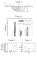
Figure 3 shows a cross section of a typical groove obtained from a "pin on disc" evaluation, perpendicular to the longitudinal direction, -
Figure 4 is a diagram showing the groove depth at room temperature and 650°C for the alloys A, B and C in the "pin on disc" experiment, -
Figure 5 is a diagram showing the volume loss per meter at 650°C for the alloys A, B and C in the "pin on disc" experiment, and -
Figure 6 shows the hardness in HRC for alloy A, B and C. - The industrial production of semi-finished products, components and cutting tools based on powder metallurgical high speed steel started 35 years ago. The first powder metallurgical production of high speed steel was based on hot isostatic pressing (HIP) and consolidation of atomized powders. The HIP step was normally followed by hot forging of the HIP'ed billets. This method of production is still the dominating powder metallurgical method to produce high speed steel.
- The original objective for research and development on powder metallurgical processing of high speed steel was to improve the functional properties and performance of high speed steel in demanding applications. The main advantages from the powder metallurgical manufacturing process are no segregation with a uniform and isotropic microstructure. The well known problems with coarse and severe carbide segregation in conventional cast steel and forged steel are thus avoided in powder metallurgical high speed steel.
- Thus, the powder metallurgical manufacturing method of a high speed steel with sufficient amount of carbon and carbide forming elements, results in a dispersed distribution of carbides that to a large extent solves the problem of low strength and toughness associated with conventionally produced high speed steel.
-
Figure 1 shows acomposite roll 101 for hot-rolling. Theroll 101 comprises anaxially extending core 102 with anenvelope surface 104 and anaxially extending sleeve 103 arranged radially outside saidcore 102. - The
core 102 is manufactured of a material with good mechanical properties and good heat conductive properties, examples of such materials are ductile iron or steel. Thecore 102 is a cylindrical journal that comprises at a first end and at a second end means for support bearings. The support bearings allow the working roll to be mounted in the hot rolling mill. Between said first end and said second end is provided a longitudinal region arranged for shrink fitting of thesleeve 103 onto saidcore 102. - The
sleeve 103 is a cylindrical sleeve with an inner diameter that is dimensioned for shrink fitting thesleeve 103 onto saidcore 102. The wall thickness of thesleeve 103 is dimensioned with respect to heat transfer and work roll lifetime as well as geometrical constraints. In a preferred embodiment of the invention the thickness of the sleeve is 40 millimetres. - According to the invention the
sleeve 103 is made of a high speed steel that with reference to its chemical composition consists of the following elements: 1-3 wt-% Carbon (C), 3-6 wt-% Chromium (Cr), 0-7 wt-% Molybdenum (Mo), 0-15 wt-% Tungsten (W), 3-14 wt-% Vanadium (V), 0-10 wt-% Cobalt (Co), 0-3 wt-% Niobium (Nb), 0-0.5 wt-% Nitrogen (N), 0.2-1 wt-% Yttrium (Y), and remainder iron (Fe) and unavoidable impurities. It should be pointed out that the elements having a lower limit of 0% are optional and can thus be omitted. The manufacturing of thesleeve 103 comprises of a powder of said high speed steel to form a body from said powder. This forming may for example comprise pouring said powder into a capsule in the form of thesleeve 103; the capsule is then evacuated and sealed. In order to consolidate the powder, the capsule is subjected to heat and pressure in a so called hot isostatic processing (HIP) step. - In a preferred embodiment of the invention, the provision of the powder mixture comprises the step of argon gas-atomisation of molten metal comprising said elements into said powder. In a preferred embodiment of the invention, the argon gas-atomisation of the molten high speed steel causes high speed steel particles of a maximum size of 160 µm to be formed.
- After the provision of the powder, the sleeve is formed from said powder. This forming may for example comprise pouring said powder into a capsule; the capsule is then evacuated, e.g. by being subjected to a pressure of below 0.004 mbar for 24 hours in order to evacuate said capsule. The capsule is then sealed in order to maintain said pressure in the capsule. The consolidation of the powder is achieved by subjecting the capsule to an elevated temperature, e.g. about 1150°C, and an elevated pressure, e.g. about 1000 bar, for a long period of time, e.g. two hours. This last consolidation step is called hot isostatic pressing, HIP.
- A soft annealing step follows the HIP step, preferably the soft annealing step is performed at 900°C followed by a temperature decrease to 700°C at a cooling rate of 10°C/hour, from thereon the sleeve is allowed to naturally cool down to room temperature.
- After soft annealing the sleeve may be subjected to machining and preferably a hardening (austenizing) step at 1100°C and three subsequent annealing steps at 560°C for 60 minutes each, with natural cooling to room temperature there between.
- The resulting sleeve from these subsequent steps exhibits a very good uniformity without the aforementioned segregations and coarse carbide structure, and the most important effect is that the yttrium element is evenly distributed in the base-matrix of the high speed steel.
Table 1 Alloy Carbon (C) wt-% Chromium (Cr) wt-% Molybdenum (Mo) wt-% Vanadium (V) wt-% Tungsten (W) wt-% Yttrium (Y) wt-% A 1.28 4.2 5 3.1 6.4 - B 1.18 4.2 5 3.1 6.4 0.5 C 1.19 4.2 5 3.1 6.4 1 - In order to demonstrate the superior properties of the material of the
sleeve 103, a high speed steel was designed without the optional elements, see table 1. The exclusion of the optional elements causes a clear and concise demonstration of the improved high-temperature wear due to the method. A simple evaluation method "pin-on-disc" for high-temperature wear is described below. - Table 1 shows the elements of the high speed steel used in the experiment. Smelts were produced with the elements in table 1, and from these smelts, powders were produced be means of gas atomisation using argon. The powders of alloy B and C in table 1 have a particle size of <160 µm, the powder of alloy A has a particle size of <500 µm.
- In the following description a performed experiment will be described in detail.
- The preparation of samples began with filling of the capsules with powder, with said capsules made from spiral welded tubes with a diameter of 73 mm. The capsules were then exposed to a pressure below 0.004 mbar for 24 hours. The capsules were then sealed in order to maintain said pressure.
- In order to consolidate the powder in the capsules a hot isostatic pressing operation was performed at 1150°C and 1000 bar for 2 hours. The samples were then subjected to a soft annealing step at 900°C followed by a temperature decrease to 700°C at a cooling rate of 10°C/hour, from thereon the samples were allowed to naturally cool down to room temperature.
- The samples were then machined and heat treated with a hardening (austenizing) step at 1100°C and three subsequent annealing steps at 560°C for 60 minutes each, with natural cooling to room temperature there between.
- The final preparation step comprised of stepwise grinding and polishing of the samples in an automatic grinder/polisher. During the final polishing step a 1 µm diamond suspension was used.
-
Figure 2 shows a simplified test set-up used for the tribological testing; this set-up is in the art called "pin on disc". The principle for the "pin on disc" tribological testing is as follows; asample 1 is rotated around anaxis 5 with a speed ω for a number of revolutions. Simultaneously with the rotation of the sample 1 a force F is applied to apin 2 that in turn applies the same force F to a ball 3. The ball 3 is made of Al2O3 and has a diameter of 6 mm. The rotation of thesample 1 and the force F on the ball 3 causes agroove 6 to be formed in thesample 1. - In order to evaluate the wear behaviour at elevated temperatures the lower part of the "pin on disc" set-up is accommodated in a furnace 4. Thus, the furnace 4 can heat the
sample 1, the ball 3 and the lower part of thepin 2 to the desired operating temperature. -
Figure 3 shows a cross section of thegroove 6 perpendicular to the longitudinal direction of thegroove 6. The depth d measured from the polished surface of the sample to the bottom of thegroove 6 is used as a measure of the wear resistance of the sample. Another figure of the wear resistance is thecross-sectional area 7, which is defined as the cross-sectional area of thegroove 6 below the polished surface of thesample 1 perpendicular to the longitudinal direction of thegroove 6. The profile and depth d of thegroove 6 was estimated using a Veeco Wyko NT9100 white light interferometer. - A series of samples according to the description above were produced and tested according to the "pin on disc" procedure outlined above. The "pin on disc" result is presented in
figure 3 . The linear speed in this test was 20 cm/s, the applied force F was 5N and 20N, respectively, and the samples were rotated 20000 revolutions. - As can be seen in
figure 4 the addition of yttrium caused the depth of the groove to decrease at 650°C; see alloy A with a groove depth d equal to 5.7 µm, alloy B with a groove depth d equal to 1,9 µm and alloy C with a groove depth d equal to 3.7 µm. This indicates the anticipated increased wear resistance at elevated temperatures for alloys produced by the inventive method. The addition of 0.5 % yttrium to the high speed steel (Alloy B) caused a reduction of the groove depth d of roughly three times compared to the high speed steel without yttrium (Alloy A). Also the addition of 1% yttrium to the high speed steel (Alloy C) caused a reduction of the groove depth d at 650°C. - A more representative measure of the wear resistance is the volume loss per meter (mm3/m). The calculation of the volume loss per meter is performed by integrating the cross
sectional area 7 over the longitudinal direction of the track and divide by the circumference of the groove. Infigure 5 the volume loss per meter is presented; volume loss for alloy A is 4.6×10⁻⁵ mm3/m, volume loss for alloy B is 1.8×10⁻⁵ mm3/m and finally the volume loss for alloy C is 4×10⁻⁵ mm3/m. The relationship between the yttrium content of the high speed steel and the volume loss per meter thereof is illustrated infigure 5 . Fromfigure 5 one can conclude that the yttrium content of 0.5 % clearly results in the lowest volume loss per meter. A higher yttrium content than 1% also has a beneficial effect on the volume loss per meter. This relationship implies that the yttrium content of 0.5% gives a superior increase in the implied wear resistance of the high speed steel. According to the invention the yttrium content of the high speed steel is within the range 0.2 to 1 weight%. It is preferred that the yttrium content of the high speed steel is more than 0.4 weight%, and less than 0.7 weight% more preferably less than 0.6 weight%, most preferably 0.5 weight%. - In
figure 6 the hardness of the samples is presented. The hardness is 63 HRC for alloy A, the hardness is 57 HRC for alloy B and the hardness is 56 HRC for alloy C. The conclusion fromfigure 6 is that the hardness is reduced with the addition of yttrium. One possible explanation for this reduction is that less carbon is available in the alloys that contain yttrium, thereby reducing the hardness. This illustrates the theory that the wear rate of the high speed steel, infigure 4 , at room temperature is primarily dominated by the hardness of the high speed steel. At room temperature the wear rate increases with decreasing hardness. However, at elevated temperatures, other mechanisms are dominating the wear, such as the growth kinetics and the mechanical properties of the oxide scale.
Claims (18)
- A roll (101) for hot-rolling comprising a body, characterized in that at least a part of an envelope surface (104) of said body is made of a high speed steel that with reference to its chemical composition consists of the following elements, in weight%:1-3 Carbon (C)3-6 Chromium (Cr)0-7 Molybdenum (Mo)0-15 Tungsten (W)3-14 Vanadium (V)0-10 Cobalt (Co)0-3 Niobium (Nb)0-0.5 Nitrogen (N)0.2-1 Yttrium (Y), and
remainder iron (Fe) and unavoidable impurities, wherein Mo+0.5W = 2-10 weight%. - A roll (101) for hot-rolling according to claim 1, wherein said body comprises- an axially extending core (102), and- an axially extending sleeve (103) arranged radially outside said core (102).
- A roll for hot-rolling according to claim 2, wherein said sleeve (103) is made of said high speed steel.
- A roll (101) for hot-rolling according to claim 2 or 3, wherein said sleeve is made of a consolidation of a powder of said high speed steel, which powder is subjected to elevated heat and elevated pressure causing said consolidation.
- A roll (101) for hot-rolling according to any of claims 2-4, wherein said core (102) is made of cast steel or cast iron or forged steel.
- A roll according to any one of claims 2-5, characterised in that the material of said sleeve (103) presents carbide particles that have a mean carbide particle size which is <3µm.
- A roll according to any one of claims 2-6, characterised in that the sleeve (103) has an isotropic microstructure.
- A roll (101) for hot-rolling according to any of claims 2-7, wherein said sleeve (103) is shrink fitted onto said core (102) .
- A roll (101) for hot-rolling according to any preceding claim, wherein the yttrium (Y) content of said high speed steel is more than 0.4 weight%.
- A roll (101) for hot-rolling according to any preceding claim, wherein the yttrium (Y) content of said high speed steel is less than 0.6 weight%.
- A roll (101) for hot-rolling according to any preceding claim, wherein the yttrium (Y) content of said high speed steel is in the range 0.45-0.60 weight%.
- A roll (101) according to any one of the preceding claims, characterised in that Mo+0.5W = 5.0-8.5 weight%.
- A roll (101) according to any one of the preceding claims, characterised in that the carbon (C) content of said high speed steel is in the range of 1.1-1.4 weight%
- A roll according to any one of the preceding claims, characterised in that the chromium (Cr) content of said high speed steel is in the range of 4.0-5.0 weight%.
- A roll according to any one of the preceding claims, characterised in that the Molybdenum (Mo) content of said high speed steel is in the range of 4.5-5.5 weight%.
- A roll according to any one of the preceding claims, characterised in that the tungsten (W) content of said high speed steel is in the range of 6.0-7.0 weight%
- A roll according to any one of the preceding claims, characterised in that the Vanadium (V) content of said high speed steel is in the range of 3.0-5.0 weight%.
- A roll according to any one of the preceding claims, characterised in that the Vanadium (V) content of said high speed steel is in the range of 3.0-3.5 weight%.
Priority Applications (12)
| Application Number | Priority Date | Filing Date | Title |
|---|---|---|---|
| EP11181778A EP2570508A1 (en) | 2011-09-19 | 2011-09-19 | A roll for hot rolling |
| RU2014115715A RU2609115C2 (en) | 2011-09-19 | 2012-09-19 | Roll for hot rolling |
| CN201280045622.5A CN103814147A (en) | 2011-09-19 | 2012-09-19 | Rolls for hot rolling |
| CN201810467190.6A CN108642401A (en) | 2011-09-19 | 2012-09-19 | Roller for hot rolling |
| PCT/EP2012/068429 WO2013041559A1 (en) | 2011-09-19 | 2012-09-19 | A roll for hot rolling |
| EP12759475.2A EP2758559B1 (en) | 2011-09-19 | 2012-09-19 | A roll for hot rolling |
| KR1020147009616A KR101988685B1 (en) | 2011-09-19 | 2012-09-19 | A roll for hot rolling |
| JP2014531205A JP6016927B2 (en) | 2011-09-19 | 2012-09-19 | Hot rolling roll |
| BR112014006532A BR112014006532A2 (en) | 2011-09-19 | 2012-09-19 | hot rolling roll |
| UAA201404172A UA111505C2 (en) | 2011-09-19 | 2012-09-19 | Roll for hot rolling |
| MX2014003248A MX367214B (en) | 2011-09-19 | 2012-09-19 | A roll for hot rolling. |
| US14/345,443 US9993858B2 (en) | 2011-09-19 | 2012-09-19 | Roll for hot rolling |
Applications Claiming Priority (1)
| Application Number | Priority Date | Filing Date | Title |
|---|---|---|---|
| EP11181778A EP2570508A1 (en) | 2011-09-19 | 2011-09-19 | A roll for hot rolling |
Publications (1)
| Publication Number | Publication Date |
|---|---|
| EP2570508A1 true EP2570508A1 (en) | 2013-03-20 |
Family
ID=46852028
Family Applications (2)
| Application Number | Title | Priority Date | Filing Date |
|---|---|---|---|
| EP11181778A Withdrawn EP2570508A1 (en) | 2011-09-19 | 2011-09-19 | A roll for hot rolling |
| EP12759475.2A Not-in-force EP2758559B1 (en) | 2011-09-19 | 2012-09-19 | A roll for hot rolling |
Family Applications After (1)
| Application Number | Title | Priority Date | Filing Date |
|---|---|---|---|
| EP12759475.2A Not-in-force EP2758559B1 (en) | 2011-09-19 | 2012-09-19 | A roll for hot rolling |
Country Status (10)
| Country | Link |
|---|---|
| US (1) | US9993858B2 (en) |
| EP (2) | EP2570508A1 (en) |
| JP (1) | JP6016927B2 (en) |
| KR (1) | KR101988685B1 (en) |
| CN (2) | CN103814147A (en) |
| BR (1) | BR112014006532A2 (en) |
| MX (1) | MX367214B (en) |
| RU (1) | RU2609115C2 (en) |
| UA (1) | UA111505C2 (en) |
| WO (1) | WO2013041559A1 (en) |
Cited By (2)
| Publication number | Priority date | Publication date | Assignee | Title |
|---|---|---|---|---|
| CN109825773A (en) * | 2019-04-10 | 2019-05-31 | 安徽环渤湾高速钢轧辊有限公司 | Thick-walled high-speed steel wear-resistant roll ring and preparation method thereof |
| CN111647812A (en) * | 2020-05-31 | 2020-09-11 | 河冶科技股份有限公司 | Special steel for rolling billet and preparation method thereof |
Families Citing this family (5)
| Publication number | Priority date | Publication date | Assignee | Title |
|---|---|---|---|---|
| DE102014000165B4 (en) * | 2014-01-07 | 2016-06-09 | Horst Diesing | Alloy for matrix intrinsic tribocharged manganese oxide coatings for extended service life of hot working tools made from S (HSS) iron based alloys |
| CN109702016A (en) * | 2018-12-28 | 2019-05-03 | 常州市瑞宏轧辊有限公司 | A kind of novel high rigidity half steel abnormal shape polishing roll and its processing technology |
| CN112941402A (en) * | 2021-01-28 | 2021-06-11 | 黄石中睿科技有限责任公司 | Wear-resistant alloy bar and preparation method thereof |
| CN114713796B (en) * | 2022-05-06 | 2024-04-19 | 湖南三泰新材料股份有限公司 | Hot rolled powder high speed steel and preparation method thereof |
| KR20240154925A (en) * | 2023-04-19 | 2024-10-28 | 주식회사 포스코 | MANUFACTURING METHOD FOR MOLTEN STEEL HAVING HIGH Cr AND SLAB, MANUFACTURING METHOD FOR ROLLING ROLL |
Citations (4)
| Publication number | Priority date | Publication date | Assignee | Title |
|---|---|---|---|---|
| US4941251A (en) | 1983-04-22 | 1990-07-17 | Hitachi, Ltd. | Rollers for rolling mills |
| JPH02194144A (en) * | 1989-01-24 | 1990-07-31 | Daido Steel Co Ltd | High-speed tool steel |
| US6095957A (en) | 1996-06-18 | 2000-08-01 | Kawasaki Steel Corporation | Roll for hot rolling having enhanced abrasion resistance and reduced carbide segregation |
| JP2003129101A (en) * | 2001-10-24 | 2003-05-08 | Sanyo Special Steel Co Ltd | Press sintering powder |
Family Cites Families (17)
| Publication number | Priority date | Publication date | Assignee | Title |
|---|---|---|---|---|
| US4469514A (en) * | 1965-02-26 | 1984-09-04 | Crucible, Inc. | Sintered high speed tool steel alloy composition |
| JPS5785952A (en) * | 1980-11-17 | 1982-05-28 | Daido Steel Co Ltd | High-speed steel |
| JPH0717986B2 (en) * | 1985-03-16 | 1995-03-01 | 大同特殊鋼株式会社 | Alloy tool steel |
| JPH0791620B2 (en) * | 1985-03-16 | 1995-10-04 | 大同特殊鋼株式会社 | High speed tool steel with excellent grindability |
| JPS6393604A (en) * | 1986-10-06 | 1988-04-23 | Bridgestone Corp | Pneumatic tire |
| JP2555139B2 (en) | 1988-03-18 | 1996-11-20 | 株式会社クボタ | Composite ring roll |
| UA34624C2 (en) * | 1998-08-21 | 2001-06-15 | Закрите Акціонерне Товариство "Елмет-Рол - Група Медовара" | Composite roll for hot mills |
| JP2999472B1 (en) | 1999-03-10 | 2000-01-17 | 虹技株式会社 | Roll material |
| RU2164961C2 (en) | 1999-03-17 | 2001-04-10 | Государственный космический научно-производственный центр им. М.В. Хруничева | High-speed steel |
| JP3574776B2 (en) * | 1999-05-06 | 2004-10-06 | 日本高周波鋼業株式会社 | High wear resistance, high toughness, high speed tool steel |
| JP3448021B2 (en) | 2000-09-28 | 2003-09-16 | 虹技株式会社 | Multi-layer roll for hot rolling |
| AT410448B (en) | 2001-04-11 | 2003-04-25 | Boehler Edelstahl | COLD WORK STEEL ALLOY FOR THE POWDER METALLURGICAL PRODUCTION OF PARTS |
| CN100413992C (en) * | 2006-01-25 | 2008-08-27 | 周向儒 | A kind of high-speed steel and its heat treatment process |
| CN100465324C (en) * | 2007-06-26 | 2009-03-04 | 郑州航空工业管理学院 | A kind of low-alloy high-speed steel roll material and its manufacturing method |
| JP5311941B2 (en) * | 2007-11-13 | 2013-10-09 | セイコーエプソン株式会社 | Metal powder for powder metallurgy, sintered body and method for producing sintered body |
| CN101797630B (en) * | 2010-04-16 | 2011-09-21 | 北京工业大学 | Modified high-speed steel roller and preparation method thereof |
| CN101838774A (en) * | 2010-05-10 | 2010-09-22 | 金文平 | High speed steel and productive technology thereof |
-
2011
- 2011-09-19 EP EP11181778A patent/EP2570508A1/en not_active Withdrawn
-
2012
- 2012-09-19 BR BR112014006532A patent/BR112014006532A2/en not_active IP Right Cessation
- 2012-09-19 US US14/345,443 patent/US9993858B2/en not_active Expired - Fee Related
- 2012-09-19 RU RU2014115715A patent/RU2609115C2/en not_active IP Right Cessation
- 2012-09-19 UA UAA201404172A patent/UA111505C2/en unknown
- 2012-09-19 CN CN201280045622.5A patent/CN103814147A/en active Pending
- 2012-09-19 MX MX2014003248A patent/MX367214B/en active IP Right Grant
- 2012-09-19 KR KR1020147009616A patent/KR101988685B1/en not_active Expired - Fee Related
- 2012-09-19 EP EP12759475.2A patent/EP2758559B1/en not_active Not-in-force
- 2012-09-19 JP JP2014531205A patent/JP6016927B2/en not_active Expired - Fee Related
- 2012-09-19 CN CN201810467190.6A patent/CN108642401A/en active Pending
- 2012-09-19 WO PCT/EP2012/068429 patent/WO2013041559A1/en not_active Ceased
Patent Citations (4)
| Publication number | Priority date | Publication date | Assignee | Title |
|---|---|---|---|---|
| US4941251A (en) | 1983-04-22 | 1990-07-17 | Hitachi, Ltd. | Rollers for rolling mills |
| JPH02194144A (en) * | 1989-01-24 | 1990-07-31 | Daido Steel Co Ltd | High-speed tool steel |
| US6095957A (en) | 1996-06-18 | 2000-08-01 | Kawasaki Steel Corporation | Roll for hot rolling having enhanced abrasion resistance and reduced carbide segregation |
| JP2003129101A (en) * | 2001-10-24 | 2003-05-08 | Sanyo Special Steel Co Ltd | Press sintering powder |
Cited By (2)
| Publication number | Priority date | Publication date | Assignee | Title |
|---|---|---|---|---|
| CN109825773A (en) * | 2019-04-10 | 2019-05-31 | 安徽环渤湾高速钢轧辊有限公司 | Thick-walled high-speed steel wear-resistant roll ring and preparation method thereof |
| CN111647812A (en) * | 2020-05-31 | 2020-09-11 | 河冶科技股份有限公司 | Special steel for rolling billet and preparation method thereof |
Also Published As
| Publication number | Publication date |
|---|---|
| BR112014006532A2 (en) | 2017-04-04 |
| JP6016927B2 (en) | 2016-10-26 |
| MX367214B (en) | 2019-08-09 |
| JP2014531982A (en) | 2014-12-04 |
| KR101988685B1 (en) | 2019-06-12 |
| KR20140064953A (en) | 2014-05-28 |
| RU2014115715A (en) | 2015-10-27 |
| US9993858B2 (en) | 2018-06-12 |
| EP2758559A1 (en) | 2014-07-30 |
| US20150018185A1 (en) | 2015-01-15 |
| MX2014003248A (en) | 2014-04-10 |
| EP2758559B1 (en) | 2019-08-28 |
| WO2013041559A1 (en) | 2013-03-28 |
| CN103814147A (en) | 2014-05-21 |
| UA111505C2 (en) | 2016-05-10 |
| CN108642401A (en) | 2018-10-12 |
| RU2609115C2 (en) | 2017-01-30 |
Similar Documents
| Publication | Publication Date | Title |
|---|---|---|
| EP2758559B1 (en) | A roll for hot rolling | |
| EP2570507A1 (en) | A method for producing high speed steel | |
| US4249945A (en) | Powder-metallurgy steel article with high vanadium-carbide content | |
| AU2020208099B2 (en) | 3D printed high carbon content steel and method of preparing the same | |
| JP7131572B2 (en) | Cemented Carbide and Cemented Carbide Composite Rolls for Rolling | |
| JP5121276B2 (en) | High-speed steel alloy composite products | |
| JPH07166300A (en) | High speed steel powder alloy | |
| JP2791445B2 (en) | High speed steel based sintered alloy | |
| US11045849B2 (en) | Composite cemented carbide roll | |
| JP3032995B2 (en) | High-speed steel-based sintered alloy for steel roll, roll body and manufacturing method | |
| JP3032997B2 (en) | High speed steel based sintered alloy | |
| JP3032996B2 (en) | High-speed steel-based sintered alloy for steel roll, roll body and manufacturing method | |
| JPH11246949A (en) | High speed steel series sintered alloy excellent in cracking resistance and roll for rolling using it | |
| JP2964197B2 (en) | High-speed steel-based sintered alloy for steel roll, roll body and manufacturing method | |
| JP2972031B2 (en) | High-speed steel-based sintered alloy for steel roll, roll body and manufacturing method | |
| JPH11246950A (en) | Hot-strip mill roll | |
| JP2963579B2 (en) | High speed steel based sintered alloy | |
| JPH062080A (en) | High speed steel series sintered alloy | |
| JPH062082A (en) | High speed steel type sintered alloy |
Legal Events
| Date | Code | Title | Description |
|---|---|---|---|
| PUAI | Public reference made under article 153(3) epc to a published international application that has entered the european phase |
Free format text: ORIGINAL CODE: 0009012 |
|
| AK | Designated contracting states |
Kind code of ref document: A1 Designated state(s): AL AT BE BG CH CY CZ DE DK EE ES FI FR GB GR HR HU IE IS IT LI LT LU LV MC MK MT NL NO PL PT RO RS SE SI SK SM TR |
|
| AX | Request for extension of the european patent |
Extension state: BA ME |
|
| STAA | Information on the status of an ep patent application or granted ep patent |
Free format text: STATUS: THE APPLICATION HAS BEEN WITHDRAWN |
|
| 18W | Application withdrawn |
Effective date: 20130906 |